US9856162B2 - Glass melting tank having a doghouse, and method for heating the charge material in such glass melting tanks - Google Patents
Glass melting tank having a doghouse, and method for heating the charge material in such glass melting tanks Download PDFInfo
- Publication number
- US9856162B2 US9856162B2 US13/695,650 US201113695650A US9856162B2 US 9856162 B2 US9856162 B2 US 9856162B2 US 201113695650 A US201113695650 A US 201113695650A US 9856162 B2 US9856162 B2 US 9856162B2
- Authority
- US
- United States
- Prior art keywords
- doghouse
- melting tank
- charge material
- glass
- recited
- Prior art date
- Legal status (The legal status is an assumption and is not a legal conclusion. Google has not performed a legal analysis and makes no representation as to the accuracy of the status listed.)
- Active, expires
Links
- 238000002844 melting Methods 0.000 title claims abstract description 88
- 230000008018 melting Effects 0.000 title claims abstract description 87
- 239000000463 material Substances 0.000 title claims abstract description 65
- 239000011521 glass Substances 0.000 title claims abstract description 33
- 238000010438 heat treatment Methods 0.000 title claims abstract description 9
- 238000000034 method Methods 0.000 title claims description 10
- 239000000156 glass melt Substances 0.000 claims description 27
- 239000000155 melt Substances 0.000 claims description 17
- 230000005855 radiation Effects 0.000 claims description 8
- 238000005245 sintering Methods 0.000 claims description 7
- 230000035515 penetration Effects 0.000 claims description 6
- 230000000694 effects Effects 0.000 claims description 4
- 239000000428 dust Substances 0.000 abstract description 12
- 239000007789 gas Substances 0.000 description 20
- 238000010276 construction Methods 0.000 description 4
- 238000011109 contamination Methods 0.000 description 3
- 238000011161 development Methods 0.000 description 3
- 230000018109 developmental process Effects 0.000 description 3
- 239000002994 raw material Substances 0.000 description 3
- 239000011819 refractory material Substances 0.000 description 3
- 230000009471 action Effects 0.000 description 2
- 230000008901 benefit Effects 0.000 description 2
- 238000002485 combustion reaction Methods 0.000 description 2
- 238000001816 cooling Methods 0.000 description 2
- 238000005260 corrosion Methods 0.000 description 2
- 230000007797 corrosion Effects 0.000 description 2
- 238000009826 distribution Methods 0.000 description 2
- 238000009434 installation Methods 0.000 description 2
- 239000000203 mixture Substances 0.000 description 2
- 238000012986 modification Methods 0.000 description 2
- 230000004048 modification Effects 0.000 description 2
- 230000001172 regenerating effect Effects 0.000 description 2
- 230000007704 transition Effects 0.000 description 2
- 241000863032 Trieres Species 0.000 description 1
- 230000004075 alteration Effects 0.000 description 1
- 230000005540 biological transmission Effects 0.000 description 1
- 230000008859 change Effects 0.000 description 1
- 230000002301 combined effect Effects 0.000 description 1
- 150000001875 compounds Chemical class 0.000 description 1
- 238000000151 deposition Methods 0.000 description 1
- 238000005516 engineering process Methods 0.000 description 1
- 238000007710 freezing Methods 0.000 description 1
- 230000008014 freezing Effects 0.000 description 1
- 238000004519 manufacturing process Methods 0.000 description 1
- 238000010309 melting process Methods 0.000 description 1
- 230000010355 oscillation Effects 0.000 description 1
- 239000002245 particle Substances 0.000 description 1
- 230000000149 penetrating effect Effects 0.000 description 1
- 230000000737 periodic effect Effects 0.000 description 1
- 230000008569 process Effects 0.000 description 1
- 230000000717 retained effect Effects 0.000 description 1
Images



Classifications
-
- C—CHEMISTRY; METALLURGY
- C03—GLASS; MINERAL OR SLAG WOOL
- C03B—MANUFACTURE, SHAPING, OR SUPPLEMENTARY PROCESSES
- C03B3/00—Charging the melting furnaces
- C03B3/02—Charging the melting furnaces combined with preheating, premelting or pretreating the glass-making ingredients, pellets or cullet
- C03B3/023—Preheating
-
- C—CHEMISTRY; METALLURGY
- C03—GLASS; MINERAL OR SLAG WOOL
- C03B—MANUFACTURE, SHAPING, OR SUPPLEMENTARY PROCESSES
- C03B3/00—Charging the melting furnaces
-
- C—CHEMISTRY; METALLURGY
- C03—GLASS; MINERAL OR SLAG WOOL
- C03B—MANUFACTURE, SHAPING, OR SUPPLEMENTARY PROCESSES
- C03B3/00—Charging the melting furnaces
- C03B3/005—Charging the melting furnaces using screw feeders
-
- C—CHEMISTRY; METALLURGY
- C03—GLASS; MINERAL OR SLAG WOOL
- C03B—MANUFACTURE, SHAPING, OR SUPPLEMENTARY PROCESSES
- C03B3/00—Charging the melting furnaces
- C03B3/02—Charging the melting furnaces combined with preheating, premelting or pretreating the glass-making ingredients, pellets or cullet
-
- C—CHEMISTRY; METALLURGY
- C03—GLASS; MINERAL OR SLAG WOOL
- C03B—MANUFACTURE, SHAPING, OR SUPPLEMENTARY PROCESSES
- C03B5/00—Melting in furnaces; Furnaces so far as specially adapted for glass manufacture
- C03B5/04—Melting in furnaces; Furnaces so far as specially adapted for glass manufacture in tank furnaces
-
- Y—GENERAL TAGGING OF NEW TECHNOLOGICAL DEVELOPMENTS; GENERAL TAGGING OF CROSS-SECTIONAL TECHNOLOGIES SPANNING OVER SEVERAL SECTIONS OF THE IPC; TECHNICAL SUBJECTS COVERED BY FORMER USPC CROSS-REFERENCE ART COLLECTIONS [XRACs] AND DIGESTS
- Y02—TECHNOLOGIES OR APPLICATIONS FOR MITIGATION OR ADAPTATION AGAINST CLIMATE CHANGE
- Y02P—CLIMATE CHANGE MITIGATION TECHNOLOGIES IN THE PRODUCTION OR PROCESSING OF GOODS
- Y02P40/00—Technologies relating to the processing of minerals
- Y02P40/50—Glass production, e.g. reusing waste heat during processing or shaping
Definitions
- the present invention relates to a glass melting tank having at least one doghouse for the introduction of the charge material, and having at least one charging device.
- the introduced raw material mixture has a too-short dwell time in the pre-sintered zone, i.e. the doghouse. It is known that for a mixture of raw materials suitable for production of a glass melt a finite period of time is required in order to sinter the surface as a pile in an environment having a temperature of greater than 1000° C. This surface sintering of the supplied batch prevents the danger of the above-described dust contamination.
- the dwell time of the material in the doghouse can be determined from the raw material bulk, the surface of the doghouse, the density of the pile, and the charging quantity per time unit.
- the mass flow per hour conveyed through the doghouse into the melt installation is decisive.
- the use of the K factor in connection with the doghouse is not known.
- the object of the present invention is to improve charging technology in glass melting tanks of the type named above such that heat losses to the atmosphere are reduced, and transport of dust into the upper furnace of the melting tank is reduced, while the heating of the charge material is nonetheless intensified.
- this object is achieved in that the transport path of the charge material in the doghouse is so long that the charge material is heated in the doghouse up to an at least partial melting,
- the doghouse has an inner length (LV) in the direction toward the melting tank of at least 2250 mm,
- the doghouse contains an insulating roof having a length (LG) of at least 1200 mm,
- the roof has an end wall facing the charging device that encloses, with the roof, a gas chamber that is open toward the melting tank, and
- the enlargement of the doghouse connected with the change according to the present invention of the upper construction of the doghouse achieves the result that a sufficient radiant heat is present in the doghouse, which ensures that the batch is both pre-heated and pre-sintered, and that there is no danger of a “freezing of the melt” in the front part area.
- the flow of the glass into the doghouse region is determined by the thermal convection.
- this means that given an inner length (LV) of the doghouse up to the inner edge of the upper furnace of the melting tank of approximately 2250 mm, and a length (LG) of the gas chamber over the melt of the doghouse of approximately 1200 mm, and given a ratio of the charge quantity (throughput) to the surface of the doghouse [P/F K] of less than 3.5 t/h ⁇ m 2 , a dwell time of approximately 2.5 minutes is present, which is sufficient for a pre-sintering at the surface of the batch piles.
- a further advantage of the measures according to the present invention is that in the actual region of the melting tank the melting is temporally and spatially shortened, increasing the efficiency of the installation.
- the end wall has a lower edge that is situated above a plane (E-E) in which the upper tank edge is situated, and that limits a charging gap.
- the charging device contains an insert plate that can be moved periodically, by which the portions of charge material can be fed through the charging gap into the doghouse and onto the melt.
- the charging device has a screw conveyor by which the charge material can be fed into the doghouse and onto the melt, the screw conveyor having according to the present invention a housing that is set into the end wall of the doghouse in a sealed fashion.
- the roof of the doghouse is realized so as to be curved upward in the longitudinal direction of the doghouse, the roof of the doghouse usefully being realized so as to be inclined upward in the direction toward the melting tank.
- the gas chamber has a height (H) over the plane (E-E) of the tank edge of at least 600 mm.
- the doghouse has side walls that enclose between them an angle (a) of 0 to 45°, opening in the direction toward the melting tank, preferably an angle of 5 to 30°.
- the doghouse has at its inlet into the melt tank a width (BV) of at least 1000 mm. This ensures a secure transition of the charge material into the melting tank.
- the present invention also relates to a method for heating charge material in glass melting tanks having at least one doghouse having a charging device for introducing the charge material.
- such a method is characterized according to the present invention in that the charge material is heated and sintered in the doghouse from above by the penetration of thermal radiation from the tank space into the doghouse,
- the charge material is heated and sintered in the doghouse from below by a flow and by the penetration of the glass melt up to an at least partial melting
- the transport path of the charge material in the doghouse is chosen to be between 2.25 and 5 m, and/or if the width (BV) of the transport path of the charge material in the doghouse at the inlet into the melting tank is chosen to be at least 1.0 m.
- a particularly good heat exchange between the gas chamber in the doghouse and the gas chamber over the glass melt is achieved if the position of the melt surface in the gas chamber in the insert chamber is selected such that there remains a minimum distance of 600 mm relative to the highest point of the roof.
- FIGS. 4 and 7 show a comparison with the prior art.
- FIG. 1 shows a vertical cross-section through a glass melting tank according to the present invention in connection with vertical longitudinal sections through two doghouses
- FIG. 2 shows an enlarged detail from FIG. 1 , with dimensional indications
- FIG. 3 shows an enlarged detail from a horizontal section through a tank corner and the adjacent doghouse
- FIG. 4 shows a representation corresponding to FIG. 1 of a glass melting tank according to the prior art, having a standard doghouse
- FIG. 5 shows the left half of FIG. 1 in an enlarged scale and having an insert plate as a charging device in operation
- FIG. 6 shows the left half of FIG. 1 in an enlarged scale and having a screw conveyor as a charging device in operation
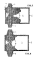
- FIG. 7 shows a top view of a glass melting tank in the operating state, having a carpet of unsintered charge material (prior art), and
- FIG. 8 shows a top view of the contents of a glass melting tank according to the present invention analogous to FIG. 7 , having a carpet of sintered charge material.
- FIG. 9 shows an alternate embodiment of the construction of the doghouse of FIG. 5 .
- FIG. 10 shows a further alternate embodiment of the construction of the doghouse of FIG. 5 .
- FIGS. 1 and 2 show a glass melting tank 1 that together with its contents, a glass melt 2 , is heated by burner batteries 3 that are situated in end wall 1 a of melting tank 1 under the opening of a respective shaft 4 for combustion air.
- These shafts 4 are connected to heat exchangers, for example from the group of regenerators.
- Burner batteries 3 and shafts 4 are operated in alternating fashion in a known manner, e.g. in 15- to 30-minute cycles; i.e., while the one burner battery 3 is operated the exhaust gases are drawn off via the respective other shaft 4 , and vice versa.
- doghouses 6 On both sides of melting tank 1 , there are situated, in mirror-symmetrical arrangement, so-called doghouses 6 , also called front parts, each having a roof 7 that can be curved upward (see FIG. 10 ), and having an end wall 8 , which together enclose a gas chamber 9 .
- These doghouses 6 are connected to a gas chamber 10 over glass melt 2 in melting tank 1 .
- Melting tank 1 and doghouses 6 terminate upward in a common horizontal plane (E-E).
- the roof 7 a of the doghouse 6 may be realized so as to be curved upward in the longitudinal direction of the doghouse (see FIG. 9 ), the roof 7 b of the doghouse 6 usefully being realized so as to be inclined upward in the direction toward the melting tank 1 (see FIG. 10 ).
- End walls 8 terminate downward with a lower edge 11 that leaves open a charging gap 11 a , limited as narrowly as possible, over the plane (E-E) for the dosage of charge material.
- the length (LG) of gas chamber 9 under roof 7 , from the end wall 8 to a side wall 1 c of the melting tank 1 is a minimum of approximately 70% of the inner length (LV) of doghouse 6 , from a lower end wall 8 a to the side wall 1 c , such that between end wall 8 and the adjacent edge of melting tank 1 and doghouse 6 there still remains free a surface for depositing charge material 14 over glass melt 2 .
- the inner length (LV) of the doghouse 6 from the lower end wall 8 a to the inner edge of the side wall 1 c of the melting tank may be approximately 2250 mm.
- height H of gas chamber 9 over plane E-E should be at least 600 mm in order to promote the input of energy through radiation and/or flame gases. However, values up to 900 mm and greater are also conceivable. Given a curve of roof 7 that falls off outwardly, dimension H holds for the height at the entry of doghouse 6 into gas chamber 10 of melting tank 1 .
- doghouse 6 has two side walls 6 a and 6 b that are connected to melting tank 1 and that enclose between them an angle ⁇ that opens in the direction toward melting tank 1 and can be between 0 and 45°, preferably between 5 and 30°.
- This, and width BV of at least 1000 mm, preferably at least 1500 mm, at the transition point make it possible for the flow paths of the glass melt also to run inside doghouses 6 and to take part in the heat exchange to a very significant extent.
- FIG. 4 shows the prior art in a corresponding representation; for better understanding, reference characters previously used have been uniformly retained for corresponding parts.
- a side wall 1 c of melting tank 1 over the very short doghouse 6 there is situated an opening before which is positioned a slide valve 1 d .
- the space limited thereby is so small that neither the flame gases nor the radiation thereof have any significant influence on the thermal input into charge material 14 from above.
- the thermal input through glass melt 2 from below (thick arrows) is also very limited, so that charge material 14 moves into melting tank 1 in an unsintered state. The action is explained in more detail in connection with FIG. 7 .
- FIG. 5 shows a corresponding specific embodiment according to the present invention.
- doghouse 6 and roof 7 have allocated to them a charging device 12 that contains a supply container 13 having a regulable floor outlet 13 a for charge material 14 .
- an obliquely positioned insert plate 15 which is set into periodic oscillations at a low frequency by a drive 16 (not shown in detail).
- charge material 14 is supplied in portions onto the surface of glass melt 2 , in the direction toward charging gap 11 a , and travels in the form of “pillows” 17 through gas chamber 9 in the direction toward melting tank 1 , where it is diverted to a melt outlet.
- FIG. 6 shows an alternative specific embodiment.
- the inner length of roof 7 here corresponds to inner length LV of doghouse 6 in FIGS. 2 and 3 .
- a charging device 20 that contains a supply container 13 having a regulable floor outlet for charge material 14 .
- a horizontal screw conveyor 21 that is driven by a motor M.
- Screw conveyor 21 has a cylindrical housing 21 a that is guided through end wall 8 in sealed fashion. In this way, charge material 14 is supplied onto the surface of glass melt 2 inside doghouse 6 , and moves, in the form of “pillows” 17 , through gas chamber 9 in the direction toward melting tank 1 , where it is diverted to a melt outlet (not shown).
- the spatial form of the volume and the temperature control inside doghouses 6 are selected such that within glass melt 2 there arises a flow characteristic in accordance with the depicted arrows. Due to thermokinetic effects, underneath charge material 14 there arises a flow in the direction toward the inner end of doghouses 6 , causing glass melt 2 to emit a part of its thermal capacity to charge material 14 . Due to the cooling, glass melt 2 sinks in the direction of the floor of doghouse 6 and melting tank 1 , and returns back into this tank. From above, charge material 14 is heated by the thermal radiation penetrating into gas chamber 9 . Due to this combined effect, charge material 14 is heated to a high temperature that promotes a partial melting of the particles, a process that can also be referred to as sintering, and that largely prevents the development of dust.
- FIG. 7 shows the distribution of unsintered charge material 14 as occurs in the prior art.
- a relatively large portion of the melt surface is covered, so that the thermal input into melt 2 is relatively low.
- FIG. 8 shows the distribution of sintered charge material 14 as is the case for the subject matter of the present invention. A significantly larger portion of the melt surface is left open, so that the heat input into melt 2 is correspondingly greater.
- a combination effect takes place in the glass melting tank according to the present invention.
- the spatial form of the volume and the temperature control inside melting tank 1 are selected such that inside glass melt 2 a flow pattern arises in accordance with the arrows in FIGS. 4 through 6 .
- Due to the thermokinetic effect underneath charge material 14 there arises a flow in the direction toward end wall 1 a and burner batteries 3 and into doghouses 6 , causing the glass melt here as well to emit a part of its thermal capacity upward to charge material 14 .
- FIG. 8 illustrates that charge material 14 , starting from the respective doghouse 6 , through the surface flow as shown in FIGS. 5 and 6 , is hardened by sintering to form a kind of “carpet” that leaves open a very large portion of the melt surface, which promotes thermal input by radiation. In particular, in this way the carrying of charge material into the melt output is also prevented.
- characteristic value K plays a decisive role.
- K is the ratio between the throughput (P) of the charge material through the doghouse (in tonnes/hour) and the inner surface (F) of the doghouse (in m 2 ), such that given a transport path through the doghouse according to dimensions LV and LG of the doghouse, characteristic value K is not to exceed a value of 3.5 t/h ⁇ m 2 .
- the doghouse is to be fashioned in such a way that the thermal and mechanical preconditions are created for the introduction of sufficient quantities of charge material in a partly sintered state via the doghouse into a melting tank, while maintaining the floatability of the sintered products.
- the K value is not to exceed a value of 3.5 t/h ⁇ m 2 .
Landscapes
- Chemical & Material Sciences (AREA)
- Engineering & Computer Science (AREA)
- Materials Engineering (AREA)
- Organic Chemistry (AREA)
- Glass Melting And Manufacturing (AREA)
- Furnace Charging Or Discharging (AREA)
- Re-Forming, After-Treatment, Cutting And Transporting Of Glass Products (AREA)
- Tunnel Furnaces (AREA)
- Vertical, Hearth, Or Arc Furnaces (AREA)
Applications Claiming Priority (4)
| Application Number | Priority Date | Filing Date | Title |
|---|---|---|---|
| DE102010020176.6 | 2010-05-11 | ||
| DE102010020176 | 2010-05-11 | ||
| DE102010020176A DE102010020176A1 (de) | 2010-05-11 | 2010-05-11 | Glas-Schmelzwanne mit U-Flammenbeheizung und Verfahren zum Betrieb |
| PCT/EP2011/002217 WO2011141136A1 (de) | 2010-05-11 | 2011-05-04 | Glas-schmelzwanne mit vorbau und verfahren zum betrieb |
Publications (2)
| Publication Number | Publication Date |
|---|---|
| US20130114638A1 US20130114638A1 (en) | 2013-05-09 |
| US9856162B2 true US9856162B2 (en) | 2018-01-02 |
Family
ID=44118749
Family Applications (1)
| Application Number | Title | Priority Date | Filing Date |
|---|---|---|---|
| US13/695,650 Active 2034-08-07 US9856162B2 (en) | 2010-05-11 | 2011-05-04 | Glass melting tank having a doghouse, and method for heating the charge material in such glass melting tanks |
Country Status (8)
| Country | Link |
|---|---|
| US (1) | US9856162B2 (pl) |
| EP (1) | EP2569257B1 (pl) |
| JP (1) | JP5717844B2 (pl) |
| CN (1) | CN102884012B (pl) |
| DE (2) | DE102010020176A1 (pl) |
| PL (1) | PL2569257T3 (pl) |
| RU (1) | RU2520208C1 (pl) |
| WO (1) | WO2011141136A1 (pl) |
Cited By (4)
| Publication number | Priority date | Publication date | Assignee | Title |
|---|---|---|---|---|
| US20190263701A1 (en) * | 2012-07-03 | 2019-08-29 | Johns Manville | Processes for producing molten glasses from glass batches using turbulent submerged combustion melting, and systems for carrying out such processes |
| US11912608B2 (en) | 2019-10-01 | 2024-02-27 | Owens-Brockway Glass Container Inc. | Glass manufacturing |
| US12252434B2 (en) | 2020-09-30 | 2025-03-18 | Owens-Brockway Glass Container Inc. | Feeder alcove and batch feeding apparats for a melter |
| US12371361B2 (en) | 2020-09-30 | 2025-07-29 | Owens-Brockway Glass Container Inc. | Submerged feedstock charging of melting vessels |
Families Citing this family (9)
| Publication number | Priority date | Publication date | Assignee | Title |
|---|---|---|---|---|
| FR2991759B1 (fr) * | 2012-06-12 | 2014-06-20 | Saint Gobain Isover | Installation de fusion de verre |
| CN104724907B (zh) * | 2013-12-24 | 2018-05-25 | 肖自江 | 节能环保玻璃棉生产方法及玻璃棉熔窑 |
| CN104724905B (zh) * | 2013-12-24 | 2018-05-04 | 肖自江 | 节能环保玻璃酒瓶生产方法及玻璃酒瓶熔窑 |
| DE102015108195B4 (de) | 2015-04-27 | 2017-05-11 | Beteiligungen Sorg Gmbh & Co. Kg | Glasschmelzanlage mit einer Schmelzwanne mit U-Flammenbeheizung |
| EP3088369B1 (de) * | 2015-04-27 | 2019-02-13 | Beteiligungen Sorg GmbH & Co. KG | Glasschmelzanlage |
| KR102500724B1 (ko) * | 2016-08-26 | 2023-02-16 | 코닝 인코포레이티드 | 유리 물품 제조를 위한 장치 및 방법 |
| KR102523494B1 (ko) * | 2017-06-28 | 2023-04-20 | 코닝 인코포레이티드 | 유리 형성 장치들을 위한 멜터들 |
| CN111458544B (zh) * | 2020-04-18 | 2020-12-11 | 无锡市恒通电器有限公司 | 一种智能电表及其生产用便捷式防止堵塞的注塑装置 |
| WO2024226239A1 (en) * | 2023-04-24 | 2024-10-31 | Corning Incorporated | Melters for glass forming apparatuses |
Citations (18)
| Publication number | Priority date | Publication date | Assignee | Title |
|---|---|---|---|---|
| GB406577A (en) | 1933-08-01 | 1934-03-01 | United Glass Bottle Mfg Ltd | Improvements in or relating to methods of and means for feeding raw material to glass melting furnaces |
| US2397852A (en) * | 1944-12-23 | 1946-04-02 | Saint Gobain | Glassmaking furnace |
| US2890547A (en) | 1951-11-10 | 1959-06-16 | Emhart Mfg Co | Apparatus for and method of making glass |
| US3074568A (en) * | 1958-02-05 | 1963-01-22 | Libbey Owens Ford Glass Co | Method of and apparatus for feeding glass batch materials |
| US3219209A (en) * | 1962-06-18 | 1965-11-23 | Libbey Owens Ford Glass Co | Apparatus for delivering fusible material to a glass melting furnace |
| US3294506A (en) * | 1962-06-19 | 1966-12-27 | Libbey Owens Ford Glass Co | Method and apparatus for consolidating batch |
| GB1067240A (en) | 1964-12-21 | 1967-05-03 | Libbey Owens Ford Glass Co | Method and apparatus for feeding glass making materials to a glass melting tank furnace |
| US3436200A (en) * | 1965-04-22 | 1969-04-01 | Libbey Owens Ford Co | Method of feeding glass batch material |
| US3836349A (en) * | 1972-10-26 | 1974-09-17 | Ppg Industries Inc | Method of making glass |
| GB1425461A (en) | 1972-02-09 | 1976-02-18 | Glass Works Equipment Ltd | Charging of glass furnaces |
| US3941576A (en) * | 1974-11-29 | 1976-03-02 | Ppg Industries, Inc. | Method and apparatus for making molten glass with batch guiding means |
| FR2299277A1 (fr) | 1975-01-31 | 1976-08-27 | Pilkington Brothers Ltd | Proce |
| US4329165A (en) * | 1981-02-26 | 1982-05-11 | Ppg Industries, Inc. | Method for enhanced melting of glass batch and apparatus therefor |
| DE8304858U1 (de) | 1983-07-14 | Nikolaus Sorg GmbH & Co KG, 8770 Lohr a. Main | Einlegevorrichtung für einen Glasschmelzofen | |
| US5123942A (en) * | 1991-03-21 | 1992-06-23 | Frazier-Simplex, Inc. | System for charging batch/cullet in a glass furnace |
| EP0580048A1 (de) | 1992-07-22 | 1994-01-26 | BETEILIGUNGEN SORG GMBH & CO. KG | Vorrichtung zum Einlegen von Chargiermaterial in Glasschmelzöfen |
| US5906119A (en) | 1994-11-08 | 1999-05-25 | Saint-Gobain Vitrage | Process and device for melting glass |
| DE202009014937U1 (de) | 2009-05-26 | 2010-09-02 | Eme Maschinenfabrik Clasen Gmbh | Vorrichtung zum Beschicken von Glas-Schmelzöfen mit schüttfähigen Glasgemengen |
Family Cites Families (5)
| Publication number | Priority date | Publication date | Assignee | Title |
|---|---|---|---|---|
| JPS52111912A (en) * | 1976-03-18 | 1977-09-20 | Asahi Glass Co Ltd | Glass material melting control method |
| SU1362711A1 (ru) * | 1986-03-07 | 1987-12-30 | Производственное Объединение "Смоленскстеклотара" | Пр моточна регенеративна стекловаренна печь |
| SU1604757A1 (ru) * | 1988-12-26 | 1990-11-07 | Курловский Стекольный Завод Им.Володарского | Стекловаренна ванна печь |
| RU2250879C2 (ru) * | 2003-06-05 | 2005-04-27 | Кондрашов Дмитрий Валерьевич | Способ варки бесцветных и цветных железосодержащих стекол из стеклянного боя |
| RU2291116C1 (ru) * | 2005-09-14 | 2007-01-10 | Сергей Владимирович Перфилов | Стекловаренная печь |
-
2010
- 2010-05-11 DE DE102010020176A patent/DE102010020176A1/de not_active Withdrawn
- 2010-05-11 DE DE202010017541U patent/DE202010017541U1/de not_active Expired - Lifetime
-
2011
- 2011-05-04 WO PCT/EP2011/002217 patent/WO2011141136A1/de not_active Ceased
- 2011-05-04 RU RU2012153197/03A patent/RU2520208C1/ru active
- 2011-05-04 US US13/695,650 patent/US9856162B2/en active Active
- 2011-05-04 CN CN201180022944.3A patent/CN102884012B/zh active Active
- 2011-05-04 PL PL11722730T patent/PL2569257T3/pl unknown
- 2011-05-04 JP JP2013509463A patent/JP5717844B2/ja active Active
- 2011-05-04 EP EP11722730.6A patent/EP2569257B1/de active Active
Patent Citations (20)
| Publication number | Priority date | Publication date | Assignee | Title |
|---|---|---|---|---|
| DE8304858U1 (de) | 1983-07-14 | Nikolaus Sorg GmbH & Co KG, 8770 Lohr a. Main | Einlegevorrichtung für einen Glasschmelzofen | |
| GB406577A (en) | 1933-08-01 | 1934-03-01 | United Glass Bottle Mfg Ltd | Improvements in or relating to methods of and means for feeding raw material to glass melting furnaces |
| US2397852A (en) * | 1944-12-23 | 1946-04-02 | Saint Gobain | Glassmaking furnace |
| US2890547A (en) | 1951-11-10 | 1959-06-16 | Emhart Mfg Co | Apparatus for and method of making glass |
| US3074568A (en) * | 1958-02-05 | 1963-01-22 | Libbey Owens Ford Glass Co | Method of and apparatus for feeding glass batch materials |
| US3219209A (en) * | 1962-06-18 | 1965-11-23 | Libbey Owens Ford Glass Co | Apparatus for delivering fusible material to a glass melting furnace |
| US3294506A (en) * | 1962-06-19 | 1966-12-27 | Libbey Owens Ford Glass Co | Method and apparatus for consolidating batch |
| GB1067240A (en) | 1964-12-21 | 1967-05-03 | Libbey Owens Ford Glass Co | Method and apparatus for feeding glass making materials to a glass melting tank furnace |
| US3436200A (en) * | 1965-04-22 | 1969-04-01 | Libbey Owens Ford Co | Method of feeding glass batch material |
| GB1425461A (en) | 1972-02-09 | 1976-02-18 | Glass Works Equipment Ltd | Charging of glass furnaces |
| US3836349A (en) * | 1972-10-26 | 1974-09-17 | Ppg Industries Inc | Method of making glass |
| US3941576A (en) * | 1974-11-29 | 1976-03-02 | Ppg Industries, Inc. | Method and apparatus for making molten glass with batch guiding means |
| US4046546A (en) | 1975-01-31 | 1977-09-06 | Pilkington Brothers Limited | Method and apparatus for refining glass in a melting tank |
| FR2299277A1 (fr) | 1975-01-31 | 1976-08-27 | Pilkington Brothers Ltd | Proce |
| US4329165A (en) * | 1981-02-26 | 1982-05-11 | Ppg Industries, Inc. | Method for enhanced melting of glass batch and apparatus therefor |
| US5123942A (en) * | 1991-03-21 | 1992-06-23 | Frazier-Simplex, Inc. | System for charging batch/cullet in a glass furnace |
| EP0580048A1 (de) | 1992-07-22 | 1994-01-26 | BETEILIGUNGEN SORG GMBH & CO. KG | Vorrichtung zum Einlegen von Chargiermaterial in Glasschmelzöfen |
| US5906119A (en) | 1994-11-08 | 1999-05-25 | Saint-Gobain Vitrage | Process and device for melting glass |
| DE202009014937U1 (de) | 2009-05-26 | 2010-09-02 | Eme Maschinenfabrik Clasen Gmbh | Vorrichtung zum Beschicken von Glas-Schmelzöfen mit schüttfähigen Glasgemengen |
| US20120070252A1 (en) | 2009-05-26 | 2012-03-22 | Beteiligungen Sorg Gmbh & Co. Kg | Method and device for supplying glass melting furnaces with free flowing glass mixtures |
Non-Patent Citations (6)
| Title |
|---|
| "An Introduction to the Integrated Concept", SIMS, Richard, Sep. 2010. |
| "Glass Furnaces", Trier, Wofgang, 1987. |
| "Integrated Concept for batch Handling at the Furnace", SIMS, Richard et al., Jan. 2011. |
| European Office Action, dated Mar. 28, 2014. |
| European Opposition Report, dated Jul. 8, 2016. |
| W. Trier: Glasschmelzoefen, Springer-Verlag, Berlin, 1984. |
Cited By (4)
| Publication number | Priority date | Publication date | Assignee | Title |
|---|---|---|---|---|
| US20190263701A1 (en) * | 2012-07-03 | 2019-08-29 | Johns Manville | Processes for producing molten glasses from glass batches using turbulent submerged combustion melting, and systems for carrying out such processes |
| US11912608B2 (en) | 2019-10-01 | 2024-02-27 | Owens-Brockway Glass Container Inc. | Glass manufacturing |
| US12252434B2 (en) | 2020-09-30 | 2025-03-18 | Owens-Brockway Glass Container Inc. | Feeder alcove and batch feeding apparats for a melter |
| US12371361B2 (en) | 2020-09-30 | 2025-07-29 | Owens-Brockway Glass Container Inc. | Submerged feedstock charging of melting vessels |
Also Published As
| Publication number | Publication date |
|---|---|
| EP2569257B1 (de) | 2015-09-23 |
| PL2569257T3 (pl) | 2016-03-31 |
| WO2011141136A1 (de) | 2011-11-17 |
| DE202010017541U1 (de) | 2012-02-27 |
| US20130114638A1 (en) | 2013-05-09 |
| RU2520208C1 (ru) | 2014-06-20 |
| JP5717844B2 (ja) | 2015-05-13 |
| JP2013526473A (ja) | 2013-06-24 |
| CN102884012B (zh) | 2015-09-09 |
| EP2569257A1 (de) | 2013-03-20 |
| CN102884012A (zh) | 2013-01-16 |
| DE102010020176A1 (de) | 2011-11-17 |
| RU2012153197A (ru) | 2014-06-20 |
Similar Documents
| Publication | Publication Date | Title |
|---|---|---|
| US9856162B2 (en) | Glass melting tank having a doghouse, and method for heating the charge material in such glass melting tanks | |
| CN114829860B (zh) | 垂直式二次电池正极材料煅烧装置 | |
| KR101873069B1 (ko) | 유리 용융로, 용융 유리의 제조 방법, 유리 제품의 제조 장치, 및 유리 제품의 제조 방법 | |
| RU2422386C1 (ru) | Стекловаренная печь и способ варки стекол | |
| JP4214040B2 (ja) | マイクロ波加熱炉の操業方法及びマイクロ波加熱炉 | |
| WO2013085430A1 (en) | Glass melting method and molten glass layer bubbling glass melting furnace | |
| CN114846288B (zh) | 二次电池正极材料煅烧装置 | |
| US9803925B2 (en) | Thermal shielding system | |
| JP2010223563A (ja) | 雰囲気焼成用ローラハースキルン | |
| JP6958105B2 (ja) | ガラス物品の製造方法及び溶融炉 | |
| JP6654502B2 (ja) | ガラス溶融装置 | |
| US20160122222A1 (en) | Feeder | |
| CN109477685B (zh) | 熔化炉 | |
| CN201621952U (zh) | 隧道式沸腾焙烧炉 | |
| CN213811679U (zh) | 连续加热炉 | |
| JP3111330U7 (pl) | ||
| KR101358358B1 (ko) | 탈지 소결로 | |
| CN106918225A (zh) | 一种多温区管式炉 | |
| CN202529973U (zh) | 用于玻璃熔化操作的熔窑 | |
| JP7694251B2 (ja) | 加熱炉およびガラス製品の製造方法 | |
| US343820A (en) | Petee kirk | |
| Efremenkov | Modern Trends in Batch and Cullet Charging Technology for Horseshoe-Flame Glass Furnaces | |
| US1213346A (en) | Retort apparatus. | |
| KR20260019848A (ko) | 이차 전지용 양극재의 소성 장치 | |
| JPH10300351A (ja) | 縦型雰囲気焼成炉 |
Legal Events
| Date | Code | Title | Description |
|---|---|---|---|
| AS | Assignment |
Owner name: BETEILIGUNGEN SORG GMBH & CO. KG, GERMANY Free format text: ASSIGNMENT OF ASSIGNORS INTEREST;ASSIGNORS:LINDIG, MATTHAIS;SORG, ALEXANDER;SIGNING DATES FROM 20121116 TO 20121120;REEL/FRAME:029623/0398 |
|
| STCF | Information on status: patent grant |
Free format text: PATENTED CASE |
|
| MAFP | Maintenance fee payment |
Free format text: PAYMENT OF MAINTENANCE FEE, 4TH YR, SMALL ENTITY (ORIGINAL EVENT CODE: M2551); ENTITY STATUS OF PATENT OWNER: SMALL ENTITY Year of fee payment: 4 |
|
| FEPP | Fee payment procedure |
Free format text: ENTITY STATUS SET TO UNDISCOUNTED (ORIGINAL EVENT CODE: BIG.); ENTITY STATUS OF PATENT OWNER: LARGE ENTITY |
|
| MAFP | Maintenance fee payment |
Free format text: PAYMENT OF MAINTENANCE FEE, 8TH YEAR, LARGE ENTITY (ORIGINAL EVENT CODE: M1552); ENTITY STATUS OF PATENT OWNER: LARGE ENTITY Year of fee payment: 8 |