US9816979B2 - Devices and methods for filtering blood plasma - Google Patents
Devices and methods for filtering blood plasma Download PDFInfo
- Publication number
- US9816979B2 US9816979B2 US13/192,075 US201113192075A US9816979B2 US 9816979 B2 US9816979 B2 US 9816979B2 US 201113192075 A US201113192075 A US 201113192075A US 9816979 B2 US9816979 B2 US 9816979B2
- Authority
- US
- United States
- Prior art keywords
- plasma
- blood
- membrane
- collection
- collection pad
- Prior art date
- Legal status (The legal status is an assumption and is not a legal conclusion. Google has not performed a legal analysis and makes no representation as to the accuracy of the status listed.)
- Expired - Fee Related, expires
Links
Images


Classifications
-
- G—PHYSICS
- G01—MEASURING; TESTING
- G01N—INVESTIGATING OR ANALYSING MATERIALS BY DETERMINING THEIR CHEMICAL OR PHYSICAL PROPERTIES
- G01N33/00—Investigating or analysing materials by specific methods not covered by groups G01N1/00 - G01N31/00
- G01N33/48—Biological material, e.g. blood, urine; Haemocytometers
- G01N33/483—Physical analysis of biological material
- G01N33/487—Physical analysis of biological material of liquid biological material
- G01N33/49—Blood
- G01N33/491—Blood by separating the blood components
-
- B—PERFORMING OPERATIONS; TRANSPORTING
- B01—PHYSICAL OR CHEMICAL PROCESSES OR APPARATUS IN GENERAL
- B01L—CHEMICAL OR PHYSICAL LABORATORY APPARATUS FOR GENERAL USE
- B01L3/00—Containers or dishes for laboratory use, e.g. laboratory glassware; Droppers
- B01L3/50—Containers for the purpose of retaining a material to be analysed, e.g. test tubes
- B01L3/502—Containers for the purpose of retaining a material to be analysed, e.g. test tubes with fluid transport, e.g. in multi-compartment structures
- B01L3/5023—Containers for the purpose of retaining a material to be analysed, e.g. test tubes with fluid transport, e.g. in multi-compartment structures with a sample being transported to, and subsequently stored in an absorbent for analysis
-
- B—PERFORMING OPERATIONS; TRANSPORTING
- B01—PHYSICAL OR CHEMICAL PROCESSES OR APPARATUS IN GENERAL
- B01L—CHEMICAL OR PHYSICAL LABORATORY APPARATUS FOR GENERAL USE
- B01L2200/00—Solutions for specific problems relating to chemical or physical laboratory apparatus
- B01L2200/02—Adapting objects or devices to another
- B01L2200/026—Fluid interfacing between devices or objects, e.g. connectors, inlet details
-
- B—PERFORMING OPERATIONS; TRANSPORTING
- B01—PHYSICAL OR CHEMICAL PROCESSES OR APPARATUS IN GENERAL
- B01L—CHEMICAL OR PHYSICAL LABORATORY APPARATUS FOR GENERAL USE
- B01L2300/00—Additional constructional details
- B01L2300/06—Auxiliary integrated devices, integrated components
- B01L2300/0681—Filter
Definitions
- the present invention provides systems, devices, kits, and methods for separating blood plasma from whole blood.
- the present invention provides systems, devices, and methods for separating a volume (e.g., fixed volume) of blood plasma from whole blood with minimal energy input.
- up-stream processes are required before a complex biological fluid can be analyzed for analytes.
- the separation of plasma from blood is the first up-stream step since hemoglobin and blood cells interfere with the subsequent amplification and detection of viral RNA.
- the separation of plasma is also a critical upstream process for the detection and diagnosis of infectious diseases.
- the detection of HIV in adults using HIV-specific antibodies or the detection of HIV in infants by using an HIV core p24 protein require the separation of plasma from whole blood.
- the present invention provides a method of filtering blood plasma comprising: (a) providing: (i) a filter module, wherein the filter module comprises a filter configured to allow passage of blood plasma but not other blood components; (ii) a plasma collection module, wherein the plasma collection module comprises a collection membrane configured to draw blood plasma into the plasma collection module by capillary action; and (iii) a blood sample; (b) applying the blood sample to the filter of the filter module; (c) placing the collection membrane of the plasma collection module into direct contact with the filter of the filter module; and (d) drawing the blood plasma through the filter into the plasma collection module.
- the drawing is passive.
- the drawing does not require electrophoresis, centrifugation, or greater than atmospheric pressure.
- the filter module accommodates a fixed volume of blood sample.
- the plasma collection module accommodates a fixed volume of plasma.
- the fixed volume of the plasma collection module is smaller than the fixed volume of the filter module.
- the fixed volume of the plasma collection module is independent of the volume of the blood sample.
- the fixed volume of the plasma collection module is independent of the hematocrit of the blood sample.
- the filter comprises a VIVID GF membrane.
- the collection membrane comprises an AHLSTROM 142 fiber collection pad.
- the collection membrane comprises a PALL A/D fiber collection pad.
- the method further comprises (e) storing plasma in the plasma collection module.
- the present invention provides a device for separating plasma from whole blood comprising: (a) a filter module, wherein the filter module comprises a filter configured to allow passage of blood plasma but not other blood components; and (b) a plasma collection module, wherein the plasma collection module comprises a collection membrane configured to draw blood plasma into the plasma collection module by capillary action.
- the filter module accommodates a fixed volume of whole blood.
- the plasma collection module accommodates a fixed volume of plasma.
- the fixed volume of the plasma collection module is smaller than the fixed volume of the filter module.
- the filter comprises a VIVID GF or VIVID GR membrane.
- the collection membrane comprises an AHLSTROM 142, PALL ACCUWIK, or PALL A/D fiber collection pad.
- the device comprises PMPs in the collection module.
- the device comprises assay reagents in the collection module.
- FIG. 1 shows side view of membrane showing the point of blood addition on the membrane, the blood front and the plasma front on the membrane.
- FIG. 2 shows a lateral flow configuration showing the sample pad that separated the blood cell from plasma, collection pad that collects a fixed volume of plasma, and a wicking pad to collect the extra plasma.
- FIG. 3 shows vertical flow set-up: the cell separation and the plasma collection membrane are clamped between a plastic top plate and a base plate.
- FIG. 4 shows the chemical structure of poly-cation-merquat.
- FIG. 5 shows a plot of cycle threshold (C T ) verses log 10 (copies of HIV-1 viral RNA).: squares denote the C T values obtained when a plasma samples containing HIV-1 was purified using the IPF method; diamonds denote the C T values obtained when VF1 was used to separate plasma from whole blood containing HIV-1, and Ahlstrom 142 was used for plasma collection.
- FIG. 6 shows a cross sectional view of pillar chip made by 10 ⁇ technologies showing pillars which are 14 ⁇ m tall and have a base dimension of 151 ⁇ m.
- FIG. 7 shows an exemplary blood plasma unit design.
- the blood plasma unit has two parts, a cell separation module and a plasma module. After separation, the plasma module is removed and transferred to the cartridge for processing in the system analyzer.
- FIG. 8 shows an exemplary first generation plasma separation and collection module: (left) PALL VIVID GR cell separation membrane attached to separation module; (center) PALL ACCUWIK plasma collection membrane attached to collection module; (right) cell separation and collection module attached to each other for plasma separation from whole blood.
- FIG. 9 shows an exemplary second generation plasma separation and collection modules: (left to right) the cell separation module attached to PALL VIVID membrane with the adhesive, the anti-rotation insert attached to the PALL ACCUWIK, and the screw positioning device.
- FIG. 10 show a positioning mechanism for blood-plasma unit pressure studies.
- FIG. 11 shows a plot of the volume of plasma collected (squares) and estimated cycle threshold for 600 copies of hiv-1 virus per mL of blood (triangles) versus volume of whole blood added to the blood-plasma unit.
- FIG. 12 shows a plot of the volume of plasma collected on the PALL ACCUWIK membrane (plasma collection module) on the addition of 125 ⁇ L of blood to the blood-plasma unit at three different vivid membrane sizes.
- FIG. 13 shows a plot of the volume of plasma collected (squares) and estimated cycle threshold for 600 copies of HIV-1 virus per mL of blood (circles) versus hematocrit levels in blood (%).
- FIG. 14 shows a plot of volume of plasma separated ( ⁇ L) from 125 ⁇ L of whole blood using the plasma separation and collection module verses the blood hematocrit (percentage). Squares denote the average amount of plasma obtained from a different blood sample measured in duplicates. The solid line denotes the mean volume of blood collected from all the samples and the dashed lines show the mean ⁇ 2 standard deviations.
- FIG. 15 shows a schematic of the IPF process (left): the PMPs bind to the NA and are moved by an external magnet from the lysis buffer to the elution buffer through liquid wax; (right) molded cartridge containing lysis buffer, elution buffer, and a colored liquid wax.
- FIG. 16 shows a plot of cycle threshold (C T ) verses log 10 (copies of HIV-1 per ⁇ L of plasma. Squares denote samples separated using the plasma separation and collection module, and the ovals denote spots separated using centrifugation.
- FIG. 17 shows quantitative RT-PCR for HIV-1 from plasma with Ambion PMPs stored in ACCUWIK membrane: standard curve of C T values for 4 different RNA concentrations plotted verses the log 10 of the HIV-1 viral copy number.
- the solid squares are the C T values.
- FIG. 18 shows a Bland-Altman plot comparing the samples with PMPs in lysis buffer and in ACCUWIK membrane: solid squares show difference between the two methods.
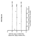
- FIG. 19 shows blood separation and plasma collection membranes do not significantly bind p24 protein analyte.
- FIG. 20 shows no loss of analyte-specific signal is observed in plasma collected from analyte-spiked whole blood separated with a device of the present invention.
- FIG. 21 shows no loss of analyte-specific signal is observed in plasma collected from analyte-spiked whole blood separated with a device of the present invention.
- FIG. 22 shows that signal output of collection pads dried down with assay-specific detergents is comparable to reactions with detergents in solution.
- FIG. 23 shows that signal output of collection pads dried down with assay-specific detergents and protein analyte is comparable to reactions with detergents and analyte in solution.
- FIG. 24 shows a schematic of a clam shell disposable (single-use) plastic component, part of the filter element.
- the clam shell integrates a separation filter into itself, and interface with an external plasma collection element, which contains the collection membrane.
- FIG. 25 shows (a) the top-half of a clam shell is folded over and closed. The left and right latching tabs lock and hold the clam shell closed, as shown in the section-view schematic in (b).
- FIG. 26 shows (left) a schematic of the clam shell plastic part.
- a separation filter is aligned and bonded to the clam shell, here, via the energy director using ultrasonic welding; and (right) a schematic of the integrated clam shell and separation filter.
- the energy director plastic melts and flows into the separation filter, creating a pseudo ring barrier.
- FIG. 27 shows (left) a schematic of a closed and locked clam shell, which has a separation filter bonded to it (e.g., via ultrasonic welding using an energy director); and (Right) a section-view of the left schematic showing that the separation filter is bonded such that when the clam shell is closed, it is flush with the bottom-half of the clam shell.
- FIG. 28 shows (a) top-view schematic of the plasma collection element, a plastic substrate test strip holds a small piece of double-sided diagnostic compatible adhesive, which bonds the collection membrane to the substrate test strip; (b) side view of the collection element; (c) exploded view of the side-view (red dashed box) showing the crease, perforation, and thin adhesive layer bonding the substrate test strip and collection membrane.
- FIG. 29 shows (left) schematics of both the plasma collection element and filter element with their respective membrane and filter; and (right) the collection element slid into the filter element via the slot and aligned with the back wall.
- FIG. 30 shows (left) a schematic of the collection element integrated with the filter element, where the top-half of the clam shell has been folded down and locked via the locking tabs; (right) this allows the separation filter and collection membrane to overlap and compress together, which facilitates the blood separation.
- FIG. 31 shows (left) a schematic showing the assembled module for blood separation; and (right) a transparent side-view of the assembled module showing the lip engaging with the crease in the collection element substrate test strip.
- FIG. 32 shows a step-by-step overview of the blood separation process using a clam-shell filter element and plasma collection element: (a) dispense blood sample onto separation filter; (b) the separation filter passes the plasma through to the collection membrane; (c-d) the operator squeezes the bottom-half of the left and right locking tabs to unlatch the top-half of the filter element; and (d) the filter element and collection element are separated from one another and may be used for subsequent test processes (e.g., CD4 count, PCR, immunoassay)
- test processes e.g., CD4 count, PCR, immunoassay
- the term “subject” refers to organisms to be treated by the methods of the present invention. Such organisms preferably include, but are not limited to, mammals (e.g., murines, simians, equines, bovines, porcines, canines, felines, primates, etc.), and most preferably humans.
- the term “subject” typically refers to one who has had provided a sample, or had a sample taken (e.g., tissue sample, fluid sample (e.g., blood sample)).
- tissue sample e.g., fluid sample (e.g., blood sample)
- patient is commonly used when referring to a human subject.
- diagnosis refers to the recognition of a disease by its signs and symptoms (e.g., resistance to conventional therapies), or genetic analysis, pathological analysis, histological analysis, and the like.
- in vitro refers to an artificial environment and to processes or reactions that occur within an artificial environment.
- in vitro environments include, but are not limited to, test tubes.
- in vivo refers to the natural environment (e.g., an animal or a cell) and to processes or reaction that occur within a natural environment.
- sample as used herein is used in its broadest sense.
- a sample may comprise a cell, tissue, or fluids (e.g., blood, plasma, etc.), material isolated from a cell, genomic DNA (in solution or bound to a solid support such as for Southern blot analysis), RNA (in solution or bound to a solid support such as for Northern blot analysis), cDNA (in solution or bound to a solid support) and the like.
- to isolate or “isolated” refer to a sample that is identified and separated from at least one component or contaminant with which it is ordinarily associated in its natural source.
- An isolated sample is such present in a form or setting that is different from that in which it is found in nature.
- a non-isolated sample is found in the state they exist in nature.
- the terms “purified” or “to purify” refer to the removal of components (e.g., contaminants, undesired components) from a sample.
- the term “substantially purified” refers to molecules that are at least 60% free, preferably 75% free, and most preferably 90%, 95%, 99%, or more, free from other components with which they usually associated.
- the present invention provides systems, devices, kits, and methods for separating blood plasma from whole blood.
- the present invention provides systems, devices, and methods for separating a volume (e.g., fixed volume) of blood plasma from whole blood with minimal energy input.
- the present invention provides systems and devices for separating blood plasma from whole blood.
- devices separate blood plasma from other blood components (e.g., blood cells).
- devices purify blood plasma.
- devices isolate blood plasma.
- devices concentrate blood plasma.
- devices effectively separate and concentrate a fixed volume of plasma from whole blood.
- the present invention separates, isolates, purifies, and/or concentrates blood plasma from whole blood without additional energy input (e.g., no requirement for heating, centrifuging, electricity, etc.).
- the present invention provides a filter element, and a collection element.
- whole blood e.g., unfiltered
- the blood is drawn (e.g., by capillary action, by gravity, etc.) through the filter element toward the collection element.
- the present invention provides a filter element.
- one or more blood components e.g., cellular components
- blood components other than plasma e.g., cellular components
- one or more blood components are unable to move through the filter element.
- blood components other than plasma e.g., cellular components
- blood plasma rapidly (e.g., more rapidly than other blood components) advances through the filter element toward and/or into the collection element.
- the filter element comprises a filter, membrane, matrix, and/or pad capable of separating blood plasma from other blood components based on capillarity.
- d (2 ⁇ cos ⁇ )/( ⁇ gr ) wherein ⁇ is the liquid-air surface tension (energy/area), ⁇ is the contact angle, ⁇ is the density of liquid (mass/volume), g is acceleration due to gravity (length/time 2 ), and r is radius path through the material (length).
- a filter element comprises a filter and/or membrane configured to allow passage of blood plasma and other whole blood components at different rates.
- a filter element comprises a plasma separation membrane.
- a filter element comprises a VIVID Plasma Separation Membrane.
- a filter element comprises a VIVID GF Plasma Separation Membrane.
- a filter element is configured to separate a defined volume of whole blood (e.g., 15 ⁇ L, 25 ⁇ L, 50 ⁇ L, 75 ⁇ L, 100 ⁇ L, 125 ⁇ L, 150 ⁇ L, 200 ⁇ L, 300 ⁇ L, 400 ⁇ L, 500 ⁇ L, 750 ⁇ L, 1 mL, 2 mL, 3 mL, etc.).
- filter element comprises a membrane of any suitable size.
- filter element comprises a membrane of any suitable diameter (e.g., 5 mm . . . 8 mm . . . 10 mm .
- a filter element is disposable.
- a filter element is reusable.
- a filter comprises a molded clam shell (e.g., disposable molded clam shell) (SEE FIGS. 24-25 ).
- a filter element comprises a shell (e.g., single-use shell) and a separation filter (SEE FIGS. 26-27 ).
- a clam shell component is injection molded (e.g., from a molded plastic resin).
- a filter element comprises a clam shell component integrated with a separation filter.
- the present invention is not limited by the materials or configuration used in the filter element, and any material understood by one in the field to provide suitable filtration qualities may find use with the present invention.
- a collection element comprises a substrate, pad, matrix, material, and/or filter.
- a collection element is configured to collect a fixed volume of plasma from a whole blood sample (e.g., 10 ⁇ L, 20 ⁇ L, 30 ⁇ L, 40 ⁇ L, 50 ⁇ L, 60 ⁇ L, 70 ⁇ L, 80 ⁇ L, 90 ⁇ L, 100 ⁇ L, 200 ⁇ L, 300 ⁇ L, 400 ⁇ L, 500 ⁇ L, 1 mL, etc.).
- a collection element comprises a plasma separation membrane, collection pad, collection matrix, etc.
- a collection element comprises one or more of glass fiber, polyester, nitrocellulose and/or cellulose.
- a collection element comprises one or more materials selected from WHATMAN Fusion 5 (Whatman Diagnostic Catalogue 2010, page 8; herein incorporated by reference in its entirety), PALL ACCUWICK, PALL A/D, AHLSTROM 111 (Ahlstrom Laboratory Products Catalog (2009), page 15; herein incorporated by reference in its entirety), AHLSTROM 151 (Ahlstrom Laboratory Products Catalog (2009), page 15; herein incorporated by reference in its entirety), and/or AHLSTROM 142 (Ahlstrom Laboratory Products Catalog (2009), page 15; herein incorporated by reference in its entirety) membranes, and/or any other suitable membranes, pads, or matrix materials known to those of skill in the art.
- a collection element comprises an AHLSTROM 142 collection membrane.
- filter element comprises a membrane of any suitable diameter (e.g., 2 mm . . . 4 mm . . . 6 mm . . . 8 mm . . . 10 mm . . . 12 mm . . . 15 mm . . . 20 mm . . . 30 mm . . . 40 mm . . . 50 mm, etc.).
- a collection element comprises a substrate test strip, diagnostic double-sided adhesive, and collection membrane.
- a collection element comprises a collection membrane.
- a collection element comprises a diagnostic double-sided adhesive. In some embodiments, a collection element comprises a substrate test strip. In some embodiments, a collection element comprises a substrate test strip, diagnostic double-sided adhesive, and collection membrane.
- the present invention is not limited by the materials used in the collection element or its configuration, and any material or configuration understood by one in the field to provide suitable collection qualities may find use with the present invention.
- a filter element and collection element comprise a single unit. In some embodiments, a filter element and collection element comprise separate collection and filter modules. In some embodiments, a separation module and filter module are operable connected and/or connectable. In some embodiments, a filter module comprises a filter element. In some embodiments, a filter element (e.g., membrane) in a filter module is replaceable and the filter module is reusable with a new filter element (e.g., membrane). In some embodiments, a collection module comprises a collection element. In some embodiments, a collection element (e.g., membrane) in a collection module is replaceable and the collection module is reusable with a new collection element (e.g., membrane).
- a filter element e.g., membrane
- the present invention provides a matrix within a collection module to collect blood (e.g., from a finger-stick, from a vein, etc.). In some embodiments, the present invention provides a matrix to collect blood from a finger-stick. In some embodiments, the present invention separates cells from plasma when whole blood is added. In some embodiments, the amount of blood required is minimized by maximizing the efficiency of plasma separation.
- devices of the present invention provide separation of whole blood components (e.g., blood cells) from plasma.
- the separated plasma and cellular components can each be used for subsequent applications (e.g., testing).
- cellular blood components are separated from plasma to monitor CD4 count, and the plasma component is used for measuring viral load.
- devices of the present invention provide samples for multiple different assays (SEE FIG. 7 ).
- systems, devices, and methods provide timed separation of plasma components from cellular components in whole blood.
- separation of plasma from other blood components is complete in less than 1 hour (e.g., 45 minutes . . . 30 minutes . . . 20 minutes . . . 15 minutes . . . 10 minutes . . . 8 minutes . . . 6 minutes . . . 5 minutes . . . 4 minutes . . . 3 minutes . . . 2 minutes . . . 1 minutes . . . 30 seconds).
- systems, devices, and methods collect a fixed amount of plasma. In some embodiments, systems, devices, and methods collect a fixed amount of plasma on a membrane, filter, and/or pad (e.g., ALLSTOM 142). In some embodiments, the present invention collects a fixed volume of plasma and therefore provides a measuring device. In some embodiments, devices of the present invention collect a fixed volume of plasma, independent of the volume of blood added. In some embodiments, devices of the present invention collect a fixed volume of plasma, independent of the hematocrit of the blood added.
- systems, devices, and methods of the present invention collect a fixed volume of plasma from a whole blood sample (e.g., 10 ⁇ L, 20 ⁇ L, 30 ⁇ L, 40 ⁇ L, 50 ⁇ L, 60 ⁇ L, 70 ⁇ L, 80 ⁇ L, 90 ⁇ L, 100 ⁇ L, 200 ⁇ L, 300 ⁇ L, 400 ⁇ L, 500 ⁇ L, 1 mL, etc.). In some embodiments, systems, devices, and methods of the present invention collect approximately 50 ⁇ L of blood plasma.
- devices of the present invention provide collection of a volume of plasma selected to provide a desired viral load in the sample (e.g., a volume of 50 ⁇ L provides an assay sensitivity of 600 HIV copies/mL of blood for HIV viral load detection by RT-PCR).
- a volume of plasma selected to provide a desired viral load in the sample (e.g., a volume of 50 ⁇ L provides an assay sensitivity of 600 HIV copies/mL of blood for HIV viral load detection by RT-PCR).
- devices, systems, and methods of the present invention operate passively, not requiring any active pumping, centrifugation, electrophoresis, and/or electricity to operate.
- passive separation is achieved via capillary action and/or gravity.
- devices, system, and methods of the present invention provide plasma separation in non-laboratory, remote locations (e.g., in the field), and/or point-of-care location
- a collection element e.g., membrane
- the separation element e.g., membrane
- a device and/or system in which the collection element (e.g., membrane) is smaller than the separation element (e.g., membrane) serves to concentrate plasma into a small volume.
- concentration of blood plasma into a small collection element is useful for downstream analytical steps that require increased sensitivity (e.g., an immunoassay, or for improved nucleic acid capture onto a paramagnetic particle).
- a device of the present invention, a collection element, and/or a collection module provide and/or serve as a blood plasma storage element.
- the present invention provides a blood plasma storage element.
- blood plasma is stored in the collection element (e.g., collection matrix).
- plasma is transported while contained within the collection element.
- a filter element containing filtered blood components is discarded prior to storage and/or transportation of blood plasma.
- a device of the present invention a collection element, and/or a collection module is integrated with downstream processes (e.g., a cartridge or other device for HIV viral RNA extraction, purification and amplification; a lateral flow system for the detection of HIV antibodies or p24 protein; etc.).
- a device or system of the present invention comprises downstream modules for analysis or further manipulation of separated blood plasma.
- a collection element allows extraction of collected plasma directly into buffer for further analysis and/or manipulation.
- the plasma collection membrane allows for the extraction of the viral RNA present in the plasma directly into buffer (e.g., Ambion lysis/binding buffer (Applied Biosystem)) for further down-stream processing.
- direct extraction from the collection element eliminates handling steps associated with other protocols which can result in loss, contamination, or damage of the sample.
- the plasma collection membrane allows for the extraction of proteins (e.g., HIV-specific antibodies, p24 core proteins, etc.) for further downstream processing.
- assay reagents can be stored (e.g., dried or lyophilized) in the plasma collection module.
- a collection element provides a matrix for storage (e.g., long term storage) of paramagnetic particles (PMPs).
- PMPs which are used for capture nucleic acids (e.g., viral RNA) and subsequent processing.
- a collection element allows the PMPs to be extracted out of the membrane using a magnetic force (e.g., generated by a permanent magnet or an electro-magnet), eliminating the need for solution agitation and centrifugation, steps typically associated with samples collected in filter membranes for PCR applications.
- a magnetic force e.g., generated by a permanent magnet or an electro-magnet
- kits comprising one or more or all of the components necessary, sufficient, or useful for making or using any of the devices described herein.
- kits comprise control reagents, instructions (e.g., software), data analysis devices, or any other desired components.
- this method exhibited the following limitations: (1) the flow rate was slow making the process time consuming, (2) the position of the blood front varied with hematocrit, volume of blood added, and other rheological properties of the blood, requiring the user to manually locate the blood front and cut the membrane to separate the plasma from the whole blood (3) collecting a fixed volume of plasma would also require punching out a fixed length of plasma containing membrane, which depends on the capacity of the membrane.
- Plasma separation was carried out in a vertical-flow configuration (SEE FIG. 3 ). Red and white blood cells are captured by the separation membrane due to its small pore size whereas the plasma component of blood flows through to the collection membrane.
- the plasma flow rate, Q is directly proportional to the cross-sectional area of flow and inversely proportional to the length of flow. Due to the large cross-sectional area and small length of flow compared to lateral flow, separation of plasma from cells is faster in vertical flow than in lateral flow.
- Membranes were selected based on several criteria, e.g., efficiency of plasma extraction from whole blood, and ease of RNA extraction from the membrane in the lysis/binding buffer (Applied Biosystem, Carlsbad, Calif.) containing ethanol and guanidinium thiocyanate (GuSCN). Experiments were performed during development of embodiments of the present invention to determine the efficiency of plasma separation from whole blood, and sample collection, for selected membranes (SEE FIG. 3 ). PALLCytosep 1662, Whatman VF1 and PALL VIVID GR were tested for plasma separation and Ahlstrom 111, Ahlstrom 142, Whatman MF1 and PALL ACCUWIK Ultra were tested for sample collection.
- the separation membrane was sized for 100 ⁇ L of blood using the manufacturer's recommendations.
- the collection membrane was sized for 50 ⁇ L of plasma using the manufacturer's recommended membrane capacity.
- a fresh blood sample containing anti-coagulating agent was used.
- the hematocrit of the blood sample was adjusted to 50% by aliquoting a known amount of plasma and cells into a microfuge tube.
- the plasma and cells were mixed well by pulling it on a shaker for 20 minutes.
- the filter membranes were weighed and then configured for testing (SEE FIG. 3 ). Pressure was applied by adjusting the screws to provide contact between the membranes. 100 ⁇ L of blood was added to the separation membrane, which was allowed to stand for 10 minutes. The collection pad was subsequently weighed again.
- Plasma volume collected was calculated by taking the difference between the pre and post filtered weights and dividing by the density of plasma.
- the density of plasma was estimated to be 1025 kg/m 3 (Benson K: MCAT review. Emory University 1999:141-199., herein incorporated by reference in its entirety), which is an approximate average value.
- the plasma recovery was then calculated by dividing the plasma volume collected by the total amount of plasma in the original sample.
- the separation and collection membrane were disposed off in a biohazard container. The set-up is washed with 70% ethanol, dried and then used for further studies.
- Capillary number or pore size of the collection membrane affects the efficiency of extraction.
- the separation membrane should separate plasma without gelling fouled or clogged, its capacity should be minimal. A membrane with a high liquid capacity would lead to lower efficiency of extraction in the collection membrane.
- the VF1 membrane consists of pores of various sizes and merely retards the flow of membrane. Given sufficiently long times (>10 minutes), the cells eventually leak out of the membrane into the collection pad.
- the VF1+G934-AH membrane is a combination of a separation pad and a barrier membrane and only works with collection membranes of small pore sizes such as 111.
- the barrier membrane has a small pore size of 3 ⁇ m and prevents the cells from crossing.
- the VF1 is important to prevent the barrier membrane from getting clogged.
- MF1 as a collection membrane slows down the flow sufficiently to prevent any red blood cells from creeping into the collection membrane, but it reduces the efficiency of extraction as well.
- the VF1 membrane was submerged in a 2% solution of a polycation, Merquat 550 (Nalco Company, IL) (SEE FIG. 4 ).
- RNA extraction from the sample collection membrane in the lysis/binding buffer.
- the efficiency of nucleic acid efficiency may be affected by the nucleic acid binding to the RNA in the presence of the lysis/binding buffer containing a high concentration of GuSCN and isopropanol.
- Membranes with extremely small pore sizes may allow viruses to diffuse into the membrane from the separation membrane, but may not allow the viral RNA from the lysed virus to diffuse out of it once the membrane is submerged in the lysis/binding buffer.
- the separation membrane was sized for 50 ⁇ L of plasma using the manufacturer's recommendations. HIV-1 virus, acquired from Rush Virology Quality Assurance Laboratory at 1.5 ⁇ 106 copies/mL of plasma, was diluted in seronegative plasma to obtain HIV-1 concentrations of 300 copies/ ⁇ L. The plasma sample containing HIV was added to the filter membrane and allowed to sit for 5 minutes. The filter membrane was put into a microfuge tube and 600 ⁇ L of lysis buffer was added to it and vortex mixed for 10 minutes.
- RNA All the membranes captured some of the RNA (Table 2).
- the PALL ACCUWIK retains the least amount of RNA and also shows the least variability of the amount of RNA capture.
- the glass fiber membranes and the cellulose membranes bind to RNA in the presence of the lysis buffer.
- RNA in Ahlstrom 142 was separated using the set-up described in FIG. 3 . Whatman VF1 was used for separation of cells and Ahlstrom 142 was used for plasma collection. The RNA was extracted and amplified using the protocol described above. As a control, plasma containing HIV-1 was also purified and amplified using the IPF protocol. A 1.5 Ct difference would be expected between the plasma sample and the sample captured on Ahlstrom 142 based on the results shown in Table 2, however, an extra loss of 0.5 Ct was observed (SEE FIG. 4 ). The additional loss was caused by the loss of viral particles in VF1. A similar study carried out with plasma separated using VF1 containing Merquot gave no results indicating that the virus was captured by the positively charged merquot or the merquot which gets carried over with the plasma inhibits the PCR even after IPF purification.
- HIV-1 virus acquired from Rush Virology Quality Assurance laboratory at 1.5 ⁇ 106 copies/mL of plasma, was diluted in seronegative plasma to obtain HIV-1 a concentration of 300 copies/ ⁇ L.
- the plasma sample was speared on the swab, and the swab was dipped into a microfuge tube containing 400 ⁇ L of Ambion lysis buffer, bead mix was added, and the sample was mixed by vortexing gently for 4 minutes and allowed to stand for an additional 2 minutes.
- the PMPs were removed using a pick pen and put into a solution containing 200 ⁇ L of Ambion lysis buffer also pipetted out from the above microfuge tube.
- the Immiscible Phase Filter (IPF) purification was carried out.
- HIV-1 viral load quantification was performed using the Abbott RealTime HIV-1 Amplification Reagent Kit (Abbott Molecular, Des Plaines, Ill.) in 25 ⁇ L reaction volumes with the addition of 0.2 mg/mL bovine serum albumin (Sigma), 150 mM trehalose (Sigma) and 0.2% Tween 20 (Pierce Thermo Fisher Scientific) and 5 ⁇ L template. Amplification reactions were performed in Cepheid SmartCycler II (Sunnyvale, Calif.).
- the swabs are hydrophobic in nature and do not absorb easily. Due to the porous structure of the flocks, it has a low wicking capability. It would however be suitable for more viscous samples.
- the swab also absorbs RNA and a C T difference of 2.0 was observed between the samples put on the swab and the positive control where the sample was put into the lysis buffer. This indicates that three-fourth of the RNA was absorbed on the swabs. Washing the swab with water, ethanol or lysis buffer before the test did not change the results.
- the PMPs also tend to aggregate when they come in contact with the swab.
- HIV-1 virus acquired from Rush Virology Quality Assurance laboratory at 1.5 ⁇ 106 copies/mL of plasma was smeared on the swab.
- the swab was dipped in 300 ⁇ L of Ambion elution buffer (Applied Biosystem; Foster City, Calif.), and allowed to stand for a minute. As much liquid as possible was removed from the swab. 800 ⁇ L of Ambion lysis buffer was added to the above stated buffer containing the plasma samples. 800 ⁇ L is used instead of 400 ⁇ L since the sample volume is large (350 ⁇ L). A large volume of elution buffer was used, so that the swab could be completely submerged in the buffer.
- HIV-1 viral load quantification was performed using the Abbott RealTime HIV-1 Amplification Reagent Kit (Abbott Molecular, Des Plaines, Ill.) in 25 ⁇ L reaction volumes with the addition of 0.2 mg/mL bovine serum albumin (Sigma), 150 mM trehalose (Sigma) and 0.2% Tween 20 (Pierce Thermo Fisher Scientific) and 5 ⁇ L template Amplification reactions were performed in Cepheid SmartCycler II (Sunnyvale, Calif.) using the Roche TtH.
- the plasma sample containing HIV-1 virus was added directly to 300 ⁇ L of Ambion elution buffer without being applied on a swab.
- As a negative control HIV-1 negative plasma is applied to the swab. Controls were processed in the same manner as the samples.
- RNA or viral particles are absorbed in the swab.
- Sample Cycle Threshold (C t) Positive control 19.75 Sample-1 on swab 20.91 Sample -2 on swab 21.2 Negative sample on swab 0 POSITIVE CONTROL DENOTES A PLASMA SAMPLE CONTAINING HIV-1, SAMPLE -1 ON SWAB AND SAMPLE-2 ON SWAB DENOTE PLASMA SAMPLES CONTAINING HIV-1 AND NEGATIVE SAMPLE ON SWAB DENOTES A SERONEGATIVE PLASMA SAMPLE ON THE SWAB.
- Pillar chips are symmetric and do not show the variability in pore diameter associated with filter membranes. They are made of plastic and are commonly used as micro-prismatic reflective sheeting for high-brightness traffic signs (10 ⁇ Technology, Libertyville, Ill.). The technology can be modified to create low-cost pillar chips (e.g., SEE FIG. 6 ). Preliminary studies showed that their capacity per unit area was low due to the large base diameter and the short height of the pillar, making them unsuitable for a high volume application such as this one. However, pillar chips could find utility in set-ups which require ⁇ 25 ⁇ L of sample.
- the VIVID Plasma Separation membrane is an asymmetric, hydrophilic, polysulfone membrane with low biomolecule binding.
- the asymmetric nature of the material allows the cellular components of blood (red cells, white cells, and platelets) to be captured in larger pores while permitting plasma to flow freely to the other side of the membrane through smaller pores.
- the cellular components are filtered without lysis, removing their contaminants completely from the plasma sample. Since cellular components are collected within the membrane, it is important to size the VIVID paper so that plasma flow is not hindered by clogged pores.
- the blood volume capacity of VIVID is defined as the amount of whole blood per square centimeter of medium that can be rapidly and effectively separated with low hemolysis.
- Blood volume capacity is directly related to the void volume of the material and is defined as 40-50 ⁇ L per square centimeter for the GR grade of material.
- the VIVID GR is rated for ⁇ 80% plasma recovery. An average patient with 50% hematocrit would need to supply 125 ⁇ L of whole blood to be able to collect 50 ⁇ L of plasma. Therefore, to ensure that no clotting or lysis occurs, the VIVID membrane must be 2.5 square centimeters in area which corresponds to an 18 mm diameter circular punch.
- the ACCUWIK is used to collect the fixed amount of plasma.
- the absorption capacity as defined by Pall Life Sciences is 38 ⁇ L per square centimeter, which corresponds to a 12.9 mm diameter circular punch for a 50 ⁇ L plasma sample.
- This small size of the ACCUWIK relative to the size of the separating membrane (VIVID) allows concentration the plasma into a small volume.
- the porous ACCUWIK provides a matrix for easy transport of liquid and for further chemical assays within the matrix.
- the absorbance capacity of the ACCUWIK Ultra was measured in ⁇ L per square centimeter by adding a fixed volume of plasma and measuring the resulting welled area.
- the ACCUWIK Ultra medium is a hydrophilic fibrous membrane made out of hydroxyiated polyester and characterized by uniform uptake and rapid release. ACCUWIK strips were cut using a commercially available paper cutter. The width of each strip was measured and recorded. The length of each strip was approximately 100 mm. 50 ⁇ L of plasma was added to the end of the strips and allowed to wick laterally until the front edge stopped moving. The length of the welled area was measured and recorded.
- the plasma collection and separation unit comprises two parts: the cell separation module and the plasma module.
- the cell separation module houses the VIVID filter, while the plasma module contains the ACCUWIK membrane (SEE FIG. 7 ). Once assembled, the ACCUWIK membrane lies in direct contact with the VIVID filter, providing capillary force to wick the plasma from the membrane. The contact pressure is established by the positioning of the plasma module with respect to the cell separation module.
- the whole blood sample is added through the opening in the top of the device and placed directly on the VIVID membrane. After an adequate amount of time has passed the plasma module is unscrewed from the cell separation module and inserted into the test cartridge for further processing. The cell separation module containing the filtered material can then be properly discarded.
- the first generation system was machined out of polypropylene (SEE FIG. 8 ).
- Polypropylene was selected because it is chemically inert. However, polypropylene does exhibit poor machining properties.
- the filter membrane is attached to the modules by a double sided adhesive. While several methods of adhesion may find use with a device of the present invention, e.g., sonic welding, heat sealing, laser welding, mechanical clamping, etc, adhesive was selected for the first generation device as it allows the plastic module to be reused.
- the adhesive exhibited excellent bond strength to most surfaces including low surface energy plastics such as polypropylene.
- the O-ring in the collection module forms a tight seal and holds the two modules together due to a friction fit.
- Preliminary studies conducted during development of embodiments of the present invention demonstrated that it was difficult to accurately control the contact between the two membranes in this set-up which led to variable plasma separation efficiency. Contact pressure was therefore identified as a key parameter to be optimized for consistent and efficient plasma separation.
- Second generation modules were machined out of polypropylene to integrate a screw lock mechanism which allowed for accurate positioning of the filter membrane with respect to each other (SEE FIG. 9 ).
- an anti-rotation insert was designed (SEE FIG. 9 ).
- the cell separation module has a fastening dowel pin projecting inwards.
- the anti-rotation insert has a notch in which the dowel pin sits. This prevents the anti-rotation insert from rotating, but allows it to move up and down freely. The vertical motion is still achieved by rotating the screw positioning device shown in the figure.
- Each cell separation module and the corresponding screw position device are labeled to allow the two to be coupled.
- the distance d shown in FIG. 10 is 1 mm.
- the numbers engraved on the cell separation module and the corresponding screw module device lie on the same vertical axis.
- the distance “d” is maintained.
- Filter papers and adhesives were cut to the appropriate size using a laser cutter machine.
- Cell separation and plasma modules were washed in 70% EtOH and allowed to dry.
- the 12 mm round adhesive cut out was used to adhere the 12 mm ACCUWIK cut out to the anti rotation insert.
- the anti-rotation insert and ACCUWIK were weighed on a balance and the weight was recorded.
- the anti-rotation insert was then placed in the cell separation module and the screw positioning piece was screwed into the cell separation module from the bottom. Etched numbers on both the cell separation module and screw positioning piece were used to establish position with one full turn corresponding to 1 mm of vertical movement.
- the anti-rotation piece was first placed well below the VIVID platform on the cell separation module to allow the 18 mm VIVID cut out to be adhered.
- the 18 mm adhesive ring was used to adhere the 18 mm VIVID to the cell separation module using the edges as a guide.
- the screw positioning device was then used to position the ACCUWIK at distances of ⁇ 0.5 mm, 0 mm, 0.25 mm and 0.5 mm from the bottom surface of the VIVID membrane.
- the distance, d is defined as the distance between the bottom surface of the VIVID and the top surface of the anti rotation piece (bottom surface of the ACCUWIK) (SEE FIG. 10 ).
- the upward direction is negative.
- 125 ⁇ L of whole blood (50% Hematocrit) was added to the VIVID.
- 50% hematocrit was achieved by spinning whole blood samples in a centrifuge (4000 ⁇ ) for 10 minutes, transferring all of the plasma to a new tube and adding the same volume of cellular components to the plasma sample. Enough 50% hematocrit blood was prepared so that the same blood source was used for all tests. The sample was allowed to filter for 10 minutes. The VIVID membranes were then removed and properly discarded in a biohazard container. The anti-rotation piece was also removed and weighed on the balance. The weight was recorded. The ACCUWIK membrane was then disposed of in a biohazard container. Plasma volume collected was calculated by taking the difference between the pre and post filtered weights and dividing by the density of plasma. The density of plasma was assumed to be 1025 Kg/m 3 . The plasma recovery was then calculated by dividing the plasma volume collected by the total amount of plasma in the original sample, which in this instance was 57.5 ⁇ L, and multiplying by 100.
- the 0 mm and 0.25 mm distances produced the highest plasma recovery of 52 ⁇ L and 53 ⁇ L. However, at a distance of 0.25 mm, the variability (standard deviation) was 5.9111 compared to 0.9411 at 0 mm.
- the ACCUWIK membrane may no longer be in contact with the VIVID membrane and therefore, does not collect as much plasma as a result of the decrease in capillary force.
- the ⁇ 0.5 mm distance meaning the ACCUWIK is fully compressed against the VIVID
- a high plasma recovery was observed; however, the plasma recovery was not as high at the other two distances.
- the volume of blood obtained from a particular lancing device is dependent on three major factors: physical/mechanical (e.g., the lancing device itself), biological (e.g., the thickness of the skin, the subject's hematocrit, the subject's weight, the amount and potency of clotting factors in the subject's blood, etc.), and process (e.g., position of lancet, ability to maintain good contact between the lancet and the skin during the lancing process, etc.). While the volume of blood collected is variable, in some embodiments, methods, systems, and devices must collect constant volume of plasma in order to quantitatively measure the constituents of plasma, e.g., HIV-1 viral copies in plasma.
- the present invention provides a simple, low-cost, device to collect a fixed amount of plasma, independent of the volume of the original sample (e.g., the amount of blood obtained from a finger stick).
- the present invention provides a wick (e.g., ACCUWIK) which is sized to collect a fixed amount of plasma, leaving the rest of the plasma on the VIVID GR membrane.
- a wick e.g., ACCUWIK
- the present invention provides a low cost device which permits blood to be collected directly onto a filter paper, rather than a capillary tube,
- C T changes from 25.49 to 25.56, when the blood added to the blood-plasma device changes from 125 ⁇ L to 175 ⁇ L. This is well within the accepted range of +0.5 specified for our test device.
- hematocrit is the proportion, by volume, of the blood that consists of red blood cells.
- a normal hematocrit level varies significantly with gender, age, health, etc. Given a fixed volume of blood, changes in hematocrit levels affect the amount of available plasma for purification. It also affects the viscosity of the blood, thereby affecting flow rate through a device.
- the PALLVIVID Plasma Separation GR membrane is a highly asymmetric membrane which separates red blood cells from plasma by size exclusion filtration. Therefore, high hematocrit levels can clog up the membrane leading to poor plasma separation.
- the results show that the blood-plasma module can successfully separate plasma at different hematocrit levels without any clogging of the VIVID Plasma Separation GR membrane.
- the volume of plasma collected drops with increasing hematocrit due to reduced amount of plasma in the sample.
- 125 ⁇ L of blood contains only 50 ⁇ L of plasma. Therefore, the collected plasma is also lower.
- the available plasma is 106.25 ⁇ L.
- only 51.3 ⁇ L collects in the plasma module, since the PALL ACCUWIK membrane is saturated and does not allow more plasma to flow into the module.
- Fresh blood was obtained from Northwestern Memorial Hospital for this study.
- the blood sample was made homogenous by putting the tube on a rotating shaker for 2 minutes.
- the hematocrit of the blood samples was measured by spinning 30 ⁇ L of the blood in a Light Cycler PCR Tubes (F. Hoffmann-La Roche Ltd, Basel, Switzerland) at 3000 rpm for 10 minutes.
- the hematocrit was measured.
- 125 ⁇ L of blood was added and plasma was collected.
- the plasma separation and collection module successfully separated plasma from different blood samples (SEE FIG. 14 ).
- the average volume of plasma collected from 125 ⁇ L of plasma was 49.5 ⁇ L.
- the standard deviation of the volume of plasma collected is 3.35 ⁇ L. It was observed that the separation efficiency was significantly better with freshly collected blood and decreased as the blood sample got older. All tests were carried out with blood samples collected by venal puncture in a vacuum tube containing an anti-coagulant.
- Plasma samples for either processing technique were prepared by separating blood cells and plasma from blood, by centrifugation at 3500 rpm for 10 minutes. The proportion of cells and plasma to be mixed together to reconstitute a blood sample with a hematocrit percentage of 45 was calculated. Plasma was spiked with HIV-1 virus obtained from Northwestern Memorial Hospital (stock concentration of 1500 copies/ ⁇ L of plasma) to obtain a concentration of 300, 60 and 12 copies/ ⁇ L respectively. Blood was reconstituted using this plasma and cells by mixing them in a proportion 45% cells and 55% plasma.
- 125 uL of the above blood was added to the VIVID membrane of the plasma collection and separation module and allowed to stand for 10 minutes to allow the plasma to separate.
- the VIVID was carefully removed.
- the ACCUWIK was inserted into a microfuge tube (Tube-1) containing 400 ⁇ L of Ambion Lysis buffer containing Ambion Binding/Lysis Concentrate, isopropyl alcohol and Ambion Carrer RNA.
- elution buffer 50 ⁇ L was aliquoted into the smaller chamber of the IPF cartridge and the two aqueous fluids were overlaid as shown in FIG. 15 .
- the automated system aggregated the PMPs for 2 minutes using the external magnet and moved the aggregate from the lysis buffer to the elution buffer.
- the elution buffer containing the PMPs was heated to 55° C. for 10 minutes to elute the RNA.
- the PMPs were aggregated and removed from the elution buffer.
- HIV-1 viral load quantification was performed using the Abbott RealTime HIV-1 Amplification Reagent Kit (Abbott Molecular, Des Plaines, Ill.) in 25 ⁇ L reaction volumes with the addition of 0.2 mg/mL bovine serum albumin (B8667, Sigma), 150 mM trehalose (T9531; Sigma) and 0.2% Tween 20 (28320; Pierce Thermo Fisher Scientific) and 5 ⁇ L template. Amplification reactions were performed in Cepheid SmartCycler II (Sunnyvale, Calif.). Each viral load was run in quadruplets.
- the plasma containing the HIV-1 virus is separated into the ACCUWIK membrane through the VIVID membrane.
- This membrane is subsequently inserted into the tube containing the lysis buffer, whereby the virus is lysed and the viral RNA binds to the PMPs.
- the viral RNA diffuses out of the paper into the lysis buffer containing the PMPs.
- the solution containing the paper is agitated. A portion of the RNA is lost in the paper due to absorption on the membrane fibers.
- the PMPs are pre-dispensed in the ACCUWIK.
- the virus and the PMPs are both located in the porous matrix of the ACCUWIK membrane.
- the viral RNA can immediately bind to the PMPs without having to diffuse out of the paper.
- the membrane therefore acts as a matrix for reagent storage and subsequent RNA capture.
- the magnetic particles are extracted out of the paper using an inexpensive permanent magnet or an electro-magnet. This process eliminates the need for agitation, heating and centrifugation associated with the extraction of RNA from filter. Also, it provides a convenient location for reagent storage for point of care applications.
- PMPs from the Ambion Magmax kit were aliquoted in a microfuge tube and put on a magnetic stand to collect the PMPs. The liquid was removed and the PMPs were re-suspended in Ambion Binding Enhancer. For each test sample, 10 ⁇ L of PMPs and 10 ⁇ L of Ambion Binding Enhancer were used. A 5 ⁇ L solution containing 4% BSA and 0.4% Triton-X is added. The solution was added to a 12 mm ACCUWIK Ultra disc having an area sufficient to hold 50 ⁇ L of sample and allowed to air dry for 3 days at room temperature.
- Plasma was spiked with HIV-1 virus obtained from Northwestern Memorial Hospital (stock concentration of 1500 copies/ ⁇ L of plasma) to obtain a concentration of 300, 60 and 12 copies/ ⁇ L, respectively.
- the air dried ACCUWIK Ultra was inserted into a microfuge tube (Tube-1) and 50 ⁇ L of plasma sample were added to the paper.
- 400 ⁇ L of Ambion lysis buffer was added to the solution and this solution was allowed to sit for 6 minutes.
- the magnetic particles were removed from Tube-1 using a Pickpen-1 Magnetic tool (Sunrise Science Products Inc, San Diego, Calif.) and transferred to 400 ⁇ L of Ambion Wash Buffer-1 in Tube-2.
- the sample in Tube-2 was then processed using the IPF method (SEE FIG. 15 ).
- the sample from Tube-2 was added to the larger chamber of the cartridge and mixed for 4 minutes using the automated system.
- 50 ⁇ L of elution buffer was aliquoted into the smaller chamber of the IPF cartridge and the two aqueous fluids were overlaid with CHILLOUT liquid wax (Biorad laboratories; SEE FIG. 15 ).
- the automated system aggregated the PMPs for 2 minutes using the external magnet and moved the aggregate from the lysis buffer to the elution buffer.
- the elution buffer containing the PMPs was heated to 55° C. for 10 minutes to elute the RNA.
- the PMPs were aggregated and removed from the elution buffer.
- HIV-1 viral load quantification was performed using the Abbott RealTime HIV-1 Amplification Reagent Kit (19J (Abbott Molecular, Des Plaines, Ill.) in 25 ⁇ L reaction volumes with the addition of 0.2 mg/mL bovine serum albumin (B8667, Sigma), 150 mM trehalose (T9531; Sigma) and 0.2% Tween 20 (28320; Pierce Thermo Fisher Scientific) and 5 ⁇ L template. Amplification reactions were performed in Cepheid SmartCycler II (Sunnyvale, Calif.).
- plasma was spiked with HIV-1 virus obtained from Northwestern Memorial Hospital (stock concentration of 1500 copies/ ⁇ L of plasma) to obtain a concentration of 300, 60 and 12 copies/ ⁇ L respectively.
- 50 ⁇ L of the plasma sample containing different concentrations of HIV-1 virus was added to a microfuge tube (Tube-1).
- 400 ⁇ L of Ambion lysis buffer was added to Tube-1 and vortex mixed for 30 seconds.
- 20 ul of bead mix containing 10 ⁇ L of PMPs and 10 ul of binding enhancer was added and vortex mixed for 4 minutes.
- the magnetic particles were removed from Tube-1 using a Pickpen-1 Magnetic tool (Sunrise Science Products Inc, San Diego, Calif.) and transferred to 400 ⁇ L of Ambion Wash Buffer-1 in Tube-2.
- the sample in Tube-2 was then processed using the IPF method (SEE FIG. 15).
- the sample from Tube-2 was added to the larger chamber of the cartridge and mixed for 4 minutes using the automated system.
- 50 ⁇ L of elution buffer was aliquoted into the smaller chamber of the IPF cartridge and the two aqueous fluids were overlaid with CHILLOUT liquid wax (Biorad laboratories; SEE FIG. 15 ).
- the automated system aggregated the PMPs for 2 minutes using the external magnet and moved the aggregate from the lysis buffer to the elution buffer.
- the elution buffer containing the PMPs was heated to 55° C. for 10 minutes to elute the RNA.
- the PMPs were aggregated and removed from the elution buffer.
- HIV-1 viral load quantification was performed using the Abbott RealTime HIV-1 Amplification Reagent Kit [19] (Abbott Molecular, Des Plaines, Ill.) in 25 ⁇ L reaction volumes with the addition of 0.2 mg/mL bovine serum albumin (B8667, Sigma), 150 mM trehalose (T9531; Sigma) and 0.2% Tween 20 (28320; Pierce Thermo Fisher Scientific) and 5 ⁇ L template. Amplification reactions were performed in Cepheid SmartCycler II (Sunnyvale, Calif.). Each viral load was run in duplicates. As a negative control, HIV-1 negative plasma was used and processed in the same manner as the other samples.
- Viral RNA was purified from 50 ⁇ L of plasma spiked with HIV-1 virus.
- the purified RNA was amplified using the Abbott RealTime HIV-1 Amplification kit.
- a PCR efficiency of 107.7% was observed (SEE FIG. 17 ), indicating that the PMPs can be stored in the membrane without loss of RNA capture efficiency and be readily extracted for downstream processing.
- the loss of viral RNA in the filter membrane is minimal (SEE FIG. 18 ).
- the lateral flow system has been used in the detection and diagnosis of HIV.
- Current laboratory technologies rely on the combined and simultaneous detection of the HIV core (p24) protein and HIV-specific antibodies directed against HIV transmembrane proteins. Antibodies against these proteins consistently appear during seroconversion of HIV-infected individuals and remain throughout the course of infection.
- HIV positive infants In the first 2 months after birth, HIV positive infants have increasing viral loads but are seropositive due to inheritance of maternal HIV antibodies, making existing tests ineffective.
- HIV negative infants can be seropositive due to the same inheritance of maternal HIV antibodies. Detection of HIV in infants requires targeting the HIV core protein p24 as the principle marker for detection in order to verify their true infection state irrespective of the maternal sero-inheritance.
- Plasma separation devices were assembled using an 18 mm VIVID GF membrane and an 8 mm Ahlstrom 142 or 6 mm Pall A/D glass fiber collection pad. The collection pad was compressed 0.5 mm into the VIVID GF membrane.
- the VIVID membrane was sized to accommodate a fixed volume of blood, up to 125 ⁇ L, and the Ahlstrom/Pall membranes were sized to accommodate a fixed volume of 50 ⁇ L.
- the VIVID membrane was pre-treated with a solution containing 0.1% BSA protein, 0.5% sucrose and 0.1% Tween-20.
- test strip containing a neutravidin test line and an anti-mouse control line was added to the reaction.
- Test strips were quantified using a camera after being dried through background subtraction of the test line signal. Only marginal recovery losses (e.g., non-specific binding) of p24 were observed in the separation device fitted with an untreated VIVID membrane (SEE FIG. 19 ). For all the other samples, an equivalent output as to the reference mix and run reaction was obtained, indicating no significant loss of the analyte signal to either the VIVID membrane or the Ahlstrom collection pad.
- Separation devices were assembled and reconstituted whole blood (125 ⁇ L from the 50% Ht and 100 ⁇ L from the 35% Ht) were applied to the separation devices and plasma collected from the pad of each of these was subjected to the assay for signal readout.
- An additional reference reaction was performed whereby 50 ⁇ L of plasma containing the 1 ng/mL p24 analyte was added directly to the assay buffer and labeled mix and run.
- the amount of analyte recovered from applying both the 35% and 50% Ht blood samples is comparable to the mix and run reference reaction (SEE FIG. 20 ), indicating that this plasma separation device can be used to successfully recover protein analyte from whole blood samples with no detectable loss of analyte incurred through the separation of the cellular blood phase.
- the lateral flow assay utilizes a specific concentration of detergents, namely SDS and NP-40, in order to allow for viral (HIV) disruption and analyte (p24 protein) release from HIV infected samples.
- a specific concentration of detergents namely SDS and NP-40
- HAV viral
- p24 protein analyte
- a 50 ⁇ L plasma sample 100 ⁇ L of PBS buffer containing 0.2% SDS and 0.67% NP-40 is optimally required for virion disruption and p24 recovery.
- 10 ⁇ L of a ten-fold concentrated stock of detergent solution (2.0% SDS and 6.7% NP-40) was applied to a collection pad and allowed to dry for 24 h at room temperature.
- Evaluations were performed whereby 10 ⁇ L of a ten-fold concentrated stock of detergent solution (2.0% SDS and 6.7% NP-40) was applied to a collection pad and allowed to dry for 24 h at room temperature. Then 50 ⁇ L of plasma with or without 1 ng/mL of the p24 analyte was added to the pad and allowed to dry for 24 h at room temperature. The samples were then reconstituted with 125 ⁇ L of PBS buffer, mixed by flicking the tube containing the pad and buffer and analyzed.
- a ten-fold concentrated stock of detergent solution (2.0% SDS and 6.7% NP-40
- the assay output from the detergent/p24 dried down in the pad was comparable to solution-phase mix and run reference reaction, indicating that the dry down of the assay reagents as well as p24 protein used as a potential reference standard (positive and negative controls) for an assay is feasible and compatible in the collection pad membrane (SEE FIG. 23 ).
- the present invention provides a filter module with a clam shell design (SEE FIG. 24 ) which is closed by folding and latching the top-half via locking tabs (SEE FIG. 23 ).
- a clam-shell type filter module comprises a slot for a collection test strip designed to accept the width of the collection test strip.
- the entrance to the slot has both chamfered edges and a filleted bottom edge to assist in guiding a collection module into the clam shell without interference.
- the depth of the slot is designed such that there is an overlap between the collection membrane and separation filter (SEE FIG. 30 ).
- a clam-shell type filter module comprises locking tabs (e.g., two (left and right) locking tabs) that allow for latching the top-half closed (SEE FIG. 25 ).
- the clam shell is opened by an operator by squeezing on the bottom half of the locking tabs to pivot it open and release the top-half of the clam shell.
- a living hinge is integrated into the clam shell design.
- the plastic component of the clam shell is made from polypropylene.
- the living hinge provides the capacity to open and close the clam shell thousands of times, although the actual process only requires it to flex a few times.
- a clam-shell type filter module comprises one or more pockets (e.g. 1, 2, 3, 4, 5, 6, 7, 8, 9, 10, . . . 20).
- the pockets serve to keep uniform thickness of the molded part, which prevents warping and sink marks, e.g., due to uneven cooling.
- the wall thickness for the pockets is uniform.
- a clam-shell type filter module comprises a lip. In some embodiments, when the top-half of the clam shell is locked using the locking tabs, the lip engages with a crease in the collection modules (SEE FIG. 31 ).
- a clam-shell type filter module comprises latch guards (e.g., 4 latch guards). In some embodiments, latch guards prevent the top-half of the clam shell from sliding back and forth once it has been locked into place via the locking tabs. In some embodiments, the latch guards engage with the edges of the locking tabs (SEE FIG. 25 ). In some embodiments, a clam-shell type filter module comprises an energy director. In some embodiments, an energy director facilitates bonding of the separation filter to the clam shell via ultrasonic welding (SEE FIGS. 26-27 ).
- the triangular energy director is designed such that its height is approximately the same as the thickness of the separation filter.
- ultrasonic welding creates a pseudo ring barrier since the energy director plastic melts and flows into the separation filter. The pseudo ring barrier facilitates higher performing separations.
- the membrane is bonded using heat sealing, laser welding, adhesives, etc.
- a clam-shell type filter module comprises a back wall. In some embodiments, the back wall of the slot serves as a stopping point for positioning the collection modules. When the collection module is positioned to make contact with the back wall, the crease automatically aligns with the lip of the clam shell (SEE FIG. 31 ).
- a clam-shell type filter module is configured to connect to, function with, and/or integrate with a separation filter.
- a clam-shell type filter module is integrated with a separation filter (e.g., Pall Vivid) (SEE FIG. 26 ).
- the separation filter is any suitable filter, as described herein and elsewhere.
- the separation filter is bonded to the top-half of the clam shell via ultrasonic welding using the energy director. In other embodiments, the separation filter is bonded using heat sealing, laser welding, adhesives, etc.
- the separation filter when the separation filter is bonded to the top-half of the clam shell and closed, the separation filter is essentially flush with the bottom-half of the clam shell (SEE FIG. 27 , right).
- ultrasonic welding provides the ability for the molded plastic of the energy director to melt, flow, and fuse into the separation filter, creating a pseudo ring barrier which further facilitates the separation by limiting excess void volume inside the separation filter which reduces the amount of plasma captured by the collection membrane.
- a clam-shell type filter module is configured to connect to, function with, and/or integrate with a collection module (e.g., plasma collection module, plasma collection module, etc.).
- a collection module comprises a collection membrane (e.g., Pall A/D).
- the collection membrane is the component which collects and absorbs the specimen of interest, e.g., plasma.
- a collection module comprises three primary components—substrate test strip, adhesive, and collection membrane.
- the substrate test strip is a thin plastic sheet that is flexible enough to be creased and perforated, but also sufficiently stiff to hold the adhesive and collection membrane.
- the collection module is manufactured using standard technology currently utilized for similar lateral flow test strips.
- the crease in the test strip serves to align and mate with the lip of the clam shell (SEE FIG. 31 ). In some embodiments, proper orientation of the crease ensures that the lip engages with the sharp right-angle to prevent the strip from falling out of the clam shell.
- the strip is also perforated to allow the operator to easily pull on the collection module, and to tear it into two separate pieces, if desired for the assay procedure.
- a diagnostic compatible double-sided adhesive (3M, St Paul, Minn.) is used to bond the collection membrane to the substrate test strip.
- the adhesive is diagnostic compatible (i.e., does not contain or release any bio-chemical inhibitors that would interfere with the bio-chemical assay) and double-sided to bond securely to both material types (substrate test strip and collection membrane).
- the adhesive withstands limited exposures to elevated temperatures ( ⁇ 100° C.) and liquids (plasma, buffered salt solutions with concentrations ⁇ 150 mM, and detergents, such as SDS and NP-40, with concentrations ⁇ 0.15% and 0.5%, respectively).
- the collection membrane e.g., Pall A/D
- the plasma collection module (PCM) is inserted into the filter module (SEE FIG. 29 ). With the filter module in the open position, the PCM is slid down the slot and aligned with the back wall, ensuring that the collection membrane is concentric with the separation filter and that the lip will align with the crease on the PCM's substrate test strip.
- the height of the slot in the filter module is designed such that there is an overlap between the separation filter and collection membrane. In some embodiments, the overlap facilitates compression between the separation filter and collection membrane. In some embodiments, compression facilitates blood separation (SEE FIG. 30 ).
- the lip of the clam shell engages with the crease in the substrate test strip (SEE FIG. 28 ).
- the lip slightly compresses into the PCM, ensuring that it is holding firmly onto the PCM.
- the back edge of the lip engages with the edge of the crease (SEE FIG. 31 ), which prevents the PCM from slipping out of the clam shell.
- This embodiment of the present invention is used to perform a blood sample separation (SEE FIG. 32 ).
- the operator dispenses the prescribed volume of blood onto the separation filter. After waiting a few minutes, the separation filter allows passage of the blood plasma, but no other blood components, to the collection membrane on the collection module. Intimate contact between the separation filter and collection membrane allows passage of blood plasma and facilitates blood separation (SEE FIG. 30 ).
- the operator squeezes the bottom-half of the left and right locking tabs to pivot the tabs outward and release the top-half of the filter module. At this stage, the crease of the collection is no longer engaged with the lip and the collection module can be removed by the user.
- the collection module is removed from the filter module. Either or both modules may be used for subsequent test processes.
- the patient's CD4 count may be monitored using the filter module which contains the cellular blood components.
- the collection module which contains the blood plasma component, may be used for measuring viral load using PCR or related bio-chemical reaction.
- PMPs either separate from or embedded into the PCM may be used for viral RNA extraction from the blood plasma and elute them directly into the buffer for PCR related processing.
- the PCM may be used in a lateral flow system for the detection of HIV antibodies, p24 protein, etc.
- the filter module and/or PCM may be transported to a secondary clinic for any of the aforementioned bio-chemical processes.
Landscapes
- Health & Medical Sciences (AREA)
- Life Sciences & Earth Sciences (AREA)
- Chemical & Material Sciences (AREA)
- Engineering & Computer Science (AREA)
- Hematology (AREA)
- Biomedical Technology (AREA)
- General Health & Medical Sciences (AREA)
- Physics & Mathematics (AREA)
- Analytical Chemistry (AREA)
- Medicinal Chemistry (AREA)
- General Physics & Mathematics (AREA)
- Food Science & Technology (AREA)
- Molecular Biology (AREA)
- Biophysics (AREA)
- Biochemistry (AREA)
- Ecology (AREA)
- Urology & Nephrology (AREA)
- Immunology (AREA)
- Pathology (AREA)
- Clinical Laboratory Science (AREA)
- Chemical Kinetics & Catalysis (AREA)
- Investigating Or Analysing Biological Materials (AREA)
- External Artificial Organs (AREA)
- Medicines Containing Material From Animals Or Micro-Organisms (AREA)
Priority Applications (2)
| Application Number | Priority Date | Filing Date | Title |
|---|---|---|---|
| US13/192,075 US9816979B2 (en) | 2010-07-27 | 2011-07-27 | Devices and methods for filtering blood plasma |
| US15/729,874 US10386356B2 (en) | 2010-07-27 | 2017-10-11 | Devices and methods for filtering blood plasma |
Applications Claiming Priority (2)
| Application Number | Priority Date | Filing Date | Title |
|---|---|---|---|
| US36815610P | 2010-07-27 | 2010-07-27 | |
| US13/192,075 US9816979B2 (en) | 2010-07-27 | 2011-07-27 | Devices and methods for filtering blood plasma |
Related Child Applications (1)
| Application Number | Title | Priority Date | Filing Date |
|---|---|---|---|
| US15/729,874 Continuation US10386356B2 (en) | 2010-07-27 | 2017-10-11 | Devices and methods for filtering blood plasma |
Publications (2)
| Publication Number | Publication Date |
|---|---|
| US20120024788A1 US20120024788A1 (en) | 2012-02-02 |
| US9816979B2 true US9816979B2 (en) | 2017-11-14 |
Family
ID=45525636
Family Applications (2)
| Application Number | Title | Priority Date | Filing Date |
|---|---|---|---|
| US13/192,075 Expired - Fee Related US9816979B2 (en) | 2010-07-27 | 2011-07-27 | Devices and methods for filtering blood plasma |
| US15/729,874 Active US10386356B2 (en) | 2010-07-27 | 2017-10-11 | Devices and methods for filtering blood plasma |
Family Applications After (1)
| Application Number | Title | Priority Date | Filing Date |
|---|---|---|---|
| US15/729,874 Active US10386356B2 (en) | 2010-07-27 | 2017-10-11 | Devices and methods for filtering blood plasma |
Country Status (5)
| Country | Link |
|---|---|
| US (2) | US9816979B2 (es) |
| CN (1) | CN103229053B (es) |
| BR (1) | BR112013002064B1 (es) |
| WO (1) | WO2012015926A2 (es) |
| ZA (1) | ZA201301455B (es) |
Cited By (3)
| Publication number | Priority date | Publication date | Assignee | Title |
|---|---|---|---|---|
| US12194457B2 (en) | 2018-06-12 | 2025-01-14 | Nowdiagnostics, Inc. | Device and method for collecting plasma |
| US12326442B2 (en) | 2018-12-07 | 2025-06-10 | Siemens Healthcare Diagnostics Inc. | Device with a fluid component assessment feature |
| US12399169B2 (en) | 2019-07-19 | 2025-08-26 | Siemens Healthcare Diagnostics Inc. | Tangent flow hemolysis detection blood testing device |
Families Citing this family (46)
| Publication number | Priority date | Publication date | Assignee | Title |
|---|---|---|---|---|
| WO2012015926A2 (en) | 2010-07-27 | 2012-02-02 | Northwestern University | Devices and methods for filtering blood plasma |
| US12227734B2 (en) | 2011-03-08 | 2025-02-18 | University Of Maryland, Baltimore County | Microscale bioprocessing system and method for protein manufacturing from human blood |
| WO2013165420A1 (en) | 2012-05-03 | 2013-11-07 | Qualigen, Inc. | Whole blood analytic device and method therefor |
| US9938568B2 (en) * | 2013-07-26 | 2018-04-10 | General Electric Company | Ligase-assisted nucleic acid circularization and amplification |
| US9644232B2 (en) * | 2013-07-26 | 2017-05-09 | General Electric Company | Method and device for collection and amplification of circulating nucleic acids |
| US20160222339A1 (en) * | 2013-09-09 | 2016-08-04 | Hitachi, Ltd. | Cell Separation and Collection Membrane, and Culturing Sheet, Culturing Device, and Cell Separation and Collection Method Using Same |
| JP6566319B2 (ja) * | 2013-12-03 | 2019-08-28 | 国立大学法人 東京大学 | 分離ユニット、分離方法、流体デバイス、複合型流体デバイス及びキット |
| US10576426B2 (en) | 2013-12-19 | 2020-03-03 | The Trustees Of The University Of Pennsylvania | Plasma separator apparatus and associated methods |
| US10883977B2 (en) | 2013-12-20 | 2021-01-05 | Spot Bioscience, Llc | Whole blood separation sampling apparatus |
| MX2017001433A (es) * | 2014-07-31 | 2017-10-02 | Rao Govind | Sistema de bioprocesamiento a microescala y metodo para fabricacion de proteina a partir de sangre humana. |
| EP3174573B1 (en) | 2014-08-01 | 2025-02-19 | Siemens Healthcare Diagnostics Inc. | Vacuum-assisted plasma separation |
| US10335078B2 (en) | 2014-08-04 | 2019-07-02 | General Electric Company | Device for separation and collection of plasma |
| US9950321B2 (en) | 2014-08-04 | 2018-04-24 | General Electric Company | Device for separation and collection of plasma |
| US10111610B2 (en) | 2014-11-04 | 2018-10-30 | Wainamics, Inc. | Microscale plasma separator |
| CN104437128A (zh) * | 2014-11-10 | 2015-03-25 | 苏州蔻美新材料有限公司 | 一种纳米磁性血液透析膜及其制备方法 |
| EP3230735B1 (en) | 2014-12-12 | 2024-01-10 | The Trustees Of The University Of Pennsylvania | Fluid separator for point of care molecular diagnostics |
| US10634660B2 (en) * | 2015-03-31 | 2020-04-28 | Sony Corporation | Electrical characteristic measurement device, electrical characteristic measurement method, and blood condition analysis system |
| EP3294133B1 (en) * | 2015-05-14 | 2019-09-04 | General Electric Company | Method and kit for separation and collection of plasma |
| WO2017015243A1 (en) | 2015-07-21 | 2017-01-26 | Mcneely Michael Ryan | Automatic plasma separation and metering |
| EP4035762B1 (en) | 2015-09-09 | 2023-11-01 | Drawbridge Health, Inc. | Devices for sample collection, stabilization and preservation |
| EP3789503B1 (en) * | 2015-11-02 | 2024-04-10 | BioFire Diagnostics, LLC | Method of amplifying nucleic acids |
| US20170212112A1 (en) * | 2016-01-25 | 2017-07-27 | General Electric Company | Integration of sample separation with rapid diagnostic tests for improved sensitivity |
| US10983119B2 (en) * | 2016-01-25 | 2021-04-20 | General Electric Company | Device for rapid diagnostic tests to detect antigens with improved sensitivity |
| WO2017147456A1 (en) * | 2016-02-24 | 2017-08-31 | Partnership For Clean Competition | Multilayer device for separating blood components and uses thereof |
| AU2017268787B2 (en) * | 2016-05-25 | 2022-03-24 | Monolythix, Inc. | Processing blood samples to detect target nucleic acids |
| CN106053193A (zh) * | 2016-06-02 | 2016-10-26 | 北京师范大学 | 利用滤器收集和保存尿液中生物成分的方法及装置 |
| KR102735712B1 (ko) | 2017-01-10 | 2024-11-28 | 드로브릿지 헬스, 인크. | 샘플 수집을 위한 장치, 시스템, 및 방법 |
| US11266988B2 (en) | 2017-03-20 | 2022-03-08 | Wainamics, Inc. | Small volume self-metered blood separation device |
| TWI644691B (zh) * | 2017-04-24 | 2018-12-21 | 天亮醫療器材股份有限公司 | 血漿血球分離裝置及其分離方法 |
| CN108732001B (zh) * | 2017-04-24 | 2021-03-05 | 光宝电子(广州)有限公司 | 血浆血球分离装置及其分离方法 |
| US11433323B2 (en) | 2017-05-02 | 2022-09-06 | Max-Planck-Gesellschaft zur Förderung der Wissenschaften e.V | Plasma/serum separator device and methods using the same |
| US10758652B2 (en) * | 2017-05-30 | 2020-09-01 | Haemonetics Corporation | System and method for collecting plasma |
| CA3064183A1 (en) * | 2017-07-17 | 2019-01-24 | Boehringer Ingelheim Vetmedica Gmbh | Modified filter membrane and the use thereof |
| CN108906348B (zh) * | 2018-03-05 | 2023-10-10 | 中国标准化研究院 | 分离土壤中微塑料和纤维素结晶的分离装置及分离方法 |
| WO2020068910A1 (en) * | 2018-09-25 | 2020-04-02 | The Trustees Of Columbia University In The City Of New York | Blood sample processing and nucleic acid amplification systems, devices, and methods |
| CN110007076B (zh) * | 2019-05-13 | 2024-02-27 | 无锡博慧斯生物医药科技有限公司 | 一种全血样本检测装置及其检测方法 |
| EP3983127B1 (en) | 2019-06-12 | 2025-04-23 | Siemens Healthcare Diagnostics, Inc. | Plasma separation and sample metering device and methods of use related thereto |
| CN110339876B (zh) * | 2019-06-27 | 2021-04-30 | 昆明理工大学 | 一种基于液滴寄存的肿瘤细胞筛查微流控装置及筛查方法 |
| US20220288588A1 (en) * | 2019-08-05 | 2022-09-15 | Auer Precision Company, Inc. | Microfluidic passive plasma separation device and method |
| EP4037805A1 (en) * | 2019-10-02 | 2022-08-10 | Ahlstrom-Munksjö Oyj | Blood components collection and separation media, blood components collection and separation device comprising said media, and blood components separation and extraction process implementing said media |
| US20220395620A1 (en) * | 2019-10-18 | 2022-12-15 | Tasso, Inc. | Plasma separation devices and related methods |
| CZ309621B6 (cs) * | 2020-08-31 | 2023-05-24 | Isolit-Bravo, spol. s r.o | Výtěrovka |
| US20230405590A1 (en) * | 2020-11-22 | 2023-12-21 | Gattaco Inc. | Sample transfer devices, and components and methods thereof |
| CN114018835B (zh) * | 2021-09-22 | 2023-03-17 | 浙江大学 | 微量全血预处理和血浆自动定量分配装置及分析方法 |
| AU2025206844A1 (en) * | 2024-01-12 | 2026-01-22 | Hylid Diagnostics Inc | System and method of plasma separation and measurement in point-of-care diagnostic cartridges |
| FR3161749A1 (fr) * | 2024-04-26 | 2025-10-31 | Belmont Diagnostics | Dispositif microfluidique d’obtention de plasma |
Citations (19)
| Publication number | Priority date | Publication date | Assignee | Title |
|---|---|---|---|---|
| US4256693A (en) | 1978-06-06 | 1981-03-17 | Fuji Photo Film Co., Ltd. | Multilayered integral chemical analysis element for the blood |
| US4477575A (en) | 1980-08-05 | 1984-10-16 | Boehringer Mannheim Gmbh | Process and composition for separating plasma or serum from whole blood |
| US4753776A (en) | 1986-10-29 | 1988-06-28 | Biotrack, Inc. | Blood separation device comprising a filter and a capillary flow pathway exiting the filter |
| US4816224A (en) | 1980-08-05 | 1989-03-28 | Boehringer Mannheim Gmbh | Device for separating plasma or serum from whole blood and analyzing the same |
| US5186843A (en) | 1991-07-22 | 1993-02-16 | Ahlstrom Filtration, Inc. | Blood separation media and method for separating plasma from whole blood |
| US5240862A (en) * | 1988-03-29 | 1993-08-31 | X-Flor B.V. | Process and device for the separation of a body fluid from particulate materials |
| US5423989A (en) * | 1988-05-19 | 1995-06-13 | Chemtrack, Inc. | Plasma forming device |
| US5589399A (en) * | 1994-10-21 | 1996-12-31 | First Medical, Inc. | System and method for plasma separation and measurement |
| US6036659A (en) * | 1998-10-09 | 2000-03-14 | Flexsite Diagnostics, Inc. | Collection device for biological samples and methods of use |
| US6197598B1 (en) * | 1995-05-09 | 2001-03-06 | Beckman Coulter, Inc. | Devices and methods for separating cellular components of blood from liquid portion of blood |
| US20010005488A1 (en) | 1999-12-28 | 2001-06-28 | Arkray, Inc. | Blood testing tool |
| US20030186457A1 (en) | 2002-03-28 | 2003-10-02 | Yoshihide Iwaki | Blood testing unit and blood testing method and apparatus |
| US20030206828A1 (en) | 2002-05-06 | 2003-11-06 | Bell Michael L. | Whole blood sampling device |
| US7228973B2 (en) | 2003-05-23 | 2007-06-12 | Ahlstrom Mt. Holly Springs, Llc | Nonwoven fibrous media especially useful for the separation of blood constituents |
| US20070269893A1 (en) | 2004-06-04 | 2007-11-22 | Boehringer Ingelheim Microparts Gmbh | Device for Collecting Blood and Separating Blood Constituents, Method for Separating Blood Constituents and Use of Said Device |
| US20080153096A1 (en) * | 2006-11-02 | 2008-06-26 | Vectrant Technologies Inc. | Cartridge for conducting diagnostic assays |
| US20090246782A1 (en) | 2008-02-29 | 2009-10-01 | Northwestern University | Barriers for facilitating biological reactions |
| US20100092979A1 (en) | 2008-09-30 | 2010-04-15 | Northwestern University | Methods and compositions for isolating nucleic acid |
| US20110076697A1 (en) * | 2009-04-28 | 2011-03-31 | Innovative Laboratory Technologies, Inc. | Lateral-flow immuno-chromatographic assay devices |
Family Cites Families (3)
| Publication number | Priority date | Publication date | Assignee | Title |
|---|---|---|---|---|
| US5569399A (en) | 1995-01-20 | 1996-10-29 | General Electric Company | Lasing medium surface modification |
| CA2504603C (en) | 2002-11-19 | 2012-11-13 | Sekisui Chemical Co., Ltd. | Plasma or serum separation membrane and filter apparatus including the plasma or serum separation membrane |
| WO2012015926A2 (en) | 2010-07-27 | 2012-02-02 | Northwestern University | Devices and methods for filtering blood plasma |
-
2011
- 2011-07-27 WO PCT/US2011/045541 patent/WO2012015926A2/en not_active Ceased
- 2011-07-27 CN CN201180046347.4A patent/CN103229053B/zh not_active Expired - Fee Related
- 2011-07-27 BR BR112013002064-4A patent/BR112013002064B1/pt not_active IP Right Cessation
- 2011-07-27 US US13/192,075 patent/US9816979B2/en not_active Expired - Fee Related
-
2013
- 2013-02-26 ZA ZA2013/01455A patent/ZA201301455B/en unknown
-
2017
- 2017-10-11 US US15/729,874 patent/US10386356B2/en active Active
Patent Citations (21)
| Publication number | Priority date | Publication date | Assignee | Title |
|---|---|---|---|---|
| US4256693A (en) | 1978-06-06 | 1981-03-17 | Fuji Photo Film Co., Ltd. | Multilayered integral chemical analysis element for the blood |
| US4477575A (en) | 1980-08-05 | 1984-10-16 | Boehringer Mannheim Gmbh | Process and composition for separating plasma or serum from whole blood |
| US4816224A (en) | 1980-08-05 | 1989-03-28 | Boehringer Mannheim Gmbh | Device for separating plasma or serum from whole blood and analyzing the same |
| US4816224B1 (es) | 1980-08-05 | 1992-03-10 | Boehringer Mannheim Gmbh | |
| US4477575B1 (es) | 1980-08-05 | 1992-04-21 | Boehringer Mannheim Gmbh | |
| US4753776A (en) | 1986-10-29 | 1988-06-28 | Biotrack, Inc. | Blood separation device comprising a filter and a capillary flow pathway exiting the filter |
| US5240862A (en) * | 1988-03-29 | 1993-08-31 | X-Flor B.V. | Process and device for the separation of a body fluid from particulate materials |
| US5423989A (en) * | 1988-05-19 | 1995-06-13 | Chemtrack, Inc. | Plasma forming device |
| US5186843A (en) | 1991-07-22 | 1993-02-16 | Ahlstrom Filtration, Inc. | Blood separation media and method for separating plasma from whole blood |
| US5589399A (en) * | 1994-10-21 | 1996-12-31 | First Medical, Inc. | System and method for plasma separation and measurement |
| US6197598B1 (en) * | 1995-05-09 | 2001-03-06 | Beckman Coulter, Inc. | Devices and methods for separating cellular components of blood from liquid portion of blood |
| US6036659A (en) * | 1998-10-09 | 2000-03-14 | Flexsite Diagnostics, Inc. | Collection device for biological samples and methods of use |
| US20010005488A1 (en) | 1999-12-28 | 2001-06-28 | Arkray, Inc. | Blood testing tool |
| US20030186457A1 (en) | 2002-03-28 | 2003-10-02 | Yoshihide Iwaki | Blood testing unit and blood testing method and apparatus |
| US20030206828A1 (en) | 2002-05-06 | 2003-11-06 | Bell Michael L. | Whole blood sampling device |
| US7228973B2 (en) | 2003-05-23 | 2007-06-12 | Ahlstrom Mt. Holly Springs, Llc | Nonwoven fibrous media especially useful for the separation of blood constituents |
| US20070269893A1 (en) | 2004-06-04 | 2007-11-22 | Boehringer Ingelheim Microparts Gmbh | Device for Collecting Blood and Separating Blood Constituents, Method for Separating Blood Constituents and Use of Said Device |
| US20080153096A1 (en) * | 2006-11-02 | 2008-06-26 | Vectrant Technologies Inc. | Cartridge for conducting diagnostic assays |
| US20090246782A1 (en) | 2008-02-29 | 2009-10-01 | Northwestern University | Barriers for facilitating biological reactions |
| US20100092979A1 (en) | 2008-09-30 | 2010-04-15 | Northwestern University | Methods and compositions for isolating nucleic acid |
| US20110076697A1 (en) * | 2009-04-28 | 2011-03-31 | Innovative Laboratory Technologies, Inc. | Lateral-flow immuno-chromatographic assay devices |
Non-Patent Citations (16)
| Title |
|---|
| Baskurt et al, "Blood rheology and hemodynamics", Seminars in Thrombosis and Hemostasis, vol. 29, No. 5, pp. 435-450 (2003). |
| Benson, "MCAT Review Problem #9", Emory University Online, 2 pgs. (1999) Abstract only. |
| Blattert et al.,"Separation of blood in microchannel bends", Proceedings of the 26th Annual International Conference of the IEEE EMBS, pp. 2627-2630 (2004). |
| Brenner et al., "Continuous centrifugal separation of whole blood on a disk", 8th International Conference on Miniaturized Systems for Chemistry and Life Sciences, vol. 296, pp. 566-568 (2004). |
| Chien, "Red cell deformability and its relevance to blood flow", Annual Review of Physiology, vol. 49, pp. 177-192 (1987). |
| Dineva et al., "Sample preparation: a challenge in the development of point-of-care nucleic acid-based assays for resource-limited settings", Analyst, vol. 132, pp. 1193-1199 (2007). |
| Haeberle et al., "Centrifugal extraction of plasma from whole blood on a rotating disk", Lab on a Chip, vol. 6, No. 6, pp. 776-781 (2006). |
| Huang et al., "Thermodynamically modulated partially double-stranded linear DNA probe design for homogenous real-time PCR", Nuc. Acids Res., vol. 35, No. 16, pp. e101 (2007). |
| International Search Report from related PCT Patent Application No. PCT/US2011/045541 dated Mar. 13, 2012, application now published as International Publication No. WO 2012/015926 dated Feb. 2, 2012. |
| Kang et al., "Novel particle separation using spiral channel and centrifugal force for plasma preparation from whole blood", 8th International Conference on Miniaturized Systems for Chemistry and Life Sciences, vol. 296, pp. 614-616 (2004). |
| Loewen et al., "Development of a nonwoven filler for separation of serum from whole blood for medical diagnostic applications", Tappi Journal, vol. 79, No. 12, pp. 183-184 (1996). |
| Luo et al., "Detection of human immunodeficiency virus type 1 DNA in dried blood spots by a duplex real-time PCR assay", J. Clin. Microbiol., vol. 43, No. 4, pp. 1851-1857 (2005). |
| Madou et al., "Design and fabrication of CD-like microfluidic platform for diagnostics: microfluidic functions", Biomedical Microdevices, vol. 3, No. 3, pp. 245-254 (2001). |
| Mylonakis et al., "Plasma viral load testing in the management of HIV infection", Am. Fam. Physician, vol. 63, No. 3, pp. 483-490 (2001). |
| Suzuki and Ho, "A magnetic force driven chaotic micro-mixer", 15th IEEE International Conference on Micro Electro Mechanical Systems, pp. 40-43 (2002). |
| Toner et al., "Blood-on-a-chip", Annual Review of Biomedical Engineering, vol. 7, pp. 77-103 (2005). |
Cited By (4)
| Publication number | Priority date | Publication date | Assignee | Title |
|---|---|---|---|---|
| US12194457B2 (en) | 2018-06-12 | 2025-01-14 | Nowdiagnostics, Inc. | Device and method for collecting plasma |
| US12326442B2 (en) | 2018-12-07 | 2025-06-10 | Siemens Healthcare Diagnostics Inc. | Device with a fluid component assessment feature |
| US12332234B2 (en) | 2018-12-07 | 2025-06-17 | Siemens Healthcare Diagnostics Inc. | Solution collection device with evaluation element |
| US12399169B2 (en) | 2019-07-19 | 2025-08-26 | Siemens Healthcare Diagnostics Inc. | Tangent flow hemolysis detection blood testing device |
Also Published As
| Publication number | Publication date |
|---|---|
| BR112013002064A2 (pt) | 2016-05-24 |
| US20180074042A1 (en) | 2018-03-15 |
| BR112013002064B1 (pt) | 2020-11-24 |
| CN103229053A (zh) | 2013-07-31 |
| WO2012015926A2 (en) | 2012-02-02 |
| ZA201301455B (en) | 2014-04-30 |
| CN103229053B (zh) | 2015-06-24 |
| US20120024788A1 (en) | 2012-02-02 |
| US10386356B2 (en) | 2019-08-20 |
| WO2012015926A3 (en) | 2012-05-03 |
Similar Documents
| Publication | Publication Date | Title |
|---|---|---|
| US10386356B2 (en) | Devices and methods for filtering blood plasma | |
| JP3996853B2 (ja) | アッセイシステム | |
| US11016108B2 (en) | Microfluidic devices and methods for performing serum separation and blood cross-matching | |
| AU2007261758B2 (en) | Assay device and method | |
| US4797259A (en) | Well-type diagnostic plate device | |
| CN206292243U (zh) | 用于血型检测的微流控芯片 | |
| JP2019191188A (ja) | 拭い取りを受け取るための機器、システム、方法及びキット | |
| Baillargeon et al. | High-yielding separation and collection of plasma from whole blood using passive filtration | |
| JP2020525802A (ja) | 試料濾過装置 | |
| JP6199527B1 (ja) | 濾過流制御を有する側方流アッセイ装置 | |
| JPH10132800A (ja) | 体液分離シートと一体型の検体保護容器 | |
| CN101120249A (zh) | 血型方法系统以及装置 | |
| US20230081694A1 (en) | Articles and methods for blood separation | |
| Su et al. | A low cost, membranes based serum separator modular | |
| US20170343533A1 (en) | Fluid separator for point of care molecular diagnostics | |
| WO2019131606A1 (ja) | 検査デバイス | |
| US20250235801A1 (en) | Kits, articles, and methods for blood separation | |
| US20240085283A1 (en) | Apparatus and devices for processing fluid samples | |
| JP7016152B2 (ja) | アッセイ装置 | |
| JP4769171B2 (ja) | 体液試料濾過分離装置及び方法 | |
| WO2026047221A1 (en) | Eco-friendly analytic fluid device and method of producing an in vitro diagnostic fluid device | |
| JP2026027720A (ja) | 検査前処理容器用ノズル、検査キット、及び、検体処理方法 | |
| HK1138904A (en) | Apparatus and method for rapid assay |
Legal Events
| Date | Code | Title | Description |
|---|---|---|---|
| AS | Assignment |
Owner name: NORTHWESTERN UNIVERSITY, ILLINOIS Free format text: ASSIGNMENT OF ASSIGNORS INTEREST;ASSIGNORS:KELSO, DAVID M.;SUR, KUNAL;NABATIYAN, ARMAN;AND OTHERS;SIGNING DATES FROM 20110809 TO 20110824;REEL/FRAME:026867/0880 |
|
| FEPP | Fee payment procedure |
Free format text: ENTITY STATUS SET TO UNDISCOUNTED (ORIGINAL EVENT CODE: BIG.) |
|
| STCF | Information on status: patent grant |
Free format text: PATENTED CASE |
|
| MAFP | Maintenance fee payment |
Free format text: PAYMENT OF MAINTENANCE FEE, 4TH YEAR, LARGE ENTITY (ORIGINAL EVENT CODE: M1551); ENTITY STATUS OF PATENT OWNER: LARGE ENTITY Year of fee payment: 4 |
|
| FEPP | Fee payment procedure |
Free format text: MAINTENANCE FEE REMINDER MAILED (ORIGINAL EVENT CODE: REM.); ENTITY STATUS OF PATENT OWNER: LARGE ENTITY |
|
| LAPS | Lapse for failure to pay maintenance fees |
Free format text: PATENT EXPIRED FOR FAILURE TO PAY MAINTENANCE FEES (ORIGINAL EVENT CODE: EXP.); ENTITY STATUS OF PATENT OWNER: LARGE ENTITY |
|
| STCH | Information on status: patent discontinuation |
Free format text: PATENT EXPIRED DUE TO NONPAYMENT OF MAINTENANCE FEES UNDER 37 CFR 1.362 |
|
| FP | Lapsed due to failure to pay maintenance fee |
Effective date: 20251114 |