US9804370B2 - Zoom lens system - Google Patents
Zoom lens system Download PDFInfo
- Publication number
- US9804370B2 US9804370B2 US15/091,463 US201615091463A US9804370B2 US 9804370 B2 US9804370 B2 US 9804370B2 US 201615091463 A US201615091463 A US 201615091463A US 9804370 B2 US9804370 B2 US 9804370B2
- Authority
- US
- United States
- Prior art keywords
- lens unit
- lens
- focal length
- negative
- zoom
- Prior art date
- Legal status (The legal status is an assumption and is not a legal conclusion. Google has not performed a legal analysis and makes no representation as to the accuracy of the status listed.)
- Active
Links
Images


Classifications
-
- G—PHYSICS
- G02—OPTICS
- G02B—OPTICAL ELEMENTS, SYSTEMS OR APPARATUS
- G02B15/00—Optical objectives with means for varying the magnification
- G02B15/14—Optical objectives with means for varying the magnification by axial movement of one or more lenses or groups of lenses relative to the image plane for continuously varying the equivalent focal length of the objective
- G02B15/16—Optical objectives with means for varying the magnification by axial movement of one or more lenses or groups of lenses relative to the image plane for continuously varying the equivalent focal length of the objective with interdependent non-linearly related movements between one lens or lens group, and another lens or lens group
- G02B15/163—Optical objectives with means for varying the magnification by axial movement of one or more lenses or groups of lenses relative to the image plane for continuously varying the equivalent focal length of the objective with interdependent non-linearly related movements between one lens or lens group, and another lens or lens group having a first movable lens or lens group and a second movable lens or lens group, both in front of a fixed lens or lens group
- G02B15/167—Optical objectives with means for varying the magnification by axial movement of one or more lenses or groups of lenses relative to the image plane for continuously varying the equivalent focal length of the objective with interdependent non-linearly related movements between one lens or lens group, and another lens or lens group having a first movable lens or lens group and a second movable lens or lens group, both in front of a fixed lens or lens group having an additional fixed front lens or group of lenses
- G02B15/173—Optical objectives with means for varying the magnification by axial movement of one or more lenses or groups of lenses relative to the image plane for continuously varying the equivalent focal length of the objective with interdependent non-linearly related movements between one lens or lens group, and another lens or lens group having a first movable lens or lens group and a second movable lens or lens group, both in front of a fixed lens or lens group having an additional fixed front lens or group of lenses arranged +-+
-
- G—PHYSICS
- G02—OPTICS
- G02B—OPTICAL ELEMENTS, SYSTEMS OR APPARATUS
- G02B13/00—Optical objectives specially designed for the purposes specified below
- G02B13/001—Miniaturised objectives for electronic devices, e.g. portable telephones, webcams, PDAs, small digital cameras
- G02B13/009—Miniaturised objectives for electronic devices, e.g. portable telephones, webcams, PDAs, small digital cameras having zoom function
-
- G—PHYSICS
- G02—OPTICS
- G02B—OPTICAL ELEMENTS, SYSTEMS OR APPARATUS
- G02B15/00—Optical objectives with means for varying the magnification
- G02B15/14—Optical objectives with means for varying the magnification by axial movement of one or more lenses or groups of lenses relative to the image plane for continuously varying the equivalent focal length of the objective
- G02B15/144—Optical objectives with means for varying the magnification by axial movement of one or more lenses or groups of lenses relative to the image plane for continuously varying the equivalent focal length of the objective having four groups only
- G02B15/1441—Optical objectives with means for varying the magnification by axial movement of one or more lenses or groups of lenses relative to the image plane for continuously varying the equivalent focal length of the objective having four groups only the first group being positive
- G02B15/144113—Optical objectives with means for varying the magnification by axial movement of one or more lenses or groups of lenses relative to the image plane for continuously varying the equivalent focal length of the objective having four groups only the first group being positive arranged +-++
-
- G—PHYSICS
- G02—OPTICS
- G02B—OPTICAL ELEMENTS, SYSTEMS OR APPARATUS
- G02B15/00—Optical objectives with means for varying the magnification
- G02B15/14—Optical objectives with means for varying the magnification by axial movement of one or more lenses or groups of lenses relative to the image plane for continuously varying the equivalent focal length of the objective
- G02B15/145—Optical objectives with means for varying the magnification by axial movement of one or more lenses or groups of lenses relative to the image plane for continuously varying the equivalent focal length of the objective having five groups only
- G02B15/1451—Optical objectives with means for varying the magnification by axial movement of one or more lenses or groups of lenses relative to the image plane for continuously varying the equivalent focal length of the objective having five groups only the first group being positive
- G02B15/145129—Optical objectives with means for varying the magnification by axial movement of one or more lenses or groups of lenses relative to the image plane for continuously varying the equivalent focal length of the objective having five groups only the first group being positive arranged +-+++
-
- G—PHYSICS
- G02—OPTICS
- G02B—OPTICAL ELEMENTS, SYSTEMS OR APPARATUS
- G02B27/00—Optical systems or apparatus not provided for by any of the groups G02B1/00 - G02B26/00, G02B30/00
- G02B27/0025—Optical systems or apparatus not provided for by any of the groups G02B1/00 - G02B26/00, G02B30/00 for optical correction, e.g. distorsion, aberration
- G02B27/005—Optical systems or apparatus not provided for by any of the groups G02B1/00 - G02B26/00, G02B30/00 for optical correction, e.g. distorsion, aberration for correction of secondary colour or higher-order chromatic aberrations
- G02B27/0062—Optical systems or apparatus not provided for by any of the groups G02B1/00 - G02B26/00, G02B30/00 for optical correction, e.g. distorsion, aberration for correction of secondary colour or higher-order chromatic aberrations by controlling the dispersion of a lens material, e.g. adapting the relative partial dispersion
Definitions
- the present disclosure relates to a zoom lens system and an image capturing apparatus including the same, and is suitable for, for example, a television camera for broadcasting, a video camera, a digital still camera, a monitoring camera, a film camera.
- Japanese Patent Laid-Open No. 2001-183584 discloses a four-unit zoom lens system that is suitable for television cameras and that includes, from the object side to the image side, a positive first lens unit, a second lens unit having a negative refractive power that moves during zooming, a third lens unit having a positive refractive power, and a fourth lens unit that does not move for zooming. Furthermore, a segmental lens unit on the most image side of the first optical unit performs focusing while a segmental lens unit on the object side of the first optical unit is fixed during focusing.
- the above Japanese Patent Laid-Open No. 2001-183584 discloses a zoom lens system that has a zoom ratio of about 65 times and an angle of view for shooting of about 60° at a wide angle end, and that achieves wide angle, high magnification, and high performance through, for example, selection of glass materials and configuration of the lenses in an appropriate manner.
- the present disclosure is directed to a zoom lens system including, in order from an object side to an image side, a first lens unit having a positive refractive power that does not move for zooming, a second lens unit having a negative refractive power that moves during zooming, and a third lens unit having a positive refractive power that moves during zooming.
- the first lens unit includes a first a-lens unit that does not move for focusing, and a first b-lens unit that moves from the image side towards the object side during focusing from an infinite distant object to a nearby object
- the first a-lens unit comprises two positive lenses and two negative lenses.
- FIG. 1 is a cross-sectional view of a zoom lens system focused to infinity at a wide angle end, according to a first embodiment.
- FIGS. 2A and 2B are aberration diagrams of the zoom lens system at a wide angle end and at a telescopic end focused at an object distance of 15 m, according to the first embodiment.
- FIG. 3 is a cross-sectional view of a zoom lens system focused to infinity at a wide angle end, according to a second embodiment.
- FIGS. 4A and 4B are aberration diagrams of the zoom lens system at a wide angle end and at a telescopic end focused at an object distance of 15 m, according to the second embodiment.
- FIG. 5 is a cross-sectional view of a zoom lens system focused to infinity at a wide angle end, according to a third embodiment.
- FIGS. 6A and 6B are aberration diagrams of the zoom lens system at a wide angle end and at a telescopic end focused at an object distance of 15 m, according to the third embodiment.
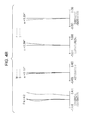
- FIG. 7 is a cross-sectional view of a zoom lens system focused to infinity at a wide angle end, according to a fourth embodiment.
- FIGS. 8A and 8B are aberration diagrams of the zoom lens system at a wide angle end and at a telescopic end focused at an object distance of 15 m, according to the fourth embodiment.
- FIG. 9 is a cross-sectional view of a zoom lens system focused to infinity at a wide angle end, according to a fifth embodiment.
- FIGS. 10A and 10B are aberration diagrams of the zoom lens system at a wide angle end and at a telescopic end focused at an object distance of 15 m, according to the fifth embodiment.
- FIG. 11 is a schematic diagram of an image capturing apparatus including a zoom lens system of the present disclosure.
- a positive lead type zoom lens system in order to obtain a high optical performance throughout the entire zoom and focus range while maintaining a wide view angle and a high magnification, it is important to set the configuration of the first lens unit, the refractive power, and the focus method in an appropriate manner. Without the above configuration being appropriately set, it is difficult to obtain a zoom lens system having a high optical performance with a wide view angle and a high zoom ratio throughout the entire zoom and focus range.
- the present disclosure provides a zoom lens system with a wide view angle and a high zoom ratio throughout the entire zoom and focus range while achieving a favorable zooming operation, and an image capturing apparatus including the zoom lens system.
- a zoom lens system of the present disclosure includes, in order from the object side to the image side, a first lens unit having a positive refractive power that does not move for zooming, a second lens unit having a negative refractive power that moves during zooming, and a third lens unit having a positive refractive power that moves during zooming.
- the lens unit not moving to zoom means that the lens unit is not moved for the purpose of zooming alone, but when zooming and focusing are performed at the same time, a given lens unit may be moved for focusing.
- FIG. 1 is a cross-sectional view of lenses of a first exemplary embodiment (a first numerical embodiment) of the present disclosure focused to infinity at a wide angle end.
- FIGS. 2A and 2B are aberration diagrams when the lenses at a wide angle end and at a telescopic end, respectively, are focused to a distance of 15 m. Note that the values of the object distances are distances in which the numerical embodiments described later are expressed in millimeters (mm). The object distance is a distance from the first lens surface to the plane (physical location) where the object is located during an imaging operation. The same applies hereinafter to all embodiments.
- FIG. 3 is a cross-sectional view of lenses of a second exemplary embodiment (a second numerical embodiment) of the present disclosure focused to infinity at a wide angle end.
- FIGS. 4A and 4B are aberration diagrams when the lenses at a wide angle end and at a telescopic end, respectively, are focused to a distance of 15 m.
- FIG. 5 is a cross-sectional view of lenses of a third exemplary embodiment (a third numerical embodiment) of the present disclosure focused to infinity at a wide angle end.
- FIGS. 6A and 6B are aberration diagrams when the lenses at a wide angle end and at a telescopic end, respectively, are focused to a distance of 15 m.
- FIG. 7 is a cross-sectional view of lenses of a fourth exemplary embodiment (a fourth numerical embodiment) of the present disclosure focused to infinity at a wide angle end.
- FIGS. 8A and 8B are aberration diagrams when the lenses at a wide angle end and at a telescopic end, respectively, are focused to a distance of 15 m.
- FIG. 9 is a cross-sectional view of lenses of a fifth exemplary embodiment (a fifth numerical embodiment) of the present disclosure focused to infinity at a wide angle end.
- FIGS. 10A and 10B are aberration diagrams when the lenses at a wide angle end and at a telescopic end, respectively, are focused to a distance of 15 m.
- reference numeral U 1 is the first lens unit having a positive refractive power that does not move for zooming.
- Reference numeral U 1 b is a focus lens unit in the first lens unit U 1 and moves to the object side when performing focus adjustment from an infinite object to a near object.
- Reference numeral U 1 a is a stationary lens unit in the first lens unit U 1 and does not move for focusing.
- Reference numeral U 1 a denotes a first a-lens unit and reference numeral U 1 b denotes a b-lens unit in the first lens unit U 1 .
- Reference numeral U 2 is the second lens unit having a negative refractive power that moves during zooming.
- Reference numeral U 3 is the third lens unit having a positive refractive power that moves during zooming.
- reference numeral U 4 is the fourth lens unit having a positive refractive power that moves during zooming.
- Reference numeral U 5 is a fifth lens unit (a relay lens unit) for image forming that does not move for zooming.
- Reference label BK a glass block equivalent to an optical filter or the like.
- reference numeral U 4 is a fourth lens unit (a relay lens unit) for image forming that does not move for zooming.
- the zoom lens system of each exemplary embodiment performs zooming and correction of the image plane variation associated with zooming by changing each of the lens distances while moving on the optical axis.
- Reference numeral IP is an image plane or image surface and corresponds to an image pickup surface of a solid-state image pick up element (photoelectric conversion element), such as a CCD sensor or a CMOS sensor.
- the solid line represents an e-line and the two-dot chain line represents a g-line.
- the dotted line represents a meridional image surface of an e-line, and the solid line represents a sagittal image surface of the e-line.
- the two-dot chain line represents chromatic aberration of magnification at a g-line.
- Fno represents an F-number
- ⁇ represents a half angle of view (degree).
- the spherical aberration is drawn in a scale of 0.2 mm, the astigmatism in 0.2 mm, the curvature in 5%, and the magnification chromatic aberration in 0.05 mm.
- the zoom lens system of the present disclosure specifies conditions for obtaining a high optical performance with a high zoom ratio and a wide view angle throughout the entire zoom and focus range by specifying the focusing system of the first lens and the lens configuration of the first lens unit.
- the zoom lens system includes, in order from the object side to the image side, the first lens unit having a positive refractive power that does not move for zooming, the second lens unit having a negative refractive power that moves during zooming, and the third lens unit having a positive refractive power that moves during zooming. Furthermore, the distance between adjacent lens units change during zooming, and the first lens unit includes the first a-lens unit that does not move for focusing and the first b-lens unit that moves to the object side from the image side during focusing from an infinite object to a near object. Furthermore, the first a-lens unit is formed of two positive lenses and two negative lenses.
- the first lens unit includes two lens units, namely, the first a-lens unit on the object side and a first b-lens unit on the image side.
- the first a-lens unit on the object side does not move for focusing and the first b-lens unit on the image side moves during focusing.
- focus adjustment is made by moving from the image side to the object side.
- the height of the axial ray and that of the off axial ray changes and, accordingly, aberration variation occurs.
- the aberration variation increases towards the telephoto side.
- the aberration variation can be classified into chromatic aberration and aberration attributed to a standard wavelength.
- the first a-lens unit having two negative lenses and two positive lenses increases the number of lens surfaces in the first a-lens unit and can suppress the amount of aberration occurring on the surfaces in the first a-lens unit. Furthermore, plural combinations of adjoining surfaces (a convexity and a concavity, in the first exemplary embodiment, the second surface and the third surface, and the sixth surface and the seventh surface) that have close curvatures and in which the aberrations are cancelled out with respect to each other can be provided. Since the combinations can correct high order aberrations, by providing plural combinations, the aberrations occurring in the first a-lens unit from a low order aberration to a high order aberration can be corrected in a favorable manner.
- dispersion (Abbe number ⁇ d) of the positive lens and the negative lens can be brought close to each other. Accordingly, related to the selection of the glass materials, the dispersion characteristics (partial dispersion ratios ⁇ gf) of the positive lens and the negative lens can be brought close to each other and the chromatic aberration of the first a-lens unit can be corrected in a favorable manner throughout the entire wavelength.
- a condition for obtaining a zoom lens system having a high zoom ratio and a wide view angle is specified by specifying the configuration of the lenses and the refractive powers of the lens units of the fourth lens unit and after.
- Another feature of the zoom lens system of the present disclosure is that the ratio of the focal length of the negative lens of the first a-lens unit and the ratio of dispersion of the lens material thereof are specified. With the above, chromatic aberration and various aberrations of the first a-lens unit can be suppressed from occurring and aberration occurring due to focusing can be favorably corrected.
- the Abbe number is expressed by the following equation when the refractive indexes at the F-line (486.1 nm), the d-line (587.6 nm), and the C-line (656.3 nm) of the Fraunhofer lines are Nd, NF, and NC, respectively.
- ⁇ d ( Nd ⁇ 1)/( NF ⁇ NC )
- the refractive power of the negative lens disposed on the object side that has a large off axial ray height becomes strong, and the distortion on the wide-angle side and the curvature of the image surface worsen. Furthermore, the sensitivities in the spherical aberration and the like of the first a-lens unit increase.
- the refractive power of the negative lens disposed on the object side becomes weak, and the retrofocusing of the first lens unit will become difficult and reduction in size will become difficult. Furthermore, the refractive power of the negative lens disposed on the image side becomes strong and the spherical aberration and the like of the first a-lens unit increase.
- the dispersion of the negative lens disposed on the object side that has a large off axial ray height becomes strong and the negative lens disposed on the image side that has a small off axial ray height becomes weak, making it difficult to achieve both corrections of the axial chromatic aberration and the magnification chromatic aberration.
- the dispersion of the negative lens disposed on the object side that has a large off axial ray height becomes weak and the negative lens disposed on the image side that has a small off axial ray height becomes strong, making it difficult to achieve corrections of both the axial chromatic aberration and the magnification chromatic aberration.
- conditional expressions (1) and (2) in the following manner. 0.40 ⁇ fn 1/ fn 2 ⁇ 1.90 (1a) 0.35 ⁇ n 1/ ⁇ n 2 ⁇ 2.50 (2a)
- the condition for suppressing various aberrations of the first a-lens unit from occurring and for favorably correcting the aberration occurring due to focusing is specified by specifying the ratio between the focal length of the negative lens of the first a-lens unit and the focal length of the first lens unit.
- the refractive power of the negative lens disposed on the object side that has a high off axial ray becomes strong, and the distortion on the wide-angle side and the curvature of the image surface worsen. Furthermore, the sensitivities in the spherical aberration and the like of the first a-lens unit increase.
- the refractive power of the negative lens disposed on the object side becomes weak, and it will be difficult to perform retrofocusing of the first lens unit and to achieve reduction in size.
- the refractive power of the negative lens disposed on the image side becomes strong and the spherical aberration and the like of the first a-lens unit increase.
- the refractive power of the negative lens disposed on the object side becomes weak, making it difficult to favorably correct the chromatic aberration and various aberrations of the first a-lens unit; accordingly, the occurrence of aberration due to focusing increases.
- the zoom lens system of the present disclosure specifies the condition of the dispersion characteristic of the lens material of the first a-lens unit to specify the condition for favorably correcting the variation in the axial chromatic aberration due to focusing, the axial chromatic aberration due to zooming, and the variation in the magnification chromatic aberration.
- the chromatic aberration correction effect of the first a-lens unit becomes insufficient making it difficult to favorably correct the variation in the axial chromatic aberration due to focusing, the axial chromatic aberration due to zooming, and the variation in the magnification chromatic aberration.
- the dispersions of the positive lens and the negative lens of the first a-lens unit become close to each other and the refractive power of each of the lenses of the first a-lens unit increases. As a result, it is difficult to perform a favorable correction of coma aberration variation due to focusing.
- conditional expression (5) it is desirable to set the conditional expression (5) in the following manner. ⁇ 0.50000 ⁇ 10 ⁇ 3 ⁇ ( ⁇ pa ⁇ nx )/( ⁇ pa ⁇ nx ) ⁇ 0.100000 ⁇ 10 ⁇ 3 (5a)
- the condition for achieving a favorable correction of the aberration throughout the entire zooming range while having high magnification is specified by specifying the focal lengths of the first lens unit and the second lens unit.
- the focal length of the second lens unit is f2
- the following conditional expression holds true. 6.00 ⁇
- An another feature of the zoom lens system of the present disclosure is that the ratio between the combined focal length of the negative lenses of the first a-lens unit, the combined focal length of the positive lenses of the first a-lens unit, and the focal length of the first lens unit are specified.
- combined focal length fx of the plurality of lenses is expressed in the following manner when each of the focal length of the plurality of lenses is
- 1/fx 1/f1+1/f2+1/f3+ . . . .
- the refractive power of each of the lenses of the first a-lens unit becomes strong and it is difficult to correct the spherical aberration and the coma aberration at the telescopic end. Furthermore, the sensitivities in the spherical aberration and the like of the first a-lens unit increase.
- achromatization of the first a-lens unit becomes insufficient; accordingly, variation in chromatic aberration due to focusing increases.
- the refractive power of the negative lens becomes strong, and the distortion on the wide-angle side and the curvature of the image surface worsen. Furthermore, the sensitivities in the spherical aberration and the like of the first a-lens unit increase.
- achromatization of the first a-lens unit becomes insufficient; accordingly, variation in chromatic aberration due to focusing increases.
- the refractive power of the positive lens becomes strong and it is difficult to correct the spherical aberration and the coma aberration at the telescopic end. Furthermore, the sensitivities in the spherical aberration and the like of the first a-lens unit increase. When exceeding the upper limit of the conditional expression (9), achromatization of the first a-lens unit becomes insufficient; accordingly, variation in chromatic aberration due to focusing increases.
- conditional expressions (7), (8), and (9) in the following manner. 0.85 ⁇
- reference numeral U 1 is a first lens unit having a positive refractive power that does not move for zooming.
- the first lens unit U 1 includes, in the order from the object side to the image side, a first a-lens unit U 1 a that does not move for focusing, and a first b-lens unit U 1 b that moves during focusing.
- the first b-lens unit U 1 b for focusing moves towards the object side as the object distance changes from long distance to short distance.
- Reference numeral U 2 and U 3 are a second lens unit having a negative refractive power and a third lens unit (a variator lens unit) having a positive refractive power, respectively, that move during zooming.
- the second lens unit U 2 and the third lens unit U 3 perform magnification from a wide angle end to a telescopic end by moving on the optical axis.
- Reference numeral U 4 is a fourth lens unit (a compensator lens unit) having a positive refractive power that moves during zooming.
- the fourth lens unit U 4 moves on the optical axis while interlocking with the movement of the second and third lens units U 2 and U 3 and corrects the image plane variation associated with the magnification.
- Reference numeral SP is an aperture diaphragm.
- Reference numeral U 5 is a fifth lens unit (a relay lens unit R) having a positive refractive power that does not move during zooming.
- the aperture diaphragm SP is disposed between the fourth lens unit U 4 and the fifth lens unit U 5
- the present exemplary embodiment satisfies each of the conditional expressions (1) to (9); accordingly, a zoom lens system with a high zoom ratio and a high performance, and, moreover, with little degradation in performance caused by manufacturing error can be obtained.
- a zoom lens system of a second exemplary embodiment in FIG. 3 has a zoom type, such as the number of lens unit, the refractive power of each lens unit, and the condition in which each lens unit move while focusing, that is similar to that of the first exemplary embodiment.
- the present exemplary embodiment satisfies each of the conditional expressions; accordingly, the advantageous effects that are the same as those of the first exemplary embodiment are obtained.
- reference numeral U 1 is a first lens unit having a positive refractive power that does not move for zooming.
- the first lens unit U 1 includes, in the order from the object side to the image side, a first a-lens unit U 1 a that does not move for focusing, and a first b-lens unit U 1 b that moves during focusing.
- the first b-lens unit U 1 b for focusing moves towards the object side as the object distance changes from long distance to short distance.
- Reference numeral U 2 is a second lens unit (a compensator lens unit) having a positive refractive power that moves during zooming.
- the second lens unit U 2 performs magnification from a wide angle end to a telescopic end by moving on the optical axis.
- Reference numeral U 3 is a third lens unit (a compensator lens unit) having a positive refractive power that moves during zooming.
- the third lens unit U 3 moves on the optical axis while interlocking with the movement of the second lens unit U 2 and corrects the image plane variation associated with the magnification.
- Reference numeral SP is an aperture diaphragm.
- Reference numeral U 4 is a fourth lens unit (a relay lens unit R) having a positive refractive power that is stationary during zooming.
- the aperture diaphragm SP is disposed between the third lens unit U 3 and the fourth lens unit U 4 .
- the present exemplary embodiment satisfies each of the conditional expressions (1) to (9); accordingly, a zoom lens system with a high zoom ratio and a high performance, and, moreover, with little degradation in performance caused by manufacturing error can be obtained.
- a zoom lens system of a fourth exemplary embodiment in FIG. 7 has a zoom type, such as the number of lens unit, the refractive power of each lens unit, and the condition in which each lens unit move while focusing, that is similar to that of the first exemplary embodiment.
- the present exemplary embodiment satisfies each of the conditional expressions; accordingly, the advantageous effects that are the same as those of the first exemplary embodiment are obtained.
- a zoom lens system of a fifth exemplary embodiment in FIG. 9 has a zoom type, such as the number of lens unit, the refractive power of each lens unit, and the condition in which each lens unit move while focusing, that is the same as that of the first exemplary embodiment.
- the present exemplary embodiment satisfies each of the conditional expressions; accordingly, the advantageous effects that are the same as those of the first exemplary embodiment are obtained.
- first a-lens unit U 1 a which does not move for focusing, of the first lens unit U 1 of each exemplary embodiment may have an aspherical surface.
- the first b-lens unit U 1 b of each exemplary embodiment may integrally move as a whole to the object side or may move in a composite manner as two separate members.
- FIG. 11 is a schematic diagram illustrating an essential portion of the image capturing apparatus of the present disclosure.
- reference numeral 101 is the zoom lens system of either one of the first to fifth numerical embodiments.
- Reference numeral 124 is a camera.
- the zoom lens system 101 is detachable with respect to the camera 124 .
- Reference numeral 125 is the image capturing apparatus configured by mounting the zoom lens system 101 on the camera 124 .
- the zoom lens system 101 includes a first lens unit F, a magnification lens unit LZ, and a rear lens unit R.
- the first lens unit F includes a lens unit for focus adjustment.
- the magnification lens unit LZ includes a unit that moves on the optical axis during zooming and a unit that moves on the optical axis for correcting the image plane variation associated with zooming.
- the rear lens R includes an aperture diaphragm SP and a lens unit for image forming.
- Reference numerals 114 and 115 are drive mechanisms, such as a helicoid or a cam structures, that drive the first lens unit F and the magnification lens unit LZ in the optical axis direction.
- Reference numerals 116 , 117 to 118 are motors (driving devices) that electrically drive the drive mechanisms 114 and 115 and the aperture diaphragm SP.
- Reference numerals 119 , 120 to 121 are detectors, such as an encoder, a potentiometer, or a photosensor, for detecting the positions of the first lens unit F and the magnification lens unit LZ on the optical axis and the aperture diameter of the aperture diaphragm SP.
- reference numeral 109 is a glass block equivalent to an optical filter or a color split prism inside the camera 124
- reference numeral 110 is a solid-state image pick up element (a photoelectric conversion element) such as a CCD sensor or a CMOS sensor that photo receives the subject image formed by the zoom lens system 101
- reference numerals 111 and 122 are CPUs that control the various drive of the camera 124 and a zoom lens system body 101 .
- surface number i represents the number of the surface from the object side
- ri represents the curvature radius of the i th surface from the object side
- di represents the distance between the i th and the i+1 th surfaces from the object side
- ndi and ⁇ di represent the refractive index and the Abbe number of the i th optical member.
- BF represents a back focus.
- a notation in the form “e-Z” denotes an exponential notation in the form “ ⁇ 10 ⁇ Z ”, and a surface number marked with an asterisk “*” represents an aspherical surface.
- Table 1 The correspondence between each exemplary embodiment and the conditional expressions described above is illustrated in Table 1.
Landscapes
- Physics & Mathematics (AREA)
- General Physics & Mathematics (AREA)
- Optics & Photonics (AREA)
- Chemical & Material Sciences (AREA)
- Dispersion Chemistry (AREA)
- Lenses (AREA)
- Nonlinear Science (AREA)
Applications Claiming Priority (2)
| Application Number | Priority Date | Filing Date | Title |
|---|---|---|---|
| JP2015081063A JP6544975B2 (ja) | 2015-04-10 | 2015-04-10 | ズームレンズおよび撮像装置 |
| JP2015-081063 | 2015-04-10 |
Publications (2)
| Publication Number | Publication Date |
|---|---|
| US20160299323A1 US20160299323A1 (en) | 2016-10-13 |
| US9804370B2 true US9804370B2 (en) | 2017-10-31 |
Family
ID=57111736
Family Applications (1)
| Application Number | Title | Priority Date | Filing Date |
|---|---|---|---|
| US15/091,463 Active US9804370B2 (en) | 2015-04-10 | 2016-04-05 | Zoom lens system |
Country Status (2)
| Country | Link |
|---|---|
| US (1) | US9804370B2 (ja) |
| JP (1) | JP6544975B2 (ja) |
Families Citing this family (2)
| Publication number | Priority date | Publication date | Assignee | Title |
|---|---|---|---|---|
| JP6631085B2 (ja) * | 2015-08-19 | 2020-01-15 | 株式会社シグマ | ズームレンズ |
| JP6649287B2 (ja) * | 2017-01-05 | 2020-02-19 | 富士フイルム株式会社 | ズームレンズおよび撮像装置 |
Citations (4)
| Publication number | Priority date | Publication date | Assignee | Title |
|---|---|---|---|---|
| US6002528A (en) * | 1997-04-01 | 1999-12-14 | Canon Kabushiki Kaisha | Zoom lens |
| JP2001183584A (ja) | 1999-10-14 | 2001-07-06 | Canon Inc | ズームレンズ及び撮影装置 |
| US20130271630A1 (en) * | 2012-04-13 | 2013-10-17 | Canon Kabushiki Kaisha | Zoom lens and image pickup apparatus including the same |
| US20150362711A1 (en) * | 2014-06-13 | 2015-12-17 | Canon Kabushiki Kaisha | Zoom lens and image pickup apparatus including the same |
Family Cites Families (6)
| Publication number | Priority date | Publication date | Assignee | Title |
|---|---|---|---|---|
| JPS63188110A (ja) * | 1987-01-30 | 1988-08-03 | Asahi Optical Co Ltd | 望遠ズ−ムレンズ |
| JP2004029640A (ja) * | 2002-06-28 | 2004-01-29 | Canon Inc | 防振ズームレンズ装置およびカメラシステム |
| JP4203284B2 (ja) * | 2002-08-27 | 2008-12-24 | 株式会社シグマ | 望遠ズームレンズ |
| KR20090126817A (ko) * | 2008-06-05 | 2009-12-09 | 삼성디지털이미징 주식회사 | 망원 줌 렌즈 |
| JP5517547B2 (ja) * | 2009-10-05 | 2014-06-11 | キヤノン株式会社 | ズームレンズ及びそれを有する撮像装置 |
| JP5438620B2 (ja) * | 2010-07-29 | 2014-03-12 | 富士フイルム株式会社 | ズームレンズおよび撮像装置 |
-
2015
- 2015-04-10 JP JP2015081063A patent/JP6544975B2/ja active Active
-
2016
- 2016-04-05 US US15/091,463 patent/US9804370B2/en active Active
Patent Citations (4)
| Publication number | Priority date | Publication date | Assignee | Title |
|---|---|---|---|---|
| US6002528A (en) * | 1997-04-01 | 1999-12-14 | Canon Kabushiki Kaisha | Zoom lens |
| JP2001183584A (ja) | 1999-10-14 | 2001-07-06 | Canon Inc | ズームレンズ及び撮影装置 |
| US20130271630A1 (en) * | 2012-04-13 | 2013-10-17 | Canon Kabushiki Kaisha | Zoom lens and image pickup apparatus including the same |
| US20150362711A1 (en) * | 2014-06-13 | 2015-12-17 | Canon Kabushiki Kaisha | Zoom lens and image pickup apparatus including the same |
Also Published As
| Publication number | Publication date |
|---|---|
| JP2016200729A (ja) | 2016-12-01 |
| US20160299323A1 (en) | 2016-10-13 |
| JP6544975B2 (ja) | 2019-07-17 |
Similar Documents
| Publication | Publication Date | Title |
|---|---|---|
| US9268120B2 (en) | Zoom lens and image pickup apparatus including the same | |
| US8456746B2 (en) | Zoom lens and image pickup apparatus including the same | |
| US10838200B2 (en) | Optical system and image pickup apparatus including the same | |
| US9400374B2 (en) | Zoom lens and image pickup apparatus including the same | |
| US9588323B2 (en) | Zoom lens and image pickup apparatus having the same | |
| US9350919B2 (en) | Image pickup apparatus | |
| US8743469B2 (en) | Zoom lens and image pickup apparatus including the same | |
| US20170276917A1 (en) | Zoom lens and image pickup apparatus including the same | |
| US8934047B2 (en) | Zoom lens and image pickup apparatus including the same | |
| US11073684B2 (en) | Zoom lens and image pickup apparatus including the same | |
| US9798119B2 (en) | Zoom lens and image pickup apparatus | |
| US20120087016A1 (en) | Zoom lens and image pickup apparatus with zoom lens | |
| US10228534B2 (en) | Optical system and image pickup apparatus including the same | |
| US11022783B2 (en) | Zoom lens and image pickup apparatus | |
| US10120171B2 (en) | Zoom lens and image pickup apparatus having the same | |
| US9678317B2 (en) | Zoom lens and image pickup apparatus including the same | |
| JP6545002B2 (ja) | ズームレンズ及びそれを有する撮像装置 | |
| US20150316756A1 (en) | Zoom lens and image pickup apparatus including the same | |
| US11002944B2 (en) | Optical system and image pickup apparatus | |
| US9648244B2 (en) | Zoom lens and image pickup apparatus including the same | |
| US11327281B2 (en) | Zoom lens and image pickup apparatus including the same | |
| US20200379222A1 (en) | Zoom lens and image pickup apparatus | |
| US20150177499A1 (en) | Zoom lens and image pickup apparatus using the same | |
| US8593736B2 (en) | Zoom lens and image pickup apparatus including the same | |
| US9804370B2 (en) | Zoom lens system |
Legal Events
| Date | Code | Title | Description |
|---|---|---|---|
| AS | Assignment |
Owner name: CANON KABUSHIKI KAISHA, JAPAN Free format text: ASSIGNMENT OF ASSIGNORS INTEREST;ASSIGNOR:SAKAMOTO, MASARU;REEL/FRAME:039022/0736 Effective date: 20160324 |
|
| STCF | Information on status: patent grant |
Free format text: PATENTED CASE |
|
| MAFP | Maintenance fee payment |
Free format text: PAYMENT OF MAINTENANCE FEE, 4TH YEAR, LARGE ENTITY (ORIGINAL EVENT CODE: M1551); ENTITY STATUS OF PATENT OWNER: LARGE ENTITY Year of fee payment: 4 |