US9797366B2 - Pumped-storage power plant - Google Patents
Pumped-storage power plant Download PDFInfo
- Publication number
- US9797366B2 US9797366B2 US14/357,328 US201214357328A US9797366B2 US 9797366 B2 US9797366 B2 US 9797366B2 US 201214357328 A US201214357328 A US 201214357328A US 9797366 B2 US9797366 B2 US 9797366B2
- Authority
- US
- United States
- Prior art keywords
- water
- base body
- power plant
- pressure
- pressure vessels
- Prior art date
- Legal status (The legal status is an assumption and is not a legal conclusion. Google has not performed a legal analysis and makes no representation as to the accuracy of the status listed.)
- Active
Links
- 238000003860 storage Methods 0.000 title claims abstract description 145
- XLYOFNOQVPJJNP-UHFFFAOYSA-N water Substances O XLYOFNOQVPJJNP-UHFFFAOYSA-N 0.000 claims abstract description 211
- 238000005381 potential energy Methods 0.000 claims abstract description 21
- 230000002706 hydrostatic effect Effects 0.000 claims abstract description 18
- 238000000034 method Methods 0.000 claims description 12
- 238000012423 maintenance Methods 0.000 claims description 10
- 239000013590 bulk material Substances 0.000 claims description 9
- 239000000463 material Substances 0.000 claims description 9
- 238000005086 pumping Methods 0.000 claims description 9
- 239000000945 filler Substances 0.000 claims description 8
- 238000007667 floating Methods 0.000 claims description 8
- 238000004519 manufacturing process Methods 0.000 claims description 6
- 230000002441 reversible effect Effects 0.000 claims description 6
- 238000009434 installation Methods 0.000 claims description 5
- 230000002787 reinforcement Effects 0.000 claims 1
- 230000008878 coupling Effects 0.000 description 14
- 238000010168 coupling process Methods 0.000 description 14
- 238000005859 coupling reaction Methods 0.000 description 14
- 238000010276 construction Methods 0.000 description 9
- 238000004146 energy storage Methods 0.000 description 9
- 238000013461 design Methods 0.000 description 8
- 238000010248 power generation Methods 0.000 description 6
- 239000004567 concrete Substances 0.000 description 5
- 239000011210 fiber-reinforced concrete Substances 0.000 description 5
- 230000008569 process Effects 0.000 description 5
- 238000004873 anchoring Methods 0.000 description 4
- 230000005611 electricity Effects 0.000 description 4
- 238000011084 recovery Methods 0.000 description 4
- 238000007789 sealing Methods 0.000 description 4
- 229910000831 Steel Inorganic materials 0.000 description 3
- 230000008901 benefit Effects 0.000 description 3
- 238000009826 distribution Methods 0.000 description 3
- 230000005484 gravity Effects 0.000 description 3
- 239000013535 sea water Substances 0.000 description 3
- 239000010959 steel Substances 0.000 description 3
- 238000004364 calculation method Methods 0.000 description 2
- 238000004140 cleaning Methods 0.000 description 2
- 150000001875 compounds Chemical class 0.000 description 2
- 230000001419 dependent effect Effects 0.000 description 2
- 238000006073 displacement reaction Methods 0.000 description 2
- 239000011796 hollow space material Substances 0.000 description 2
- 238000005065 mining Methods 0.000 description 2
- 238000003825 pressing Methods 0.000 description 2
- 230000009467 reduction Effects 0.000 description 2
- 239000011150 reinforced concrete Substances 0.000 description 2
- 239000004576 sand Substances 0.000 description 2
- 238000013459 approach Methods 0.000 description 1
- 230000005540 biological transmission Effects 0.000 description 1
- 238000009750 centrifugal casting Methods 0.000 description 1
- 238000011161 development Methods 0.000 description 1
- 230000018109 developmental process Effects 0.000 description 1
- 230000009977 dual effect Effects 0.000 description 1
- 230000000694 effects Effects 0.000 description 1
- 238000010616 electrical installation Methods 0.000 description 1
- 238000005868 electrolysis reaction Methods 0.000 description 1
- 238000009415 formwork Methods 0.000 description 1
- 239000003673 groundwater Substances 0.000 description 1
- 238000003306 harvesting Methods 0.000 description 1
- 230000010354 integration Effects 0.000 description 1
- 230000001788 irregular Effects 0.000 description 1
- 238000011031 large-scale manufacturing process Methods 0.000 description 1
- 239000000203 mixture Substances 0.000 description 1
- 238000012544 monitoring process Methods 0.000 description 1
- 230000006855 networking Effects 0.000 description 1
- 230000005855 radiation Effects 0.000 description 1
- 230000008439 repair process Effects 0.000 description 1
- 230000003068 static effect Effects 0.000 description 1
- 238000012916 structural analysis Methods 0.000 description 1
- 239000000126 substance Substances 0.000 description 1
- 238000009423 ventilation Methods 0.000 description 1
Images


Classifications
-
- F—MECHANICAL ENGINEERING; LIGHTING; HEATING; WEAPONS; BLASTING
- F03—MACHINES OR ENGINES FOR LIQUIDS; WIND, SPRING, OR WEIGHT MOTORS; PRODUCING MECHANICAL POWER OR A REACTIVE PROPULSIVE THRUST, NOT OTHERWISE PROVIDED FOR
- F03B—MACHINES OR ENGINES FOR LIQUIDS
- F03B13/00—Adaptations of machines or engines for special use; Combinations of machines or engines with driving or driven apparatus; Power stations or aggregates
- F03B13/10—Submerged units incorporating electric generators or motors
-
- F—MECHANICAL ENGINEERING; LIGHTING; HEATING; WEAPONS; BLASTING
- F03—MACHINES OR ENGINES FOR LIQUIDS; WIND, SPRING, OR WEIGHT MOTORS; PRODUCING MECHANICAL POWER OR A REACTIVE PROPULSIVE THRUST, NOT OTHERWISE PROVIDED FOR
- F03B—MACHINES OR ENGINES FOR LIQUIDS
- F03B13/00—Adaptations of machines or engines for special use; Combinations of machines or engines with driving or driven apparatus; Power stations or aggregates
- F03B13/06—Stations or aggregates of water-storage type, e.g. comprising a turbine and a pump
-
- F—MECHANICAL ENGINEERING; LIGHTING; HEATING; WEAPONS; BLASTING
- F03—MACHINES OR ENGINES FOR LIQUIDS; WIND, SPRING, OR WEIGHT MOTORS; PRODUCING MECHANICAL POWER OR A REACTIVE PROPULSIVE THRUST, NOT OTHERWISE PROVIDED FOR
- F03B—MACHINES OR ENGINES FOR LIQUIDS
- F03B3/00—Machines or engines of reaction type; Parts or details peculiar thereto
- F03B3/10—Machines or engines of reaction type; Parts or details peculiar thereto characterised by having means for functioning alternatively as pumps or turbines
-
- F—MECHANICAL ENGINEERING; LIGHTING; HEATING; WEAPONS; BLASTING
- F03—MACHINES OR ENGINES FOR LIQUIDS; WIND, SPRING, OR WEIGHT MOTORS; PRODUCING MECHANICAL POWER OR A REACTIVE PROPULSIVE THRUST, NOT OTHERWISE PROVIDED FOR
- F03D—WIND MOTORS
- F03D9/00—Adaptations of wind motors for special use; Combinations of wind motors with apparatus driven thereby; Wind motors specially adapted for installation in particular locations
- F03D9/10—Combinations of wind motors with apparatus storing energy
- F03D9/13—Combinations of wind motors with apparatus storing energy storing gravitational potential energy
- F03D9/14—Combinations of wind motors with apparatus storing energy storing gravitational potential energy using liquids
-
- F—MECHANICAL ENGINEERING; LIGHTING; HEATING; WEAPONS; BLASTING
- F03—MACHINES OR ENGINES FOR LIQUIDS; WIND, SPRING, OR WEIGHT MOTORS; PRODUCING MECHANICAL POWER OR A REACTIVE PROPULSIVE THRUST, NOT OTHERWISE PROVIDED FOR
- F03D—WIND MOTORS
- F03D9/00—Adaptations of wind motors for special use; Combinations of wind motors with apparatus driven thereby; Wind motors specially adapted for installation in particular locations
- F03D9/20—Wind motors characterised by the driven apparatus
- F03D9/25—Wind motors characterised by the driven apparatus the apparatus being an electrical generator
-
- F—MECHANICAL ENGINEERING; LIGHTING; HEATING; WEAPONS; BLASTING
- F03—MACHINES OR ENGINES FOR LIQUIDS; WIND, SPRING, OR WEIGHT MOTORS; PRODUCING MECHANICAL POWER OR A REACTIVE PROPULSIVE THRUST, NOT OTHERWISE PROVIDED FOR
- F03D—WIND MOTORS
- F03D9/00—Adaptations of wind motors for special use; Combinations of wind motors with apparatus driven thereby; Wind motors specially adapted for installation in particular locations
- F03D9/007—Adaptations of wind motors for special use; Combinations of wind motors with apparatus driven thereby; Wind motors specially adapted for installation in particular locations the wind motor being combined with means for converting solar radiation into useful energy
-
- H—ELECTRICITY
- H02—GENERATION; CONVERSION OR DISTRIBUTION OF ELECTRIC POWER
- H02S—GENERATION OF ELECTRIC POWER BY CONVERSION OF INFRARED RADIATION, VISIBLE LIGHT OR ULTRAVIOLET LIGHT, e.g. USING PHOTOVOLTAIC [PV] MODULES
- H02S10/00—PV power plants; Combinations of PV energy systems with other systems for the generation of electric power
- H02S10/10—PV power plants; Combinations of PV energy systems with other systems for the generation of electric power including a supplementary source of electric power, e.g. hybrid diesel-PV energy systems
- H02S10/12—Hybrid wind-PV energy systems
-
- Y—GENERAL TAGGING OF NEW TECHNOLOGICAL DEVELOPMENTS; GENERAL TAGGING OF CROSS-SECTIONAL TECHNOLOGIES SPANNING OVER SEVERAL SECTIONS OF THE IPC; TECHNICAL SUBJECTS COVERED BY FORMER USPC CROSS-REFERENCE ART COLLECTIONS [XRACs] AND DIGESTS
- Y02—TECHNOLOGIES OR APPLICATIONS FOR MITIGATION OR ADAPTATION AGAINST CLIMATE CHANGE
- Y02E—REDUCTION OF GREENHOUSE GAS [GHG] EMISSIONS, RELATED TO ENERGY GENERATION, TRANSMISSION OR DISTRIBUTION
- Y02E10/00—Energy generation through renewable energy sources
- Y02E10/20—Hydro energy
-
- Y02E10/22—
-
- Y02E10/223—
-
- Y—GENERAL TAGGING OF NEW TECHNOLOGICAL DEVELOPMENTS; GENERAL TAGGING OF CROSS-SECTIONAL TECHNOLOGIES SPANNING OVER SEVERAL SECTIONS OF THE IPC; TECHNICAL SUBJECTS COVERED BY FORMER USPC CROSS-REFERENCE ART COLLECTIONS [XRACs] AND DIGESTS
- Y02—TECHNOLOGIES OR APPLICATIONS FOR MITIGATION OR ADAPTATION AGAINST CLIMATE CHANGE
- Y02E—REDUCTION OF GREENHOUSE GAS [GHG] EMISSIONS, RELATED TO ENERGY GENERATION, TRANSMISSION OR DISTRIBUTION
- Y02E10/00—Energy generation through renewable energy sources
- Y02E10/30—Energy from the sea, e.g. using wave energy or salinity gradient
-
- Y02E10/32—
-
- Y—GENERAL TAGGING OF NEW TECHNOLOGICAL DEVELOPMENTS; GENERAL TAGGING OF CROSS-SECTIONAL TECHNOLOGIES SPANNING OVER SEVERAL SECTIONS OF THE IPC; TECHNICAL SUBJECTS COVERED BY FORMER USPC CROSS-REFERENCE ART COLLECTIONS [XRACs] AND DIGESTS
- Y02—TECHNOLOGIES OR APPLICATIONS FOR MITIGATION OR ADAPTATION AGAINST CLIMATE CHANGE
- Y02E—REDUCTION OF GREENHOUSE GAS [GHG] EMISSIONS, RELATED TO ENERGY GENERATION, TRANSMISSION OR DISTRIBUTION
- Y02E10/00—Energy generation through renewable energy sources
- Y02E10/50—Photovoltaic [PV] energy
-
- Y—GENERAL TAGGING OF NEW TECHNOLOGICAL DEVELOPMENTS; GENERAL TAGGING OF CROSS-SECTIONAL TECHNOLOGIES SPANNING OVER SEVERAL SECTIONS OF THE IPC; TECHNICAL SUBJECTS COVERED BY FORMER USPC CROSS-REFERENCE ART COLLECTIONS [XRACs] AND DIGESTS
- Y02—TECHNOLOGIES OR APPLICATIONS FOR MITIGATION OR ADAPTATION AGAINST CLIMATE CHANGE
- Y02E—REDUCTION OF GREENHOUSE GAS [GHG] EMISSIONS, RELATED TO ENERGY GENERATION, TRANSMISSION OR DISTRIBUTION
- Y02E10/00—Energy generation through renewable energy sources
- Y02E10/70—Wind energy
- Y02E10/72—Wind turbines with rotation axis in wind direction
-
- Y—GENERAL TAGGING OF NEW TECHNOLOGICAL DEVELOPMENTS; GENERAL TAGGING OF CROSS-SECTIONAL TECHNOLOGIES SPANNING OVER SEVERAL SECTIONS OF THE IPC; TECHNICAL SUBJECTS COVERED BY FORMER USPC CROSS-REFERENCE ART COLLECTIONS [XRACs] AND DIGESTS
- Y02—TECHNOLOGIES OR APPLICATIONS FOR MITIGATION OR ADAPTATION AGAINST CLIMATE CHANGE
- Y02E—REDUCTION OF GREENHOUSE GAS [GHG] EMISSIONS, RELATED TO ENERGY GENERATION, TRANSMISSION OR DISTRIBUTION
- Y02E60/00—Enabling technologies; Technologies with a potential or indirect contribution to GHG emissions mitigation
- Y02E60/16—Mechanical energy storage, e.g. flywheels or pressurised fluids
-
- Y02E60/17—
-
- Y—GENERAL TAGGING OF NEW TECHNOLOGICAL DEVELOPMENTS; GENERAL TAGGING OF CROSS-SECTIONAL TECHNOLOGIES SPANNING OVER SEVERAL SECTIONS OF THE IPC; TECHNICAL SUBJECTS COVERED BY FORMER USPC CROSS-REFERENCE ART COLLECTIONS [XRACs] AND DIGESTS
- Y02—TECHNOLOGIES OR APPLICATIONS FOR MITIGATION OR ADAPTATION AGAINST CLIMATE CHANGE
- Y02E—REDUCTION OF GREENHOUSE GAS [GHG] EMISSIONS, RELATED TO ENERGY GENERATION, TRANSMISSION OR DISTRIBUTION
- Y02E70/00—Other energy conversion or management systems reducing GHG emissions
- Y02E70/30—Systems combining energy storage with energy generation of non-fossil origin
-
- Y—GENERAL TAGGING OF NEW TECHNOLOGICAL DEVELOPMENTS; GENERAL TAGGING OF CROSS-SECTIONAL TECHNOLOGIES SPANNING OVER SEVERAL SECTIONS OF THE IPC; TECHNICAL SUBJECTS COVERED BY FORMER USPC CROSS-REFERENCE ART COLLECTIONS [XRACs] AND DIGESTS
- Y02—TECHNOLOGIES OR APPLICATIONS FOR MITIGATION OR ADAPTATION AGAINST CLIMATE CHANGE
- Y02P—CLIMATE CHANGE MITIGATION TECHNOLOGIES IN THE PRODUCTION OR PROCESSING OF GOODS
- Y02P70/00—Climate change mitigation technologies in the production process for final industrial or consumer products
- Y02P70/50—Manufacturing or production processes characterised by the final manufactured product
-
- Y—GENERAL TAGGING OF NEW TECHNOLOGICAL DEVELOPMENTS; GENERAL TAGGING OF CROSS-SECTIONAL TECHNOLOGIES SPANNING OVER SEVERAL SECTIONS OF THE IPC; TECHNICAL SUBJECTS COVERED BY FORMER USPC CROSS-REFERENCE ART COLLECTIONS [XRACs] AND DIGESTS
- Y02—TECHNOLOGIES OR APPLICATIONS FOR MITIGATION OR ADAPTATION AGAINST CLIMATE CHANGE
- Y02P—CLIMATE CHANGE MITIGATION TECHNOLOGIES IN THE PRODUCTION OR PROCESSING OF GOODS
- Y02P80/00—Climate change mitigation technologies for sector-wide applications
- Y02P80/10—Efficient use of energy, e.g. using compressed air or pressurized fluid as energy carrier
Definitions
- the present disclosure concerns a pumped storage power plant for temporary reversible storage of energy, such as energy from wind power stations and/or photovoltaic systems with fluctuating availability over time, and also concerns a power supply network having a pumped storage power plant, and a method for reversible temporary storage of electrical energy from primary power plants.
- Wind force and wind direction are subject to climatic and natural variations, however, and the wind frequently can cease, as well.
- An industrial society can only use wind power as a reliable energy source if it is continuously available, however.
- the power W is obtained from the product of the height difference h between the two storage basins and the water flow rate M.
- E (kW) 9.81 ⁇ M ⁇ h ⁇ t/3600 (hours), where t is the maximum time period in hours for lowering the water level in the upper storage basin.
- phases of pumping, storage, and power generation alternate continuously with one another.
- the pumped storage power plants can be started up in a minimum of time, and thus react quickly to power demand.
- German Patent Application 10 2011 013,329.1 discloses a pumped storage power plant with a pressure vessel to be sunk onto the ocean floor.
- WO 2011/112561 discloses an “Offshore Energy Harvesting, Storage and Power Generation System” with energy storage and power generation units that are anchored to the sea floor.
- An object of the present disclosure is to provide a novel pumped storage power plant that is almost arbitrarily scalable because of a modular construction and can provide an enormous storage capacity without burdening the existing landscape.
- the present disclosure utilizes the basic concept of using the ocean as the upper storage basin or water reservoir of a pumped storage power plant.
- Pressure vessels sunk onto the ocean floor serve as the lower storage basin or water reservoir.
- the lower water reservoir (the one with the lower potential energy) is an artificially created space, in particular, a hollow space formed by the pressure vessel.
- an underwater pumped storage power plant for temporary reversible storage of energy from other power plants, such as power plants producing fluctuating energy over time, for example wind power stations and/or photovoltaic systems, is provided.
- this pumped storage power plant also uses a first and a second water reservoir, wherein the water in the second water reservoir has a higher potential energy than in the first water reservoir.
- the first water reservoir with the lower potential energy is now composed of an accumulator system made of artificial pressure vessels that can be filled with water, which system is sunk to the sea floor at a great depth.
- the accumulator system in this concept is built to be pressure-resistant such that it is resistant to deformation from the hydrostatic water pressure when it is pumped empty.
- the second water reservoir with the higher potential energy is composed of the ocean itself, which surrounds the pressure vessel.
- the potential energy corresponding to the difference in height from the ocean surface which is to say the water depth T
- the water depth T is released. If the water is subsequently pumped back out of the accumulator system into the surrounding ocean against the hydrostatic pressure PT at the water depth T, it is necessary to use electrical energy corresponding to the water column pressing down on the accumulator system at the water depth T, and this energy can thus be stored; naturally, this is reduced by the power losses that are otherwise normal, as well.
- At least a water vapor pressure remains in the interior of the accumulator system.
- the water vapor pressure in the interior of the accumulator system is on the order of approximately 100 mbar or more than 100 mbar.
- the accumulator system of the underwater pumped storage power plant has at least two pressure vessels that can be filled with water and that together constitute a common accumulator volume.
- the pressure vessels can be capable of being coupled to one another or of being permanently connected to one another, for example, so that an accumulator system with a modular design is formed.
- easy-to-assemble modules are used as pressure vessels, such as cylindrical or tubular or polyhedral or cubical pressure vessels, for example, which ensure good volume utilization when several of these pressure vessels are set up next to one another.
- the pressure vessels preferably have no moving parts. This means that no mechanical or electrical power components that are used for power generation or power dissipation (pump, turbine) are installed in or on the pressure vessel.
- the pressure vessels of the accumulator system are connected to one another by a sump.
- the sump constitutes the deepest, or at least one of the deepest, points of the accumulator system so that the water always collects in the sump, for example, through the simple exploitation of gravity.
- the accumulator system In order to allow the water to flow out, the accumulator system has a water outlet located at the sump with a pump located directly at the water outlet.
- the water is pumped out of the accumulator system by the pump directly into the surrounding ocean against the hydrostatic pressure PT corresponding to the water depth, wherein the pump converts electrical energy into the potential energy corresponding to the displaced water column.
- the structural shape of the accumulator system can thus be designed such that the pump is located in the region of the sump, and the water column prevailing in the underwater pumped storage power plant plus the vapor pressure produces a water column intake pressure equivalent to approximately 15 meters water column at the pump.
- This intake pressure may be helpful, since in this way it is possible to use large-scale pumps that currently are commercially available.
- ventilation of the pressure vessel can be omitted.
- the underwater pumped storage power plant additionally has a water inlet with a generator arranged directly at the water inlet.
- a common generator is used for the at least two or all pressure vessels so that during power generation operation the common generator fills the at least two pressure vessels of which the accumulator system is comprised through the water inlet, preferably uniformly.
- the generator converts the potential energy of the previously displaced water column back into the corresponding electrical energy.
- the accumulator system additionally has valves at the inlet and outlet in order to close them when energy is not currently being stored or recovered. Accordingly, the water is pumped out and flows in only over the short distance into the accumulator system, which is closed except for the water inlet and water outlet.
- the accumulator system is submerged to a depth of, e.g., 2000 m below the ocean surface, this corresponds to a pumped storage power plant in which the second water reservoir is located 2000 m above the first water reservoir, which is already an extraordinarily great height difference for conventional pumped storage power plants.
- the first water reservoir is composed of the interior of the accumulator system in the form of pressure vessels, such as pressure vessels of modular design that can be coupled to one another, or pressure tanks.
- the pressure tanks thus form a closed water storage volume, namely the water storage volume or water reservoir with the lower potential energy as compared to the surrounding ocean.
- the accumulator volume can be constructed in a modular manner such that large numbers of pressure vessels of this type are sunk to the ocean floor and coupled to one another in order to achieve a sufficiently large water storage volume, and hence the desired energy storage capacity, without occupying usable landscape above ground.
- the vessels use the common pump(s) and common generator(s) so that the pressure vessels constitute a common accumulator volume, and several pumps and/or generators can be spared.
- such a network of underwater pumped storage power plants preferably comprises a large number of accumulator systems located on the ocean floor that are connected electrically to one another on the ocean floor by a network of electric lines. There is no need to network with water pipes between the accumulator systems that are each equipped with a separate pump and generator.
- an accumulator system may have one or more advantages. Firstly, a pumped storage power plant with such a modular construction can be provided that is matched in size to the application purpose and application site, and thus entails lower costs. Moreover, the choice and design of suitable pressure vessels is simplified, since pressure vessels that are optimal in terms of structure (the pressure vessel is a construction with considerable dead weight in the filled state) and design can be used and, moreover, the accumulator volume can be matched to the capacity of suitable pump and turbine units. Multiple pressure vessels can accordingly be connected together hydraulically to form an accumulator system, and filling and emptying take place at a single point. Naturally, the hydraulic connections must be constituted such that it is possible for the water to flow in and out unhindered.
- connection of the pressure vessels to the sump has at least one shutoff valve for disconnecting at least one of the pressure vessels from the accumulator system so that an individual pressure vessel can also be disconnected from the rest of the accumulator system for maintenance purposes or in the case of leaks.
- the modularity of the underwater pumped storage power plant can be further increased by the means that a pump-turbine unit is provided that accommodates, in particular, the water inlet, water outlet, common pump, and generator, as well as the electrical installation required for connection to the electric lines.
- the pump-turbine unit can be constructed such, that it is capable of being decoupled, from the other components, such as, e.g., the accumulator system of the underwater pumped storage power plant.
- the decoupleable pump-turbine unit can thus be brought to the water surface while disconnected, for instance for maintenance purposes.
- the accumulator system should have a volume that permits significant energy storage, for which reason the accumulator volume should be at least 100 or 1000 cubic meters, but can be many times larger, even several orders of magnitude larger where appropriate. Volumes in the range of one million cubic meters or more are even possible. The larger the individual pressure vessels are, the fewer vessels are required.
- large industrially manufactured cylindrical pipes or even basic spherical tanks can be used as pressure vessels.
- a spherical tank with a diameter of 100 meters has a volume of approximately 500,000 cubic meters. If 50 cubic meters of water per second are allowed to flow through the turbines, then this pumped storage power plant at a water depth of 2000 m delivers a power output of approximately 1 gigawatt for a period of approximately 3 hours.
- this power output can be increased commensurately, or an even greater storage capacity can be achieved. In this way, it is possible to store renewably generated energy in large quantities and without significant losses.
- the pressure vessels are made of steel and/or concrete, in particular fiber-reinforced concrete, which is to say they have a corresponding outer wall that is closed in three dimensions made of, e.g., steel—or fiber-reinforced concrete.
- a sufficiently pressure-resistant pressure vessel or hollow body can be constructed by this means.
- One possible structural shape of the pressure vessel has an inner supporting framework to provide support against water pressure, wherein the inner supporting framework should not hinder the water in the pressure vessel from flowing out toward the sump.
- the pressure vessel is built sufficiently solidly or is weighted such that, in the evacuated state in normal operation, it has a mass that is somewhat greater than the mass of the water displaced by the pressure vessel so that the pressure vessel sinks downward in the ocean even in the evacuated state in normal operation, so that the resources required for anchoring on the ocean floor are kept within limits.
- the pressure vessel can even simply rest on the ocean floor without significant anchoring if it is heavy enough in every state of fill in normal operation. Nevertheless, the possibility should not be ruled out that the pressure vessel is slightly lighter than the displaced water, and the pressure vessel is anchored at the ocean floor.
- the pressure vessels of the accumulator system have separate hollow spaces, for example in the outer walls, wherein bulk material can be poured into the hollow spaces as weighting material.
- the mass of the accumulator system can be further adjusted in retrospect in order to weight them such that they sink to the ocean floor.
- the weighting material can be natural bulk material, for example sand, gravel, silt, or the like, whose mass can be additionally increased on site with water introduced into the bulk material in order to tare the mass more precisely on site.
- ballast water By introducing ballast water into the bulk material, the mass can be increased sufficiently that the pumped storage power plant sinks, but separate hollow spaces can also be filled with ballast water so that the ballast water can be pumped out again more easily in order to retrieve the entire pumped storage power plant or just individual components of the pumped storage power plant.
- the total ballast should be calculated such that it holds the pumped storage power plant on the ocean floor in normal operation.
- the distribution of weight e.g., the arrangement of the ballast, can be asymmetrical so that the individual pressure vessel of the pumped storage power plant, or the entire underwater pumped storage power plant, has a defined orientation under water with a top and bottom, which facilitates the arrangement of the connections if necessary.
- the defined orientation of the pressure vessel or of the pumped storage power plant can also be achieved by the means that hollow spaces are not filled with ballast so that the air located therein produces buoyancy.
- the pressure vessel can have a water displacement of more than 50,000 m 3 , preferably more than 100,000 m 3 , and especially preferably more than 500,000 m 3 .
- the pressure vessel can have a maximum buoyant empty weight of 500,000 tons so that falling below the buoyant empty weight makes for a floating body, but the pressure vessel sinks as soon as the maximum buoyant empty weight is exceeded.
- the pressure vessel preferably has a cylindrical shape.
- the internal volume can be set by the length of the cylinder with a constant diameter, which is structurally simpler than producing a spherical shape with a large diameter as necessary.
- the cylinder is provided with a top end piece, for example in the form of a cover, so that the top end is sealed to prevent sea water from entering the pressure vessel.
- the bottom end (sump) can likewise be provided with a cover in order to form a closed volume.
- the pressure vessel includes a connection coupling.
- connection coupling By means of the connection coupling, two pressure vessels so equipped can be detachably coupled to one another so that the accumulator volume can be constructed in a modular manner.
- the connection coupling preferably is equipped to be self-sealing, and for a cylindrical pressure vessel can be arranged in the cover, for example, so that multiple pressure vessels standing one upright on the other on the ocean floor can be coupled together.
- the pressure vessel can also include a plurality of tubular segments lined up in a row and connected to one another.
- the segments are pipe sections that are welded, adhesive-bonded, or sealed together whose wall thickness is chosen such that the water pressure at the ocean floor does not deform the pressure vessel.
- pipe sections that are each 10 meters in length can be transported individually to the installation site, where they can be connected to one another at sea to make pipes of, e.g., 100 meters in length, which are provided with covers and anchored upright on the ocean floor.
- the pipe segments can also each have separate covers and be connected to one another by means of self-sealing connection couplings so that a common accumulator volume is likewise formed.
- an integrated accumulator complex is made of closely packed, upright pipes, in particular steel pipes, fiber-reinforced concrete pipes, or pipes made of other compound materials.
- the hollow spaces between the pipes can be filled with a filler in order to stabilize the accumulator complex and to weight the accumulator system.
- the filler in this design could be concrete, bulk material, or a plastic compound, or a combination of the aforesaid materials.
- the pressure vessels of the accumulator system are coupled to a base body or are connected thereto, wherein the base body can accommodate the pressure vessels and the other components of the pumped storage power plant, which is to say, in particular, the pump and the generator, in a modular fashion.
- the connection of the pressure vessels to the common pump is composed of an integral passage in the interior of the base body so that the pressure vessels are connected to one another through the base body, producing a common pressure vessel volume from the connected pressure vessels by means of the base body after the pressure vessels have been installed on the base body.
- the pump and the common generator prefferably be arranged in a pump-turbine unit, and it is especially preferred for the pump-turbine unit to also be disconnectable in a modular fashion from the base body.
- the highly modular construction of the underwater pumped storage power plant with a base body, a disconnectable pump-turbine unit, and disconnectable pressure vessels permits easy matching of the components to the demands placed on the power storage system and also permits a reduction in costs during installation and maintenance of the power plant. For example, it can be assumed that the components of the pump-turbine unit have a shorter service life than the pressure vessels or the base body.
- the base body is preferably designed such that the water column for producing the pump intake pressure, which may be helpful for the pump, is provided in the base body itself.
- the integral passage inside the base body in particular, can be appropriately shaped or can have a sufficient length that the water column is achieved in just the integral passage. In this way, the volume in the pressure vessel can be completely or predominantly utilized, which is to say, for example, can be emptied.
- the base body preferably has feet for stable and secure support of the base body on the ocean floor.
- feet for stable and secure support of the base body on the ocean floor.
- 2, 3, or more feet may be advantageous.
- the pump-turbine unit can also be equipped with a connection coupling so that it can be uncoupled from the base body and brought to the surface separately for maintenance purposes. This simplifies the modular construction and simplifies an expansion or reduction in the accumulator volume that may be planned.
- the base body or the pump-turbine unit can include redundant pumps and valves and/or a cleaning system for automatic cleaning of the water inlets and water outlets.
- the base body can also have separate hollow spaces, for example in the outer wall, wherein bulk material can be poured into the hollow spaces as weighting material.
- the pressure vessel has an additional water storage area, not used for energy storage during normal operation, that can be pumped empty in order to reduce the mass of the storage reservoir such that it can be brought up from the ocean floor to the ocean surface.
- This additional water storage area can either be created by the means that the main cavity is not pumped entirely empty in normal operation, or else one or more separate hollow spaces may be present for this purpose, perhaps in the vessel wall.
- the mass of the pressure vessel and/or of the base body can be reduced sufficiently by pumping the additional water storage area empty that the pressure vessel floats on its own, or at least can be brought up with a cable.
- the pressure vessel that constitutes the water storage volume with the lower potential energy can accordingly be sunk to the ocean floor and brought back to the surface of the water. Thus, maintenance or repair work can be carried out regularly at the surface.
- the pressure vessel can have the shape of a cylinder or of a polyhedron.
- the pressure vessel can also be designed in the shape of a sphere or of a torus composed of a closed ring of pressure-resistant pipes, if applicable with arched end surfaces.
- a torus has the advantage that it cannot roll away on the ocean floor.
- the integrated accumulator complex it is likewise useful for the integrated accumulator complex to have the shape of a cylinder or of a polyhedron.
- a different shape such as an upright trapezoid may be useful for the integrated accumulator complex.
- the structural shape is especially preferred for the structural shape to be chosen such that a fiber-reinforced concrete and/or a centrifugal casting process can be used to produce the pressure vessels and/or the integrated accumulator complex.
- the water inlet and water outlet can be designed to be separate or combined.
- the pump and generator preferably are designed as a common pump-turbine.
- a common valve may possibly suffice at the combined water inlet and water outlet, by which means the number of valves is reduced, wherein a plurality of pump-turbines can nonetheless be present.
- a power supply network that comprises the following:
- FIG. 1 a schematic representation of an underwater pumped storage power plant according to the present disclosure with wind power station and loads
- FIG. 2 a schematic representation of an embodiment of the underwater pumped storage power plant with multiple pressure vessels
- FIG. 3 a side view of the embodiment of the underwater pumped storage power plant from FIG. 2 ,
- FIG. 4 a schematic representation of an embodiment of the integral accumulator complex
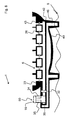
- FIG. 6 the side view of an integral accumulator complex with pressure vessel connection
- FIG. 7 an embodiment of the pumped storage power plant with multiple integral accumulator complexes
- FIG. 9 a schematic representation of the underwater pumped storage power plant from FIG. 8 with connected pressure vessels
- FIG. 10 a schematic representation of an embodiment of the integral accumulator complex
- FIG. 11 a schematic representation of another embodiment of the integral accumulator complex
- FIG. 12 a schematic representation of a shell of a base body
- FIG. 13 the base body shown in FIG. 12 with filler and prepared hollow spaces
- FIG. 15 a schematic representation of another embodiment of the underwater pumped storage power plant with two pump-turbine units
- FIG. 16 a schematic representation of yet another embodiment of the underwater pumped storage power plant with round pressure vessels.
- FIG. 1 first, the basic structure of the electrical networking of the pumped storage power plant 6 is shown schematically as an overview. Electrical energy is symbolically generated by means of a certain electrical power plant, in this example a wind turbine 2 .
- the wind turbine 2 is connected to the pumped storage power plant 6 by a power line 4 in order to carry the electrical energy from the primary power plant to the pumped storage power plant 6 .
- the pumped storage power plant 6 is located on the ocean floor 8 at a water depth T, which can be a few hundred to a few thousand meters depending on the existing geographic conditions.
- the pumped storage power plant 6 is also connected to a load 14 by a power line 12 in order to carry the electrical energy from the pumped storage power plant 6 to the load.
- the wind turbine 2 shown can representatively stand for a plurality of wind turbines, and that other renewable, fluctuating energy plants such as photovoltaic systems, etc. can also be used.
- the load 14 representatively stands for a plurality of loads that are connected to the existing part of the general power supply network into which the recovered electrical energy from the pumped storage power plant 6 is fed when the demand exceeds the power output provided by the primary power plants.
- the illustrated power lines 4 and 12 representatively stand for the connection to the general power supply network with its integration of power sources and power sinks.
- the pumped storage power plant 6 is connected by a cable 52 to a floating buoy 54 so that the pumped storage power plant 6 can be easily detected even at the water surface and, if applicable, brought to the surface using the cable 52 .
- multiple pressure vessels 20 are connected to the centrally located sump 24 by pressure vessel connections 22 , which in the embodiment shown constitute both inflow and outflow for the applicable pressure vessel 20 , and together the vessels form the accumulator system 30 .
- the pressure vessel connections 22 can each be closed with a shutoff valve 26 so that individual pressure vessels 20 can be disconnected and brought to the surface, for example for maintenance purposes.
- the sump 24 is located directly at the pump-turbine unit 60 .
- water is pumped out of the internal cavities 18 of the pressure vessels 20 into the surrounding ocean 1 by means of a pump 16 (not shown) located in the pump-turbine unit 60 .
- E (kW) V (m 3 ) ⁇ T (m) ⁇ 9.81/3600
- a power output of approximately 10 megawatts can be delivered over a time period of 6 hours.
- a daily cycle of recharging the pump storage by wind power or photovoltaic energy which is to say daily filling and pumping out of the storage volume V, this results in a stored energy quantity of approximately 20,000 MWh per year.
- FIG. 3 shows the embodiment from FIG. 2 in a side view, with the cylindrical shape of the pressure vessels 20 and the central arrangement of the pump-turbine element 60 made even clearer.
- the pressure vessels 20 are connected to the central pump-turbine element 60 by means of pressure vessel connections 22 .
- FIG. 4 shows an alternative embodiment of the accumulator system with an integrated accumulator complex 20 a .
- a plurality of internal pressure vessel elements 19 form a common accumulator volume 20 a , and are connected to one another at one end of the integrated accumulator complex 20 a . In the case of a standing arrangement, this end is the bottom of the integrated accumulator complex, which thus already forms the sump 24 of the accumulator complex, where the water of the pressure vessel elements 19 can flow together.
- the pressure vessel elements 19 are composed of pipes, for example, steel pipes or fiber-reinforced concrete pipes, that are arranged upright next to one another. The outer wall 28 is then cast around the pipes such that the hollow spaces and the region directed outward toward the ocean water 1 are filled.
- the material thickness of the pipes is either chosen such that it is sufficient to withstand the pressure of the water column present outside so that the outer wall 28 secures the pipes against falling for the purposes of statics, and additionally weights the structure for sinking to the ocean floor 8 , or the material thickness of the pressure vessel elements 19 can be chosen to be thinner so that the outer wall 28 of the integrated accumulator complex 20 a simultaneously also withstands the pressure of the water column present outside.
- FIG. 5 shows an embodiment of the pressure vessel 20 similar to the one in FIG. 4 as an integrated accumulator complex 20 a , wherein the volume enclosed by the outer wall 28 is optimally utilized by the selection of different, appropriate pipe diameters of the individual internal pressure vessel elements 19 .
- the smaller hollow spaces shown in the outer region of the integrated accumulator complex 20 a are also suitable for being weighted or filled with a ballast.
- FIG. 6 shows a side view of an integrated accumulator complex 20 a with a plurality of pressure vessel elements 19 and an outer wall 28 enclosing the pressure vessel elements 19 .
- the integrated accumulator complex 20 a has, at the bottom, a sump 24 of the accumulator complex, and is hydraulically connected to a central pump-turbine unit 60 (see FIG. 7 ) by a pressure vessel connection 22 .
- the pressure vessel connection 22 is thus also the water inlet and water outlet of the integrated accumulator complex 20 a , and can also be connected to additional pressure vessels 20 (not shown).
- the integrated accumulator complex 20 a has no moving mechanical parts or components of the power electronics for power generation or power dissipation.
- FIG. 7 shows a schematic top view of an underwater pumped storage power plant 6 with a central pump-turbine unit 60 , and connected thereto by pressure vessel connections 22 , integral accumulator complexes 20 a , each having a plurality of pressure vessel elements 19 .
- the integral accumulator complexes 20 a have no moving parts, since both the pump 16 and the turbine 36 , as well as the shutoff valves 26 , are integrated at or in the pump-turbine unit 60 .
- the shutoff valves 26 can disconnect the integral accumulator complexes 20 a from the central pump-turbine unit 60 .
- the pump-turbine unit 60 also constitutes the hydrostatically lowest point at the pump 16 , the sump 24 , the point to which the water flows of its own accord because of gravity.
- a shutoff valve 26 is built into each side passage 43 so that the pressure vessels 20 installed at each of the connection couplings 23 of the side passages 43 can be shut off and disconnected from the base body 40 , for example for maintenance purposes.
- the shutoff valves 26 in the side passages 43 of the base body 40 also make it possible to use a universal base part in which individual connection couplings 23 remain unused in the event that only a smaller accumulator volume is required, so that the base bodies can be produced in large-scale production and can nevertheless be adapted to the applicable application area.
- an intake/discharge valve 32 and the shutoff valves 26 of the side passages 43 are opened, and water from the surrounding ocean with the hydrostatic pressure PT corresponding to the water depth T flows through a water inlet 34 and through the turbine 36 into the internal cavities 18 of the pressure vessels 20 , and hence into the common pumped storage volume, whereupon the energy stored by the pumping-out process can be recovered, less the usual output losses.
- the recovered electrical energy is fed into the general power supply network through the power line 12 .
- multiple water inlets 34 with valves 32 and turbines 36 may be present.
- the internal cavities 18 can be spanned by struts or a supporting framework (not shown).
- the transverse struts can perform a dual function in this design, firstly to stabilize the pressure vessel 20 , and secondly to create turbulence in the water flowing into the internal cavity 18 through the generator 36 in order to prevent resonant vibrations in the pressure vessel 20 .
- the pressure vessel 20 includes a tubular concrete wall 28 with a connection coupling 23 on the bottom, and if applicable another connection coupling 23 on the top, so that the pressure vessels 20 can be coupled to the base body 40 and additional pressure vessels 21 can be coupled to the pressure vessels 20 .
- the wall thickness of the pressure vessels 20 and the base body 40 is chosen as a function of the water depth T to which the pumped storage power plant 6 is sunk and as a function of the mass required so that it can still be sunk.
- the turbines 36 and the pumps 16 are located directly on the base body 40 , e.g., directly at the main passage 42 , or on an extension 44 of the base body 40 .
- the pump 16 , turbine 36 , and water inlet and outlet openings 34 , 26 are arranged such that they are integrated in a pump-turbine unit 60 .
- the water is conducted only over a short distance, namely only through the inlet and outlet openings 34 , 26 .
- the pumped storage power plant 6 requires only electrical lines 4 , 12 from the ocean surface to the ocean floor 8 , but not pipes or lines to transport water. If applicable, one electrical line can even suffice as the power supply and delivery line. It may be a further advantage that the pressure difference resulting from the great depth of water is not strongly dependent on the fill level within the pressure vessel 20 , so that the power output that is available is essentially constant regardless of the fill level.
- the base body 40 has hollow spaces 38 in its wall 28 that are filled with bulk material, e.g. sand, in order to tare the mass of the pumped storage power plant 6 .
- the pumped storage power plant 6 or its components including the base body 40 and pressure vessels 20 , is first tared so as to still barely float when pumped completely empty so that it can be transported by ship to the site where it is to be sunk. Then, at the sinking site, the base body 40 and/or the pressure vessel 20 is sufficiently weighted with ballast water that the pumped storage power plant 6 sinks.
- the base body 40 can be sunk first, and the pressure vessels 20 are then installed on the base body 40 on the ocean floor 8 , or else the pressure vessels 20 are attached to the connection couplings 23 of the base body 40 while still on the ocean surface, and the entire pumped storage power plant 6 is then sunk.
- the quantity of water used as ballast water is used only for weighting, and is not pumped out during normal operation, i.e. during storage and recovery of electrical energy, so that in normal operation the pumped storage power plant 6 always has a mass greater than the displaced water and hence remains on the ocean floor 8 .
- the ballast water can also be poured into the separate cavities 38 , however.
- the additional ballast water not provided for energy storage in normal operation can be pumped out, however, so that the pumped storage power plant 6 floats again or at least becomes light enough that it can be brought up, for example with the cable 52 , which is marked at the ocean surface with a floating buoy 54 (see FIG. 1 ).
- the base body 40 and pressure vessels 20 it is preferred that they be built floating in water, e.g., cast successively in sections from steel-reinforced concrete while floating. In so doing, the unfinished pressure vessel should project far enough from the water during manufacture that it is not possible for its interior cavity 18 to fill up even during a storm.
- the thickness of the wall 28 of the pressure vessel 20 must withstand the extremely high hydrostatic water pressure, and must also give the pressure vessel 20 a dead weight high enough that the pumped storage power plant 6 sinks to the ocean floor 8 with an at least nearly empty interior cavity 18 .
- Steel-reinforced concrete comes into consideration as a wall material.
- the structural analysis is carried out such that the pressure vessel 20 can withstand pressures higher than those present at the ocean floor 8 without damage.
- All components relevant to the system such as valves 26 , 32 , turbines 36 , pumps 16 , passages 42 , 43 , and/or electrical lines etc., are integrated into the base body 40 , and the pressure vessels 20 are equipped with connection couplings 23 so that they can later perform their function for many decades.
- the monitoring and control electronics are likewise arranged directly on the base body 40 and are sunk with it.
- FIG. 10 shows a side view of an integrated accumulator complex with multiple interior pressure vessel elements 19 , such as was presented in FIGS. 4 and 5 .
- the pressure vessel elements 19 are hydraulically connected to one another through a base body 40 and constitute a common accumulator volume.
- a cover 46 is placed on the top to close and seal the accumulator complex with respect to the surrounding seawater 1 .
- a pump-turbine unit 60 is arranged in the cover or in the base body 40 so that a separate pump and/or turbine does not need to be used for each of the pressure vessel elements 19 ; instead, the pressure vessel elements 19 share the common infrastructure of pump(s) 16 , turbine(s) 36 , and the electric power supply.
- the integrated accumulator complex with a plurality of pressure vessel elements 19 is thus an independent underwater pumped storage power plant 6 .
- a power supply network 48 is shown that has a plurality of networked loads 14 and a plurality of networked wind power stations 2 and photovoltaic systems 3 that form the primary power plants.
- the electric power generated by the primary power plants 2 , 3 is temporarily stored by means of a plurality of pumped storage power plants 6 from FIGS. 2 through 4 .
- the many pumped storage power plants 6 are networked on the ocean floor 8 solely by means of electric underwater lines 50 , and supply the recovered electrical energy as needed through the existing part of the power supply network 48 to the loads 14 .
- FIGS. 12 to 14 show a preferred manufacturing process in which, referring to FIG. 12 , an unfinished shell of the base body 40 is first produced at a dock or harbor. It is manufactured such that it always barely floats, and is then towed to some place in the ocean where it is sunk to the ocean floor with some ballast.
- the dock at the harbor can be used as formwork for the base body 40 under certain circumstances.
- connecting pipes to the turbine and to the pump that take on the function of the previously described main passage 42 and side passages 43 integrated into the base body 40 have already been laid in the base body 40 .
- a base weight or filler 41 has been poured into the base body 40 , which is to say that concrete, for example, has been poured in.
- the filler can enclose the main and side passages 42 , 43 in a simple manner.
- the base body 40 can still be in the harbor or dock used for manufacture, or can already be on the high seas. Shown are pressure vessels 20 and an additional pressure vessel 21 , which are placed on the filler 41 . In the simplest case, the pressure vessels 20 , 21 are placed on the base body 40 in the harbor by container crane and anchored.
- FIG. 15 shows another embodiment of the underwater pumped storage power plant. To begin with, it differs from the embodiment shown in FIG. 9 in that a second pump-turbine block 62 is arranged on the base body 40 ; this can increase the electricity production in parallel operation and/or increase reliability, for example.
- the base body in this embodiment includes two intake/discharge valves, located before the applicable pump-turbine block 60 , 62 , for separate operation of the pump-turbine block 60 and the second pump-turbine block 62 .
- the pressure vessels 20 are implemented as simple pipes that are connected to one another and have a common cover 46 at the top, which can likewise be simply cast from concrete, for example.
- the pressure vessels 20 are implemented as spherical pressure vessels 20 and have simple pressure vessel connections 22 .
- the pressure vessels are simply screwed to one another, for example.
Landscapes
- Engineering & Computer Science (AREA)
- Chemical & Material Sciences (AREA)
- Combustion & Propulsion (AREA)
- Mechanical Engineering (AREA)
- General Engineering & Computer Science (AREA)
- Power Engineering (AREA)
- Life Sciences & Earth Sciences (AREA)
- Sustainable Development (AREA)
- Sustainable Energy (AREA)
- Other Liquid Machine Or Engine Such As Wave Power Use (AREA)
- Wind Motors (AREA)
Applications Claiming Priority (4)
| Application Number | Priority Date | Filing Date | Title |
|---|---|---|---|
| DE102011118206A DE102011118206A1 (de) | 2011-11-11 | 2011-11-11 | Pumpspeicherkraftwerk |
| DE102011118206.7 | 2011-11-11 | ||
| DE102011118206 | 2011-11-11 | ||
| PCT/EP2012/072357 WO2013068577A1 (fr) | 2011-11-11 | 2012-11-12 | Installation de stockage d'énergie par pompage |
Publications (2)
| Publication Number | Publication Date |
|---|---|
| US20150361948A1 US20150361948A1 (en) | 2015-12-17 |
| US9797366B2 true US9797366B2 (en) | 2017-10-24 |
Family
ID=47221359
Family Applications (1)
| Application Number | Title | Priority Date | Filing Date |
|---|---|---|---|
| US14/357,328 Active US9797366B2 (en) | 2011-11-11 | 2012-11-12 | Pumped-storage power plant |
Country Status (5)
| Country | Link |
|---|---|
| US (1) | US9797366B2 (fr) |
| EP (1) | EP2776705B1 (fr) |
| JP (3) | JP5964979B2 (fr) |
| DE (1) | DE102011118206A1 (fr) |
| WO (1) | WO2013068577A1 (fr) |
Cited By (6)
| Publication number | Priority date | Publication date | Assignee | Title |
|---|---|---|---|---|
| US20190170109A1 (en) * | 2016-10-07 | 2019-06-06 | Littoral Power Systems Inc. | Pumped storage hydropower system |
| WO2019182458A1 (fr) | 2018-03-23 | 2019-09-26 | Hans Gude Gudesen | Système de stockage d'énergie sous marine |
| WO2022192386A1 (fr) * | 2021-03-09 | 2022-09-15 | American Exchanger Services, Inc. | Stockage d'énergie utilisant un ensemble récipient sous pression sphérique |
| US20220364539A1 (en) * | 2019-07-10 | 2022-11-17 | Schmidt Boecking Horst | Method for Constructing a Pumped Storage Power Plant in a Ground Depression, in Particular in an Open-Cast Mine |
| US11870253B2 (en) | 2021-12-03 | 2024-01-09 | Power8 Tech Inc. | Energy storage systems and methods using heterogeneous pressure media and interactive actuation module |
| US12085053B2 (en) | 2021-06-22 | 2024-09-10 | Riahmedia Inc. | Systems and methods for power distribution and harnessing of marine hydrokinetic energy |
Families Citing this family (19)
| Publication number | Priority date | Publication date | Assignee | Title |
|---|---|---|---|---|
| DE102013019776B3 (de) * | 2013-11-21 | 2015-01-29 | Gerhard Luther | Tiefschacht-Pumpspeicherkraftwerk (TS.PSKW) |
| DE102013020984A1 (de) * | 2013-12-12 | 2015-06-18 | Heinz Siemast | Stahlhohlkörpersysteme als Pumpspeicherwerk |
| DE102014000811A1 (de) | 2014-01-22 | 2014-05-08 | Rainer L.M. Klopp | Hochleistungs-Pumpspeicherkraftwerk |
| FR3036887B1 (fr) * | 2015-06-01 | 2017-07-14 | Segula Eng & Consulting | Dispositif et procede de conversion d'energie et de stockage d'energie d'origine electrique, sous forme d'air comprime |
| US20160248230A1 (en) * | 2016-04-28 | 2016-08-25 | Solar Turbines Incorporated | Modular power plant assembly |
| CN106594926A (zh) * | 2016-11-08 | 2017-04-26 | 广西大学 | 基于排水抗浮基础的地源热泵系统 |
| CA3104836A1 (fr) | 2017-03-21 | 2018-09-27 | Strong Force Iot Portfolio 2016, Llc | Systemes et procedes de plate-forme nucleaire fabriquee en chantier naval et livree en mer |
| GB2566037B (en) | 2017-08-30 | 2020-07-01 | Subsea 7 Norway As | Subsea energy storage |
| DE102018000481A1 (de) * | 2018-01-23 | 2019-07-25 | Bernd Finkbeiner | Micro - pumpspeicherwerk |
| GB2578451A (en) * | 2018-10-26 | 2020-05-13 | Subsea 7 Norway As | Generating electrical power underwater |
| WO2020239237A1 (fr) | 2019-05-31 | 2020-12-03 | Thesum Gmbh I.Gr. | Micro-centrale hydraulique d'accumulation par pompage |
| DE102019118726B4 (de) | 2019-07-10 | 2021-04-01 | Gerhard Luther | Verfahren zur vorläufigen Nutzung eines zumindest teilweise errichteten unteren Reservoirs für ein Unterwasser-Pumpspeicherkraftwerk |
| DE102020002609A1 (de) | 2020-04-30 | 2021-11-04 | Gerhard Luther | Unterwasser-PSKW im Tagebau-Restsee |
| DE102020111844A1 (de) * | 2020-04-30 | 2021-11-04 | Horst Schmidt-Böcking | Modulares Unterwasser-Pumpspeicherkraftwerk-Reservoir |
| JP7484525B2 (ja) | 2020-07-20 | 2024-05-16 | 株式会社大林組 | 蓄電システム |
| DE102020005091B4 (de) | 2020-08-19 | 2022-07-28 | Michael T. Witt | Hochdruck-Pumpspeicherkaftwerk-System |
| EP4198297A1 (fr) | 2021-12-20 | 2023-06-21 | Sulzer Management AG | Système de stockage d'énergie |
| US20230383718A1 (en) | 2022-05-31 | 2023-11-30 | Sulzer Management Ag | Energy storage system |
| CN116227238B (zh) * | 2023-05-08 | 2023-07-14 | 国网安徽省电力有限公司经济技术研究院 | 一种抽水蓄能电站运行监测管理系统 |
Citations (17)
| Publication number | Priority date | Publication date | Assignee | Title |
|---|---|---|---|---|
| US3939356A (en) * | 1974-07-24 | 1976-02-17 | General Public Utilities Corporation | Hydro-air storage electrical generation system |
| US3992881A (en) * | 1975-08-25 | 1976-11-23 | Scherrer William A | Apparatus to generate high pressure air from water |
| GB2032009A (en) | 1978-10-06 | 1980-04-30 | Grueb R | Apparatus for generating power from hydrostatic pressure |
| GB2069618A (en) | 1980-02-15 | 1981-08-26 | Energy Kinematics Inc | Method of, and apparatus for, utilising the kinetic energy associated with a hydraulic head |
| JPH03294662A (ja) | 1990-04-12 | 1991-12-25 | Tokyo Electric Power Co Inc:The | 発電装置 |
| JPH045475A (ja) | 1990-04-19 | 1992-01-09 | Mitsubishi Heavy Ind Ltd | 深海電力貯蔵プラント |
| JPH09317622A (ja) | 1996-05-31 | 1997-12-09 | Mitsubishi Heavy Ind Ltd | 深海電力貯蔵システム |
| JPH1037840A (ja) | 1996-07-22 | 1998-02-13 | Mitsubishi Heavy Ind Ltd | 海中電力貯蔵システム |
| US7281371B1 (en) * | 2006-08-23 | 2007-10-16 | Ebo Group, Inc. | Compressed air pumped hydro energy storage and distribution system |
| WO2009111861A1 (fr) | 2008-03-13 | 2009-09-17 | Parker V Martin | Système de génération et de stockage immergé (subgenstor) |
| JP2010159695A (ja) | 2009-01-08 | 2010-07-22 | Taiyo Plant Kk | 波エネルギー利用装置および該波エネルギー利用装置を使用した波エネルギー利用プラント |
| US7795748B2 (en) | 2007-11-30 | 2010-09-14 | Deangeles Steven J | System and process for generating hydroelectric power |
| US7911073B2 (en) | 2008-10-08 | 2011-03-22 | Todd Smith | System and method for a hydro-hydraulic gravitational generator |
| WO2011084164A1 (fr) | 2010-01-05 | 2011-07-14 | Horton Wison Deepwater, Inc. | Systèmes et procédés pour installation et retrait de stockage de gaz sous-marin |
| EP2345809A1 (fr) | 2010-01-19 | 2011-07-20 | Janne Aaltonen | Génération d'énergie hydro-électrique |
| WO2011112561A2 (fr) | 2010-03-08 | 2011-09-15 | Massachusetts Institute Of Technology | Système offshore permettant de récolter et de stocker de l'énergie et de générer de l'électricité |
| US8997475B2 (en) * | 2011-01-10 | 2015-04-07 | General Compression, Inc. | Compressor and expander device with pressure vessel divider baffle and piston |
Family Cites Families (5)
| Publication number | Priority date | Publication date | Assignee | Title |
|---|---|---|---|---|
| DE2843675C3 (de) * | 1978-10-06 | 1982-02-25 | Grüb, Rainer, Ing.(grad.), 7800 Freiburg | Vorrichtung zur Stromerzeugung mittels eines Windrades |
| JPH0715170B2 (ja) * | 1989-04-25 | 1995-02-22 | 鹿島建設株式会社 | 滑動免震式海洋構造物の施工方法 |
| JPH04140322A (ja) * | 1990-09-28 | 1992-05-14 | Kajima Corp | 変位抑制装置を有する重力着底式海洋構造物 |
| CA2618022C (fr) * | 2006-01-04 | 2017-07-11 | Daniel Farb | Methodes et dispositifs de conversion d'energie provenant des vagues de l'ocean, en puissance electrique |
| DE102011013329A1 (de) | 2011-03-08 | 2012-09-13 | Roentdek-Handels Gmbh | Pumpspeicherkraftwerk |
-
2011
- 2011-11-11 DE DE102011118206A patent/DE102011118206A1/de not_active Ceased
-
2012
- 2012-11-12 EP EP12790493.6A patent/EP2776705B1/fr active Active
- 2012-11-12 WO PCT/EP2012/072357 patent/WO2013068577A1/fr active Application Filing
- 2012-11-12 US US14/357,328 patent/US9797366B2/en active Active
- 2012-11-12 JP JP2014540499A patent/JP5964979B2/ja active Active
-
2016
- 2016-06-28 JP JP2016127139A patent/JP2016169742A/ja active Pending
-
2018
- 2018-05-30 JP JP2018102971A patent/JP6781199B2/ja active Active
Patent Citations (19)
| Publication number | Priority date | Publication date | Assignee | Title |
|---|---|---|---|---|
| US3939356A (en) * | 1974-07-24 | 1976-02-17 | General Public Utilities Corporation | Hydro-air storage electrical generation system |
| US3992881A (en) * | 1975-08-25 | 1976-11-23 | Scherrer William A | Apparatus to generate high pressure air from water |
| GB2032009A (en) | 1978-10-06 | 1980-04-30 | Grueb R | Apparatus for generating power from hydrostatic pressure |
| US4321475A (en) * | 1978-10-06 | 1982-03-23 | Grueb Rainer | Hydroelectric power generating arrangement |
| GB2069618A (en) | 1980-02-15 | 1981-08-26 | Energy Kinematics Inc | Method of, and apparatus for, utilising the kinetic energy associated with a hydraulic head |
| JPH03294662A (ja) | 1990-04-12 | 1991-12-25 | Tokyo Electric Power Co Inc:The | 発電装置 |
| JPH045475A (ja) | 1990-04-19 | 1992-01-09 | Mitsubishi Heavy Ind Ltd | 深海電力貯蔵プラント |
| JPH09317622A (ja) | 1996-05-31 | 1997-12-09 | Mitsubishi Heavy Ind Ltd | 深海電力貯蔵システム |
| JPH1037840A (ja) | 1996-07-22 | 1998-02-13 | Mitsubishi Heavy Ind Ltd | 海中電力貯蔵システム |
| US7281371B1 (en) * | 2006-08-23 | 2007-10-16 | Ebo Group, Inc. | Compressed air pumped hydro energy storage and distribution system |
| US7795748B2 (en) | 2007-11-30 | 2010-09-14 | Deangeles Steven J | System and process for generating hydroelectric power |
| WO2009111861A1 (fr) | 2008-03-13 | 2009-09-17 | Parker V Martin | Système de génération et de stockage immergé (subgenstor) |
| US7911073B2 (en) | 2008-10-08 | 2011-03-22 | Todd Smith | System and method for a hydro-hydraulic gravitational generator |
| JP2010159695A (ja) | 2009-01-08 | 2010-07-22 | Taiyo Plant Kk | 波エネルギー利用装置および該波エネルギー利用装置を使用した波エネルギー利用プラント |
| WO2011084164A1 (fr) | 2010-01-05 | 2011-07-14 | Horton Wison Deepwater, Inc. | Systèmes et procédés pour installation et retrait de stockage de gaz sous-marin |
| US20120260839A1 (en) * | 2010-01-05 | 2012-10-18 | Horton Wison Deepwater, Inc. | Systems and methods for subsea gas storage installation and removal |
| EP2345809A1 (fr) | 2010-01-19 | 2011-07-20 | Janne Aaltonen | Génération d'énergie hydro-électrique |
| WO2011112561A2 (fr) | 2010-03-08 | 2011-09-15 | Massachusetts Institute Of Technology | Système offshore permettant de récolter et de stocker de l'énergie et de générer de l'électricité |
| US8997475B2 (en) * | 2011-01-10 | 2015-04-07 | General Compression, Inc. | Compressor and expander device with pressure vessel divider baffle and piston |
Non-Patent Citations (7)
| Title |
|---|
| German Office Action, Applicant: Roentdek-Handels GmbH, DE Serial No. 10 2011 118206.7 DE Filing Date: Nov. 11, 2011, Date of Mailed: Aug. 29, 2012. |
| International Search Report and Written Opinion, Int. Serial No. PCT/EP2012/072357, Int. Filing Date: Nov. 11, 2012, Applicant: Roentdek-Handels GmbH, Date Mailed:. |
| Japanese Office Action with English Translation, Patent Application No. 2014-540499, Service No. 232957, Mail Date: May 26, 2015. |
| Japanese Office Action, Application No. 2016-127139, Date of Drafting: May 31, 2017. |
| JP 09-317622, Morishige, English translation of JP document. * |
| JP 10-37840, Morishige, English translation of JP document. * |
| Translation of International Preliminary Report on Patentability and Written Opinion, Int. Serial No. PCT/EP2012/072357, Int. Filing Date: Nov. 12, 2012, Applicant: Roentdek-Handels GmbH et al., Mail Date: May 22, 2014. |
Cited By (8)
| Publication number | Priority date | Publication date | Assignee | Title |
|---|---|---|---|---|
| US20190170109A1 (en) * | 2016-10-07 | 2019-06-06 | Littoral Power Systems Inc. | Pumped storage hydropower system |
| WO2019182458A1 (fr) | 2018-03-23 | 2019-09-26 | Hans Gude Gudesen | Système de stockage d'énergie sous marine |
| US11686284B2 (en) | 2018-03-23 | 2023-06-27 | Hans Gude Gudesen | Underwater energy storage system |
| US20220364539A1 (en) * | 2019-07-10 | 2022-11-17 | Schmidt Boecking Horst | Method for Constructing a Pumped Storage Power Plant in a Ground Depression, in Particular in an Open-Cast Mine |
| WO2022192386A1 (fr) * | 2021-03-09 | 2022-09-15 | American Exchanger Services, Inc. | Stockage d'énergie utilisant un ensemble récipient sous pression sphérique |
| US20220290818A1 (en) * | 2021-03-09 | 2022-09-15 | American Exchanger Services, Inc. | Energy Storage Using Spherical Pressure Vessel Assembly |
| US12085053B2 (en) | 2021-06-22 | 2024-09-10 | Riahmedia Inc. | Systems and methods for power distribution and harnessing of marine hydrokinetic energy |
| US11870253B2 (en) | 2021-12-03 | 2024-01-09 | Power8 Tech Inc. | Energy storage systems and methods using heterogeneous pressure media and interactive actuation module |
Also Published As
| Publication number | Publication date |
|---|---|
| EP2776705B1 (fr) | 2017-01-04 |
| JP2016169742A (ja) | 2016-09-23 |
| US20150361948A1 (en) | 2015-12-17 |
| JP6781199B2 (ja) | 2020-11-04 |
| EP2776705A1 (fr) | 2014-09-17 |
| JP2018132068A (ja) | 2018-08-23 |
| DE102011118206A1 (de) | 2013-05-16 |
| WO2013068577A1 (fr) | 2013-05-16 |
| JP5964979B2 (ja) | 2016-08-03 |
| JP2015504498A (ja) | 2015-02-12 |
Similar Documents
| Publication | Publication Date | Title |
|---|---|---|
| US9797366B2 (en) | Pumped-storage power plant | |
| US9617970B2 (en) | Pumped-storage power plant | |
| US10894660B2 (en) | Underwater energy storage system and power station powered therewith | |
| US10344741B2 (en) | Hydro-pneumatic energy storage system | |
| US8698338B2 (en) | Offshore energy harvesting, storage, and power generation system | |
| Slocum et al. | Ocean renewable energy storage (ORES) system: Analysis of an undersea energy storage concept | |
| US8274168B2 (en) | Generating hydroenergy | |
| US20100107627A1 (en) | Buoyancy energy storage and energy generation system | |
| US10364938B2 (en) | Underwater energy storage using compressed fluid | |
| US20160341173A1 (en) | Method for installing a so-called "marine" pumped-storage hydroelectric power plant and corresponding plant | |
| US11655794B2 (en) | Marine-pumped hydroelectric energy storage | |
| WO2007009192A1 (fr) | Système de génération d'énergie | |
| WO2024168403A1 (fr) | Centrale hydroélectrique | |
| AU2024201045A1 (en) | Hydropower plant | |
| CN118728621A (zh) | 一种海底压力罐下水库式可变速抽水蓄能电站 |
Legal Events
| Date | Code | Title | Description |
|---|---|---|---|
| AS | Assignment |
Owner name: ROENTDEK-HANDELS GMBH, GERMANY Free format text: ASSIGNMENT OF ASSIGNORS INTEREST;ASSIGNORS:SCHMIDT-BOECKING, HORST;LUTHER, GERHARD;SIGNING DATES FROM 20140605 TO 20140617;REEL/FRAME:033514/0346 |
|
| STCF | Information on status: patent grant |
Free format text: PATENTED CASE |
|
| CC | Certificate of correction | ||
| MAFP | Maintenance fee payment |
Free format text: PAYMENT OF MAINTENANCE FEE, 4TH YR, SMALL ENTITY (ORIGINAL EVENT CODE: M2551); ENTITY STATUS OF PATENT OWNER: SMALL ENTITY Year of fee payment: 4 |