US9795403B2 - Medical gripping tool - Google Patents
Medical gripping tool Download PDFInfo
- Publication number
- US9795403B2 US9795403B2 US13/150,957 US201113150957A US9795403B2 US 9795403 B2 US9795403 B2 US 9795403B2 US 201113150957 A US201113150957 A US 201113150957A US 9795403 B2 US9795403 B2 US 9795403B2
- Authority
- US
- United States
- Prior art keywords
- gripping
- metallic layer
- medical
- gripping tool
- tool
- Prior art date
- Legal status (The legal status is an assumption and is not a legal conclusion. Google has not performed a legal analysis and makes no representation as to the accuracy of the status listed.)
- Active, expires
Links
- PXHVJJICTQNCMI-UHFFFAOYSA-N Nickel Chemical compound [Ni] PXHVJJICTQNCMI-UHFFFAOYSA-N 0.000 claims description 22
- 238000000034 method Methods 0.000 claims description 11
- 229910052759 nickel Inorganic materials 0.000 claims description 11
- 230000000694 effects Effects 0.000 claims description 9
- RYGMFSIKBFXOCR-UHFFFAOYSA-N Copper Chemical compound [Cu] RYGMFSIKBFXOCR-UHFFFAOYSA-N 0.000 claims description 7
- 229910052802 copper Inorganic materials 0.000 claims description 7
- 239000010949 copper Substances 0.000 claims description 7
- 239000010410 layer Substances 0.000 description 135
- 238000004519 manufacturing process Methods 0.000 description 8
- 229910052751 metal Inorganic materials 0.000 description 8
- 239000002184 metal Substances 0.000 description 8
- 229910000679 solder Inorganic materials 0.000 description 6
- 239000002245 particle Substances 0.000 description 5
- 230000008901 benefit Effects 0.000 description 4
- 239000000463 material Substances 0.000 description 4
- XECAHXYUAAWDEL-UHFFFAOYSA-N acrylonitrile butadiene styrene Chemical compound C=CC=C.C=CC#N.C=CC1=CC=CC=C1 XECAHXYUAAWDEL-UHFFFAOYSA-N 0.000 description 3
- 239000004676 acrylonitrile butadiene styrene Substances 0.000 description 3
- 229920000122 acrylonitrile butadiene styrene Polymers 0.000 description 3
- 239000000835 fiber Substances 0.000 description 3
- 239000011159 matrix material Substances 0.000 description 3
- 239000004417 polycarbonate Substances 0.000 description 3
- OKTJSMMVPCPJKN-UHFFFAOYSA-N Carbon Chemical compound [C] OKTJSMMVPCPJKN-UHFFFAOYSA-N 0.000 description 2
- XEEYBQQBJWHFJM-UHFFFAOYSA-N Iron Chemical compound [Fe] XEEYBQQBJWHFJM-UHFFFAOYSA-N 0.000 description 2
- 229920000106 Liquid crystal polymer Polymers 0.000 description 2
- 239000004977 Liquid-crystal polymers (LCPs) Substances 0.000 description 2
- KDLHZDBZIXYQEI-UHFFFAOYSA-N Palladium Chemical compound [Pd] KDLHZDBZIXYQEI-UHFFFAOYSA-N 0.000 description 2
- 239000004696 Poly ether ether ketone Substances 0.000 description 2
- 239000004697 Polyetherimide Substances 0.000 description 2
- 239000004734 Polyphenylene sulfide Substances 0.000 description 2
- 239000004954 Polyphthalamide Substances 0.000 description 2
- 229910045601 alloy Inorganic materials 0.000 description 2
- 239000000956 alloy Substances 0.000 description 2
- 229910052799 carbon Inorganic materials 0.000 description 2
- 230000015271 coagulation Effects 0.000 description 2
- 238000005345 coagulation Methods 0.000 description 2
- 238000011161 development Methods 0.000 description 2
- 230000018109 developmental process Effects 0.000 description 2
- 230000006872 improvement Effects 0.000 description 2
- 238000001746 injection moulding Methods 0.000 description 2
- 150000002739 metals Chemical class 0.000 description 2
- 239000000203 mixture Substances 0.000 description 2
- 230000007935 neutral effect Effects 0.000 description 2
- BASFCYQUMIYNBI-UHFFFAOYSA-N platinum Chemical compound [Pt] BASFCYQUMIYNBI-UHFFFAOYSA-N 0.000 description 2
- 229920002530 polyetherether ketone Polymers 0.000 description 2
- 229920001601 polyetherimide Polymers 0.000 description 2
- 229920000069 polyphenylene sulfide Polymers 0.000 description 2
- 229920006375 polyphtalamide Polymers 0.000 description 2
- 230000008569 process Effects 0.000 description 2
- 230000001681 protective effect Effects 0.000 description 2
- 230000009467 reduction Effects 0.000 description 2
- 239000002356 single layer Substances 0.000 description 2
- 230000007704 transition Effects 0.000 description 2
- ZOXJGFHDIHLPTG-UHFFFAOYSA-N Boron Chemical compound [B] ZOXJGFHDIHLPTG-UHFFFAOYSA-N 0.000 description 1
- WKBOTKDWSSQWDR-UHFFFAOYSA-N Bromine atom Chemical compound [Br] WKBOTKDWSSQWDR-UHFFFAOYSA-N 0.000 description 1
- VYZAMTAEIAYCRO-UHFFFAOYSA-N Chromium Chemical compound [Cr] VYZAMTAEIAYCRO-UHFFFAOYSA-N 0.000 description 1
- VVQNEPGJFQJSBK-UHFFFAOYSA-N Methyl methacrylate Chemical compound COC(=O)C(C)=C VVQNEPGJFQJSBK-UHFFFAOYSA-N 0.000 description 1
- ZOKXTWBITQBERF-UHFFFAOYSA-N Molybdenum Chemical compound [Mo] ZOKXTWBITQBERF-UHFFFAOYSA-N 0.000 description 1
- 239000004677 Nylon Substances 0.000 description 1
- OAICVXFJPJFONN-UHFFFAOYSA-N Phosphorus Chemical compound [P] OAICVXFJPJFONN-UHFFFAOYSA-N 0.000 description 1
- 229920005372 Plexiglas® Polymers 0.000 description 1
- 239000004952 Polyamide Substances 0.000 description 1
- 239000004698 Polyethylene Substances 0.000 description 1
- BQCADISMDOOEFD-UHFFFAOYSA-N Silver Chemical compound [Ag] BQCADISMDOOEFD-UHFFFAOYSA-N 0.000 description 1
- NINIDFKCEFEMDL-UHFFFAOYSA-N Sulfur Chemical compound [S] NINIDFKCEFEMDL-UHFFFAOYSA-N 0.000 description 1
- ATJFFYVFTNAWJD-UHFFFAOYSA-N Tin Chemical compound [Sn] ATJFFYVFTNAWJD-UHFFFAOYSA-N 0.000 description 1
- RTAQQCXQSZGOHL-UHFFFAOYSA-N Titanium Chemical compound [Ti] RTAQQCXQSZGOHL-UHFFFAOYSA-N 0.000 description 1
- 238000005299 abrasion Methods 0.000 description 1
- 239000004760 aramid Substances 0.000 description 1
- 229920003235 aromatic polyamide Polymers 0.000 description 1
- 230000005540 biological transmission Effects 0.000 description 1
- 229910052796 boron Inorganic materials 0.000 description 1
- GDTBXPJZTBHREO-UHFFFAOYSA-N bromine Substances BrBr GDTBXPJZTBHREO-UHFFFAOYSA-N 0.000 description 1
- 229910052794 bromium Inorganic materials 0.000 description 1
- 239000000919 ceramic Substances 0.000 description 1
- 238000004140 cleaning Methods 0.000 description 1
- 230000001112 coagulating effect Effects 0.000 description 1
- 229910017052 cobalt Inorganic materials 0.000 description 1
- 239000010941 cobalt Substances 0.000 description 1
- GUTLYIVDDKVIGB-UHFFFAOYSA-N cobalt atom Chemical compound [Co] GUTLYIVDDKVIGB-UHFFFAOYSA-N 0.000 description 1
- 239000004020 conductor Substances 0.000 description 1
- 238000010276 construction Methods 0.000 description 1
- 238000010586 diagram Methods 0.000 description 1
- 238000005516 engineering process Methods 0.000 description 1
- 239000012530 fluid Substances 0.000 description 1
- 239000011521 glass Substances 0.000 description 1
- PCHJSUWPFVWCPO-UHFFFAOYSA-N gold Chemical compound [Au] PCHJSUWPFVWCPO-UHFFFAOYSA-N 0.000 description 1
- 229910052737 gold Inorganic materials 0.000 description 1
- 239000010931 gold Substances 0.000 description 1
- 239000008187 granular material Substances 0.000 description 1
- 230000036541 health Effects 0.000 description 1
- 229910052742 iron Inorganic materials 0.000 description 1
- 239000011859 microparticle Substances 0.000 description 1
- 238000012986 modification Methods 0.000 description 1
- 230000004048 modification Effects 0.000 description 1
- 229910052750 molybdenum Inorganic materials 0.000 description 1
- 239000011733 molybdenum Substances 0.000 description 1
- 239000002105 nanoparticle Substances 0.000 description 1
- 229920001778 nylon Polymers 0.000 description 1
- 210000000056 organ Anatomy 0.000 description 1
- 229910052763 palladium Inorganic materials 0.000 description 1
- 239000012994 photoredox catalyst Substances 0.000 description 1
- 229910052697 platinum Inorganic materials 0.000 description 1
- 229920002647 polyamide Polymers 0.000 description 1
- 229920000515 polycarbonate Polymers 0.000 description 1
- 229920000728 polyester Polymers 0.000 description 1
- -1 polyethylene Polymers 0.000 description 1
- 229920000573 polyethylene Polymers 0.000 description 1
- 239000012783 reinforcing fiber Substances 0.000 description 1
- 230000035945 sensitivity Effects 0.000 description 1
- RMAQACBXLXPBSY-UHFFFAOYSA-N silicic acid Chemical compound O[Si](O)(O)O RMAQACBXLXPBSY-UHFFFAOYSA-N 0.000 description 1
- 235000012239 silicon dioxide Nutrition 0.000 description 1
- 229910052709 silver Inorganic materials 0.000 description 1
- 239000004332 silver Substances 0.000 description 1
- 230000001954 sterilising effect Effects 0.000 description 1
- 239000000126 substance Substances 0.000 description 1
- 229910052717 sulfur Inorganic materials 0.000 description 1
- 239000011593 sulfur Substances 0.000 description 1
- 229910052718 tin Inorganic materials 0.000 description 1
- 239000011135 tin Substances 0.000 description 1
- 239000010936 titanium Substances 0.000 description 1
- 229910052719 titanium Inorganic materials 0.000 description 1
- WFKWXMTUELFFGS-UHFFFAOYSA-N tungsten Chemical compound [W] WFKWXMTUELFFGS-UHFFFAOYSA-N 0.000 description 1
- 229910052721 tungsten Inorganic materials 0.000 description 1
- 239000010937 tungsten Substances 0.000 description 1
Images


Classifications
-
- A—HUMAN NECESSITIES
- A61—MEDICAL OR VETERINARY SCIENCE; HYGIENE
- A61B—DIAGNOSIS; SURGERY; IDENTIFICATION
- A61B17/00—Surgical instruments, devices or methods
- A61B17/28—Surgical forceps
- A61B17/29—Forceps for use in minimally invasive surgery
-
- A—HUMAN NECESSITIES
- A61—MEDICAL OR VETERINARY SCIENCE; HYGIENE
- A61B—DIAGNOSIS; SURGERY; IDENTIFICATION
- A61B18/00—Surgical instruments, devices or methods for transferring non-mechanical forms of energy to or from the body
- A61B18/04—Surgical instruments, devices or methods for transferring non-mechanical forms of energy to or from the body by heating
- A61B18/12—Surgical instruments, devices or methods for transferring non-mechanical forms of energy to or from the body by heating by passing a current through the tissue to be heated, e.g. high-frequency current
- A61B18/14—Probes or electrodes therefor
- A61B18/1442—Probes having pivoting end effectors, e.g. forceps
- A61B18/1445—Probes having pivoting end effectors, e.g. forceps at the distal end of a shaft, e.g. forceps or scissors at the end of a rigid rod
-
- A—HUMAN NECESSITIES
- A61—MEDICAL OR VETERINARY SCIENCE; HYGIENE
- A61B—DIAGNOSIS; SURGERY; IDENTIFICATION
- A61B17/00—Surgical instruments, devices or methods
- A61B17/00234—Surgical instruments, devices or methods for minimally invasive surgery
- A61B2017/00345—Micromachines, nanomachines, microsystems
-
- A—HUMAN NECESSITIES
- A61—MEDICAL OR VETERINARY SCIENCE; HYGIENE
- A61B—DIAGNOSIS; SURGERY; IDENTIFICATION
- A61B17/00—Surgical instruments, devices or methods
- A61B2017/00982—General structural features
- A61B2017/00995—General structural features having a thin film
-
- A—HUMAN NECESSITIES
- A61—MEDICAL OR VETERINARY SCIENCE; HYGIENE
- A61B—DIAGNOSIS; SURGERY; IDENTIFICATION
- A61B17/00—Surgical instruments, devices or methods
- A61B17/28—Surgical forceps
- A61B17/29—Forceps for use in minimally invasive surgery
- A61B2017/2926—Details of heads or jaws
-
- A—HUMAN NECESSITIES
- A61—MEDICAL OR VETERINARY SCIENCE; HYGIENE
- A61B—DIAGNOSIS; SURGERY; IDENTIFICATION
- A61B18/00—Surgical instruments, devices or methods for transferring non-mechanical forms of energy to or from the body
- A61B2018/00053—Mechanical features of the instrument of device
- A61B2018/00107—Coatings on the energy applicator
- A61B2018/00125—Coatings on the energy applicator with nanostructure
-
- A—HUMAN NECESSITIES
- A61—MEDICAL OR VETERINARY SCIENCE; HYGIENE
- A61B—DIAGNOSIS; SURGERY; IDENTIFICATION
- A61B18/00—Surgical instruments, devices or methods for transferring non-mechanical forms of energy to or from the body
- A61B2018/00053—Mechanical features of the instrument of device
- A61B2018/00107—Coatings on the energy applicator
- A61B2018/00148—Coatings on the energy applicator with metal
Definitions
- the present invention relates to a medical gripping tool, in particular for micro-invasive operations, with a synthetic body and a metallic layer on a surface of the synthetic body, whereby the synthetic body is configured to be reshaped in the course of its expected use.
- the present invention relates to a method for handling a medical object, in particular in a micro-invasive operation, with the following steps: positioning on the medical object a medical gripping tool with a synthetic body and a metallic layer on a surface of the synthetic body; and reshaping the medical gripping tool in order to grip the medical object so that the synthetic body is reshaped.
- a gripping tool of this type and a method of this type are known from invention DE 20 2007 009 310 U1.
- patents DE 10 2007 026 721 A1 and DE 10 2010 009 259.2 shape-adapting medical gripping tools are described that are based on the fin-ray effect.
- the aforementioned patent DE 10 2007 026 721 A1 also discloses a gripping layer that is coated with micro- or nano-particles, which are not specified in further detail.
- Patent DE 10 2007 050 018 A1 discloses a medical gripping tool with spring elements in fluid chambers or for the support of gripping surfaces.
- Patent DE 698 32 497 T2 describes a medical gripping tool with a gripping layer that is coated with metallic granules that are not joined together.
- medical gripping tools made of synthetic have insufficient mechanical solidity.
- medical gripping tools of synthetic when required to transmit torque onto the medical object that is being held, show an undesired reshaping, in particular a torsion that cannot be reduced or eliminated except at considerable construction cost.
- Embodiments of the present invention are based on the idea of providing a medical gripping tool with a synthetic body and with a metallic layer on a surface of the synthetic body.
- Metallic layers on surfaces of synthetic bodies are already known from various fields in the art. There, they originally served mainly decorative purposes. Cost-effective production of injection-molded parts is meant to be combined with the assumption of a metallic component. A mechanical impact leads as a rule to tearing and chipping away of the metallic layer. Particles released by a medical instrument, however, constitute a considerable health risk for patients. It is therefore unthinkable in conventional terms to have a medical gripping tool with a synthetic body that is configured to be elastically reshaped in the expected application, and a metallic layer on a surface of the synthetic body.
- the aforementioned reshaping of the synthetic body is not merely a minor reshaping as occurs in particular in solid-state joints.
- This reshaping can be purely elastic or else partly elastic and partly structural. This does not mean a minor reshaping such as is unavoidable in impacts to every actual component.
- the synthetic body can be produced at reasonable cost, for example by the injection-molding method.
- the metallic layer on its surface depending on its properties and its manufacturing method, can also be obtained economically.
- the medical gripping instrument can thus involve such low overall production costs that it can be adopted for one-time use followed by disposal. This dispenses with the need for effort and costs for cleaning and sterilizing the gripping tool after each use.
- the metallic layer on the surface of the synthetic body makes certain defined mechanical properties possible.
- the metallic layer it is possible to achieve a high degree of mechanical stability, which can reduce torsion of the gripping tool to an acceptable quantity, also for example when torque is in effect. Sufficient mechanical stability can thus be achieved even with markedly smaller cross-sections on the synthetic body.
- the medical gripping tool can therefore be configured in markedly thinner or smaller format, for example, in some cases with equal gripping force.
- the metallic layer is configured to be structurally reshaped in the expected application.
- the metallic layer can consist of a single layer or can include a multi-layered system. Two-layered systems have proven themselves in the art with combinations and alloys of bromine, cobalt, molybdenum, nickel, chrome, gold, carbon, copper, palladium, phosphor, platinum, silver, sulfur, titanium, tungsten, tin, iron as well as oxides of these elements.
- the metallic layer or individual layers of a multi-layered system can each be microscopically homogeneous or can comprise a matrix with metallic or other particles embedded in it. In this case the matrix and the particles embedded in it comprise different materials.
- the particles embedded in the matrix in particular, likewise have sizes of at most 100 nm or at most 30 nm (in particular, 10 nm to 20 nm).
- the particles can likewise comprise combinations or alloys of the aforementioned elements.
- the synthetic body includes in particular a first gripping member, a second gripping member and a solid-state joint between the first and second gripping members.
- the aforementioned advantage of elasticity of the synthetic comes into play. While conventionally at least two gripping members and a shaft would have to be produced separately and then assembled, only one part needs to be produced here, and the assembly step can be dispensed with. The production costs, which as mentioned are comparatively low in any case, can be still further reduced. This makes it advantageous to configure the medical gripping tool for one-time use and subsequent disposal.
- At least either the first gripping member or the second gripping member can comprise a beam structure.
- a gripping member comprises several beams or studs and/or beam- or stud-shaped portions. Said beams and studs can each be either straight or curved and can comprise constant or varying cross-sections. Each set of three or four rods or studs can form a triangle or quadrilateral.
- the beam structure By means of the beam structure it is possible to obtain defined mechanical properties, which can be selected within broad boundaries, at comparatively low mass, in particular a particularly high rigidity or a defined elasticity.
- Both the rigidity and the elasticity of the beam structure can be selectively influenced by the metallic layer.
- the metal layer can comprise different layer thicknesses and/or different materials and/or different layer structures in different areas of the medical gripping tool.
- individual areas can be coated in order to increase their rigidity while one or more other areas are not coated, in order to maintain the elasticity of the synthetic body locally without reduction.
- At least either the first gripping member or the second gripping member can be configured to be reshaped during gripping of an object in accordance with the fin-ray effect.
- the fin-ray effect is the English term for this effect in the art. Similar medical gripping tools are described in patents DE 10 2007 026 721 A1 and DE 10 2010 009 259.2.
- a gripping tool that is based on the fin-ray effect has the particular advantage of defined and differentiated mechanical properties, as well as mechanical properties that vary from site to site within the gripping tool.
- a metallic layer on the synthetic body that is homogeneous with respect to its thickness and other properties can cause a marked improvement in this respect.
- the metal of the metallic layer as a rule comprises a markedly lower elasticity than the synthetic of the synthetic body. Because the metallic layer on the surface of the synthetic body, for example in the case of a stud or beam, is at the maximum distance from the neutral fiber of the beam, said layer has considerable influence on the pliability of the beam.
- the cross-section of the beam in particular the distance of the beam surface from the neutral fiber, therefore has a pronounced influence on the pliability of the beam when the described metallic layer is placed on the surface.
- the elastic reshaping is therefore still more strongly localized in the area of the reduced cross-section when a metallic layer is provided on the surface.
- the possibility of localizing the reshaping even more strongly at a solid-state joint by means of the metallic layer allows an even better definition of the kinematic properties of the medical gripping tool.
- the metallic layer comprises a varying thickness or another varying property or is not present at all, for example, in the area of the solid-state joints.
- the metallic layer has in particular an average granular size of at most 100 nm.
- the average granular size is the average size of the crystallites of the polycrystalline metallic layer. Because crystallites of the polycrystalline metallic layer, at least in exceptional cases, are of approximately spherical shape, the size of a crystallite is taken to be the equivalent diameter of the crystallite. The equivalent diameter in this case is the length of one edge of a quadratic hole of a grid through which the crystallite can just barely pass.
- an average granular size of at most 100 nm many metals comprise a markedly increased ductility in comparison with customary granular sizes, which are greater by several orders of magnitude. The risk of tearing or chipping away of the metallic layer is thus markedly reduced.
- An average granular size of at most 100 nm, and even more an average granular size of at most 30 nm or of 10 nm to 20 nm is particularly suited for the aforementioned configurations of the medical gripping tool in which the metallic layer is structurally reshaped in the expected application.
- the particular suitability stems primarily from the fact that the particularly high ductility can prevent tearing and chipping away of the metallic layer at repeated strong reshaping, for example in the area of a solid-state joint.
- the metallic layer can be present on a gripping surface of the gripping tool.
- the metallic layer is exclusively, or essentially exclusively, present on one or both gripping surfaces of the gripping tool.
- An electrically conductive metallic layer on a gripping surface of the gripping tool can make possible an electrical functioning of the gripping tool.
- a high-voltage alternating current of appropriate voltage and amplitude can be applied on the metallic layer on the gripping surface of the gripping tool in order to obliterate or sever tissue by coagulation.
- a gripping surface of the gripping tool it is possible on a gripping surface of the gripping tool to provide no metallic layer or a thinner metallic layer than at other areas of the surface of the gripping tool.
- the elasticity of the synthetic body in the area of the gripping surface can remain completely or largely intact. This can promote a protective or atraumatic gripping of tissue.
- the friction between the synthetic surface of the synthetic body and tissue can be greater than that between a metallic layer and tissue.
- a medical gripping tool as described here can be configured, for example, as a needle holder.
- the metallic layer makes possible a sufficiently rigid configuration of the needle holder in order to make possible the transmission of great forces onto the needle.
- a gripping surface of the needle holder that is not provided with the metallic layer can make possible a good force lock or friction lock between the needle holder or the synthetic body on the one hand and the needle on the other hand.
- the elasticity of the synthetic body on the gripping surface can be partly or predominantly maintained with a thin metallic layer, while electrical function is achieved at the same time.
- the metallic layer can markedly reduce the pliability of a portion of the synthetic body, for example a beam-shaped portion. Owing to the fact that in the area of a solid-state joint no metallic layer is present, or a thinner metallic layer is present than at other areas of the surface of the synthetic body, it is possible to maintain the elasticity of the synthetic body to its full extent in the area of the solid-state joint. Because in other areas the metallic layer can markedly reduce the elasticity of the synthetic body, the described configuration of the metallic layer makes possible a markedly good definition or limitation of the solid-state joint and thus also an especially defined kinematics of the medical gripping tool.
- a medical gripping tool as described here can, in addition, include a contacting device for electrical contacting of the metallic layer, whereby the metallic layer includes a portion on a gripping surface so that the portion on the gripping surface is connected in electrically conductive manner with the contacting device.
- the contacting device is, for example, a solder tail, a plug-in contact or a portion of the metallic layer that can be configured as especially thick.
- the portion on the gripping surface is configured, in particular, without an oxide layer or other electrically insulating layer.
- the contacting device and the portion of the metallic layer on the gripping surface are, for example, interconnected directly or by means of a conductor track or wire in electrically conductive manner.
- the described configuration of the medical gripping tool allows an electrical functioning, for example the severing and/or obliteration of tissue by coagulation.
- the metallic layer can include a nickel layer with an average granular size of at most 100 nm and a copper layer between the synthetic body and the nickel layer.
- the advantages of a small average granular size in the metallic layer have already been described and apply in particular to a nickel layer.
- the copper layer between the synthetic body and the nickel layer makes possible an especially durable and reliable fastening of the nickel layer to the surface of the synthetic body.
- the copper layer in particular, comprises an average granular size of at most 100 nm.
- a medical grip with a synthetic body and with a metallic layer on a surface of the synthetic body is positioned and reshaped on the medical object in order to grip the medical object, so that the synthetic body is reshaped.
- the metallic layer is structurally reshaped.
- metal-coated synthetic bodies were customarily configured in the art in such a way that in the expected application a minor elastic reshaping, at most, of the synthetic body occurred to prevent tearing and chipping of the metallic layer. It was recognized, however, that in a suitable configuration of the metallic layer, in particular in the aforementioned small granular sizes, the medical gripping tool can be completely configured so that in the expected application the metallic layer can even be structurally reshaped without risking tearing or chipping of the metallic layer.
- the synthetic body comprises, for example, ABS (acrylonitrile-butadiene-styrene), LCP (liquid crystal polymer), PA (polyamide), PC (polycarbonate), PEEK (polyetheretherketone), PEI (polyetherimide), PPA (polyphthalamide), PPS (polyphenylene sulfide) or a mixture of two or more of these synthetic substances, for example a mixture of PC and ABS.
- the synthetic body can, in addition, comprise reinforcing fibers, for example glass, basalt, boron, ceramic, silicic acid, aramid, carbon, polyester, nylon, polyethylene or plexiglass fibers.
- the metallic layer on the basis of its material, its surface structure or as a result of another antireflecting layer, can be configured in such a way that disturbing bright reflections of the illuminating light on the medical gripping tool are reduced or prevented.
- FIG. 1 shows a schematic depiction of a medical gripping tool of an embodiment of the present invention
- FIG. 2 shows a schematic depiction of another medical gripping tool of an embodiment of the present invention
- FIG. 3 shows a schematic depiction of another medial gripping tool of an embodiment of the present invention
- FIG. 4 shows a schematic depiction of another medial gripping tool of an embodiment of the present invention.
- FIG. 5 shows a schematic depiction of another medial gripping tool of an embodiment of the present invention.
- FIG. 6 shows a schematic depiction of another medial gripping tool of an embodiment of the present invention.
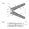
- FIG. 7 shows a schematic depiction of another medial gripping tool of an embodiment of the present invention.
- FIG. 8 shows a schematic depiction of a method for handling a medical object.
- FIG. 1 shows a schematic depiction of a section through a medical gripping tool 10 .
- a proximal end 11 of the medical gripping tool 10 is, for example, mechanically connected in (non-destructively) detachable or durable or destructively detachable manner with a distal end of a shaft that is not shown in FIG. 1 .
- the medical gripping tool 10 includes a first gripping member 14 and a second gripping member 15 , which are interconnected at the proximal end 11 of the medical gripping tool.
- Each of the gripping members 14 , 15 comprises a gripping surface 16 , 17 .
- the gripping surface 16 on the first gripping member 14 faces toward the second gripping member 15
- the gripping surface 17 on the second gripping member 15 faces toward the first gripping member 14 .
- the gripping members 14 , 15 starting from the position shown in FIG. 1 , can be moved toward one another until the gripping surfaces 16 , 17 touch one another.
- the medical gripping tool includes a synthetic body 20 , so that the first gripping member 14 and the second gripping member 15 each include a portion of the synthetic body 20 .
- the first gripping member 14 includes an external beam 23 and an internal beam 24 of the synthetic body 20 , which transition into one another distally. Reference is made hereinafter, using the terms “external” and “internal,” to distinguish marks or sides that are turned away from the gripping surfaces 16 , 17 or face toward the gripping surfaces 16 , 17 .
- a first stud 26 and a second stud 27 are positioned between the external beam 23 and the internal beam 24 of the first gripping member 14 .
- the first stud 26 and the second stud 27 are parallel or essentially parallel to one another.
- the first stud 26 and the second stud 27 can each be positioned perpendicular to the external beam 23 and to the internal beam 24 of the first gripping member 14 or, as shown in FIG. 1 , at a different angle.
- the second gripping member 15 can be configured as a mirror image, or essentially as a mirror image, of the first gripping member 14 and consequently is not described in further detail hereinafter.
- the external beam 23 of the first gripping member 14 and the corresponding external beam of the second gripping member 15 continue on the proximal end 11 of the gripping tool 10 into a proximal end 21 of the synthetic body 20 , by which they are mechanically interconnected.
- the proximal ends of the internal beam 24 of the first gripping member 14 and of the corresponding internal beam of the second gripping member 15 are not directly connected with the proximal end 21 of the synthetic body 20 .
- An area on the proximal end of the external beam 23 of the first gripping member 14 or a transition area between the proximal end 21 of the synthetic body 20 on the one hand and the external beam 23 of the first gripping member 14 forms a first solid-state joint 31 .
- An area of the first stud 26 adjoining the external beam 23 of the first gripping member 14 or a transitional area between the first stud 26 and the external beam 23 forms a second solid-state joint 32 .
- An area of the first stud 26 adjoining the internal beam 24 or a transitional area between the first stud 26 and the internal beam 24 forms a third solid-state joint 33 .
- Present on the second stud 27 are corresponding solid-state joints that are not identified with reference numbers of their own.
- a transitional area between the internal beam 24 of the first gripping member 14 and the corresponding internal beam of the second gripping member 15 forms a fourth solid-state joint 34 .
- a fourth solid-state joint 34 in the areas of the solid-state joints 31 , 32 , 33 , 34 reduced cross-sections are present in order to localize an elastic reshaping.
- a metallic layer 40 is present on the surface of the synthetic body 20 .
- the metallic layer 40 can include a single layer or a multi-layer system made of several partial layers.
- the metallic layer 40 includes a nickel layer with an average granular size of less than 100 nm, in particular with an average granular size in the range of 10 nm to 20 nm, and a copper layer between the synthetic body 20 and the nickel layer.
- the metallic layer 40 includes several areas that, as shown in FIG. 1 , continue into one another or, contrary to the depiction in FIG. 1 , can be severed from one another by gaps.
- a first portion or area 41 of the metallic layer 40 is present on the external surface of the external beam 23 .
- a second portion or area 42 of the metallic layer 40 is present on the internal surface of the external beam 23 .
- a third portion or area 43 of the metallic layer 40 is present on the external surface of the internal beam 24 .
- a fourth portion or area 44 of the metallic layer 40 is present on the internal surface of the internal beam 24 or on the gripping surface 16 of the first gripping member 14 .
- a fifth portion 45 of the metallic layer 40 is present on the surface of the first stud 26 .
- Corresponding areas of the metallic layer 40 are present on the second stud 27 and on the second gripping member 15 .
- the synthetic body 20 and the metallic layer 40 are elastically reshapable, in particular in the areas of the solid-state joints 31 , 32 , 33 , 34 .
- the medical gripping tool 10 can be configured in such a way that in the expected application the synthetic body 20 is reshaped elastically and the metallic layer 40 is reshaped partly only elastically and partly also structurally.
- the medical gripping tool 10 can be configured in such a way that the metallic layer 40 is structurally reshaped in the expected application in the areas of the solid-state joints 31 , 32 , 33 , 34 .
- the medical gripping tool 10 can, in particular, be reshaped in such a way that the gripping members 14 , 15 are moved toward one another until the gripping surfaces 16 , 17 touch one another or a medical object that is placed between them.
- the fourth solid-state joint 34 in particular is pulled in the proximal direction between the internal beams 24 of both gripping members 14 , 15 by means of a device not shown in FIG. 1 .
- the gripping members 14 , 15 can be reshaped according to the fin-ray effect.
- the medical gripping tool 10 or its gripping members 14 , 15 can, in particular, be configured so that, in gripping a convex object, they surround it in each case in an arc shape.
- the metallic layer 40 influences the mechanical properties of the gripping members 14 , 15 , in particular their elasticity and their reshaping upon gripping a medical object.
- the metallic layer 40 at the same time influences the mechanical properties of the medical gripping tool 10 at various sites in different ways. Contrary to the illustration in FIG. 1 , the metallic layer 40 can comprise various properties in various areas, for example different layer structures, materials, layer thicknesses. In addition, the metallic layer 40 can perform electrical functions and for this purpose can be configured differently in various areas of the medical gripping tool 10 .
- FIGS. 2 through 5 Additional embodiments of the medical gripping tool 10 are presented hereinafter with reference to FIGS. 2 through 5 .
- the two gripping members 14 , 15 are shown symmetrically in similar manner as in FIG. 1 . Contrary to that depiction, however, the two gripping members 14 , 15 can differ in configuration with respect to both the synthetic body 20 and the metallic layer 40 .
- FIG. 2 shows a schematic depiction of a medical gripping tool 10 , which resembles in some characteristics the medical gripping tool described above with reference to FIG. 1 , particularly with respect to the synthetic body 20 .
- the medical gripping tool 10 shown in FIG. 2 only the first area 41 of the metallic layer 40 on the external surface of the external beam 23 and the fourth area 44 of the metallic layer 40 on the gripping surfaces 16 , 17 are present. No metallic layer is present on the internal surface of the external beam 23 , on the external surface of the internal beam 24 and on the studs 26 , 27 .
- this configuration of the medical gripping tool 10 it is possible, for example, to generate especially high elasticity of the studs 26 , 27 and simultaneously an especially high tractive rigidity of the beams 23 , 24 .
- FIG. 3 shows a schematic depiction of an additional medical gripping tool 10 , which resembles in some characteristics the medical gripping tool presented above with reference to FIG. 2 .
- the metallic layer 40 in the first area 41 on the external surface of the external beam 23 is thicker in configuration than in the fourth area 44 on the internal surface of the internal beam 24 .
- the pliability of the internal beam 24 can be higher or essentially higher than that of the external beam 23 .
- the metallic layer 40 in the fourth area 44 on the gripping surface 16 can be dispensed with altogether. With the thin metallic layer in the fourth area 44 on the internal surface of the internal beam 24 as shown in FIG. 3 , it is possible simultaneously to ensure sufficient elasticity of the internal beam 24 and to allow electrical functionality.
- FIG. 4 presents a schematic depiction of an additional medical gripping tool 10 , which resembles in some characteristics the medical gripping tool presented above with reference to FIG. 1 and, in particular, the medical gripping tools presented above with reference to FIGS. 2 and 3 .
- the medical gripping tool 10 in FIG. 4 comprises a metallic layer 40 only on the gripping surfaces 16 , 17 .
- This metallic layer 40 in the fourth area 44 on the gripping surfaces 16 , 17 makes possible an electrical functionality and/or a reduced elasticity, in particular a reduced ductility or contractibility, of the internal beam 24 .
- the gripping tool illustrated in FIG. 4 in addition comprises an electrical plug-in contact 61 on the distal end 11 and a wire or cord 62 .
- the wire or cord 62 is embedded in the synthetic body 20 , in particular molded to it, and connects the electrical plug-in contact 61 by electrically conductive means with the metallic layer 40 .
- the wire or cord 62 is situated on the distal end of the gripping member 14 on the gripping surface 16 , where it touches the metallic layer 40 .
- the wire or cord 62 can be configured to influence the mechanical properties of the synthetic body, in particular of the external beam 23 .
- FIG. 5 presents a schematic depiction of a medical gripping tool 10 that, in particular, resembles in a few characteristics the medical gripping tool illustrated above in FIG. 1 .
- the medical gripping tool 10 of FIG. 5 comprises no metallic layer on the gripping surfaces 16 , 17 .
- a metallic layer can be present on the gripping surfaces 16 , 17 , which can be thinner than in the other areas 41 , 42 , 43 , 45 .
- the medical gripping tool 10 of FIG. 5 is differentiated from the medical gripping tool illustrated in FIG. 1 in that the metallic layer 40 comprises spaces or gaps 51 , 52 , 53 , 54 in the areas of the solid-state joints 31 , 32 , 33 , 34 .
- the metallic layer 40 reduces the elasticity of the medical gripping tool 10 .
- the reshaping of the medical gripping tool 10 is more markedly localized than in the medical gripping tool illustrated in FIG.
- the kinematic properties of the medical gripping tool 10 are therefore better defined or more independent of the forces and moments that occur in gripping a real object.
- FIG. 6 shows a schematic depiction of an additional medical gripping tool 10 with a first gripping member 14 and a second gripping member 15 .
- the medical gripping tool 10 shown in FIG. 6 comprises in each case teeth or a cannelure 18 .
- the gripping members 14 , 15 of the medical gripping tool 10 shown in FIG. 6 do not comprise a beam structure.
- the gripping members 14 , 15 are interconnected by solid-state joints 36 , 37 , 38 . Because the center solid-state joint 37 , which connects the gripping surfaces 16 , 17 of the gripping members 14 , 15 directly with one another, is pulled in the proximal direction, the gripping members 14 , 15 can be moved toward one another.
- the metallic layer 40 can increase the mechanical rigidity of the gripping members 14 , 15 and/or make electrical functionality possible.
- the metallic layer can, for example, be present on the entire surface of the gripping members 14 , 15 or only on the outsides of the gripping members 14 , 15 .
- the metallic layer 40 is connected in electrically conductive manner with a solder tail 63 by means of a conducting track 48 .
- the conducting track 48 can be a component of the metallic layer 40 and, in particular, can be produced simultaneously with it.
- the metallic layer can be contacted by the solder tail 63 , for example to apply an alternating current of appropriate voltage and amplitude for coagulating tissue.
- FIG. 7 shows a schematic depiction of a medical gripping tool 10 , which resembles in a few characteristics the medical gripping tool illustrated above in FIG. 6 .
- the medical gripping tool of FIG. 7 comprises conventional joints with shafts 66 , 67 instead of two solid-state joints.
- the gripping members 14 , 15 are pivotally or rotatably connected by the shafts 66 , 67 with a distal end 68 of a shaft of a medical instrument that is only referred to in FIG. 7 .
- the medical gripping tool 10 can be the medical instrument or a part of the medical instrument.
- the metallic layer 40 is connected in electrically conductive manner with a solder tail 63 by means of a conducting track 48 .
- Each of the two medical gripping tools illustrated in FIGS. 6 and 7 can comprise, instead of a solder tail, an electrical plug-in contact or any other type of contacting device.
- Each of the medical gripping tools illustrated in FIGS. 1 through 3 and 5 through 7 can comprise a plug-in contact as illustrated above in FIG. 4 , a solder tail as shown in FIGS. 6 and 7 , or other contacting devices.
- a medical gripping tool that, as shown in FIGS. 1 through 3 , comprises a metallic layer extending from the gripping surfaces 16 , 17 to the proximal end 11 , said metallic layer can be contacted on the proximal end 11 , for example by means of a clamp.
- the medical gripping tools illustrated above in FIGS. 1 through 5 can comprise cannelures on the gripping surfaces 16 , 17 , in similar manner as the gripping tools illustrated in FIGS. 6 and 7 .
- the medical gripping tools shown above in FIGS. 6 and 7 similarly as the gripping tools shown in FIGS. 1 through 5 , can comprise smooth, or essentially smooth, gripping surfaces 16 , 17 .
- the solid-state joints can be replaced partly by conventional joints with shafts.
- FIG. 8 shows a schematic flow diagram of a method for handling a medical object.
- the method can be executed in particular with medical gripping tools as shown above in FIGS. 1 through 7 .
- the method can also be executed with medical gripping tools that differ from those shown above in FIGS. 1 through 7 .
- the ensuing use of reference numbers from FIGS. 1 through 7 therefore serves only by way of example for the sake of clarity.
- a medical gripping tool 10 with a synthetic body 20 and a metallic layer 40 on a surface of the synthetic body 20 is positioned on the medical object.
- the medical gripping tool is reshaped in order to grip the medical object, whereby the synthetic body is reshaped at least elastically.
- the metallic layer 40 can be reshaped partly elastically and partly structurally.
- the reshaping in the second step 102 in particular, is not only inessential, as occurs in particular at solid-state joints.
- the gripping tool is reshaped in particular according to the fin-ray effect.
Landscapes
- Health & Medical Sciences (AREA)
- Surgery (AREA)
- Life Sciences & Earth Sciences (AREA)
- Biomedical Technology (AREA)
- Nuclear Medicine, Radiotherapy & Molecular Imaging (AREA)
- Engineering & Computer Science (AREA)
- Ophthalmology & Optometry (AREA)
- Heart & Thoracic Surgery (AREA)
- Medical Informatics (AREA)
- Molecular Biology (AREA)
- Animal Behavior & Ethology (AREA)
- General Health & Medical Sciences (AREA)
- Public Health (AREA)
- Veterinary Medicine (AREA)
- Surgical Instruments (AREA)
Applications Claiming Priority (3)
| Application Number | Priority Date | Filing Date | Title |
|---|---|---|---|
| DE102010022431A DE102010022431A1 (de) | 2010-06-01 | 2010-06-01 | Medizinisches Greifwerkzeug |
| DE102010022431 | 2010-06-01 | ||
| DE102010022431.6 | 2010-06-01 |
Publications (2)
| Publication Number | Publication Date |
|---|---|
| US20110295314A1 US20110295314A1 (en) | 2011-12-01 |
| US9795403B2 true US9795403B2 (en) | 2017-10-24 |
Family
ID=44117764
Family Applications (1)
| Application Number | Title | Priority Date | Filing Date |
|---|---|---|---|
| US13/150,957 Active 2033-12-25 US9795403B2 (en) | 2010-06-01 | 2011-06-01 | Medical gripping tool |
Country Status (3)
| Country | Link |
|---|---|
| US (1) | US9795403B2 (de) |
| EP (1) | EP2392272B1 (de) |
| DE (1) | DE102010022431A1 (de) |
Cited By (1)
| Publication number | Priority date | Publication date | Assignee | Title |
|---|---|---|---|---|
| US12521138B2 (en) | 2022-04-04 | 2026-01-13 | Covidien Lp | Surgical tissue grasper including a compliant jaw assembly |
Families Citing this family (12)
| Publication number | Priority date | Publication date | Assignee | Title |
|---|---|---|---|---|
| US8962062B2 (en) | 2012-01-10 | 2015-02-24 | Covidien Lp | Methods of manufacturing end effectors for energy-based surgical instruments |
| US20140012305A1 (en) * | 2012-07-05 | 2014-01-09 | Clinical Innovations, Llc | Colpotomy cup-like structure and intrauterine manipulator including same |
| EP2735406B1 (de) * | 2012-11-27 | 2018-04-04 | FESTO AG & Co. KG | Greifeinrichtung zum Greifen von Objekten |
| DE102013107972A1 (de) * | 2013-07-25 | 2015-02-19 | Karl Storz Gmbh & Co. Kg | Medizinisches Greifwerkzeug |
| WO2016104051A1 (ja) * | 2014-12-24 | 2016-06-30 | オリンパス株式会社 | 把持処置ユニット及び把持処置具 |
| US10226269B2 (en) | 2015-05-27 | 2019-03-12 | Covidien Lp | Surgical forceps |
| US10441340B2 (en) | 2015-05-27 | 2019-10-15 | Covidien Lp | Surgical forceps |
| EP3302306B1 (de) | 2015-05-27 | 2020-07-22 | Coloplast A/S | Greifwerkzeug |
| EP3244822B1 (de) | 2015-10-13 | 2018-12-19 | Brainlab AG | Einstellbare bahnführung |
| USD831825S1 (en) | 2016-06-21 | 2018-10-23 | Covidien Lp | Electrosurgical jaws |
| USD819816S1 (en) | 2016-06-21 | 2018-06-05 | Covidien Lp | Electrosurgical jaws |
| US11857247B2 (en) * | 2020-07-17 | 2024-01-02 | Cilag Gmbh International | Jaw for surgical instrument end effector |
Citations (20)
| Publication number | Priority date | Publication date | Assignee | Title |
|---|---|---|---|---|
| US4274413A (en) | 1978-10-06 | 1981-06-23 | Hahn Robert H | Depilatory tweezer |
| US5147378A (en) * | 1991-03-05 | 1992-09-15 | Harold Markham | Grapsing forceps |
| US5638827A (en) * | 1994-02-01 | 1997-06-17 | Symbiosis Corporation | Super-elastic flexible jaws assembly for an endoscopic multiple sample bioptome |
| US5746770A (en) * | 1995-11-22 | 1998-05-05 | Zeitels; Jerrold Roy | Endoscopic retriever |
| US6059783A (en) * | 1997-06-26 | 2000-05-09 | Kirwan Surgical Products, Inc. | Electro-surgical forceps which minimize or prevent sticking of tissue |
| EP1201198A1 (de) | 2000-10-27 | 2002-05-02 | MicroNet Medical, Inc. | Katheter mit Dünnschichtelektroden und Verfahren zur Herstellung |
| US20030069571A1 (en) * | 1997-03-05 | 2003-04-10 | Treat Michael R. | Electrothermal instrument for sealing and joining or cutting tissue |
| US20030158549A1 (en) * | 2002-02-19 | 2003-08-21 | Swanson David K. | Apparatus for securing an electrophysiology probe to a clamp |
| US20030171748A1 (en) | 2001-10-22 | 2003-09-11 | Sciogen Llc | Electrosurgical instrument and method of use |
| DE20318845U1 (de) | 2003-12-02 | 2004-03-25 | Grießbach, Volker, Dr.-Ing. | Handhabevorrichtung für dreidimensionale Objekte |
| DE69832497T2 (de) | 1997-02-03 | 2006-08-03 | Applied Medical Resources Corp., Rancho Santa Margarita | Chirurgische instrumente mit verbesserter zugfähigkeit |
| DE202007009310U1 (de) | 2007-06-26 | 2007-08-30 | Aesculap Ag & Co. Kg | Chirurgisches Instrument |
| DE102007026721A1 (de) | 2006-06-09 | 2008-05-15 | Fachhochschule Münster | Werkzeug zum Greifen, Halten, Bearbeiten oder Untersuchen von Körperbestandteilen |
| DE102007050018A1 (de) | 2006-10-17 | 2008-05-15 | Fachhochschule Münster | Greifwerkzeug |
| US7377920B2 (en) * | 1997-11-14 | 2008-05-27 | Sherwood Services Ag | Laparoscopic bipolar electrosurgical instrument |
| US7628792B2 (en) * | 2004-10-08 | 2009-12-08 | Covidien Ag | Bilateral foot jaws |
| US20100159260A1 (en) * | 2008-12-23 | 2010-06-24 | E. I. Du Pont De Nemours And Company | Chrome-free method of conditioning and etching of a thermoplastic substrate for metal plating |
| US20100263500A1 (en) * | 2009-04-19 | 2010-10-21 | Karl Storz Gmbh & Co. Kg | Manipulator tool and holding and/or expanding tool with at least one manipulator tool |
| US20100298864A1 (en) * | 2009-01-15 | 2010-11-25 | Michael Castro | Articulating rigid grasper |
| US7935052B2 (en) * | 2004-09-09 | 2011-05-03 | Covidien Ag | Forceps with spring loaded end effector assembly |
Family Cites Families (1)
| Publication number | Priority date | Publication date | Assignee | Title |
|---|---|---|---|---|
| DE102010009259A1 (de) | 2010-02-25 | 2011-08-25 | Karl Storz GmbH & Co. KG, 78532 | Medizinisches Instrument |
-
2010
- 2010-06-01 DE DE102010022431A patent/DE102010022431A1/de not_active Withdrawn
-
2011
- 2011-05-13 EP EP11165953.8A patent/EP2392272B1/de active Active
- 2011-06-01 US US13/150,957 patent/US9795403B2/en active Active
Patent Citations (20)
| Publication number | Priority date | Publication date | Assignee | Title |
|---|---|---|---|---|
| US4274413A (en) | 1978-10-06 | 1981-06-23 | Hahn Robert H | Depilatory tweezer |
| US5147378A (en) * | 1991-03-05 | 1992-09-15 | Harold Markham | Grapsing forceps |
| US5638827A (en) * | 1994-02-01 | 1997-06-17 | Symbiosis Corporation | Super-elastic flexible jaws assembly for an endoscopic multiple sample bioptome |
| US5746770A (en) * | 1995-11-22 | 1998-05-05 | Zeitels; Jerrold Roy | Endoscopic retriever |
| DE69832497T2 (de) | 1997-02-03 | 2006-08-03 | Applied Medical Resources Corp., Rancho Santa Margarita | Chirurgische instrumente mit verbesserter zugfähigkeit |
| US20030069571A1 (en) * | 1997-03-05 | 2003-04-10 | Treat Michael R. | Electrothermal instrument for sealing and joining or cutting tissue |
| US6059783A (en) * | 1997-06-26 | 2000-05-09 | Kirwan Surgical Products, Inc. | Electro-surgical forceps which minimize or prevent sticking of tissue |
| US7377920B2 (en) * | 1997-11-14 | 2008-05-27 | Sherwood Services Ag | Laparoscopic bipolar electrosurgical instrument |
| EP1201198A1 (de) | 2000-10-27 | 2002-05-02 | MicroNet Medical, Inc. | Katheter mit Dünnschichtelektroden und Verfahren zur Herstellung |
| US20030171748A1 (en) | 2001-10-22 | 2003-09-11 | Sciogen Llc | Electrosurgical instrument and method of use |
| US20030158549A1 (en) * | 2002-02-19 | 2003-08-21 | Swanson David K. | Apparatus for securing an electrophysiology probe to a clamp |
| DE20318845U1 (de) | 2003-12-02 | 2004-03-25 | Grießbach, Volker, Dr.-Ing. | Handhabevorrichtung für dreidimensionale Objekte |
| US7935052B2 (en) * | 2004-09-09 | 2011-05-03 | Covidien Ag | Forceps with spring loaded end effector assembly |
| US7628792B2 (en) * | 2004-10-08 | 2009-12-08 | Covidien Ag | Bilateral foot jaws |
| DE102007026721A1 (de) | 2006-06-09 | 2008-05-15 | Fachhochschule Münster | Werkzeug zum Greifen, Halten, Bearbeiten oder Untersuchen von Körperbestandteilen |
| DE102007050018A1 (de) | 2006-10-17 | 2008-05-15 | Fachhochschule Münster | Greifwerkzeug |
| DE202007009310U1 (de) | 2007-06-26 | 2007-08-30 | Aesculap Ag & Co. Kg | Chirurgisches Instrument |
| US20100159260A1 (en) * | 2008-12-23 | 2010-06-24 | E. I. Du Pont De Nemours And Company | Chrome-free method of conditioning and etching of a thermoplastic substrate for metal plating |
| US20100298864A1 (en) * | 2009-01-15 | 2010-11-25 | Michael Castro | Articulating rigid grasper |
| US20100263500A1 (en) * | 2009-04-19 | 2010-10-21 | Karl Storz Gmbh & Co. Kg | Manipulator tool and holding and/or expanding tool with at least one manipulator tool |
Non-Patent Citations (1)
| Title |
|---|
| European Search Report; Application No. EP 11 16 5953; Issued: Sep. 12, 2011; 7 pages. |
Cited By (1)
| Publication number | Priority date | Publication date | Assignee | Title |
|---|---|---|---|---|
| US12521138B2 (en) | 2022-04-04 | 2026-01-13 | Covidien Lp | Surgical tissue grasper including a compliant jaw assembly |
Also Published As
| Publication number | Publication date |
|---|---|
| EP2392272A1 (de) | 2011-12-07 |
| DE102010022431A1 (de) | 2011-12-01 |
| EP2392272B1 (de) | 2016-07-06 |
| US20110295314A1 (en) | 2011-12-01 |
Similar Documents
| Publication | Publication Date | Title |
|---|---|---|
| US20110295314A1 (en) | Medical gripping tool | |
| US11564734B2 (en) | Surgical instrument drive element, and related devices, systems, and methods | |
| US8157798B2 (en) | Treatment tool for endoscope | |
| JP4662736B2 (ja) | 外科器具 | |
| US8545534B2 (en) | Overmolded grasper jaw | |
| US11712288B2 (en) | Bipolar end effector apparatus for a surgical instrument | |
| JP3802067B2 (ja) | 内視鏡検査用器具の打ち抜きuリンク及びその製造方法 | |
| US7935130B2 (en) | Two-piece end-effectors for robotic surgical tools | |
| US12357370B2 (en) | Surgical instruments, related systems, and related methods | |
| US20160242841A1 (en) | Apparatus for performing an electrosurgical procedure | |
| KR101161510B1 (ko) | 콘택트 프로브 핀 | |
| US9603655B2 (en) | Electrosurgical instrument | |
| US20090264918A1 (en) | Clevis assemblies for medical instruments and methods of manufacture of same | |
| TWI539164B (zh) | 塗佈探針及其製作方法 | |
| CN107847241A (zh) | 用于内窥镜手术的器械 | |
| JP2010142279A (ja) | 処置具 | |
| JP6200140B2 (ja) | 電極カテーテル | |
| US10010367B2 (en) | Steerable electrosurgical electrode | |
| US9375257B2 (en) | High-frequency treatment instrument | |
| WO2011112521A1 (en) | Ring handled device and method of manufacturing same | |
| JP2002034989A (ja) | 内視鏡用生検鉗子 | |
| WO2008124436A8 (en) | Composite substrates for high temperature superconductors having improved properties | |
| JPH0871082A (ja) | 内視鏡用高周波切開切除具 | |
| CN122070099A (en) | Improvements in and relating to the manufacture of hand-held articulating instruments | |
| JP7676434B2 (ja) | 装置要素を連結するための方法およびそのような要素を有する関連装置 |
Legal Events
| Date | Code | Title | Description |
|---|---|---|---|
| AS | Assignment |
Owner name: KARL STORZ GMBH & CO. KG, GERMANY Free format text: ASSIGNMENT OF ASSIGNORS INTEREST;ASSIGNOR:STAUD, RALF;REEL/FRAME:026391/0723 Effective date: 20110509 |
|
| STCF | Information on status: patent grant |
Free format text: PATENTED CASE |
|
| AS | Assignment |
Owner name: KARL STORZ SE & CO. KG, GERMANY Free format text: CHANGE OF NAME;ASSIGNOR:KARL STORZ GMBH & CO. KG;REEL/FRAME:045373/0627 Effective date: 20170911 |
|
| MAFP | Maintenance fee payment |
Free format text: PAYMENT OF MAINTENANCE FEE, 4TH YEAR, LARGE ENTITY (ORIGINAL EVENT CODE: M1551); ENTITY STATUS OF PATENT OWNER: LARGE ENTITY Year of fee payment: 4 |
|
| MAFP | Maintenance fee payment |
Free format text: PAYMENT OF MAINTENANCE FEE, 8TH YEAR, LARGE ENTITY (ORIGINAL EVENT CODE: M1552); ENTITY STATUS OF PATENT OWNER: LARGE ENTITY Year of fee payment: 8 |