US9782853B2 - Gas diffusion electrode - Google Patents
Gas diffusion electrode Download PDFInfo
- Publication number
- US9782853B2 US9782853B2 US14/821,699 US201514821699A US9782853B2 US 9782853 B2 US9782853 B2 US 9782853B2 US 201514821699 A US201514821699 A US 201514821699A US 9782853 B2 US9782853 B2 US 9782853B2
- Authority
- US
- United States
- Prior art keywords
- expanded metal
- metal layers
- membrane
- gas diffusion
- metal layer
- Prior art date
- Legal status (The legal status is an assumption and is not a legal conclusion. Google has not performed a legal analysis and makes no representation as to the accuracy of the status listed.)
- Active, expires
Links
Images


Classifications
-
- B—PERFORMING OPERATIONS; TRANSPORTING
- B23—MACHINE TOOLS; METAL-WORKING NOT OTHERWISE PROVIDED FOR
- B23K—SOLDERING OR UNSOLDERING; WELDING; CLADDING OR PLATING BY SOLDERING OR WELDING; CUTTING BY APPLYING HEAT LOCALLY, e.g. FLAME CUTTING; WORKING BY LASER BEAM
- B23K11/00—Resistance welding; Severing by resistance heating
- B23K11/002—Resistance welding; Severing by resistance heating specially adapted for particular articles or work
- B23K11/0026—Welding of thin articles
-
- B—PERFORMING OPERATIONS; TRANSPORTING
- B22—CASTING; POWDER METALLURGY
- B22F—WORKING METALLIC POWDER; MANUFACTURE OF ARTICLES FROM METALLIC POWDER; MAKING METALLIC POWDER; APPARATUS OR DEVICES SPECIALLY ADAPTED FOR METALLIC POWDER
- B22F3/00—Manufacture of workpieces or articles from metallic powder characterised by the manner of compacting or sintering; Apparatus specially adapted therefor ; Presses and furnaces
- B22F3/002—Manufacture of articles essentially made from metallic fibres
-
- B—PERFORMING OPERATIONS; TRANSPORTING
- B23—MACHINE TOOLS; METAL-WORKING NOT OTHERWISE PROVIDED FOR
- B23K—SOLDERING OR UNSOLDERING; WELDING; CLADDING OR PLATING BY SOLDERING OR WELDING; CUTTING BY APPLYING HEAT LOCALLY, e.g. FLAME CUTTING; WORKING BY LASER BEAM
- B23K11/00—Resistance welding; Severing by resistance heating
- B23K11/10—Spot welding; Stitch welding
- B23K11/11—Spot welding
-
- B—PERFORMING OPERATIONS; TRANSPORTING
- B23—MACHINE TOOLS; METAL-WORKING NOT OTHERWISE PROVIDED FOR
- B23K—SOLDERING OR UNSOLDERING; WELDING; CLADDING OR PLATING BY SOLDERING OR WELDING; CUTTING BY APPLYING HEAT LOCALLY, e.g. FLAME CUTTING; WORKING BY LASER BEAM
- B23K35/00—Rods, electrodes, materials, or media, for use in soldering, welding, or cutting
- B23K35/02—Rods, electrodes, materials, or media, for use in soldering, welding, or cutting characterised by mechanical features, e.g. shape
- B23K35/0205—Non-consumable electrodes; C-electrodes
-
- B—PERFORMING OPERATIONS; TRANSPORTING
- B23—MACHINE TOOLS; METAL-WORKING NOT OTHERWISE PROVIDED FOR
- B23K—SOLDERING OR UNSOLDERING; WELDING; CLADDING OR PLATING BY SOLDERING OR WELDING; CUTTING BY APPLYING HEAT LOCALLY, e.g. FLAME CUTTING; WORKING BY LASER BEAM
- B23K35/00—Rods, electrodes, materials, or media, for use in soldering, welding, or cutting
- B23K35/02—Rods, electrodes, materials, or media, for use in soldering, welding, or cutting characterised by mechanical features, e.g. shape
- B23K35/0255—Rods, electrodes, materials, or media, for use in soldering, welding, or cutting characterised by mechanical features, e.g. shape for use in welding
- B23K35/0261—Rods, electrodes or wires
-
- B—PERFORMING OPERATIONS; TRANSPORTING
- B32—LAYERED PRODUCTS
- B32B—LAYERED PRODUCTS, i.e. PRODUCTS BUILT-UP OF STRATA OF FLAT OR NON-FLAT, e.g. CELLULAR OR HONEYCOMB, FORM
- B32B15/00—Layered products comprising a layer of metal
- B32B15/04—Layered products comprising a layer of metal comprising metal as the main or only constituent of a layer, which is next to another layer of the same or of a different material
- B32B15/043—Layered products comprising a layer of metal comprising metal as the main or only constituent of a layer, which is next to another layer of the same or of a different material of metal
-
- B32B7/005—
-
- B—PERFORMING OPERATIONS; TRANSPORTING
- B32—LAYERED PRODUCTS
- B32B—LAYERED PRODUCTS, i.e. PRODUCTS BUILT-UP OF STRATA OF FLAT OR NON-FLAT, e.g. CELLULAR OR HONEYCOMB, FORM
- B32B7/00—Layered products characterised by the relation between layers; Layered products characterised by the relative orientation of features between layers, or by the relative values of a measurable parameter between layers, i.e. products comprising layers having different physical, chemical or physicochemical properties; Layered products characterised by the interconnection of layers
- B32B7/03—Layered products characterised by the relation between layers; Layered products characterised by the relative orientation of features between layers, or by the relative values of a measurable parameter between layers, i.e. products comprising layers having different physical, chemical or physicochemical properties; Layered products characterised by the interconnection of layers with respect to the orientation of features
-
- C—CHEMISTRY; METALLURGY
- C25—ELECTROLYTIC OR ELECTROPHORETIC PROCESSES; APPARATUS THEREFOR
- C25B—ELECTROLYTIC OR ELECTROPHORETIC PROCESSES FOR THE PRODUCTION OF COMPOUNDS OR NON-METALS; APPARATUS THEREFOR
- C25B1/00—Electrolytic production of inorganic compounds or non-metals
- C25B1/01—Products
- C25B1/02—Hydrogen or oxygen
- C25B1/04—Hydrogen or oxygen by electrolysis of water
-
- C25B1/10—
-
- C—CHEMISTRY; METALLURGY
- C25—ELECTROLYTIC OR ELECTROPHORETIC PROCESSES; APPARATUS THEREFOR
- C25B—ELECTROLYTIC OR ELECTROPHORETIC PROCESSES FOR THE PRODUCTION OF COMPOUNDS OR NON-METALS; APPARATUS THEREFOR
- C25B11/00—Electrodes; Manufacture thereof not otherwise provided for
-
- C—CHEMISTRY; METALLURGY
- C25—ELECTROLYTIC OR ELECTROPHORETIC PROCESSES; APPARATUS THEREFOR
- C25B—ELECTROLYTIC OR ELECTROPHORETIC PROCESSES FOR THE PRODUCTION OF COMPOUNDS OR NON-METALS; APPARATUS THEREFOR
- C25B11/00—Electrodes; Manufacture thereof not otherwise provided for
- C25B11/02—Electrodes; Manufacture thereof not otherwise provided for characterised by shape or form
- C25B11/03—Electrodes; Manufacture thereof not otherwise provided for characterised by shape or form perforated or foraminous
- C25B11/031—Porous electrodes
-
- C25B11/035—
-
- C—CHEMISTRY; METALLURGY
- C25—ELECTROLYTIC OR ELECTROPHORETIC PROCESSES; APPARATUS THEREFOR
- C25B—ELECTROLYTIC OR ELECTROPHORETIC PROCESSES FOR THE PRODUCTION OF COMPOUNDS OR NON-METALS; APPARATUS THEREFOR
- C25B9/00—Cells or assemblies of cells; Constructional parts of cells; Assemblies of constructional parts, e.g. electrode-diaphragm assemblies; Process-related cell features
- C25B9/70—Assemblies comprising two or more cells
- C25B9/73—Assemblies comprising two or more cells of the filter-press type
-
- H—ELECTRICITY
- H01—ELECTRIC ELEMENTS
- H01M—PROCESSES OR MEANS, e.g. BATTERIES, FOR THE DIRECT CONVERSION OF CHEMICAL ENERGY INTO ELECTRICAL ENERGY
- H01M4/00—Electrodes
- H01M4/86—Inert electrodes with catalytic activity, e.g. for fuel cells
- H01M4/8605—Porous electrodes
- H01M4/861—Porous electrodes with a gradient in the porosity
-
- H—ELECTRICITY
- H01—ELECTRIC ELEMENTS
- H01M—PROCESSES OR MEANS, e.g. BATTERIES, FOR THE DIRECT CONVERSION OF CHEMICAL ENERGY INTO ELECTRICAL ENERGY
- H01M8/00—Fuel cells; Manufacture thereof
- H01M8/02—Details
- H01M8/0202—Collectors; Separators, e.g. bipolar separators; Interconnectors
- H01M8/023—Porous and characterised by the material
- H01M8/0232—Metals or alloys
-
- H—ELECTRICITY
- H01—ELECTRIC ELEMENTS
- H01M—PROCESSES OR MEANS, e.g. BATTERIES, FOR THE DIRECT CONVERSION OF CHEMICAL ENERGY INTO ELECTRICAL ENERGY
- H01M8/00—Fuel cells; Manufacture thereof
- H01M8/02—Details
- H01M8/0202—Collectors; Separators, e.g. bipolar separators; Interconnectors
- H01M8/023—Porous and characterised by the material
- H01M8/0241—Composites
- H01M8/0245—Composites in the form of layered or coated products
-
- B—PERFORMING OPERATIONS; TRANSPORTING
- B32—LAYERED PRODUCTS
- B32B—LAYERED PRODUCTS, i.e. PRODUCTS BUILT-UP OF STRATA OF FLAT OR NON-FLAT, e.g. CELLULAR OR HONEYCOMB, FORM
- B32B2307/00—Properties of the layers or laminate
- B32B2307/70—Other properties
- B32B2307/732—Dimensional properties
- B32B2307/734—Dimensional stability
-
- Y—GENERAL TAGGING OF NEW TECHNOLOGICAL DEVELOPMENTS; GENERAL TAGGING OF CROSS-SECTIONAL TECHNOLOGIES SPANNING OVER SEVERAL SECTIONS OF THE IPC; TECHNICAL SUBJECTS COVERED BY FORMER USPC CROSS-REFERENCE ART COLLECTIONS [XRACs] AND DIGESTS
- Y02—TECHNOLOGIES OR APPLICATIONS FOR MITIGATION OR ADAPTATION AGAINST CLIMATE CHANGE
- Y02E—REDUCTION OF GREENHOUSE GAS [GHG] EMISSIONS, RELATED TO ENERGY GENERATION, TRANSMISSION OR DISTRIBUTION
- Y02E60/00—Enabling technologies; Technologies with a potential or indirect contribution to GHG emissions mitigation
- Y02E60/30—Hydrogen technology
- Y02E60/36—Hydrogen production from non-carbon containing sources, e.g. by water electrolysis
-
- Y—GENERAL TAGGING OF NEW TECHNOLOGICAL DEVELOPMENTS; GENERAL TAGGING OF CROSS-SECTIONAL TECHNOLOGIES SPANNING OVER SEVERAL SECTIONS OF THE IPC; TECHNICAL SUBJECTS COVERED BY FORMER USPC CROSS-REFERENCE ART COLLECTIONS [XRACs] AND DIGESTS
- Y02—TECHNOLOGIES OR APPLICATIONS FOR MITIGATION OR ADAPTATION AGAINST CLIMATE CHANGE
- Y02E—REDUCTION OF GREENHOUSE GAS [GHG] EMISSIONS, RELATED TO ENERGY GENERATION, TRANSMISSION OR DISTRIBUTION
- Y02E60/00—Enabling technologies; Technologies with a potential or indirect contribution to GHG emissions mitigation
- Y02E60/30—Hydrogen technology
- Y02E60/50—Fuel cells
Definitions
- the invention relates to a gas diffusion electrode (GDE), also known gas diffusion layer (GDL), namely for a membrane electrode assembly (MEA), comprising a membrane and a gas diffusion electrode contacting the membrane, of a fuel cell, in particular a hydrogen oxygen fuel cell, or of an electrolysis device, in particular an electrolysis device for electrolysis of water.
- GDE gas diffusion electrode
- GDL gas diffusion layer
- MEA membrane electrode assembly
- the invention concerns a method for producing a gas diffusion electrode.
- Gas diffusion electrodes are generally known in the prior art. They are used in performing electrochemical processes, for example, in fuel cells or in electrolysis devices that are embodied as membrane electrolyzer.
- US 2003/0162081 A1 discloses a gas diffusion electrode that is comprised of an electrically conducting catalyst support and an electric connector, wherein the catalyst support serves for receiving the catalyst material.
- a catalyst support a fabric, nonwoven, foam or felt of electrically conducting material, an expanded metal plate or a metal plate provided with a plurality of openings is employed onto which the catalyst material is applied.
- the catalyst support is fixedly connected mechanically and electrically conductingly with a gas-permeable metallic base plate, in particular made of nickel or its alloys, by sintering.
- An advantage of this configuration is that, despite the open structure of the catalyst support for receiving the catalyst material, a comparatively shape-stable gas diffusion electrode is provided which is achieved by the comparatively stiff substructure of the base plate which takes on the function of an abutment when pressing the catalyst material into it.
- US 2008/0245662 A1 discloses an electrolytic cell and, for providing an electrode with great specific surface area, proposes to configure the cathodes and/or anodes as multi-layer expanded metal electrodes which are comprised of at least two expanded metal layers and of an edge electrode that are contacting each other by means of internal resistance zones.
- the expanded metal layers each are positioned on a base plate and are arranged in a cell trough or in several electrode frames clamped to each other.
- porous intermediate layers are preferably arranged between the expanded metal layers.
- U.S. Pat. No. 6,071,386 discloses also an electrolysis apparatus which comprises a plurality of membrane electrolysis cells each provided with a membrane that is provided on both sides with a contact layer. On each of the contact layers a contact plate is arranged so that the electrolysis apparatus, while having a compact configuration, is also suitable for comparatively high hydrogen production rates and is thus usable in a particularly flexible way.
- Each contact plate is provided with a channel system for transport of water and/or gas on its surface that is facing the associated contact layer.
- U.S. Pat. No. 5,804,055 discloses an electrode for an electrochemical cell.
- the electrode is a porous multi-layer electrode which is provided with a flexible strip-shaped element that is wound about a central core which is in general of a flat configuration.
- Each layer of the electrode can be formed of a very thin, highly flexible metal mesh.
- U.S. Pat. No. 3,907,513 discloses a composite material with predetermined porosity.
- the composite material comprises a plurality of screens which are bonded to each other in parallel arrangement.
- spherical particles are inserted that have a diameter substantially reducing the size of the mesh openings.
- US 2006/0014451 A1 discloses a method for producing a porous plate-shaped metal composite.
- the metal composite is produced from metal fibers which are compressed and welded or fused to each other in one working step.
- U.S. Pat. No. 8,067,097 B2 discloses a woven laminate as a liner for sound absorption of inlet and outlet sound absorbers.
- the laminate comprises at least three stacked woven layers that are at least partially fused to each other. One layer has a coarse structure compared to the others, another a fine structure, and the remaining woven layer has a structure between coarse and fine.
- the woven layers are composed of metallic wires that are interwoven or are intertwined to a nonwoven metallic wires
- the invention proposes a gas diffusion electrode with a plurality of layered expanded metal layers wherein neighboring expanded metal layers are connected to each other at contact points of their facing flat sides by pulsed resistance welding, wherein the contact points, as a result of the mesh configuration of the expanded metal layers, are distributed evenly across the entire facing flat sides of the expanded metal layers, and wherein at least one of the expanded metal layers is rotated with regard to its length orientation by 90° relative to its neighboring expanded metal layers.
- the gas diffusion electrode according to the invention comprises a plurality of layered expanded metal layers forming a layered arrangement.
- expanded metal means a metal plate that is provided with openings in the surface wherein the openings, also referred to as meshes, are created by producing staggered cuts in the metal plate without causing material loss and by simultaneously deforming the metal plate by stretching (expanding).
- Several layers of expanded metal form the gas diffusion electrode according to the invention, wherein neighboring expanded metal layers are welded to each other, respectively. In this way, a dimensionally stable composite of a plurality of expanded metal layers is provided, wherein, in accordance with the future use of the gas diffusion electrode, the composite comprises four, five, six or even more expanded metal layers.
- the expanded metal layers which are connected to each other by welding form in an advantageous way a smooth, flat, and stable support for the proton-conducting membrane of the membrane electrode assembly.
- this membrane is positioned between two gas diffusion electrodes wherein, for example, in case of water electrolysis, one of the two gas diffusion electrodes is made of titanium (oxygen side) and the other gas diffusion electrode is made of stainless steel (hydrogen side).
- neighboring expanded metal layers are areally connected to each other at contact points of their facing flat sides by means of pulsed resistance welding. Due to the mesh configuration of the expanded metal layers, the term “areally connected” in the context of the invention does not mean a complete bonding across the entire surface area.
- a connection of the facing flat sides of the two neighboring expanded metal layers is provided at the contact points and, as a result of the mesh configuration of the expanded metal layers, this connection extends evenly across the entire surface area of the facing flat sides of the expanded metal layers.
- the individual expanded metal layers comprise as a result of their manufacture a plastically deformed height that is greater than the sheet metal thickness of the metal sheets that are selected as a starting material.
- This plastically deformed height imparts to the expanded metal certain springy properties which are advantageously maintained upon connecting the expanded metal layers to each other by means of pulsed resistance welding.
- the expanded material layers joined by welding to a final composite thus have defined springy properties and, based on the spring characteristics of the individual expanded metal layers, the spring properties can be calculated and can thus be reproducibly produced.
- the connection by means of pulsed resistance welding has moreover the advantage that the expanded metal layer composites can be produced with a defined thickness, i.e., with a minimal tolerance dimension, for example, a tolerance dimension of +/ ⁇ 0.5 mm, preferably of +/ ⁇ 0.3 mm, even more preferred of +/ ⁇ 0.05 mm.
- a minimal tolerance value is advantageous particularly in case of contacting of several membrane electrode assemblies to a complete cell because the settling effects that have a negative effect on membrane contacting are minimized.
- Welding together the individual expanded metal layers of a gas diffusion electrode in accordance with the invention provides relief in this context because welding by means of pulsed resistance welding provides the aforementioned advantage of a minimal tolerance value so that undesired settling effects are avoided; this enables advantageously a permanent reliable use of the membrane electrode assemblies furnished with the gas diffusion electrodes according to the invention, even in a stack composite.
- Connecting the individual expanded metal layers by means of pulsed resistance welding has the further advantage, particularly in comparison to connecting by sintering, that almost any geometric dimensions can be produced, even continuously, since one is independent of the size of sinter furnaces.
- the configuration according to the invention enables a manufacture such that the individual expanded metal layers are stacked on top of each other and then welded to each other. The thus formed composite can then be cut to size, tailored and/or portioned, for example, by means of laser cutting, for forming individual gas diffusion electrodes.
- pulsed resistance welding compared to sintering is also advantageous because it is energetically less demanding and thus more cost efficient in regard to its use, in particular in case of production of large quantities.
- a further advantage resides in that stress relief annealing that occurs during sintering does not happen when using pulsed resistance welding. Accordingly, the linear-elastic range, i.e., the straight line in accordance with Hooke's Law, is not impaired and remains completely intact.
- the expanded metal composite in contrast to a sintered composite, thus exhibits reproducible spring properties.
- the gas diffusion electrode exhibits a linear-elastic behavior in the direction of thickness of the layer arrangement.
- At least one of the expanded metal layers is rotated in regard to its length orientation by 90° relative to one of its neighboring expanded metal layers. It is thus provided that at least two neighboring expanded metal layers of the future expanded metal layer composite are not congruent but are oriented in rotated arrangement, preferably rotated by 90°, relative to each other. Preferably, even all of the neighboring expanded metal layers are rotated by 90° relative to each other, respectively, which means that a second expanded metal layer following in the direction of thickness a first expanded metal layer is oriented with regard to its length orientation in 90° rotation relative to the second expanded metal layer.
- This rotated arrangement in accordance with the invention of the expanded metal layers provides in particular the advantage that, in the intended proper use, the generation of a laminar flow of the fluid that is passing the membrane electrode assembly is avoided. Due to the rotated arrangement of the expanded metal layers, a turbulent flow is achieved instead which, on the one hand, leads to a uniform fluid distribution within the membrane electrode assembly as well as to a complete penetration of the membrane electrode assembly, on the other hand. Accordingly, a higher efficiency of the fuel cell or of the electrolysis device is achieved.
- the rotated arrangement of the expanded metal layer in combination with the feature that neighboring expanded metal layers are welded to each other provides also the synergetic effect that a dimensionally stable complete composite is provided and, simultaneously, a minimal tolerance value in the thickness direction exits.
- the rotated arrangement of neighboring expanded metal layers has the effect that the contact points that are formed between two facing flat sides of neighboring expanded metal layers, respectively, are not congruent to those contact points that are formed between the two facing flat sides of the next neighboring layers.
- a staggered configuration of the individual contact points results so that, as a whole, a very dimensionally stable composite is provided that is imparted across the entire composite surface area with defined spring properties.
- the staggered orientation of the individual expanded metal layers has moreover the advantage that possible manufacturing-related thickness tolerances of the individual expanded metal layers are compensated. Therefore, a uniform thickness of the complete composite across the entire surface area is ensured.
- some of the expanded metal layers have meshes with different mesh width, respectively.
- a defined mesh width is provided for each expanded metal layer.
- This mesh width can vary from expanded metal layer to the next expanded metal layer.
- a first aspect is that the turbulent fluid flow that should preferably be achieved in a proper situation of use is enhanced in this way.
- a non-uniform distribution of the contact points which are formed between the individual expanded metal layers is provided which additionally enhances the dimensional stability of the future composite.
- the meshes of the expanded metal layer that is contacting the membrane of the membrane electrode assembly has the smallest defined mesh width. According to the invention, it is thus provided that the membrane-contacting expanded metal layer, which is in contact with the membrane of the membrane electrode assembly in the proper situation of use, comprises an expanded metal that is as fine-meshed as possible. Accordingly, a surface that is as smooth as possible but still porous is advantageously made available to the contacting membrane.
- the mesh width of the meshes of the expanded metal layers in the direction of layer thickness decreases in a direction toward the expanded metal layer which is contacting the membrane of the membrane electrode assembly. Accordingly, in the layers that are remote from the membrane, coarser expanded metals are used, wherein the mesh width decreases in the direction toward the membrane, i.e., coarser expanded metals are followed by finer expanded metals in the direction toward the membrane.
- the object of the coarser expanded metals is in this context to form, on the one hand, a stable and flat surface and, on the other hand, to provide also a certain spring action. This spring action is produced by select expanded metal combinations and can be varied within a wide ranges.
- the spring characteristic of the future expanded metal layer composite i.e., the gas diffusion electrode
- the spring action which originates from the future expanded metal layer composite is decisive for ensuring reliable contacting of the membranes in the future situation of use in the associated gas diffusion electrodes.
- the configuration according to the invention provides as a result of its construction that this spring action can be adjusted very precisely, for which reason the gas diffusion electrodes according to the invention are suitable in particular also for high pressure applications, for example, for pressures of above 30 bar, 40 bar, 50 bar, and more.
- a further (second) expanded metal layer is provided that is connected to the expanded metal layer that is opposite the expanded metal layer which is contacting the membrane of the membrane electrode assembly. Accordingly, a further (second) expanded metal layer is used which in the final mounted state of the expanded metal layer is embodied opposite the stretched metal layer which in the proper situation of use is resting on the membrane of the membrane electrode assembly.
- This further (second) expanded metal layer can be formed of a particularly coarse expanded metal and serves preferably for providing a precisely defined spring force.
- the second expanded metal layer is spot-welded to its neighboring expanded metal layer; this means that, in contrast to the other (first) expanded metal layers, it is not areally connected (as defined above) to the neighboring expanded metal layer. Due to this spot-welded configuration, it is ensured that the spring properties provided by the further (second) expanded metal layer are also available in the future expanded metal layer composite. An areally connected weld connection would lead to minimization of the spring properties provided by this further (second) expanded metal layer.
- the goal of providing the further (second) expanded metal layer does not reside in stabilizing additionally the expanded metal layer composite but instead in providing sort of a clamping means that, in particular in case of a high pressure application, ensures that the gas diffusion electrodes of the individual membrane electrode assemblies combined with each other to a stack are resting permanently flat on their associated membranes so that a reliable use simultaneous with high efficiency is ensured.
- the invention moreover proposes to provide a method for producing a gas diffusion electrode for a membrane electrode assembly of a fuel cell, in particular of a hydrogen-oxygen fuel cell, or an electrolysis device, in particular an electrolysis device for water electrolysis, in which several expanded metal layers are stacked or layered to form a layered arrangement; in which one of the expanded metal layers in regard to its length orientation is rotated by 90° relative to one of its neighboring expanded metal layers; in which the expanded metal layers in one working step are compressed and welded to each other, wherein welding is realized by means of pulsed resistance welding by using flat (areal) welding electrodes; in which neighboring expanded metal layers at contact points of their facing flat sides are connected to each other, wherein the contact points, as a result of the mesh configuration of the expanded metal layers, are evenly distributed across the entire facing flat sides of the expanded metal layers.
- the individual expanded metal layers are stacked on each other in a layered arrangement.
- at least one of the expanded metal layers is rotated in regard to its length orientation by 90° relative to one of the neighboring expanded metal layers.
- the expanded metal layers each are displaced by 90° with respect to their length orientation relative to each other, which means that a lengthwise oriented expanded metal layer is followed by a transversely oriented expanded metal layer and a transversely oriented expanded metal layer is followed by a lengthwise oriented expanded metal layer.
- the expanded metal layers in a layered arrangement After arranging the expanded metal layers in a layered arrangement, they are welded to each other, wherein the expanded metal layers in one working step are compressed and connected to each other by welding.
- the simultaneous pressing and welding action has the advantage that a defined thickness geometry can be achieved while at the same time a minimal tolerance value is achieved.
- welding is done by means of pulsed resistance welding by using flat (areal) welding electrodes.
- flat or areal welding electrodes is advantageous in that across the entire surface area a uniform compression force can be applied wherein, on the one hand, the formation of appropriate contact points with regard to quantity and size between the facing flat sides of neighboring expanded metal layers as well as, on the other hand, a uniform thickness configuration in width orientation and length orientation are ensured.
- the expanded metal layers between the flat (areal) welding electrodes are compressed with a compression force that is sufficient for the welding process while at the same time the compression force is low enough to avoid plastic deformation.
- the compression force which is to be applied by the flat (areal) welding electrodes must be so great, on the one hand, that the contact points are formed between the facing flat sides of neighboring expanded metal layers for producing a proper weld. In particular in case of a compression force that is too small, these contact points are not formed or formed only to an insufficient degree so that no proper weld connection of the individual expanded metal layers can be achieved.
- the applied compression force however must not be too great because then plastic deformation of the expanded metal layers will occur; in case of plastic deformation, the spring force of the expanded metal layers that is to be necessarily applied in the proper situation of use is then no longer ensured.
- a plastic deformation occurs already at relatively small excessive compression forces due to the manufacture-related height differences between plastically deformed height and sheet metal height of the starting material which must be taken into account for expanded metals.
- the compression force is therefore to be selected such that a full-surface contact of the welding electrodes on the outer expanded metal layers is ensured, that a sufficiently large number of contact points between neighboring expanded metal layers are formed, and that plastic deformations of the expanded metal layers are avoided.
- the compression force can be varied as a function of the employed welding energy.
- a compression force is generated of 1.0 N/mm 2 to 3.5 N/mm 2 , preferably of 1.3 N/mm 2 to 3.0 N/mm 2 , more preferred of 1.5 N/mm 2 to 2.8 N/mm 2 , most preferred of 1.7 N/mm 2 to 2.5 N/mm 2 .
- the invention proposes that by means of the welding electrodes a welding energy is generated of 1.0 J/mm 2 to 3.0 J/mm 2 , preferably of 1.2 J/mm 2 to 2.6 J/mm 2 , even more preferred of 1.4 J/mm 2 up to 2.4 J/mm 2 , and most preferred of 1.6 J/mm 2 to 2.2 J/mm 2 .
- a further (second) expanded metal layer is connected to the composite which is comprised of several expanded metal layers.
- This further (second) expanded metal layer is comprised preferably of a coarser expanded metal and is applied to the side of the expanded metal composite which is remote from the membrane, i.e., to the membrane-remote expanded metal layer.
- this further (second) expanded metal layer serves primarily the purpose of providing an appropriate spring force, which leads to the aforementioned advantages.
- the further (second) expanded metal layer is connected by means of resistance spot welding to the expanded metal composite. Therefore, no areally connected connection is formed but only a spot-wise connection so that the spring force which is provided by the further (second) expanded metal layer is available in the proper situation of use.
- FIG. 1 is an exploded view of a membrane electrode assembly.
- FIG. 2 is an exploded view of a gas diffusion electrode.
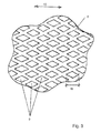
- FIG. 3 is a detail view an expanded metal layer.
- FIG. 4 shows the first step of a method according to the invention.
- FIG. 5 shows the second step of the method according to the invention.
- FIG. 6 shows the third step of the method according to the invention.
- FIG. 1 shows in a purely schematic illustration a membrane electrode assembly 1 (MEA for short).
- the membrane electrode assembly 1 comprises a membrane 2 which is provided on both sides with a catalyst layer 3 . Neighboring these catalyst layers 3 , a first gas diffusion electrode 4 and a second gas diffusion electrode 5 are provided, respectively.
- the gas diffusion electrode 4 can form the anode side, for example, and the gas diffusion electrode 5 the cathode side.
- the gas diffusion electrodes 4 , 5 are comprised of individual expanded metal layers 6 , 7 , 8 that are welded to each other, as is shown in an exemplary fashion with the aid of the gas diffusion electrode 4 in FIG. 2 .
- the gas diffusion electrode 4 in the illustrated embodiment comprises a total of six first expanded metal layers wherein expanded metal layers with differently sized meshes are provided.
- Two first expanded metal layers 6 with comparatively small mesh width, three expanded metal layers 7 with larger mesh width as well as an expanded metal layer 8 with a comparatively coarse mesh width are provided.
- the mesh width decreases from coarse to fine in the direction of arrow 11 , i.e., with reference to the illustration of FIG. 1 , in the direction toward the membrane 2 contacting the gas diffusion electrode 4 , 5 in the final mounted state.
- FIG. 3 shows a detail view of the expanded metal layer 8 .
- the expanded metal layer 8 comprises a plurality of diamond-shaped meshes 9 which each have a mesh width W.
- the length orientation 10 of the expanded metal layer 8 is oriented in the direction of the mesh width W that determines the mesh size.
- the individual expanded metal layers of the gas diffusion electrode 4 , 5 are connected to each other by welding.
- at least one of the expanded metal layers 6 , 7 and/or 8 is rotated in regard to its length orientation 10 by 90° relative to its neighboring expanded metal layer 6 , 7 or 8 , i.e., the expanded metal layers are oriented relative to each other in rotated arrangement such that the mesh width of the meshes of the associated expanded metal layers are oriented transversely, preferably rotated by 90°, relative to each other in respective neighboring layers.
- the first expanded metal layers 6 and 7 are connected to each other by means of pulsed resistance welding, namely at contact points of their facing flat sides 15 , 16 . Accordingly, a contact connection between neighboring first expanded metal layers is provided that, as a whole, can be said to be areally connected.
- the further (second) expanded metal layer 8 is not areally connected to the composite that is formed of the first expanded metal layers 6 and 7 but only spot-wise, which is achieved by spot welding.
- FIGS. 4, 5 and 6 illustrate the method according to the invention schematically.
- welding electrodes 12 of a flat (areal) areal configuration are used for welding the first expanded metal layers 6 and 7 by pulsed resistance welding.
- the expanded metal layers which are to be welded to each other are introduced into the gap between the two welding electrodes 12 .
- the two welding electrodes 12 are moved toward each other causing a compression of the first expanded metal layers 6 and 7 arranged between the welding electrodes 12 .
- the movement of the welding electrodes 12 is stopped when the first expanded metal layers 6 , 7 have been compressed by a defined force F that is predetermined, for example, by a control unit.
- the compression force F is selected in particular based on the geometric configuration and/or the material of the first expanded metal layers 6 and 7 to be connected to each other and can be adjusted as needed.
- a welding pulse is applied via the welding electrodes 12 , namely for a certain pulse duration at a defined welding energy.
- the pulse duration is preferably in the range of a few milliseconds, for example, between 5 ms and 100 ms.
- the welding energy can be, for example, between 1.4 J/mm 2 and 2.4 J/mm 2 .
- the first expanded metal layers 6 and 7 that are welded to each other form the joined composite 13 .
- the further or second expanded metal layer 8 is then applied and spot-welded thereto for which purpose a spot-welding electrode 14 is used, as shown in the illustration of FIG. 6 .
- a spot-welding electrode 14 is used, as shown in the illustration of FIG. 6 .
- the connection between the second expanded metal layer 8 and the joined composite 13 is not areally connected, but is formed by individual spot welds.
Landscapes
- Engineering & Computer Science (AREA)
- Chemical & Material Sciences (AREA)
- Mechanical Engineering (AREA)
- Electrochemistry (AREA)
- Chemical Kinetics & Catalysis (AREA)
- Materials Engineering (AREA)
- Metallurgy (AREA)
- Organic Chemistry (AREA)
- General Chemical & Material Sciences (AREA)
- Manufacturing & Machinery (AREA)
- Life Sciences & Earth Sciences (AREA)
- Sustainable Development (AREA)
- Sustainable Energy (AREA)
- Composite Materials (AREA)
- Inorganic Chemistry (AREA)
- Electrolytic Production Of Non-Metals, Compounds, Apparatuses Therefor (AREA)
- Electrodes For Compound Or Non-Metal Manufacture (AREA)
- Fuel Cell (AREA)
Applications Claiming Priority (3)
| Application Number | Priority Date | Filing Date | Title |
|---|---|---|---|
| EP14181052.3A EP2985096B1 (de) | 2014-08-14 | 2014-08-14 | Gasdiffusionselektrode |
| EP14181052 | 2014-08-14 | ||
| EP14181052.3 | 2014-08-14 |
Publications (2)
| Publication Number | Publication Date |
|---|---|
| US20160049677A1 US20160049677A1 (en) | 2016-02-18 |
| US9782853B2 true US9782853B2 (en) | 2017-10-10 |
Family
ID=51357781
Family Applications (1)
| Application Number | Title | Priority Date | Filing Date |
|---|---|---|---|
| US14/821,699 Active 2035-11-01 US9782853B2 (en) | 2014-08-14 | 2015-08-08 | Gas diffusion electrode |
Country Status (3)
| Country | Link |
|---|---|
| US (1) | US9782853B2 (de) |
| EP (1) | EP2985096B1 (de) |
| CA (1) | CA2898533C (de) |
Cited By (4)
| Publication number | Priority date | Publication date | Assignee | Title |
|---|---|---|---|---|
| US10141584B2 (en) * | 2016-06-09 | 2018-11-27 | Hyundai Motor Company | Separator of fuel cell and fuel cell having the same |
| US12297547B2 (en) | 2023-08-31 | 2025-05-13 | Dioxycle | Compressible flow distribution system for electrolyzer plates |
| WO2025214595A1 (en) * | 2024-04-10 | 2025-10-16 | Robert Bosch Gmbh | Method of producing an electrochemical cell |
| WO2025214639A1 (de) * | 2024-04-09 | 2025-10-16 | Siemens Energy Global GmbH & Co. KG | Gasdiffusionslage für eine elektrolysezelle |
Families Citing this family (22)
| Publication number | Priority date | Publication date | Assignee | Title |
|---|---|---|---|---|
| KR101896320B1 (ko) * | 2016-03-04 | 2018-09-07 | 기아자동차 주식회사 | 연료전지의 gdl 커팅시스템 |
| DE102016223781A1 (de) * | 2016-11-30 | 2018-05-30 | Robert Bosch Gmbh | Brennstoffzelle mit verbesserter Robustheit |
| JP6887100B2 (ja) * | 2016-12-26 | 2021-06-16 | パナソニックIpマネジメント株式会社 | 膜電極接合体および電気化学式水素ポンプ |
| JP2018109221A (ja) * | 2017-01-05 | 2018-07-12 | パナソニックIpマネジメント株式会社 | 電気化学式水素ポンプ |
| CN110506352B (zh) * | 2017-04-13 | 2022-06-17 | 贝卡尔特公司 | 气体扩散层 |
| CN107838635B (zh) * | 2017-10-17 | 2019-03-22 | 陕西智拓固相增材制造技术有限公司 | 托盘夹具的加工方法 |
| CN109968680B (zh) * | 2019-04-12 | 2023-09-08 | 吉林大学 | 一种基于脉冲电流的碳纤维复合材料与铝合金无铆钉铆接装置及方法 |
| WO2022061851A1 (zh) * | 2020-09-28 | 2022-03-31 | 宁德新能源科技有限公司 | 电池 |
| US20220102738A1 (en) * | 2020-09-28 | 2022-03-31 | Hyzon Motors Inc. | Non-channeled and anisotropic flow field for distribution sections in fuel cells |
| CN112838233B (zh) * | 2021-01-22 | 2023-02-28 | 中汽创智科技有限公司 | 一种燃料电池气体扩散层、电极、膜电极组件、单电池及其制备方法 |
| US11549188B2 (en) * | 2021-04-28 | 2023-01-10 | Industrial Technology Research Institute | Membrane electrode assembly and method for hydrogen evolution by electrolysis |
| DE102022102060A1 (de) | 2022-01-28 | 2023-08-03 | Melicon Gmbh | Membran-Elektroden-Vorrichtung für eine Brennstoffzelle |
| DE102022114060A1 (de) * | 2022-06-03 | 2023-12-14 | Ks Gleitlager Gmbh | Verfahren zum Herstellen einer metallischen Trägerstruktur für eine Elektrode, metallische Trägerstruktur und Elektrode |
| EP4343898A1 (de) | 2022-09-21 | 2024-03-27 | iGas energy GmbH | Kombination von poröser transportschicht und bipolarplatte für elektrochemische zellen |
| DE102022130553A1 (de) | 2022-11-18 | 2024-05-23 | Melicon Gmbh | Gasdiffusionselektrode, Membran-Elektroden-Anordnung und Elektrolysevorrichtung |
| EP4428959A1 (de) | 2023-03-08 | 2024-09-11 | Melicon GmbH | Bipolarplatten-elektrodenanordnung und verfahren |
| GB2628668A (en) * | 2023-03-31 | 2024-10-02 | Itm Power Trading Ltd | Composite sinter |
| EP4570953A1 (de) * | 2023-12-15 | 2025-06-18 | Sungrow Deutschland GmbH | Poröse transportmehrschichten |
| DE202024103377U1 (de) * | 2024-06-21 | 2025-09-25 | Melicon Gmbh | Gasdiffusionselektrode, Membran-Elektroden-Anordnung und Elektrolysevorrichtung |
| DE102024205954A1 (de) * | 2024-06-26 | 2025-12-31 | Siemens Energy Global GmbH & Co. KG | Wasserstofftechnologiegerät |
| WO2026041176A1 (de) | 2024-08-19 | 2026-02-26 | Gkn Powder Metallurgy Gmbh | Komponente für eine elektrolysezelle |
| DE102024208392A1 (de) | 2024-09-04 | 2026-03-05 | Siemens Energy Global GmbH & Co. KG | Gasdiffusionsschicht für eine Elektrolysezelle sowie Verfahren zur Herstellung einer Gasdiffusionsschicht |
Citations (8)
| Publication number | Priority date | Publication date | Assignee | Title |
|---|---|---|---|---|
| US3907513A (en) | 1974-05-30 | 1975-09-23 | Us Energy | Controlled porosity filter and uniform structure composites |
| US5804055A (en) | 1995-05-04 | 1998-09-08 | Eltech Systems Corporation | Electrode, electrochemical cell and electrochemical processes |
| US6071386A (en) | 1998-06-26 | 2000-06-06 | Siemens Aktiengesellschaft | Electrolysis apparatus |
| US20030162081A1 (en) | 2000-06-02 | 2003-08-28 | Fritz Gestermann | Dimensionally stable gas diffusion electrode |
| US20060014451A1 (en) | 2002-10-31 | 2006-01-19 | Ulrich Muller | Method for producing a porous, plate-type metallic composite |
| US20080131745A1 (en) * | 2006-12-04 | 2008-06-05 | Toyota Jidosha Kabushiki Kaisha | Fuel cells |
| US20080245662A1 (en) | 2004-05-07 | 2008-10-09 | Eilenburger Elektrolyse- Und Umwelttechnik Gmbh | Electrolytic Cell Comprising Multilayer Expanded Metal |
| US8067097B2 (en) | 2005-11-30 | 2011-11-29 | Melicon Gmbh | Woven laminate as lining for sound absorption of inlet and outlet sound absorbers and method of production of an acoustic insulation unit |
Family Cites Families (1)
| Publication number | Priority date | Publication date | Assignee | Title |
|---|---|---|---|---|
| DE19729429C1 (de) | 1997-07-09 | 1999-01-14 | Siemens Ag | Elektrolysevorrichtung |
-
2014
- 2014-08-14 EP EP14181052.3A patent/EP2985096B1/de active Active
-
2015
- 2015-07-30 CA CA2898533A patent/CA2898533C/en active Active
- 2015-08-08 US US14/821,699 patent/US9782853B2/en active Active
Patent Citations (8)
| Publication number | Priority date | Publication date | Assignee | Title |
|---|---|---|---|---|
| US3907513A (en) | 1974-05-30 | 1975-09-23 | Us Energy | Controlled porosity filter and uniform structure composites |
| US5804055A (en) | 1995-05-04 | 1998-09-08 | Eltech Systems Corporation | Electrode, electrochemical cell and electrochemical processes |
| US6071386A (en) | 1998-06-26 | 2000-06-06 | Siemens Aktiengesellschaft | Electrolysis apparatus |
| US20030162081A1 (en) | 2000-06-02 | 2003-08-28 | Fritz Gestermann | Dimensionally stable gas diffusion electrode |
| US20060014451A1 (en) | 2002-10-31 | 2006-01-19 | Ulrich Muller | Method for producing a porous, plate-type metallic composite |
| US20080245662A1 (en) | 2004-05-07 | 2008-10-09 | Eilenburger Elektrolyse- Und Umwelttechnik Gmbh | Electrolytic Cell Comprising Multilayer Expanded Metal |
| US8067097B2 (en) | 2005-11-30 | 2011-11-29 | Melicon Gmbh | Woven laminate as lining for sound absorption of inlet and outlet sound absorbers and method of production of an acoustic insulation unit |
| US20080131745A1 (en) * | 2006-12-04 | 2008-06-05 | Toyota Jidosha Kabushiki Kaisha | Fuel cells |
Cited By (4)
| Publication number | Priority date | Publication date | Assignee | Title |
|---|---|---|---|---|
| US10141584B2 (en) * | 2016-06-09 | 2018-11-27 | Hyundai Motor Company | Separator of fuel cell and fuel cell having the same |
| US12297547B2 (en) | 2023-08-31 | 2025-05-13 | Dioxycle | Compressible flow distribution system for electrolyzer plates |
| WO2025214639A1 (de) * | 2024-04-09 | 2025-10-16 | Siemens Energy Global GmbH & Co. KG | Gasdiffusionslage für eine elektrolysezelle |
| WO2025214595A1 (en) * | 2024-04-10 | 2025-10-16 | Robert Bosch Gmbh | Method of producing an electrochemical cell |
Also Published As
| Publication number | Publication date |
|---|---|
| CA2898533A1 (en) | 2016-02-14 |
| CA2898533C (en) | 2021-01-05 |
| EP2985096A1 (de) | 2016-02-17 |
| US20160049677A1 (en) | 2016-02-18 |
| EP2985096B1 (de) | 2016-11-02 |
Similar Documents
| Publication | Publication Date | Title |
|---|---|---|
| US9782853B2 (en) | Gas diffusion electrode | |
| US11289708B2 (en) | Gas diffusion layer | |
| US20050017055A1 (en) | Electrochemical fuel cell component materials and methods of bonding electrochemical fuel cell components | |
| EP1434294B1 (de) | Nachgiebiger Stromabnehmer für Anode und Kathode einer Brennstoffzelle | |
| US20190109333A1 (en) | Fuel cell single cell | |
| US20240204206A1 (en) | Electrode | |
| CN1316660C (zh) | 用于燃料电池或者电解槽的金属叠板,包括这种叠板的燃料电池或者电解槽,以及这种叠板在燃料电池或者电解槽中的应用 | |
| JP4881511B2 (ja) | 給電体 | |
| JP4305929B2 (ja) | イオン交換膜電解槽 | |
| US12195862B2 (en) | Use of a textile, zero-gap electrolytic cell and production method therefor | |
| US20220145481A1 (en) | Elastic mattress and electrolyzer | |
| JP2010065271A (ja) | 給電体、及び該給電体を備える水電解スタック、及び該水電解スタックを備える水電解装置 | |
| JP2001279479A (ja) | 給電体および電解セル | |
| JP2004315933A (ja) | 給電体および電解セル | |
| JP2024127839A (ja) | バイポーラ電極アセンブリおよび方法 | |
| US20260008102A1 (en) | Method for producing layered sheet structures from titanium or titanium alloys for use in electrodes of pem-type electrolyzers and/or fuel cells | |
| US20150104727A1 (en) | Method of forming a fuel cell sheet | |
| JP2008103142A (ja) | 燃料電池用ガス拡散層およびその製造方法ならびにこれを用いた固体高分子形燃料電池 | |
| JP5192654B2 (ja) | 燃料電池用電極の製造方法 | |
| KR20250174598A (ko) | 다공성 수송 층 | |
| EP4689233A1 (de) | Poröse transportschicht | |
| CN111162284A (zh) | 用于燃料电池中的工作材料分配的电极 | |
| CN120435589A (zh) | 用于形成电解槽的电池、包含这样的电池的电解槽、用于制造和操作电解槽的方法 | |
| JP2026513306A (ja) | 複合焼結体 | |
| JP2019192398A (ja) | 金属部品の積層接合体、および金属部品の積層接合体の製造方法 |
Legal Events
| Date | Code | Title | Description |
|---|---|---|---|
| AS | Assignment |
Owner name: MELICON GMBH, GERMANY Free format text: ASSIGNMENT OF ASSIGNORS INTEREST;ASSIGNOR:MUELLER, ULRICH;REEL/FRAME:036284/0129 Effective date: 20150721 |
|
| STCF | Information on status: patent grant |
Free format text: PATENTED CASE |
|
| MAFP | Maintenance fee payment |
Free format text: PAYMENT OF MAINTENANCE FEE, 4TH YR, SMALL ENTITY (ORIGINAL EVENT CODE: M2551); ENTITY STATUS OF PATENT OWNER: SMALL ENTITY Year of fee payment: 4 |
|
| MAFP | Maintenance fee payment |
Free format text: PAYMENT OF MAINTENANCE FEE, 8TH YR, SMALL ENTITY (ORIGINAL EVENT CODE: M2552); ENTITY STATUS OF PATENT OWNER: SMALL ENTITY Year of fee payment: 8 |