US9782831B2 - Cutting insert having structured tool flanks - Google Patents
Cutting insert having structured tool flanks Download PDFInfo
- Publication number
- US9782831B2 US9782831B2 US13/989,113 US201113989113A US9782831B2 US 9782831 B2 US9782831 B2 US 9782831B2 US 201113989113 A US201113989113 A US 201113989113A US 9782831 B2 US9782831 B2 US 9782831B2
- Authority
- US
- United States
- Prior art keywords
- cutting
- cutting insert
- edge
- cutting edge
- recess
- Prior art date
- Legal status (The legal status is an assumption and is not a legal conclusion. Google has not performed a legal analysis and makes no representation as to the accuracy of the status listed.)
- Expired - Fee Related, expires
Links
Images


Classifications
-
- B—PERFORMING OPERATIONS; TRANSPORTING
- B23—MACHINE TOOLS; METAL-WORKING NOT OTHERWISE PROVIDED FOR
- B23B—TURNING; BORING
- B23B27/00—Tools for turning or boring machines; Tools of a similar kind in general; Accessories therefor
- B23B27/22—Cutting tools with chip-breaking equipment
-
- B—PERFORMING OPERATIONS; TRANSPORTING
- B23—MACHINE TOOLS; METAL-WORKING NOT OTHERWISE PROVIDED FOR
- B23B—TURNING; BORING
- B23B27/00—Tools for turning or boring machines; Tools of a similar kind in general; Accessories therefor
- B23B27/14—Cutting tools of which the bits or tips or cutting inserts are of special material
- B23B27/141—Specially shaped plate-like cutting inserts, i.e. length greater or equal to width, width greater than or equal to thickness
- B23B27/145—Specially shaped plate-like cutting inserts, i.e. length greater or equal to width, width greater than or equal to thickness characterised by having a special shape
-
- B—PERFORMING OPERATIONS; TRANSPORTING
- B23—MACHINE TOOLS; METAL-WORKING NOT OTHERWISE PROVIDED FOR
- B23B—TURNING; BORING
- B23B2200/00—Details of cutting inserts
- B23B2200/12—Side or flank surfaces
- B23B2200/128—Side or flank surfaces with one or more grooves
-
- B—PERFORMING OPERATIONS; TRANSPORTING
- B23—MACHINE TOOLS; METAL-WORKING NOT OTHERWISE PROVIDED FOR
- B23C—MILLING
- B23C2200/00—Details of milling cutting inserts
- B23C2200/12—Side or flank surfaces
- B23C2200/128—Side or flank surfaces with one or more grooves
-
- B—PERFORMING OPERATIONS; TRANSPORTING
- B23—MACHINE TOOLS; METAL-WORKING NOT OTHERWISE PROVIDED FOR
- B23C—MILLING
- B23C5/00—Milling-cutters
- B23C5/16—Milling-cutters characterised by physical features other than shape
- B23C5/20—Milling-cutters characterised by physical features other than shape with removable cutter bits or teeth or cutting inserts
-
- Y—GENERAL TAGGING OF NEW TECHNOLOGICAL DEVELOPMENTS; GENERAL TAGGING OF CROSS-SECTIONAL TECHNOLOGIES SPANNING OVER SEVERAL SECTIONS OF THE IPC; TECHNICAL SUBJECTS COVERED BY FORMER USPC CROSS-REFERENCE ART COLLECTIONS [XRACs] AND DIGESTS
- Y10—TECHNICAL SUBJECTS COVERED BY FORMER USPC
- Y10T—TECHNICAL SUBJECTS COVERED BY FORMER US CLASSIFICATION
- Y10T407/00—Cutters, for shaping
- Y10T407/23—Cutters, for shaping including tool having plural alternatively usable cutting edges
- Y10T407/235—Cutters, for shaping including tool having plural alternatively usable cutting edges with integral chip breaker, guide or deflector
-
- Y—GENERAL TAGGING OF NEW TECHNOLOGICAL DEVELOPMENTS; GENERAL TAGGING OF CROSS-SECTIONAL TECHNOLOGIES SPANNING OVER SEVERAL SECTIONS OF THE IPC; TECHNICAL SUBJECTS COVERED BY FORMER USPC CROSS-REFERENCE ART COLLECTIONS [XRACs] AND DIGESTS
- Y10—TECHNICAL SUBJECTS COVERED BY FORMER USPC
- Y10T—TECHNICAL SUBJECTS COVERED BY FORMER US CLASSIFICATION
- Y10T407/00—Cutters, for shaping
- Y10T407/24—Cutters, for shaping with chip breaker, guide or deflector
Definitions
- the invention concerns a cutting insert with at least one structured tool flank, wherein the cutting insert comprises an upper and a lower surface and one or more edge surfaces which connect the upper surface and the lower surface together, wherein provided at the transition of at least one edge surface at least to the upper surface is at least one cutting edge, wherein the upper surface adjoining the cutting edge is in the form of a chip surface and the edge surface adjoining the cutting edge is in the form of a tool flank.
- Such a cutting insert is known for example from DE 43 36 055 A1.
- the important consideration is in particular achieving an improved cutting action and a reduction in the tool flank or relief surface wear, insofar as the tool flank or relief surface has changing relief angles along the cutting edge.
- selectively recesses or raised portions projecting from the tool flank which extend on the tool flank to relatively close to the cutting edge in order to cause the effect of the changing relief angles to be operative.
- corresponding recesses extend to the cutting edge as far as 0.2 mm, wherein raised portions preferably project to the cutting edge even as far as 0.1 mm.
- the recesses and/or raised portions are relatively short in a direction parallel to the cutting edge so that a plurality of recesses and/or raised portions alternate with interposed flat regions of the tool flank so that a change in the respective relief angle correspondingly frequently occurs along the cutting edge.
- the cutting performance of the cutting insert is intended to be smoothed by better guidance and a further reduction in vibration, wherein in particular the aim is to achieve a reduction in tool flank wear, a reduction in the tendency to chatter and a reduction in the forces normal to the cut.
- the recesses or raised portions are provided in such a way that there are locally continually changing relief angles.
- suitable cutting inserts for certain materials are limited in their application to a respective given range of advance movements and cutting depths, within which reliable chip breakage occurs, while the application in other advance and cutting depth ranges is avoided or is not recommended in particular in regard to the formation of detrimental chips.
- the recommended range of advances and cutting depths is also referred to as the chip break range.
- the object of the present invention is to provide a cutting insert in which the risk of damage to the cutting insert and/or the tool and/or the workpiece due to coiling chips is reduced and the chip break range is enlarged.
- That object is attained in that at least one recess is provided in the tool flank at a spacing from the cutting edge.
- the length of the recess or recesses is preferably at least 30% and in particular at least 40% of the length of the associated cutting edge (that is to say generally the most closely adjacent one).
- the length of those recesses is to be added along that direction, to satisfy the aforementioned condition.
- the important consideration with the present invention is that a chip which impinges on the exposed tool flank impinges as much as possible on a recess and is ‘hooked’ in that recess and as a result possibly breaks and is carried away before it passes into the above-described critical regions.
- the chip break range is effectively enlarged thereby.
- the recess therefore may not be excessively small and must also be sufficiently deep, in which case the generally flat regions of the tool flank, that are not involved by the recess, are substantially restricted to the portion directly adjoining the cutting edge.
- the recess can be in the form of a groove extending parallel to the cutting edge.
- the spacing of the recess or groove relative to the cutting edge should be at least a tenth of the minimum spacing between the upper and lower surfaces of the cutting insert, wherein that spacing can also be briefly defined as the ‘thickness’ of the cutting insert. It will be noted however that the spacing of the recess relative to the cutting edge should as far as possible also be no greater than a third of the thickness of the cutting insert. In absolute numbers the spacing of the recesses from the cutting edge is in the range of at least 0.3 to a maximum of 3 mm.
- the recesses according to the invention should be relatively abruptly set back from the tool flank, that is to say the angle between the inside surface of a recess and the immediately adjoining tool flank should be at least 45°, preferably being of the order of magnitude of 60° to 90°.
- the depth of the recesses, measured from the adjoining flat portions of the tool flank should be a minimum of 0.1 mm, preferably at least 0.3 mm. The depth required at a maximum to achieve the desired chip breakage effect is about 1 to 1.5 mm. Greater depths do not have any greater influence worth mentioning on the chip breakage behaviour, even if they would be harmless in that respect.
- the recess does not have any direct influence on chip formation. Rather, the effect of such a recess is that, in contrast to smooth tool flanks or those with less abrupt and less deep recesses, chips which are produced at the active portion of the cutting edge bend in that case (for example in the form of a so-called coiling chip) and are then incident on the tool flank, do not slide along the tool flank and in that case possibly pass into the gap between the tool flank and the workpiece, but rather become ‘hooked’ in such a recess, which very quickly leads to breakage of such a chip which can then be more easily transported away and reduces the risk of damage.
- the recesses according to the invention therefore have primarily no influence on the generation of the chips, but on the behaviour of the chips which have already been produced, in particular on chip breakage, which however should occur as quickly as possible after the chip is formed.
- a single suitably large recess can be arranged on a tool flank; however a plurality of recesses can also be arranged on the same tool flank, more specifically both in mutually juxtaposed and also mutually superposed relationship, in which case ‘mutually juxtaposed’ refers to an arrangement of a plurality of recesses in a direction parallel to the cutting edge and ‘mutually superposed’ refers to an arrangement of a plurality of recesses in a direction perpendicular to the cutting edge.
- the spacing of the recesses or grooves from the cutting edge tends to be somewhat greater than the spacing provided for another purpose in the recesses known from the state of the art and, as already mentioned, is at a minimum a tenth of the thickness of the cutting insert, preferably at least 0.3 mm or even more than 1 mm, for example 1.5 mm.
- the tool flanks are desirably also of a correspondingly symmetrical configuration and accordingly either have a plurality of recesses, of which one is associated with the cutting edge at the upper surface and the other is associated with the cutting edge at the lower surface, or however a recess which is not interrupted between the upper and lower cutting edges is of a symmetrical configuration with respect to the upper and lower cutting edges.
- the edge surfaces of the cutting insert in accordance with the present invention can be substantially flat, that is to say in particular the relief angle remains substantially constant over the length of the cutting edge, unless the tool flank were asymmetrically tilted in addition to the provision of one or more recesses, or unless it is provided for other reasons that the relief angle continuously or also discontinuously changes along the cutting edge.
- the claimed spacing of the grooves or recesses from the associated cutting edge only refers in each case to the active portion of a cutting edge or the tool flank region which directly adjoins same and which is acted upon by chips. Particularly in the case of turning, frequently only a small portion of a cutting edge adjoining a cutting corner comes into engagement with the workpiece. In such a case the recess in the tool flank does not necessarily maintain throughout a large spacing relative to the cutting edge, but in a portion which is sufficiently far away from the active portion of the cutting edge, it can also extend closer to the cutting edge or can also break through that (inactive) cutting edge region.
- the cutting insert is in the form of a double-sided reversible bit, in which the upper and lower surfaces are substantially the same and, depending on their respective orientation, alternately change their function as a chip surface or as a surface which rests on a tool seat.
- the invention can also be applied in particular to indexable, for example polygonal, cutting inserts having at least three and preferably at least four substantially flat edge surfaces which have the recesses according to the invention. Equally the invention could be applied in relation to round cutting inserts, in which case the recesses could then for example extend completely therearound or could also be grooves extending only portion-wise in the peripheral direction.
- the recesses or corresponding grooves extend over the entire length of an otherwise flat tool flank into the corner regions of adjacent edge surfaces adjoining the tool flank.
- grooves can also be interrupted and for example can comprise two groove-shaped portions which on the one hand do not extend beyond a corner to an adjacent edge surface and which on the other hand are also interrupted approximately in the centre beneath a cutting edge by a limb, the surface of which lies in the plane of the rest of the tool flank.
- recesses and in particular grooves can also be so provided that they extend beyond the corner regions of a cutting insert which is polygonal in plan view.
- the recesses or corresponding grooves can possibly be provided in relation to an indexable polygonal cutting insert and extend parallel to the cutting edge in the tool flank.
- the spacing relative to the cutting edge must be respectively sufficiently large to not adversely affect strength and stability of the cutting edge. That is required in particular when the wall of the recess, that is towards the cutting edge, is set back relatively abruptly, that is to say it extends at a relatively large angle of for example 60° or more relative to the plane of the tool flank.
- the effect of breaking coiling chips is achieved in particular when the chips impinge on a tool flank which is adjacent to or also spaced in relation to the active tool flank, that is to say the tool flank which adjoins the currently active cutting edge, this being related to the extent of such coiling chips in many situations of use.
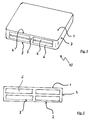
- FIG. 1 shows a perspective view of a cutting insert according to the invention in accordance with a first embodiment
- FIG. 2 shows a side view of a corresponding cutting insert
- FIGS. 3 to 9 show various variants of recesses in the edge surfaces of cutting inserts.
- FIG. 10 shows a chip break diagram
- FIG. 1 shows a perspective plan view of a substantially square cutting insert 10 having an upper surface 1 , a lower surface 2 (not visible in FIG. 1 ) and substantially flat edge surfaces 3 .
- a respective cutting edge 4 and 5 is provided at the transition between at least one of the edge surfaces 3 and the top side 1 and the underside 2 respectively.
- the tool flank or relief surface 3 which adjoins those cutting edges 4 , 5 and which extends between those cutting edges 4 , 5 has four groove-shaped, symmetrically arranged recesses which are separated from each other by a narrow limb.
- the internal spacing d of the recess from an associated cutting edge 4 or 5 is at most a third of the thickness D of the cutting insert which is substantially defined by the spacing between the cutting edges 4 , 5 or the spacing of the top side 1 from the underside 2 . If the top side 1 and the underside 2 are to be structured, that is to say are to have raised portions and/or depressions, then the spacing between the surface regions of the upper surface 1 and the lower surface 2 , that come closest to each other, can also be used as the scale for the thickness D.
- the spacing of the groove-shaped recesses 6 relative to the cutting edges 4 , 5 should however also not be any larger in each case than a quarter of that thickness D so that the recesses are sufficiently large in relation to the size or thickness of the cutting insert, in their turn.
- Cutting edges can also be provided at the transition of the other edge surfaces 3 to the upper side 1 and the lower side 2 and in that case it will be appreciated that the other edge surfaces should also have corresponding recesses 6 which however are not shown in FIG. 1 .
- FIG. 2 shows once again the tool flank 3 with four asymmetrically arranged groove-like recesses 6 .
- the respectively largest surfaces of the cutting inserts are referred to as the upper surface 1 and the lower surface 2 , in which case for comparison purposes the gross dimensions of the surface are used, that is to say without the area claimed for example by a fixing bore.
- the edge surfaces 3 are accordingly the smaller surfaces which connect the upper and lower surfaces 1 , 2 together.
- groove-like recesses 6 would not have to be separated by a central limb but that a respective recess 6 could extend in the form of a continuous groove parallel to the cutting edge 4 or the cutting edge 5 respectively. It is equally possible to provide in place of two recesses in mutually superposed relationship, that is to say a recess associated with the cutting edge 4 and one with the cutting edge 5 , a single continuous recess or groove 6 which is preferably of a symmetrical configuration with respect to the upper and lower cutting edges.
- FIGS. 3 to 9 Different configurations and arrangements of recesses 6 can be seen in FIGS. 3 to 9 which each show a different cutting insert at the top as an isometric view and at the bottom in a slightly turned side view. All cutting inserts shown in FIGS. 3 to 9 are cuboidal and are square with rounded corners in plan view.
- a groove 6 extends over the entire length of an edge surface 3 and parallel to the cutting edges 4 and 5 respectively, more specifically into the corner regions towards the adjacent edge surfaces 3 and possibly also beyond same.
- FIG. 4 which has three parallel grooves extending over the entire length of the tool flank 3 .
- FIG. 5 there are four recesses 6 which correspond to the arrangement in FIGS. 1 and 2 .
- FIG. 6 shows two recesses 6 which are displaced asymmetrically towards a cutting corner and which extend inclinedly relative to the cutting edge 4 .
- FIG. 7 shows a recess which extends beyond a corner of the cuboidal cutting insert and which extends symmetrically with respect to an angle bisector through the corner.
- FIG. 8 shows a variant with only one recess 6 which is displaced asymmetrically towards a cutting corner and
- FIG. 9 shows a cutting insert with a drop-shaped recess 6 .
- the recesses 6 may but do not necessarily have to be arranged symmetrically with respect to the cutting edge 4 or the cutting edge centre. Depending on the respective area of use involved, as shown in the embodiments by way of example, the recesses can also be displaced asymmetrically towards a corner and may also extend for example beyond a corner region, as shown by way of example in FIG. 7 . It will be appreciated that the reversible cutting bits according to the invention can also have a central fixing bore, even if that is not shown in the individual embodiments.
- FIG. 10 shows a so-called chip break diagram in which (in the field B) there is delimited with a partly broken and a continuous line an area which delimits possible parameter ranges of advance and cutting depth, at which acceptable chip breakage can be established.
- the broken line together with the continuous line shown to the right thereof delimits the parameter range possible with cutting bits which have smooth tool flanks.
- that range can be markedly enlarged in the direction of lower advances and lower cutting depths, as is indicated by the region circumscribed overall with a solid line, if the cutting bits are provided with recesses 6 in the tool flanks, as was described hereinbefore by means of examples. That enlargement of the parameter range is of significance in particular in regard to a good surface quality for the machined workpiece.
Landscapes
- Engineering & Computer Science (AREA)
- Mechanical Engineering (AREA)
- Cutting Tools, Boring Holders, And Turrets (AREA)
- Milling Processes (AREA)
- Knives (AREA)
Applications Claiming Priority (4)
| Application Number | Priority Date | Filing Date | Title |
|---|---|---|---|
| DE102010063611.8 | 2010-12-20 | ||
| DE102010063611A DE102010063611A1 (de) | 2010-12-20 | 2010-12-20 | Schneideinsatz mit strukturierten Freiflächen |
| DE102010063611 | 2010-12-20 | ||
| PCT/EP2011/073074 WO2012084718A1 (de) | 2010-12-20 | 2011-12-16 | Schneideinsatz mit strukturierten freiflächen |
Publications (2)
| Publication Number | Publication Date |
|---|---|
| US20140010608A1 US20140010608A1 (en) | 2014-01-09 |
| US9782831B2 true US9782831B2 (en) | 2017-10-10 |
Family
ID=45401062
Family Applications (1)
| Application Number | Title | Priority Date | Filing Date |
|---|---|---|---|
| US13/989,113 Expired - Fee Related US9782831B2 (en) | 2010-12-20 | 2011-12-16 | Cutting insert having structured tool flanks |
Country Status (8)
| Country | Link |
|---|---|
| US (1) | US9782831B2 (de) |
| EP (1) | EP2654993B1 (de) |
| JP (1) | JP6039573B2 (de) |
| KR (1) | KR101820557B1 (de) |
| CN (1) | CN103260801B (de) |
| DE (1) | DE102010063611A1 (de) |
| ES (1) | ES2727277T3 (de) |
| WO (1) | WO2012084718A1 (de) |
Cited By (2)
| Publication number | Priority date | Publication date | Assignee | Title |
|---|---|---|---|---|
| US20220105578A1 (en) * | 2019-01-31 | 2022-04-07 | Ab Sandvik Coromant | Round cutting insert for a milling tool |
| US20220395915A1 (en) * | 2019-10-28 | 2022-12-15 | Korloy Inc. | Cutting insert and cutting tool equipped with the same |
Families Citing this family (4)
| Publication number | Priority date | Publication date | Assignee | Title |
|---|---|---|---|---|
| JP2014076511A (ja) * | 2012-10-10 | 2014-05-01 | Sumitomo Electric Hardmetal Corp | 切削用インサート及び切削工具 |
| JP2015160266A (ja) * | 2014-02-26 | 2015-09-07 | 国立大学法人 東京大学 | 切削インサート及び刃先交換式バイト |
| US9997405B2 (en) * | 2014-09-30 | 2018-06-12 | Lam Research Corporation | Feature fill with nucleation inhibition |
| DE102016104002A1 (de) * | 2016-03-04 | 2017-09-07 | Kennametal Inc. | Schneideinsatz für einen Fräser sowie Fräser |
Citations (24)
| Publication number | Priority date | Publication date | Assignee | Title |
|---|---|---|---|---|
| GB1500732A (en) | 1975-01-16 | 1978-02-08 | Cutanit | Cutting insert of cemented carbide |
| US5382118A (en) * | 1992-09-09 | 1995-01-17 | Iscar Ltd. | Milling cutter insert |
| DE4336055A1 (de) | 1993-09-13 | 1995-03-16 | Krupp Widia Gmbh | Schneideinsatz |
| US5443334A (en) * | 1993-01-27 | 1995-08-22 | Sandvik Ab | Cutting insert with recess |
| CN1123726A (zh) | 1994-10-23 | 1996-06-05 | 伊斯卡有限公司 | 一种可互换的切削嵌入件 |
| DE19600172A1 (de) | 1996-01-04 | 1997-08-14 | Vandurit Vdh Gmbh Hartmetall U | Schneidplatte für die Metallbearbeitung, insbesondere Wendeschneidplatte |
| US5718540A (en) * | 1995-03-24 | 1998-02-17 | Iscar, Ltd. | Cutting insert having cutting edges formed with sloping lateral portions |
| DE19944406A1 (de) | 1999-09-16 | 2001-05-03 | Heller Dinklage Gmbh Geb | Bohrer, insbesondere Gesteinsbohrer |
| US6607335B2 (en) * | 1999-04-29 | 2003-08-19 | Iscar, Ltd. | Cutting tool assembly and cutting insert therefor |
| WO2004050314A2 (en) | 2002-12-04 | 2004-06-17 | Chalmers Technology Licensing Ab | Cutting tool with a cooling surface |
| WO2005065874A1 (de) | 2003-12-23 | 2005-07-21 | EMUGE-Werk Richard Glimpel GmbH & Co. KG Fabrik für Präzisionswerkzeuge | Schneidelement und werkzeug mit wenigstens einem schneidelement |
| US6929429B2 (en) * | 2002-10-10 | 2005-08-16 | Seco Tools Ab | Milling tool and cutting insert therefor |
| US20100054873A1 (en) * | 2008-08-31 | 2010-03-04 | Iscar, Ltd. | Cutting Tool and Round Double Sided Cutting Insert Therefor |
| CN101668605A (zh) | 2007-05-14 | 2010-03-10 | 钴碳化钨硬质合金公司 | 以八种方式切削的切削镶片以及用于这种切削镶片的刀夹具 |
| US20100124465A1 (en) * | 2008-11-19 | 2010-05-20 | Morrison Michael G | Double-sided ball end mill cutting insert and tool therefor |
| WO2010097797A1 (en) | 2009-02-27 | 2010-09-02 | No Screw Ltd. | Cutting tool, cutting tool holder and cutting insert therefor |
| JP2010530314A (ja) | 2007-06-21 | 2010-09-09 | セラムテック アクチエンゲゼルシャフト | ダブルポジティブな逃げ面を備えるネガティブなチップ |
| WO2010101514A1 (en) | 2009-03-06 | 2010-09-10 | Seco Tools Ab | Cutting insert with recessed insert supporting surface, and cutting tool |
| WO2010134700A2 (en) | 2009-05-19 | 2010-11-25 | Taegutec Ltd. | Double-sided cutting insert having a circular shape and cutting tool using the same |
| WO2011111197A1 (ja) | 2010-03-10 | 2011-09-15 | 株式会社タンガロイ | カッティングインサートおよび切削工具 |
| US20120195700A1 (en) * | 2011-01-31 | 2012-08-02 | Iscar Ltd. | Tangential Cutting Insert and Milling Cutter |
| US8491231B2 (en) * | 2009-06-24 | 2013-07-23 | Sandvik Intellectual Property Ab | Tool for chip removing machining as well as a solid indexable cutting insert and a solid basic body therefor |
| US8491234B2 (en) * | 2009-02-12 | 2013-07-23 | TDY Industries, LLC | Double-sided cutting inserts for high feed milling |
| US20130336732A1 (en) * | 2011-02-24 | 2013-12-19 | Mikael Jansson | Octagonal cutting insert having edge portion with variable wedge angle, and cutting tool |
-
2010
- 2010-12-20 DE DE102010063611A patent/DE102010063611A1/de not_active Withdrawn
-
2011
- 2011-12-16 EP EP11799684.3A patent/EP2654993B1/de active Active
- 2011-12-16 WO PCT/EP2011/073074 patent/WO2012084718A1/de active Application Filing
- 2011-12-16 JP JP2013543818A patent/JP6039573B2/ja not_active Expired - Fee Related
- 2011-12-16 ES ES11799684T patent/ES2727277T3/es active Active
- 2011-12-16 CN CN201180060349.9A patent/CN103260801B/zh not_active Expired - Fee Related
- 2011-12-16 KR KR1020137018169A patent/KR101820557B1/ko active IP Right Grant
- 2011-12-16 US US13/989,113 patent/US9782831B2/en not_active Expired - Fee Related
Patent Citations (33)
| Publication number | Priority date | Publication date | Assignee | Title |
|---|---|---|---|---|
| GB1500732A (en) | 1975-01-16 | 1978-02-08 | Cutanit | Cutting insert of cemented carbide |
| US5382118A (en) * | 1992-09-09 | 1995-01-17 | Iscar Ltd. | Milling cutter insert |
| US5443334A (en) * | 1993-01-27 | 1995-08-22 | Sandvik Ab | Cutting insert with recess |
| DE4336055A1 (de) | 1993-09-13 | 1995-03-16 | Krupp Widia Gmbh | Schneideinsatz |
| CN1123726A (zh) | 1994-10-23 | 1996-06-05 | 伊斯卡有限公司 | 一种可互换的切削嵌入件 |
| US5803674A (en) | 1994-10-23 | 1998-09-08 | Iscar, Ltd. | Exchangeable cutting insert |
| US5718540A (en) * | 1995-03-24 | 1998-02-17 | Iscar, Ltd. | Cutting insert having cutting edges formed with sloping lateral portions |
| DE19600172A1 (de) | 1996-01-04 | 1997-08-14 | Vandurit Vdh Gmbh Hartmetall U | Schneidplatte für die Metallbearbeitung, insbesondere Wendeschneidplatte |
| US6607335B2 (en) * | 1999-04-29 | 2003-08-19 | Iscar, Ltd. | Cutting tool assembly and cutting insert therefor |
| DE19944406A1 (de) | 1999-09-16 | 2001-05-03 | Heller Dinklage Gmbh Geb | Bohrer, insbesondere Gesteinsbohrer |
| US6929429B2 (en) * | 2002-10-10 | 2005-08-16 | Seco Tools Ab | Milling tool and cutting insert therefor |
| WO2004050314A2 (en) | 2002-12-04 | 2004-06-17 | Chalmers Technology Licensing Ab | Cutting tool with a cooling surface |
| JP2007515303A (ja) | 2003-12-23 | 2007-06-14 | ゲーエムベーハー ウント カンパニー ケージー、エミューゲ ヴェルク リチャード グリンペル | 切削要素および少なくとも一つの切削要素を備える工具 |
| DE10361450A1 (de) | 2003-12-23 | 2005-07-28 | EMUGE-Werk Richard Glimpel GmbH & Co. KG Fabrik für Präzisionswerkzeuge | Schneidelement und Werkzeug mit wenigstens einem Schneidelement |
| US20060210364A1 (en) | 2003-12-23 | 2006-09-21 | Emuge-Werk Richard Glimpel Gmbh & Co. Kg Fabrik Fur Prazisionswerkzeuge | Cutting element and tool equipped with at least one cutting element |
| CN1849192A (zh) | 2003-12-23 | 2006-10-18 | 埃莫克精密工具厂里查德格林普尔有限责任两合公司 | 切削元件和装备有至少一个切削元件的刀具 |
| WO2005065874A1 (de) | 2003-12-23 | 2005-07-21 | EMUGE-Werk Richard Glimpel GmbH & Co. KG Fabrik für Präzisionswerkzeuge | Schneidelement und werkzeug mit wenigstens einem schneidelement |
| US8454278B2 (en) | 2007-05-14 | 2013-06-04 | Kennametal Inc. | Eight-edged cutting insert, and tool holder for same |
| CN101668605A (zh) | 2007-05-14 | 2010-03-10 | 钴碳化钨硬质合金公司 | 以八种方式切削的切削镶片以及用于这种切削镶片的刀夹具 |
| JP2010530314A (ja) | 2007-06-21 | 2010-09-09 | セラムテック アクチエンゲゼルシャフト | ダブルポジティブな逃げ面を備えるネガティブなチップ |
| US8496415B2 (en) | 2007-06-21 | 2013-07-30 | Ceramtec Gmbh | Negative insert having double-positive clearance surface |
| US8206066B2 (en) * | 2008-08-31 | 2012-06-26 | Iscar, Ltd. | Cutting tool and round double sided cutting insert therefor |
| US20100054873A1 (en) * | 2008-08-31 | 2010-03-04 | Iscar, Ltd. | Cutting Tool and Round Double Sided Cutting Insert Therefor |
| US20100124465A1 (en) * | 2008-11-19 | 2010-05-20 | Morrison Michael G | Double-sided ball end mill cutting insert and tool therefor |
| US8491234B2 (en) * | 2009-02-12 | 2013-07-23 | TDY Industries, LLC | Double-sided cutting inserts for high feed milling |
| WO2010097797A1 (en) | 2009-02-27 | 2010-09-02 | No Screw Ltd. | Cutting tool, cutting tool holder and cutting insert therefor |
| WO2010101514A1 (en) | 2009-03-06 | 2010-09-10 | Seco Tools Ab | Cutting insert with recessed insert supporting surface, and cutting tool |
| WO2010134700A2 (en) | 2009-05-19 | 2010-11-25 | Taegutec Ltd. | Double-sided cutting insert having a circular shape and cutting tool using the same |
| US8491231B2 (en) * | 2009-06-24 | 2013-07-23 | Sandvik Intellectual Property Ab | Tool for chip removing machining as well as a solid indexable cutting insert and a solid basic body therefor |
| WO2011111197A1 (ja) | 2010-03-10 | 2011-09-15 | 株式会社タンガロイ | カッティングインサートおよび切削工具 |
| EP2546012A1 (de) | 2010-03-10 | 2013-01-16 | Tungaloy Corporation | Schneideeinsatz und schneidewerkzeug |
| US20120195700A1 (en) * | 2011-01-31 | 2012-08-02 | Iscar Ltd. | Tangential Cutting Insert and Milling Cutter |
| US20130336732A1 (en) * | 2011-02-24 | 2013-12-19 | Mikael Jansson | Octagonal cutting insert having edge portion with variable wedge angle, and cutting tool |
Non-Patent Citations (7)
| Title |
|---|
| German Search Report for 10 2010 063 611.8 dated Aug. 26, 2011. |
| International Preliminary Report on Patentability with Written Opinion for International Application No. PCT/EP2011/073074, dated Jun. 25, 2013. |
| International Search Report for PCT/EP2011/073074 dated Mar. 28, 2012. |
| Notice of Reasons for Rejection (with English translation) for Japanese Application No. 2013-543818 dated Jun. 7, 2016. |
| Notice of Reasons for Rejection (with English Translation) for Japanese Application No. 2013-543818, dated Oct. 13, 2015. |
| Office Action (with English translation) for Chinese Application No. 201180060349.9 dated Jun. 25, 2015. |
| Office Action (with English translation) for Chinese Application No. 201180060349.9 dated Oct. 20, 2014. |
Cited By (3)
| Publication number | Priority date | Publication date | Assignee | Title |
|---|---|---|---|---|
| US20220105578A1 (en) * | 2019-01-31 | 2022-04-07 | Ab Sandvik Coromant | Round cutting insert for a milling tool |
| US11945039B2 (en) * | 2019-01-31 | 2024-04-02 | Ab Sandvik Coromant | Round cutting insert for a milling tool |
| US20220395915A1 (en) * | 2019-10-28 | 2022-12-15 | Korloy Inc. | Cutting insert and cutting tool equipped with the same |
Also Published As
| Publication number | Publication date |
|---|---|
| CN103260801B (zh) | 2016-09-21 |
| ES2727277T3 (es) | 2019-10-15 |
| KR101820557B1 (ko) | 2018-01-19 |
| US20140010608A1 (en) | 2014-01-09 |
| EP2654993A1 (de) | 2013-10-30 |
| CN103260801A (zh) | 2013-08-21 |
| JP2014500157A (ja) | 2014-01-09 |
| KR20130132910A (ko) | 2013-12-05 |
| DE102010063611A1 (de) | 2012-06-21 |
| JP6039573B2 (ja) | 2016-12-07 |
| EP2654993B1 (de) | 2019-02-20 |
| WO2012084718A1 (de) | 2012-06-28 |
Similar Documents
| Publication | Publication Date | Title |
|---|---|---|
| US9782831B2 (en) | Cutting insert having structured tool flanks | |
| EP2403675B1 (de) | Schneideeinsatz mit eingelassener einsatzhaltefläche und schneidewerkzeug damit | |
| JP5248479B2 (ja) | 両面交換自在な切削植刃用の支持プレート | |
| JP5024483B2 (ja) | 切削インサート | |
| CN101119819B (zh) | 可转位刀片和切削刀片夹具 | |
| JP6119916B2 (ja) | 切削インサートおよび切削工具 | |
| US9370832B2 (en) | Cutting insert and cutting tool with replaceable cutting edge | |
| US8337123B2 (en) | Cutting insert, cutting tool, and cutting method using the cutting tool | |
| US9327353B2 (en) | Roughing and semi-finishing end mill having serrated and non-serrated cutting teeth | |
| US7374372B2 (en) | Indexable insert | |
| EP3006140B1 (de) | Dreheinsatz und Drehwerkzeug | |
| JP2008068345A (ja) | ラフィングエンドミルおよびラフィングエンドミル用インサート | |
| KR20140013002A (ko) | 인덱스가능한 절삭 인서트 및 인덱스가능한 절삭 인서트 홀더 | |
| KR20120134115A (ko) | 절삭 인서트 | |
| CA2697677A1 (en) | Cutting insert | |
| JPWO2015137509A1 (ja) | 切削インサート、工具ボデーおよび切削工具 | |
| JP5157660B2 (ja) | 切削インサートおよびインサート着脱式切削工具 | |
| JP2008200831A (ja) | 切削インサート | |
| US9889505B2 (en) | Mounting device for cutting tool, tool body and cutting tool | |
| JP6919824B2 (ja) | 切削インサート及び該切削インサートを用いた旋削工具 | |
| JP2007098506A (ja) | スローアウェイチップ及びスローアウェイ式エンドミル | |
| JP2006239830A (ja) | インサート着脱式エンドミル及びインサート | |
| JPWO2019082843A1 (ja) | 切削インサートおよび刃先交換式ボールエンドミル | |
| WO2015012232A1 (ja) | 切削インサートおよび切削工具 |
Legal Events
| Date | Code | Title | Description |
|---|---|---|---|
| AS | Assignment |
Owner name: WALTER AG, GERMANY Free format text: ASSIGNMENT OF ASSIGNORS INTEREST;ASSIGNOR:LENISCHENKO, STEFAN;REEL/FRAME:030864/0080 Effective date: 20130621 |
|
| STCF | Information on status: patent grant |
Free format text: PATENTED CASE |
|
| FEPP | Fee payment procedure |
Free format text: MAINTENANCE FEE REMINDER MAILED (ORIGINAL EVENT CODE: REM.); ENTITY STATUS OF PATENT OWNER: LARGE ENTITY |
|
| LAPS | Lapse for failure to pay maintenance fees |
Free format text: PATENT EXPIRED FOR FAILURE TO PAY MAINTENANCE FEES (ORIGINAL EVENT CODE: EXP.); ENTITY STATUS OF PATENT OWNER: LARGE ENTITY |
|
| STCH | Information on status: patent discontinuation |
Free format text: PATENT EXPIRED DUE TO NONPAYMENT OF MAINTENANCE FEES UNDER 37 CFR 1.362 |
|
| FP | Lapsed due to failure to pay maintenance fee |
Effective date: 20211010 |