US9768930B2 - Method for reporting channel state information, method for supporting same, and apparatus for said methods - Google Patents
Method for reporting channel state information, method for supporting same, and apparatus for said methods Download PDFInfo
- Publication number
- US9768930B2 US9768930B2 US14/373,082 US201314373082A US9768930B2 US 9768930 B2 US9768930 B2 US 9768930B2 US 201314373082 A US201314373082 A US 201314373082A US 9768930 B2 US9768930 B2 US 9768930B2
- Authority
- US
- United States
- Prior art keywords
- csi
- resource configuration
- information
- crs
- transmit
- Prior art date
- Legal status (The legal status is an assumption and is not a legal conclusion. Google has not performed a legal analysis and makes no representation as to the accuracy of the status listed.)
- Active
Links
Images


Classifications
-
- H—ELECTRICITY
- H04—ELECTRIC COMMUNICATION TECHNIQUE
- H04B—TRANSMISSION
- H04B7/00—Radio transmission systems, i.e. using radiation field
- H04B7/24—Radio transmission systems, i.e. using radiation field for communication between two or more posts
- H04B7/26—Radio transmission systems, i.e. using radiation field for communication between two or more posts at least one of which is mobile
- H04B7/2621—Radio transmission systems, i.e. using radiation field for communication between two or more posts at least one of which is mobile using frequency division multiple access [FDMA]
-
- H—ELECTRICITY
- H04—ELECTRIC COMMUNICATION TECHNIQUE
- H04L—TRANSMISSION OF DIGITAL INFORMATION, e.g. TELEGRAPHIC COMMUNICATION
- H04L5/00—Arrangements affording multiple use of the transmission path
- H04L5/003—Arrangements for allocating sub-channels of the transmission path
- H04L5/0053—Allocation of signaling, i.e. of overhead other than pilot signals
-
- H—ELECTRICITY
- H04—ELECTRIC COMMUNICATION TECHNIQUE
- H04L—TRANSMISSION OF DIGITAL INFORMATION, e.g. TELEGRAPHIC COMMUNICATION
- H04L5/00—Arrangements affording multiple use of the transmission path
- H04L5/0001—Arrangements for dividing the transmission path
- H04L5/0014—Three-dimensional division
-
- H—ELECTRICITY
- H04—ELECTRIC COMMUNICATION TECHNIQUE
- H04L—TRANSMISSION OF DIGITAL INFORMATION, e.g. TELEGRAPHIC COMMUNICATION
- H04L5/00—Arrangements affording multiple use of the transmission path
- H04L5/003—Arrangements for allocating sub-channels of the transmission path
- H04L5/0048—Allocation of pilot signals, i.e. of signals known to the receiver
- H04L5/005—Allocation of pilot signals, i.e. of signals known to the receiver of common pilots, i.e. pilots destined for multiple users or terminals
-
- H—ELECTRICITY
- H04—ELECTRIC COMMUNICATION TECHNIQUE
- H04L—TRANSMISSION OF DIGITAL INFORMATION, e.g. TELEGRAPHIC COMMUNICATION
- H04L5/00—Arrangements affording multiple use of the transmission path
- H04L5/0091—Signaling for the administration of the divided path
- H04L5/0094—Indication of how sub-channels of the path are allocated
-
- H—ELECTRICITY
- H04—ELECTRIC COMMUNICATION TECHNIQUE
- H04B—TRANSMISSION
- H04B7/00—Radio transmission systems, i.e. using radiation field
- H04B7/02—Diversity systems; Multi-antenna system, i.e. transmission or reception using multiple antennas
- H04B7/022—Site diversity; Macro-diversity
- H04B7/024—Co-operative use of antennas of several sites, e.g. in co-ordinated multipoint or co-operative multiple-input multiple-output [MIMO] systems
-
- H—ELECTRICITY
- H04—ELECTRIC COMMUNICATION TECHNIQUE
- H04B—TRANSMISSION
- H04B7/00—Radio transmission systems, i.e. using radiation field
- H04B7/02—Diversity systems; Multi-antenna system, i.e. transmission or reception using multiple antennas
- H04B7/04—Diversity systems; Multi-antenna system, i.e. transmission or reception using multiple antennas using two or more spaced independent antennas
- H04B7/06—Diversity systems; Multi-antenna system, i.e. transmission or reception using multiple antennas using two or more spaced independent antennas at the transmitting station
- H04B7/0613—Diversity systems; Multi-antenna system, i.e. transmission or reception using multiple antennas using two or more spaced independent antennas at the transmitting station using simultaneous transmission
- H04B7/0615—Diversity systems; Multi-antenna system, i.e. transmission or reception using multiple antennas using two or more spaced independent antennas at the transmitting station using simultaneous transmission of weighted versions of same signal
- H04B7/0619—Diversity systems; Multi-antenna system, i.e. transmission or reception using multiple antennas using two or more spaced independent antennas at the transmitting station using simultaneous transmission of weighted versions of same signal using feedback from receiving side
- H04B7/0621—Feedback content
- H04B7/0626—Channel coefficients, e.g. channel state information [CSI]
Definitions
- the present invention relates to a wireless communication system. Specifically, the present invention relates to a method for reporting channel state information, a method for supporting the same and an apparatus therefor.
- M2M machine-to-machine
- PCs tablet personal computers
- CA carrier aggregation
- MIMO multiple antenna
- communication environments have evolved such that the density of accessible nodes is increased in the vicinity of a user equipment (UE).
- UE user equipment
- the node includes one or more antennas and refers to a fixed point capable of transmitting/receiving radio frequency (RF) signals to/from the user equipment (UE).
- RF radio frequency
- a communication system including high-density nodes may provide a communication service of higher performance to the UE by cooperation between nodes.
- a multi-node coordinated communication scheme in which a plurality of nodes communicates with a user equipment (UE) using the same time-frequency resources has much higher data throughput than legacy communication scheme in which each node operates as an independent base station (BS) to communicate with the UE without cooperation.
- BS base station
- a multi-node system performs coordinated communication using a plurality of nodes, each of which operates as a base station or an access point, an antenna, an antenna group, a remote radio head (RRH), and a remote radio unit (RRU).
- nodes are spaced apart from each other by a predetermined distance or more in the multi-node system.
- the nodes can be managed by one or more base stations or base station controllers which control operations of the nodes or schedule data transmitted/received through the nodes.
- Each node is connected to a base station or a base station controller which manages the node through a cable or a dedicated line.
- the multi-node system can be considered as a kind of Multiple Input Multiple Output (MIMO) system since dispersed nodes can communicate with a single UE or multiple UEs by simultaneously transmitting/receiving different data streams.
- MIMO Multiple Input Multiple Output
- the multi-node system transmits signals using the dispersed nodes, a transmission area covered by each antenna is reduced compared to antennas included in the conventional centralized antenna system. Accordingly, transmit power required for each antenna to transmit a signal in the multi-node system can be reduced compared to the conventional centralized antenna system using MIMO.
- a transmission distance between an antenna and a UE is reduced to decrease in pathloss and enable rapid data transmission in the multi-node system.
- the multi-node system reduces signal loss generated during transmission since base station(s) or base station controller(s) connected to a plurality of nodes transmit/receive data in cooperation with each other.
- base station(s) or base station controller(s) connected to a plurality of nodes transmit/receive data in cooperation with each other.
- nodes spaced apart by over a predetermined distance perform coordinated communication with a UE, correlation and interference between antennas are reduced. Therefore, a high signal to interference-plus-noise ratio (SINR) can be obtained according to the multi-node coordinated communication scheme.
- SINR signal to interference-plus-noise ratio
- the multi-node system is used with or replaces the conventional centralized antenna system to become a new foundation of cellular communication in order to reduce base station cost and backhaul network maintenance cost while extending service coverage and improving channel capacity and SINR in next-generation mobile communication systems.
- An object of the present invention devised to solve the problem lies in a method for reporting or feeding back channel state information.
- Another object of the present invention is to provide a method for transmitting or receiving information necessary to report or to feed back channel state information.
- the object of the present invention can be achieved by providing a method for receiving, by user equipment (UE), a channel state information (CSI)-reference signal (RS) in a wireless communication system, comprising: receiving CSI-RS resource configuration information; and receiving the CSI-RS based on the CSI-RS resource configuration information, wherein the CSI-RS resource configuration information includes information on a cell specific-RS (CRS) related to the CSI-RS, and the UE assumes that an antenna port associated with the information on the CRS and an antenna port used to transmit the CSI-RS corresponding to the CSI-RS resource configuration information are quasi-co-located.
- CSI channel state information
- RS channel state information-reference signal
- the information on the CRS may be used to acquire a large-scale property of a radio channel from the antenna port used to transmit the CSI-RS.
- the large-scale property of the radio channel from the antenna port used to transmit the CSI-RS may be derived from a radio channel from an antenna port used to transmit the CRS.
- the information on the CRS may include identification information about the CRS.
- the UE may be configured in transmission mode 10.
- the UE may assume that an antenna port used to transmit a demodulation reference signal (DMRS) and the antenna port used to transmit the CSI-RS identified by the CSI-RS resource configuration information are quasi-co-located with respect to large-scale properties of radio channels from the antenna ports.
- DMRS demodulation reference signal
- the CSI-RS resource configuration information may be received through higher layer signaling.
- the CSI-RS and the CRS may be transmitted from different cells.
- the large-scale property of the radio channel may include at least one of delay spread, Doppler spread, Doppler shift, average gain and average delay.
- a method for a method for transmitting, by an enhanced node B (eNB), CSI-RS in a wireless communication system comprising: transmitting CSI-RS resource configuration information to a UE; and transmitting the CSI-RS based on the CSI-RS resource configuration information to the UE, wherein the CSI-RS resource configuration information includes information on a CRS related to the CSI-RS, and the UE assumes that an antenna port associated with the information on the CRS and an antenna port used to transmit the CSI-RS corresponding to the CSI-RS resource configuration information on the CSI-RS are quasi-co-located.
- eNB enhanced node B
- a user equipment configured to receive a CSI-RS in a wireless communication system, comprising: a radio frequency (RF) unit; and a processor configured to control the RF unit, wherein the processor is configured to receive CSI-RS resource configuration information and to receive the CSI-RS based on the CSI-RS resource configuration information, wherein the CSI-RS resource configuration information includes information on a CRS related to the CSI-RS, and the UE assumes that an antenna port associated with the information on the CRS and an antenna port used to transmit the CSI-RS corresponding to the CSI-RS resource configuration information are quasi-co-located.
- RF radio frequency
- the information on the CRS may be used to acquire a large-scale property of a radio channel from the antenna port used to transmit the CSI-RS.
- the large-scale property of the radio channel from the antenna port used to transmit the CSI-RS may be derived from a radio channel from an antenna port used to transmit the CRS.
- the information on the CRS may include identification information about the CRS.
- the UE may be configured in transmission mode 10.
- the UE may assume that an antenna port used to transmit a demodulation reference signal (DMRS) and the antenna port used to transmit the CSI-RS identified by the CSI-RS resource configuration information are quasi-co-located with respect to large-scale properties of radio channels from the antenna ports.
- DMRS demodulation reference signal
- the resource configuration information on the CSI-RS may be received through higher layer signaling.
- the CSI-RS and the CRS may be transmitted from different cells.
- the large-scale property of the radio channel may include at least one of delay spread, Doppler spread, Doppler shift, average gain and average delay.
- an enhanced node B configured to transmit a CSI-RS in a wireless communication system, comprising: an RF unit; and a processor configured to control the RF unit, wherein the processor is configured to transmit CSI-RS resource configuration information to a UE and to transmit the CSI-RS based on the CSI-RS resource configuration information to the UE, wherein the CSI-RS resource configuration information includes information on a CRS related to the CSI-RS, and the UE assumes that an antenna port associated with the information on the CRS and an antenna port used to transmit the CSI-RS corresponding to the CSI-RS resource configuration information are quasi-co-located.
- eNB enhanced node B
- processing load or complexity of user equipment can be reduced when channel state information is reported.
- FIG. 1 illustrates an exemplary radio frame structure used in a wireless communication system
- FIG. 2 illustrates an exemplary downlink/uplink (DL/UL) slot structure in a wireless communication system
- FIG. 3 illustrates a downlink subframe structure used in 3GPP LTE(-A);
- FIG. 4 illustrates an exemplary uplink subframe structure used in 3GPP LTE(-A);
- FIG. 5 illustrates cell specific reference signal mapping patterns according to antenna ports
- FIG. 6 illustrates demodulation reference signal mapping patterns according to antenna ports
- FIG. 7 illustrates channel state information reference signal mapping patterns according to antenna ports
- FIG. 8 illustrates an exemplary multi-point transmission/reception operation
- FIG. 9 is a block diagram of components of a transmitter and a receiver for implementing the present invention.
- technique, device, system which will be described hereinafter, may be applied to various wireless multiplexing access systems.
- 3GPP LTE(-A) 3GPP LTE(-A)
- technical features of the present invention are limited to the 3GPP LTE(-A).
- the following description will be made based on a mobile communication system corresponding to a 3GPP LTE(-A) system, the following description may be applied to other random mobile communication system except matters specific to the 3GPP LTE(-A).
- a user equipment is fixed or mobile.
- the UE is a device that transmits and receives user data and/or control information by communicating with a base station (BS).
- BS base station
- the term ‘UE’ may be replaced with ‘terminal equipment’, ‘Mobile Station (MS)’, ‘Mobile Terminal (MT)’, ‘User Terminal (UT)’, ‘Subscriber Station (SS)’, ‘wireless device’, ‘Personal Digital Assistant (PDA)’, ‘wireless modem’, ‘handheld device’, etc.
- a BS is typically a fixed station that communicates with a UE and/or another BS. The BS exchanges data and control information with a UE and another BS.
- BS may be replaced with ‘Advanced Base Station (ABS)’, ‘Node B’, ‘evolved-Node B (eNB)’, ‘Base Transceiver System (BTS)’, ‘Access Point (AP)’, ‘Processing Server (PS)’, etc.
- ABS Advanced Base Station
- eNB evolved-Node B
- BTS Base Transceiver System
- AP Access Point
- PS Processing Server
- PDCCH Physical Downlink Control Channel
- PCFICH Physical Control Format Indicator Channel
- PHICH Physical Hybrid automatic repeat request Indicator Channel
- PDSCH Physical Downlink Shared Channel
- PUCCH Physical Uplink Control Channel
- PUSCH Physical Uplink Shared Channel
- PRACH Physical Random Access Channel
- a time-frequency resource or a resource element (RE) which is allocated to or belongs to PDCCH/PCFICH/PHICH/PDSCH/PUCCH/PUSCH/PRACH, is referred to as a PDCCH/PCFICH/PHICH/PDSCH/PUCCH/PUSCH/PRACH RE or PDCCH/PCFICH/PHICH/PDSCH/PUCCH/PUSCH/PRACH resource.
- transmission of PUCCH/PUSCH/PRACH by a UE is equivalent to transmission of uplink control information/uplink data/random access signal through or on PUCCH/PUSCH/PRACH.
- transmission of PDCCH/PCFICH/PHICH/PDSCH by an eNB is equivalent to transmission of downlink data/control information through or on PDCCH/PCFICH/PHICH/PDSCH.
- Cell-specific Reference Signal (CRS)/Demodulation Reference Signal (DMRS)/Channel State Information Reference Signal (CSI-RS) time-frequency resources respectively mean REs that may be allocated or used for CRS/DMRS/CSI-RS, or time-frequency resources (or REs) carrying CRS/DMRS/CSI-RS.
- subcarriers that include CRS/DMRS/CSI-RS RE may be referred to as CRS/DMRS/CSI-RS subcarriers
- OFDM symbols that include CRS/DMRS/CSI-RS RE may be referred to as CRS/DMRS/CSI-RS symbols.
- SRS time-frequency resources may mean time-frequency resources (or REs) transmitted from the user equipment to the base station to allow the base station to carry a sounding reference signal (SRS) used for measurement of an uplink channel status formed between the user equipment and the base station.
- the reference signal means a signal of a special waveform previously defined and known well by the user equipment and the base station, and may be referred to as a pilot.
- a cell refers to a specific geographical area in which one or more nodes provide communication services. Accordingly, communication with a specific cell may mean communication with an eNB or a node providing communication services to the specific cell.
- a downlink/uplink signal of a specific cell refers to a downlink/uplink signal from/to an eNB or a node providing communication services to the specific cell.
- a cell providing uplink/downlink communication services to a UE is called a serving cell.
- channel status/quality of a specific cell refers to channel status/quality of a channel or a communication link generated between an eNB or a node providing communication services to the specific cell and a UE.
- FIG. 1 illustrates an exemplary radio frame structure used in a wireless communication system.
- FIG. 1( a ) illustrates a frame structure for frequency division duplex (FDD) used in 3GPP LTE/LTE-A and
- FIG. 1( b ) illustrates a frame structure for time division duplex (TDD) used in 3GPP LTE/LTE-A.
- FDD frequency division duplex
- TDD time division duplex
- a radio frame used in 3GPP LTE/LTE-A has a length of 10 ms (307200 Ts) and includes 10 subframes in equal size.
- the 10 subframes in the radio frame may be numbered.
- Each subframe has a length of 1 ms and includes two slots.
- 20 slots in the radio frame can be sequentially numbered from 0 to 19.
- Each slot has a length of 0.5 ms.
- a time for transmitting a subframe is defined as a transmission time interval (TTI).
- Time resources can be discriminated by a radio frame number (or radio frame index), subframe number (or subframe index) and a slot number (or slot index).
- the radio frame can be configured differently according to duplex mode. Downlink transmission is discriminated from uplink transmission by frequency in FDD mode, and thus the radio frame includes only one of a downlink subframe and an uplink subframe in a specific frequency band. In TDD mode, downlink transmission is discriminated from uplink transmission by time, and thus the radio frame includes both a downlink subframe and an uplink subframe in a specific frequency band.
- Table 1 shows DL-UL configurations of subframes in a radio frame in the TDD mode.
- D denotes a downlink subframe
- U denotes an uplink subframe
- S denotes a special subframe.
- the special subframe includes three fields of DwPTS (Downlink Pilot TimeSlot), GP (Guard Period), and UpPTS (Uplink Pilot TimeSlot).
- DwPTS is a period reserved for downlink transmission
- UpPTS is a period reserved for uplink transmission.
- FIG. 2 illustrates an exemplary downlink/uplink slot structure in a wireless communication system. Particularly, FIG. 2 illustrates a resource grid structure in 3GPP LTE/LTE-A. A resource grid is present per antenna port.
- a slot includes a plurality of OFDM (Orthogonal Frequency Division Multiplexing) symbols in the time domain and a plurality of resource blocks (RBs) in the frequency domain.
- An OFDM symbol may refer to a symbol period.
- a signal transmitted in each slot may be represented by a resource grid composed of N RB DL/UL *N sc RB subcarriers and N symb DL/UL OFDM symbols.
- N RB DL denotes the number of RBs in a downlink slot
- N RB UL denotes the number of RBs in an uplink slot.
- N RB DL and N RB UL respectively depend on a DL transmission bandwidth and a UL transmission bandwidth.
- N symb DL denotes the number of OFDM symbols in the downlink slot and N symb UL denotes the number of OFDM symbols in the uplink slot.
- N sc RB denotes the number of subcarriers constructing one RB.
- An OFDM symbol may be called an SC-FDM (Single Carrier Frequency Division Multiplexing) symbol according to multiple access scheme.
- the number of OFDM symbols included in a slot may depend on a channel bandwidth and the length of a cyclic prefix (CP).
- CP cyclic prefix
- a slot includes 7 OFDM symbols in the case of normal CP and 6 OFDM symbols in the case of extended CP.
- FIG. 2 illustrates a subframe in which a slot includes 7 OFDM symbols for convenience, embodiments of the present invention can be equally applied to subframes having different numbers of OFDM symbols.
- each OFDM symbol includes N RB DL/UL *N sc RB subcarriers in the frequency domain.
- Subcarrier types can be classified into a data subcarrier for data transmission, a reference signal subcarrier for reference signal transmission, and null subcarriers for a guard band and a direct current (DC) component.
- the null subcarrier for a DC component is a subcarrier remaining unused and is mapped to a carrier frequency (ID) during OFDM signal generation or frequency up-conversion.
- the carrier frequency is also called a center frequency.
- An RB is defined by N symb DL/UL (e.g. 7) consecutive OFDM symbols in the time domain and N sc RB (e.g. 12) consecutive subcarriers in the frequency domain.
- N symb DL/UL e.g. 7
- N sc RB e.g. 12
- a resource composed by an OFDM symbol and a subcarrier is called a resource element (RE) or a tone.
- an RB is composed of N symb DL/UL *N sc RB REs.
- Each RE in a resource grid can be uniquely defined by an index pair (k, 1) in a slot.
- k is an index in the range of 0 to N symb DL/UL *N sc RB ⁇ 1 in the frequency domain
- 1 is an index in the range of 0 to N symb DL/UL ⁇ 1.
- a physical resource block (PRB) pair Two RBs that occupy N sc RB consecutive subcarriers in a subframe and respectively disposed in two slots of the subframe are called a physical resource block (PRB) pair. Two RBs constituting a PRB pair have the same PRB number (or PRB index).
- a virtual resource block (VRB) is a logical resource allocation unit for resource allocation. The VRB has the same size as that of the PRB.
- the VRB may be divided into a localized VRB and a distributed VRB depending on a mapping scheme of VRB into PRB.
- N VRB DL N RB DL is obtained. Accordingly, according to the localized mapping scheme, the VRBs having the same VRB number are mapped into the PRBs having the same PRB number at the first slot and the second slot. On the other hand, the distributed VRBs are mapped into the PRBs through interleaving. Accordingly, the VRBs having the same VRB number may be mapped into the PRBs having different PRB numbers at the first slot and the second slot. Two PRBs, which are respectively located at two slots of the subframe and have the same VRB number, will be referred to as a pair of VRBs.
- FIG. 3 illustrates a downlink (DL) subframe structure used in 3GPP LTE/LTE-A.
- a DL subframe is divided into a control region and a data region.
- a maximum of three (four) OFDM symbols located in a front portion of a first slot within a subframe correspond to the control region to which a control channel is allocated.
- a resource region available for PDCCH transmission in the DL subframe is referred to as a PDCCH region hereinafter.
- the remaining OFDM symbols correspond to the data region to which a physical downlink shared chancel (PDSCH) is allocated.
- PDSCH physical downlink shared chancel
- a resource region available for PDSCH transmission in the DL subframe is referred to as a PDSCH region hereinafter.
- Examples of downlink control channels used in 3GPP LTE include a physical control format indicator channel (PCFICH), a physical downlink control channel (PDCCH), a physical hybrid ARQ indicator channel (PHICH), etc.
- the PCFICH is transmitted at a first OFDM symbol of a subframe and carries information regarding the number of OFDM symbols used for transmission of control channels within the subframe.
- the PHICH is a response of uplink transmission and carries an HARQ acknowledgment (ACK)/negative acknowledgment (NACK) signal.
- ACK HARQ acknowledgment
- NACK negative acknowledgment
- the DCI contains resource allocation information and control information for a UE or a UE group.
- the DCI includes a transport format and resource allocation information of a downlink shared channel (DL-SCH), a transport format and resource allocation information of an uplink shared channel (UL-SCH), paging information of a paging channel (PCH), system information on the DL-SCH, information about resource allocation of an upper layer control message such as a random access response transmitted on the PDSCH, a transmit control command set with respect to individual UEs in a UE group, a transmit power control command, information on activation of a voice over IP (VoIP), downlink assignment index (DAI), etc.
- DL-SCH downlink shared channel
- UL-SCH uplink shared channel
- PCH paging information of a paging channel
- system information on the DL-SCH information about resource allocation of an upper layer control message such as a random access response transmitted on the PDSCH
- the transport format and resource allocation information of the DL-SCH are also called DL scheduling information or a DL grant and the transport format and resource allocation information of the UL-SCH are also called UL scheduling information or a UL grant.
- the size and purpose of DCI carried on a PDCCH depend on DCI format and the size thereof may be varied according to coding rate.
- a plurality of PDCCHs may be transmitted in a PDCCH region of a DL subframe.
- a UE may monitor a plurality of PDCCHs.
- a BS decides a DCI format according to DCI to be transmitted to a UE and attaches a cyclic redundancy check (CRC) to the DCI.
- the CRC is masked with an identifier (e.g., a Radio Network Temporary Identifier (RNTI)) according to an owner or usage of the PDCCH.
- RNTI Radio Network Temporary Identifier
- a paging indicator identifier may be masked to the CRC.
- P-RNTI paging indicator identifier
- SIB system information block
- SI-RNTI system information RNTI
- RA-RNTI random access-RNTI
- a PDCCH is transmitted on one control channel element (CCE) or an aggregate of a plurality of consecutive CCEs.
- the CCE is a logical allocation unit used to provide a coding rate to a PDCCH based on a radio channel state.
- the CCE corresponds to a plurality of resource element groups (REGs). For example, one CCE corresponds to nine REGs and one REG corresponds to four REs.
- Four QPSK symbols are mapped to each REG.
- An RE occupied by an RS is not included in an REG. Accordingly, the number of REGs within a given OFDM symbol is changed according to presence/absence of an RS.
- the REG concept is also used for other DL control channels (that is, a PCFICH and a PHICH).
- a DCI format and the number of DCI bits are determined according to the number of CCEs.
- CCEs are numbered and consecutively used and, in order to simplify decoding, a PDCCH having a format composed of n CCEs may start from only a CCE having a number corresponding to a multiple of n.
- the number of CCEs used to transmit a specific PDCCH is determined by a BS according to a channel state. For example, in case of a PDCCH for a UE having a good DL channel (e.g., a UE adjacent to a BS), one CCE may be sufficient. However, in case of a PDCCH for a UE having a bad channel (e.g., a UE located at a cell edge), 8 CCEs are required to obtain sufficient robustness.
- FIG. 4 is a diagram showing an example of an uplink subframe structure used in a 3GPP LTE(-A) system.
- a UL subframe may be divided into a control region and a data region in a frequency domain.
- One or several physical uplink control channels may be allocated to the control region in order to carry uplink control information (UCI).
- One or several physical uplink shared channels (PUSCHs) may be allocated to the data region of the UL subframe in order to carry user data.
- the control region and the data region in the UL subframe are also referred to as a PUCCH region and a PUSCH region, respectively.
- a sounding reference signal (SRS) may be allocated to the data region.
- the SRS is transmitted on a last OFDM symbol of a UL subframe in a time domain and is transmitted on a data transmission band, that is, a data region, of the UL subframe.
- SRSs of several UEs, which are transmitted/received on the last OFDM symbol of the same subframe, are distinguished according to frequency location/sequence.
- a PUCCH and a PUSCH may not be simultaneously transmitted on one carrier.
- support of simultaneous transmission of a PUCCH and a PUSCH may be indicated by a higher layer.
- a UL subframe subcarriers distant from a direct current (DC) subcarrier are used as the control region.
- DC subcarrier is a component which is not used to transmit a signal and is mapped to a carrier frequency f0 in a frequency up-conversion process.
- a PUCCH for one UE is allocated to an RB pair belonging to resources operating in one carrier frequency and RBs belonging to the RB pair occupy different subcarriers in two slots.
- the allocated PUCCH is expressed by frequency hopping of the RB pair allocated to the PUCCH at a slot boundary. If frequency hopping is not applied, the RB pair occupies the same subcarrier.
- the size and usage of UCI carried by one PUCCH may be changed according to PUCCH format and the size of the UCI may be changed according to a coding rate.
- PUCCH format For example, the following PUCCH format may be defined.
- N/A N/A SR (Scheduling Request) 1a BPSK 1 ACK/NACK or One SR + ACK/NACK codeword 1b QPSK 2 ACK/NACK or Two SR + ACK/NACK codeword 2 QPSK 20 CQI/PMI/RI Joint coding ACK/NACK (extended CP) 2a QPSK + BPSK 21 CQI/PMI/RI + Normal CP ACK/NACK only 2b QPSK + QPSK 22 CQI/PMI/RI + Normal CP ACK/NACK only 3 QPSK 48 ACK/NACK or SR + ACK/NACK or CQI/PMI/RI + ACK/NACK
- PUCCH formats 1/1a/1b are used to transmit ACK/NACK information
- PUCCH format 2/2a/2b are used to carry CSI such as CQI/PMI/RI
- PUCCH format 3 is used to transmit ACK/NACK information.
- signal distortion may occur during transmission since the packet is transmitted through a radio channel.
- the distorted signal needs to be corrected using channel information.
- a signal known to both a transmitter and the receiver is transmitted and channel information is detected with a degree of distortion of the signal when the signal is received through a channel. This signal is called a pilot signal or a reference signal.
- the receiver can receive a correct signal only when the receiver is aware of a channel state between each transmit antenna and each receive antenna. Accordingly, a reference signal needs to be provided per transmit antenna, more specifically, per antenna port.
- Reference signals can be classified into an uplink reference signal and a downlink reference signal.
- the uplink reference signal includes:
- DMRS demodulation reference signal
- a sounding reference signal used for an eNB to measure uplink channel quality at a frequency of a different network.
- the downlink reference signal includes:
- CRS cell-specific reference signal
- CSI-RS channel state information reference signal
- MBSFN multimedia broadcast single frequency network
- a positioning reference signal used to estimate geographic position information of a UE.
- Reference signals can be classified into a reference signal for channel information acquisition and a reference signal for data demodulation.
- the former needs to be transmitted in a wide band as it is used for a UE to acquire channel information on downlink transmission and received by a UE even if the UE does not receive downlink data in a specific subframe.
- This reference signal is used even in a handover situation.
- the latter is transmitted along with a corresponding resource by an eNB when the eNB transmits a downlink signal and is used for a UE to demodulate data through channel measurement.
- This reference signal needs to be transmitted in a region in which data is transmitted.
- FIG. 5 illustrates cell specific reference signal (CRS) mapping patterns according to antenna ports.
- the CRS is used for obtaining channel information and demodulating data
- a UE-specific reference signal is used for demodulating data.
- the CRS is transmitted for wideband in every subframe, and the reference signal for up to four (4) antenna ports is transmitted according to the number of the transmission antennas of the eNB.
- the CRS for #0 and #1 antenna ports is transmitted and if the number of the transmission antennas of the eNB is four, the CRS for #0 to #3 antenna ports is transmitted.
- FIG. 6 illustrates demodulation reference signal mapping patterns according to antenna ports.
- a DMRS is a reference signal defined for a UE to perform channel estimation with respect to a PDSCH.
- the DMRS can be used in transmission modes 7, 8 and 9.
- the DMRS was initially defined for single layer transmission of antenna port #5 and then extended for spatial multiplexing of a maximum of 8 layers.
- the DMRS which is also called a UE specific reference signal, is transmitted for a specific UE only and thus can be transmitted in an RB through which a PDSCH for the specific UE is transmitted.
- FIG. 6 illustrates mapping of the DMRS to a resource grid in a subframe with respect to antenna ports 7 to 10 in the normal CP case.
- r(m) denotes the reference signal sequence
- c(i) denotes a pseudo random sequence
- N RB max,DL denotes a maximum number of RBs of a downlink bandwidth.
- Equation 2 when the reference signal sequence is mapped to complex-valued modulation symbols, an orthogonal sequence w p (i) is applied according to antenna port, as shown in Table 3.
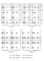
- FIG. 7 illustrates CSI-RS mapping patterns according to antenna ports.
- An antenna port for CSI-RS transmission is referred to as a CSI-RS port and positions of resources in a predetermined resource region, in which CSI-RSs are transmitted through CSI-RS ports corresponding thereto, are referred to as a CSI-RS pattern or CSI-RS resource configuration.
- a time-frequency resource to/through which a CSI-RS is allocated/transmitted is referred to as a CSI-RS resource.
- a resource element (RE) used for CSI-RS transmission is referred to as a CSI-RS RE.
- RE resource element
- the CSI-RS While the position of an RE through which a CRS is transmitted per antenna port is fixed, the CSI-RS has a maximum of 32 different configurations in order to reduce inter-cell interference (ICI) in a multi-cell environment including a heterogeneous network environment.
- a CSI-RS configuration depends on the number of antenna ports in a cell and CSI-RS configurations are set such that neighboring cells have different configurations.
- Tables 4 and 5 show CSI-RS configurations that can be used in a frame structure (referred to as FS-1 hereinafter) for FDD (frequency division duplex) and a frame structure (referred to as FS-2 hereinafter) for TDD (time division duplex). Particularly, Table 4 shows CSI-RS configurations in a subframe having the normal CP and Table 5 shows CSI-RS configurations in a subframe having the extended CP.
- FS-1 frame structure
- FS-2 time division duplex
- a time-frequency resource used by each CSI-RS port to transmit a corresponding CSI-RS can be determined. That is, a CSI-RS sequence may be mapped to complex-valued modulation symbols used as reference symbols for CSI-RS port p in slot n s in a subframe (CSI-RS subframe) configured for CSI-RS transmission according to the following equation.
- a k,l (p) w l′′ ⁇ r l,n s ( m ′′) [Equation 3]
- Equation 3 a resource index pair (k, l) (k being a subcarrier index and l being an OFDM symbol index in a subframe) used for CSI-RS port p for CSI-RS transmission can be determined according to the following equation.
- FIG. 7 illustrates CSI-RS configurations. Particularly, FIG. 7 illustrates CSI-RS configurations according to Equation 3 and Table 4 and shows positions of resources occupied by CSI-RSs in one RB pair in each CSI-RS configuration.
- FIG. 7( a ) shows 20 CSI-RS configurations available for CSI-RS transmission through 2 CSI-RS ports
- FIG. 7( b ) shows 10 CSI-RS configurations available for CSI-RS transmission through 4 CSI-RS ports
- FIG. 7( c ) shows 5 CSI-RS configurations available for CSI-RS transmission through 8 CSI-RS ports.
- CSI-RS configurations defined on the basis of the number of CSI-RS ports may be numbered.
- CSI-RS transmission is performed in a radio resource corresponding to one of the 20 CSI-RS configurations, shown in FIG. 7( a ) , through the 2 CSI-RS ports.
- 4 CSI-RS ports are set for a specific cell, CSI-RSs are transmitted in resources corresponding to CSI-RS configurations for the specific cell from among the 10 CSI-RS configurations, shown in FIG. 7( b ) , through the 4 CSI-RS ports.
- CSI-RSs are transmitted in resources corresponding to CSI-RS configurations for the specific cell from among the 5 CSI-RS configurations, shown in FIG. 7( c ) , through the 8 CSI-RS ports.
- CSI-RS configurations shown in Tables 4 and 5 have a nested property.
- the nested property means that a CSI-RS configuration for a large number of CSI-RS ports becomes a super set of a CSI-RS configuration for a small number of CSI-RS ports.
- REs corresponding to CSI-RS configuration 0 with respect to 4 CSI-RS ports are included in resources corresponding to CSI-RS configuration 0 with respect to 8 CSI-RS ports.
- a plurality of CSI-RSs may be used in a predetermined cell.
- a non-zero power CSI-RS only a CSI-RS with respect to one CSI-RS configuration is transmitted.
- a zero power CSI-RS a CSI-RS with respect to a plurality of CSI-RS configurations may be transmitted.
- a UE assumes zero transmission power for resources other than resources that need to be assumed to correspond to non-zero power CSI-RSs, from among resources corresponding to zero power CSI-RSs.
- a CSI-RS is not transmitted in a special subframe in which downlink transmission and uplink transmission coexist, a subframe in which a paging message is transmitted and a subframe in which transmission of a synchronization signal, a physical broadcast channel (PBCH) or system information block type 1 (SIB1) collide with a CSI-RS, and the UE assumes that a CSI-RS is not transmitted in these subframes.
- a time-frequency resource used for a CSI-RS port to transmit the corresponding CSI-RS is not used for PDSCH transmission through any antenna port and is not used for CSI-RS transmission through an antenna port other than the corresponding CSI-RS port.
- a CSI-RS is configured to be transmitted at a predetermined transmission interval corresponding to a plurality of subframes rather than being configured to be transmitted per subframe. In this case, CSI-RS transmission overhead can be remarkably reduced compared to a case in which the CSI-RS is transmitted per subframe.
- a subframe configured for CSI-RS transmission is referred to as a CSI-RS subframe.
- a subframe configured for CSI-RS transmission may be defined by CSI-RS transmission periodicity and subframe offset.
- the CSI-RS transmission periodicity and subframe offset are referred to as a CSI-RS subframe configuration. Table 6 shows CSI-RS transmission periodicity T CSI-RS and subframe offset ⁇ CSI-RS .
- CSI-RS subframe CSI-RS configuration CSI-RS periodicity subframe offset I CSI-RS T CSI-RS (subframes) ⁇ CSI-RS (subframes) I CSI-RS ⁇ 4 5 I CSI-RS 5 ⁇ I CSI-RS ⁇ 14 10 I CSI-RS-5 15 ⁇ I CSI-RS ⁇ 34 20 I CSI-RS-15 35 ⁇ I CSI-RS ⁇ 74 40 I CSI-RS-35 75 ⁇ I CSI-RS ⁇ 154 80 I CSI-RS-75
- I CSI-RS specifies CSI-RS transmission periodicity and subframe offset.
- the BS may determine or adjust I CSI-RS and transmit I CSI-RS to UEs within the coverage of the corresponding cell.
- a UE may be aware of a CSI-RS subframe in which a CSI-RS of the cell (referred to as a serving cell, hereinafter) that provides communication services to the UE is transmitted on the basis of I CSI-RS .
- n f denotes a system frame number and n s represents a slot number of a radio frame.
- I CSI-RS when I CSI-RS is greater than 5 and less than 14, a CSI-RS is transmitted every 10 subframes, starting from a subframe corresponding to a subframe number I CSI-RS ⁇ 5.
- the BS may notify the UE of the following parameters through higher layer signaling (e.g. medium access control (MAC) signaling or radio resource control (RRC) signaling).
- higher layer signaling e.g. medium access control (MAC) signaling or radio resource control (RRC) signaling.
- MAC medium access control
- RRC radio resource control
- the BS may notify the UE of a CSI-RS configuration transmitted with zero power and a subframe configuration for transmission of a zero power CSI-RS as necessary.
- the CSI-RS configurations of Tables 5 and 6 may be used as the zero power CSI-RS configuration and the CSI-RS subframe configuration of Table 6 may be used as the subframe configuration for transmission of the zero power CSI-RS.
- FIG. 8 illustrates a wireless communication system in which a CoMP set provides a joint transmission (JT) service to a UE. That is, the UE is set to transmission mode 10.
- Downlink operations with respect to the CoMP set include not only JT but also dynamic cell selection (DCS) configured to transmit a downlink signal from a cell (or a transmission point, for example, a BS or eNB) to a UE at one timing and coordinated scheduling/beamforming (CS/CB) configured to perform scheduling or beamforming to minimize interference applied by a UE to a plurality of cells belonging to the CoMP set JT.
- DCS dynamic cell selection
- CS/CB coordinated scheduling/beamforming
- the UE receives data from all transmission points (TPs) belonging to the CoMP set, for example, TP 1 and TP 2 and may transmit channel state information about all TPs belonging to the CoMP set.
- TPs transmission points
- RSs may be transmitted to the UE from a plurality of TPs in the CoMP set. If characteristics for channel estimation with respect to different RS ports of different TPs can be shared, then reception processing load and complexity of the UE may be reduced. In addition, if characteristics for channel estimation with respect to different RS ports of the same TP can be shared by the RS ports, then reception processing load and complexity of the UE may be decreased. Accordingly, a description will be given of a method of sharing characteristics for channel estimation between RS ports.
- quadrature co-located With regard to two antenna ports, for example, if a large-scale property of a radio channel on which a symbol is transmitted through one of the antenna ports can be inferred from a radio channel on which a symbol is transmitted through the other antenna port, then the two antenna ports can be considered to be quasi-co-located.
- the large-scale property includes at least one of delay spread, Doppler spread, Doppler shift, average gain and average delay.
- QCL quadrature co-located
- the large-scale property of a radio channel from one antenna port corresponds to the large-scale property of a radio channel from the other antenna port.
- the large-scale property of a radio channel from one antenna port may be replaced by the large-scale property of a radio channel from the other antenna port.
- the UE cannot assume the same large-scale property for radio channels from non-QCL antenna ports.
- the UE needs to perform independent processing per non-QCL antenna port for timing acquisition and tracking, frequency offset estimation and compensation, delay estimation and Doppler estimation, etc.
- the UE can perform the following operations.
- the UE Upon reception of a specific DMRS-based DL-related DCI format through a control channel (PDCCH or ePDCCH), the UE performs channel estimation with respect to a corresponding PDSCH through a DMRS sequence and then performs data demodulation.
- a control channel PDCCH or ePDCCH
- the UE may apply an estimate of the large-scale property of a radio channel, which has been estimated from the CRS ports, to channel estimation through the DMRS ports, thereby improving performance of a processor of a DMRS-based receiver.
- DMRS ports a configuration of antenna ports
- CRS ports a configuration of antenna ports
- the CRS is a reference signal that is broadcast with high density per subframe and over the entire band, as described above, the estimate of the large-scale property can be acquired from the CRS more stably.
- the DMRS is UE-specifically transmitted for a specific scheduled RB and a precoding matrix used by an eNB for transmission may be changed per PRG, and thus a valid channel received by the UE may be changed per PRG. Accordingly, performance deterioration may occur when the DMRS is used to estimate the large-scale property of a radio channel over a wide band even if a plurality of PRGs is scheduled for the UE.
- the CSI-RS has a transmission period of several to ten ms and is transmitted with as low density as 1 RE (2 REs when CDM is applied) per antenna port per RB. Thus, performance deterioration may occur when the CSI-RS is used to estimate the large-scale property of the radio channel.
- QCL assumption between antenna ports may be used for reception of downlink reference signals, channel estimation, channel state reporting, etc.
- Embodiments of the present invention provide a method for signaling, by an eNB, information on QCL assumption among downlink RSs such as DMRS, CRS, CSI-RS, etc., that is, information indicating QCL between at least two antenna ports to a UE, thereby improving CSI feedback performance of the UE and receiver processing performance.
- the UE is preferably set or operates in transmission mode 10.
- QCL assumption between different RS ports may be indicated through a CSI-RS resource configuration according to an embodiment of the present invention.
- QCL assumption between CSI-RS ports and CRS ports can be indicated.
- the UE may receive information indicating whether QCL can be assumed between each CSI-RS port and a specific RS port per CSI-RS resource configuration.
- the UE calculates channel state information (CSI) to be reported during CSI reporting with respect to each CSI-RS resource configuration, for example, CQI, RI, PMI, etc. on the basis of QCL or non-QCL (NQCL) assumption.
- CSI channel state information
- a CSI-RS resource configuration used in an embodiment of the present invention may include the following parameters or information.
- the UE may receive information indicating whether QCL with respect to CRS ports from a specific cell can be assumed per CSI-RS resource configuration. Then, the UE calculates CQI, RI, PMI, etc. to be reported during CSI reporting for each CSI-RS resource configuration on the basis of QCL or NQCL assumption.
- the UE may use the large-scale property of the radio channel, which has been estimated from the CRS port, for calculation of CSI corresponding to the first CSI-RS without acquiring the large-scale property of the radio channel from the CSI-RS port.
- the UE may be informed of an identifier of a CRS for which QCL will be assumed for each CSI-RS resource configuration.
- the UE may calculate and report CSI, which can accomplish 10% FER (frame error rate) during data demodulation, on the assumption that a corresponding DMRS port and a CRS port signaled from a cell identified by a predetermined ID, are QCL during reception of a DMRS-based PDSCH.
- FER frame error rate
- whether QCL can be assumed between CSI-RS ports and CRS ports may be implicitly indicated according to whether scrambling ID for a CSI-RS, included in each CSI-RS configuration, corresponds to a cell ID (or scrambling identifier or physical cell identifier) of specific CRS ports.
- CSI-RS resource configuration #1 a first CSI-RS resource configuration
- CSI-RS resource configuration #2 a second CSI-RS resource configuration
- the UE may calculate and report an MCS level, CQI, RI and PMI, which can accomplish 10% FER during data demodulation, on the assumption that corresponding DMRS ports and CRS ports from the corresponding cell (e.g.
- the DL serving cell are QCL when receiving a DMRS-based PDSCH, in calculation of CSI with respect to a specific CSI-RS resource configuration (i.e. CSI-RS resource configuration #1) for which QCL with respect to the corresponding cell (e.g. DL serving cell) can be assumed.
- the CQI may be calculated by applying a specific scaling value to the ratio Pc of PDSCH EPRE (energy per resource element) to CSI-RS EPRE, included in a CSI-RS resource configuration. Since CSI-RS resource configuration #2 is set to NQCL, the UE cannot assume QCL with respect to the CRS ports from the corresponding cell (e.g.
- the UE may calculate and report the MCS level, CQI, RI and PMI, which can achieve 10% FET during data demodulation, without QCL assumption. For example, the UE can calculate and report CSI corresponding to a lower value compared to a case in which QCL can be assumed.
- one CSI-RS resource configuration may include information indicating whether QCL/NQCL with respect to CSI-RS ports corresponding to another CSI-RS resource configuration is assumed.
- ID information may be included in each CSI-RS resource configuration such that QCL can be assumed between CSI-RS ports having the same ID I information. That is, QCL can be assumed between CSI-RS ports having the same ID information corresponding to N bits.
- QCL assumption may be excluded for an average gain included in the large-scale property in terms of 3D beamforming gain.
- a specific flag bit may be added to each CSI-RS resource configuration such that the CSI-RS resource configuration is recognized as a CSI-RS resource configuration group for which QCL can be assumed whenever the flag bit is toggled. That is, when 5 CSI-RS resource configurations (e.g. CSI-RS resource configuration #1, CSI-RS resource configuration #2, . . .
- CSI-RS resource configuration #5 are set for the UE, the flag bit is 0 for CSI-RS resource configuration #1 and CSI-RS resource configuration #2 and 1 for CSI-RS resource configuration #3 and CSI-RS resource configuration #4, and the flag bit is toggled to 0 for CSI-RS resource configuration #5, this indicates that QCL can be assumed between CSI-RS resource configuration #1 and CSI-RS resource configuration #2, QCL can be assumed between CSI-RS resource configuration #3 and CSI-RS resource configuration #4 and QCL can be assumed with respect to CSI-RS resource configuration #5 alone, and thus NQCL may be indicated for CSI-RS resource configuration #5 since QCL cannot be assumed with respect to other CSI-RS resource configurations for CSI-RS resource configuration #5.
- QCL/NQCL assumption may be indicated according to whether CSI-RS resource configurations have the same CSI-RS sequence scrambling seed value X (e.g. physical cell ID, virtual cell ID, scrambling ID or initial value) which is included in each CSI-RS resource configuration. It is possible to implicitly indicate that QCL can be assumed between CSI-RS ports corresponding to CSI-RS resource configurations including the same X value. On the contrary, NQCL can be assumed between CSI-RS ports corresponding to CSI-RS resource configurations including different X values.
- X e.g. physical cell ID, virtual cell ID, scrambling ID or initial value
- the value X may be allocated per CSI-RS port included in each CSI-RS resource configuration.
- QCL or NQCL assumption may be implicitly indicated according to whether CSI-RS ports have the same X value.
- the UE when higher layer signaling indicating that QCL can be assumed between CRS ports from specific cell A and a specific CSI-RS resource configuration is transmitted to the UE, the UE may perform processing on the assumption that some or all CRS ports from cell A and all CSI-RS ports in the corresponding CSI-RS resource configuration are quasi-co-located and determine that CSI-RS ports corresponding to the CSI-RS resource configuration can be assumed to be quasi-co-located.
- the UE may perform processing without assuming quasi-co-location of some or all CRS ports from cell A and all CSI-RS ports in the corresponding CSI-RS resource configuration and determine that CSI-RS ports corresponding to the CSI-RS resource configuration cannot be assumed to be quasi-co-located.
- higher layer signaling indicating that QCL can be assumed only between CRS ports from specific cell A and some CSI-RS ports in a specific CSI-RS resource configuration may be transmitted to the UE.
- the UE may perform processing on the CSI-RS ports for which QCL can be assumed, from among CSI-RS ports corresponding to the specific CSI-RS resource configuration, through QCL assumption between the CSI-RS ports and the CRS ports.
- the UE may determine that remaining CSI-RS ports other than the CSI-RS ports for which QCL can be assumed cannot be assumed to be quasi-co-located and determine that the remaining CSI-RS ports are not assumed to be quasi-co-located with respect to the CRS ports.
- information about a specific CSI-RS resource configuration may be transmitted through higher layer signaling.
- information bits indicating whether QCL can be assumed between CSI-RS ports in each CSI-RS resource configuration may be added to each CSI-RS resource configuration and transmitted.
- the information bits may be added to higher layer signaling and transmitted.
- the information bits may be included in each CSI-RS resource configuration. That is, information bits indicating whether QCL can be assumed between CSI-RS ports in a specific CSI-RS resource configuration belonging to a CoMP measurement set (a set of TPs that will perform CoMP operation (e.g. DPS, JT, CS/CB, etc.) or a set of CSI-RS resource configurations related to corresponding TPs) may be included in the corresponding CSI-RS resource configuration and transmitted.
- a CoMP measurement set a set of TPs that will perform CoMP operation (e.g. DPS, JT, CS/CB, etc.) or a set of CSI-RS resource configurations related to corresponding TPs
- CSI-RS resource configuration #1 may be a CSI-RS resource configuration transmitted from TP A
- CSI-RS resource configuration #2 may be a CSI-RS resource configuration transmitted from TP B
- CSI-RS resource configuration #3 may be a CSI-RS resource configuration obtained by extracting some specific ports from CSI-RS resource configurations #1 and #2 respectively corresponding to TP A and TP B and combining the extracted ports.
- CSI-RS resource configuration #3 corresponds to a 2-port CSI-RS resource configuration generated by combining specific CSI-RS port #1 corresponding TP A and specific CSI-RS port #1 corresponding to TP B.
- CSI-RS resource configurations #1, #2 and #3 performs CSI feedback (e.g.
- CSI reports for CSI-RS resource configurations #1 and #2 respectively correspond to CSI reports for TP A and TP B and a CSI report for CSI-RS resource configuration #3 may be used for transmission of inter-cell CSI capable of carrying information such as a phase difference between a channel from TP A and a channel from TP B when JT is performed by TP A and TP B.
- the eNB may indicate that QCL can be assumed between corresponding CSI-RS ports in CSI-RS resource configuration #1, indicate that QCL can be assumed between corresponding CSI-RS ports in CSI-RS resource configuration #2 and indicate that QCL cannot be assumed (NQCL) between corresponding CSI-RS ports in CSI-RS resource configuration #3.
- NQCL QCL cannot be assumed
- CSI-RS resource configuration #3 is generated by combining specific CSI-RS ports of TP A and TP B, as described above, NQCL information needs to be signaled because the CSI-RS ports may be geographically separated. Accordingly, the UE should not share estimates of the large-scale property between ports corresponding to CSI-RS resource configuration #3, and thus the UE estimates the estimates (e.g.
- TP A and TP B delay spread, Doppler spread, Doppler shift, average gain, average delay, etc.
- information bits indicating whether QCL can be assumed between CSI-RS ports in each CSI-RS resource configuration in a CoMP resource management (CRM) set may be additionally transmitted through higher layer signaling per CSI-RS resource configuration in the CRM set.
- the information bits may be included in each CSI-RS resource configuration.
- the aforementioned example is not limited to CSI-RS resource configurations included in a specific CoMP measurement set and a specific CRM set and may be applied to general CSI-RS or RS resource configurations which are not included in the specific sets in the following manner.
- Information bits indicating whether QCL can be assumed between RS ports in each RS may be additionally transmitted to the UE through higher layer signaling.
- the UE may average or share estimates of the large-scale property between the corresponding RS ports.
- the UE may not share or average the estimates of the large-scale property between the RS ports.
- a CSI-RS resource configuration may include information indicating QCL/NQCL between CSI-RS ports and DMRS ports.
- whether QCL/NQCL with respect to specific DMRS ports is assumed may be designated per CSI-RS resource configuration through RRC.
- the UE may equally apply specific estimates of the large-scale property, assumed in CSI-RS resource configuration #1, to reception processing for receiving a DMRS-based PDSCH. This may mean that the eNB will transmit a PDSCH from a TP that has transmitted CSI-RS resource configuration #1 to the UE for a while as long as reconfiguration is not performed.
- plural TPs simultaneously transmit CRSs as in CoMP scenario 4 it is difficult to assume TP-specific QCL through the CRSs. Accordingly, DMRS-based reception processing performance is improved by indicating information about DMRS ports for which QCL assumption with respect to CSI-RS ports is set.
- CSI-RS resource configuration #1 is set such that QCL with respect to CRS ports of a specific cell (e.g. DL serving cell) can be assumed whereas CSI-RS resource configuration #2 is set such that NQCL with respect to the CRS ports of the specific cell (e.g. DL serving cell) can be assumed
- the UE may determine that QCL can be assumed between DMRS ports and CSI-RS resource configuration #1 and the CRS ports of the corresponding cell (e.g. DL serving cell).
- the UE may calculate and report a higher MCS level and CSI such as a CQI during CSI feedback based on CSI-RS resource configuration #1, as described above, since CSI-RS resource configuration #1 is set such that QCL with respect to the CRS ports of the corresponding cell (e.g. DL serving cell) can be assumed. Accordingly, once the eNB sets CSI-RS resource configuration #1 such that QCL can be assumed between CSI-RS ports and the CRS ports of the corresponding cell (e.g. DL serving cell), the TP which has transmitted CSI-RS resource configuration #1 will transmit a DMRS-based PDSCH during scheduling of the corresponding UE as long as reconfiguration is not performed.
- the UE calculates and reports CSI based on CSI-RS resource configuration #1 for which QCL is assumed and receives the PDSCH through reception processing for which QCL is assumed, thereby achieving performance improvement. That is, when any one of CSI-RS resource configurations in a CoMP measurement set is permitted to be quasi-co-located with respect to CRS ports of a specific cell (e.g. DL serving cell), the UE may determine that QCL between corresponding DMRS ports and the CRS ports (CSI-RS ports for which QCL is assumed) of the corresponding cell (e.g. DL serving cell) can be assumed during DMRS-based PDSCH demodulation. That is, reception processing according to QCL assumption is permitted and CSI corresponding to a case in which reception processing according to QCL assumption is assumed is reported.
- a specific cell e.g. DL serving cell
- the UE may determine that NQCL assumption between the corresponding DMRS port and the CRS ports of the corresponding cell (e.g. DL serving cell) is implicitly and semi-statically indicated during DMRS-based PDSCH demodulation.
- the UE is not permitted to perform operation considering QCL assumption with respect to any RS port and needs to report CSI corresponding to a case in which reception processing according to NQCL assumption is assumed.
- specific subframe index information is included in each CRS-RS resource configuration.
- whether QCL/NQCL can be assumed between corresponding DMRS ports and CSI-RS ports indicated by each CSI-RS resource configuration may be designated for a corresponding subframe through RRC.
- information indicating whether QCL/NQCL can be assumed between the DMRS ports and CRS ports of a specific cell may be included in each CSI-RS resource configuration.
- the UE may equally apply some or all estimates of the large-scale property, which are assumed in the CRS ports of CSI-RS resource configuration #1 (and/or the corresponding cell (e.g. DL serving cell)), to reception processing for receiving a DMRS-based PDSCH in the subframes having even-numbered indices.
- the UE may calculate CSI (e.g.
- an MCS level, CQI, RI and PMI corresponding thereto which can accomplish 10% FER when the UE receives a DMRS-based PDSCH and demodulates data on the assumption that QCL/NQCL is assumed between corresponding DMRS ports and CRS ports of CSI-RS resource configuration #1 (and/or the corresponding cell (e.g. DL serving cell)) which considers whether QCL/NQCL is assumed and report CSI in case of QCL assumption and/or CSI in case of NQCL assumption.
- This information may be provided in the form of a specific subframe bitmap or a subframe index set.
- subframe set #1 may be set such that QCL can be assumed between the DMRS ports and the CRS ports of the specific cell (e.g.
- subframe set #1 may be set such that QCL can be assumed between the DMRS ports and the CRS ports of the specific cell (e.g. DL serving cell) whereas subframe set #2 may be set such that NQCL can be assumed between the DMRS ports and specific CSI-RS ports.
- information about pairs of CSI-RS ports and DMRS ports for which QCL can be assumed may be configured as a plurality of states in a quasi-static manner through higher layer signaling such as RRC signaling and one of the states may be dynamically indicated when a scheduling grant is provided through DCI.
- Each state may pre-set pairs for which QCL can be assumed between RS ports (e.g. “CSI-RS/DMRS ports”, “CRS/CSI-RS ports”, “CRS/DMRS ports”, etc.) set through RRC, and dynamically trigger the pairs.
- state “00” may be set to NQCL (i.e. QCL of DMRS ports cannot be assumed with respect to any RS port)
- state “01” may indicate that QCL can be assumed between DMRS ports and CRS ports of a specific cell (e.g.
- state “10” may correspond to QCL pair information (e.g. “CSI-RS/DMRS ports” or “CRS/DMRS ports”) between RSs in a first set, which is set through RRC
- state “11” may correspond to QCL pair information (e.g. “CSI-RS/DMRS ports” or “CRS/DMRS ports”) of a second set, which is set through RRC.
- the QCL pair information between RSs in the first set may indicate that QCL can be assumed between DMRS ports and CSI-RS ports included in ⁇ CSI-RS resource configuration #1, CSI-RS resource configuration #2 ⁇ and the QCL pair information between RSs in the second set, which is set through RRC, may indicate that QCL can be assumed between DMRS ports and CRS ports of the specific cell (e.g. DL serving cell).
- “QCL pair information between CRS ports and DMRS ports” may be set in a quasi-static manner according to higher layer signaling such as RRS signaling without dynamic indication through DCI. That is, when the UE receives this RRC signaling, the UE may perform reception processing on the basis of whether QCL/NQCL with respect to CRS ports of the specific cell (e.g. DL serving cell) is assumed during data demodulation based on RSs from corresponding DMRS ports when a DMRS-based PDSCH is scheduled for the UE. In addition, in a transmission mode in which CSI feedback is performed based on CRS and data demodulation is performed based on DMRS, the UE may report the corresponding CSI (e.g.
- an MCS level, CQI, RI and PMI corresponding thereto which can accomplish 10% FER when the UE receives a DMRS-based PDSCH and demodulates data on the assumption that QCL/NQCL is assumed between the corresponding DMRS ports and CRS ports of the corresponding cell (e.g. DL serving cell) on the basis of the “QCL pair information between CRS ports of the specific cell (e.g. DL serving cell) and DMRS ports” set through RRC.
- FIG. 9 is a block diagram of a transmitting device 10 and a receiving device 20 configured to implement exemplary embodiments of the present invention.
- the transmitting device 10 and the receiving device 20 respectively include radio frequency (RF) units 13 and 23 for transmitting and receiving radio signals carrying information, data, signals, and/or messages, memories 12 and 22 for storing information related to communication in a wireless communication system, and processors 11 and 21 connected operationally to the RF units 13 and 23 and the memories 12 and 22 and configured to control the memories 12 and 22 and/or the RF units 13 and 23 so as to perform at least one of the above-described embodiments of the present invention.
- RF radio frequency
- the memories 12 and 22 may store programs for processing and control of the processors 11 and 21 and may temporarily storing input/output information.
- the memories 12 and 22 may be used as buffers.
- the processors 11 and 21 control the overall operation of various modules in the transmitting device 10 or the receiving device 20 .
- the processors 11 and 21 may perform various control functions to implement the present invention.
- the processors 11 and 21 may be controllers, microcontrollers, microprocessors, or microcomputers.
- the processors 11 and 21 may be implemented by hardware, firmware, software, or a combination thereof. In a hardware configuration, Application Specific Integrated Circuits (ASICs), Digital Signal Processors (DSPs), Digital Signal Processing Devices (DSPDs), Programmable Logic Devices (PLDs), or Field Programmable Gate Arrays (FPGAs) may be included in the processors 11 and 21 .
- ASICs Application Specific Integrated Circuits
- DSPs Digital Signal Processors
- DSPDs Digital Signal Processing Devices
- PLDs Programmable Logic Devices
- FPGAs Field Programmable Gate Arrays
- firmware or software may be configured to include modules, procedures, functions, etc. performing the functions or operations of the present invention.
- the processor 11 of the transmitting device 10 is scheduled from the processor 11 or a scheduler connected to the processor 11 and codes and modulates signals and/or data to be transmitted to the outside.
- the coded and modulated signals and/or data are transmitted to the RF unit 13 .
- the processor 11 converts a data stream to be transmitted into K layers through demultiplexing, channel coding, scrambling and modulation.
- the coded data stream is also referred to as a codeword and is equivalent to a transport block which is a data block provided by a MAC layer.
- One transport block (TB) is coded into one codeword and each codeword is transmitted to the receiving device in the form of one or more layers.
- the RF unit 13 may include an oscillator.
- the RF unit 13 may include Nt (where Nt is a positive integer) transmit antennas.
- a signal processing process of the receiving device 20 is the reverse of the signal processing process of the transmitting device 10 .
- the RF unit 23 of the receiving device 10 receives RF signals transmitted by the transmitting device 10 .
- the RF unit 23 may include Nr receive antennas and frequency down-converts each signal received through receive antennas into a baseband signal.
- the RF unit 23 may include an oscillator for frequency down-conversion.
- the processor 21 decodes and demodulates the radio signals received through the receive antennas and restores data that the transmitting device 10 wishes to transmit.
- the RF units 13 and 23 include one or more antennas.
- An antenna performs a function of transmitting signals processed by the RF units 13 and 23 to the exterior or receiving radio signals from the exterior to transfer the radio signals to the RF units 13 and 23 .
- the antenna may also be called an antenna port.
- Each antenna may correspond to one physical antenna or may be configured by a combination of more than one physical antenna element.
- a signal transmitted through each antenna cannot be decomposed by the receiving device 20 .
- a reference signal (RS) transmitted through an antenna defines the corresponding antenna viewed from the receiving device 20 and enables the receiving device 20 to perform channel estimation for the antenna, irrespective of whether a channel is a single RF channel from one physical antenna or a composite channel from a plurality of physical antenna elements including the antenna.
- RS reference signal
- an antenna is defined such that a channel transmitting a symbol on the antenna may be derived from the channel transmitting another symbol on the same antenna.
- An RF unit supporting a MIMO function of transmitting and receiving data using a plurality of antennas may be connected to two or more antennas.
- a UE serves as the transmission device 10 on uplink and as the receiving device 20 on downlink.
- an eNB serves as the receiving device 20 on uplink and as the transmission device 10 on downlink.
- the transmitting device and/or the receiving device may be configured as a combination of one or more embodiments of the present invention.
- the present invention is applicable to a wireless communication device such as a user equipment (UE), base station (BS), or other devices.
- UE user equipment
- BS base station
Landscapes
- Engineering & Computer Science (AREA)
- Signal Processing (AREA)
- Computer Networks & Wireless Communication (AREA)
- Mobile Radio Communication Systems (AREA)
Priority Applications (1)
| Application Number | Priority Date | Filing Date | Title |
|---|---|---|---|
| US14/373,082 US9768930B2 (en) | 2012-02-11 | 2013-02-08 | Method for reporting channel state information, method for supporting same, and apparatus for said methods |
Applications Claiming Priority (8)
| Application Number | Priority Date | Filing Date | Title |
|---|---|---|---|
| US201261597725P | 2012-02-11 | 2012-02-11 | |
| US201261669655P | 2012-07-09 | 2012-07-09 | |
| US201261672253P | 2012-07-16 | 2012-07-16 | |
| US201261675810P | 2012-07-25 | 2012-07-25 | |
| US201261677471P | 2012-07-30 | 2012-07-30 | |
| US201261678617P | 2012-08-01 | 2012-08-01 | |
| PCT/KR2013/001026 WO2013119073A1 (fr) | 2012-02-11 | 2013-02-08 | Procédé permettant de signaler des informations d'états de canaux, procédé de support associé et appareil pour lesdits procédés |
| US14/373,082 US9768930B2 (en) | 2012-02-11 | 2013-02-08 | Method for reporting channel state information, method for supporting same, and apparatus for said methods |
Related Parent Applications (1)
| Application Number | Title | Priority Date | Filing Date |
|---|---|---|---|
| PCT/KR2013/001026 A-371-Of-International WO2013119073A1 (fr) | 2012-02-11 | 2013-02-08 | Procédé permettant de signaler des informations d'états de canaux, procédé de support associé et appareil pour lesdits procédés |
Related Child Applications (1)
| Application Number | Title | Priority Date | Filing Date |
|---|---|---|---|
| US15/685,454 Continuation US10084583B2 (en) | 2012-02-11 | 2017-08-24 | Method for reporting channel state information, method for supporting same, and apparatus for said methods |
Publications (2)
| Publication Number | Publication Date |
|---|---|
| US20150029966A1 US20150029966A1 (en) | 2015-01-29 |
| US9768930B2 true US9768930B2 (en) | 2017-09-19 |
Family
ID=48947777
Family Applications (2)
| Application Number | Title | Priority Date | Filing Date |
|---|---|---|---|
| US14/373,082 Active US9768930B2 (en) | 2012-02-11 | 2013-02-08 | Method for reporting channel state information, method for supporting same, and apparatus for said methods |
| US15/685,454 Active US10084583B2 (en) | 2012-02-11 | 2017-08-24 | Method for reporting channel state information, method for supporting same, and apparatus for said methods |
Family Applications After (1)
| Application Number | Title | Priority Date | Filing Date |
|---|---|---|---|
| US15/685,454 Active US10084583B2 (en) | 2012-02-11 | 2017-08-24 | Method for reporting channel state information, method for supporting same, and apparatus for said methods |
Country Status (6)
| Country | Link |
|---|---|
| US (2) | US9768930B2 (fr) |
| EP (1) | EP2800286A4 (fr) |
| JP (1) | JP6006335B2 (fr) |
| KR (1) | KR101927322B1 (fr) |
| CN (1) | CN104106223A (fr) |
| WO (1) | WO2013119073A1 (fr) |
Cited By (7)
| Publication number | Priority date | Publication date | Assignee | Title |
|---|---|---|---|---|
| US20160174096A1 (en) * | 2013-05-09 | 2016-06-16 | Sharp Laboratories Of America, Inc. | Channel state measurement and reporting |
| US20170310449A1 (en) * | 2015-01-07 | 2017-10-26 | Lg Electronics Inc. | Method for reporting channel quality information in tdd type wireless communication system, and device therefor |
| US20170317731A1 (en) * | 2014-09-15 | 2017-11-02 | Zte Corporation | Pilot Information Feedback Method, Device and Terminal |
| US20180041319A1 (en) * | 2016-08-08 | 2018-02-08 | Futurewei Technologies, Inc. | Systems and Methods for UE-Specific Beam Management for High Frequency Wireless Communication |
| US10084583B2 (en) * | 2012-02-11 | 2018-09-25 | Lg Electronics Inc. | Method for reporting channel state information, method for supporting same, and apparatus for said methods |
| US10237031B2 (en) * | 2014-03-03 | 2019-03-19 | Huawei Technologies Co., Ltd. | Method and apparatus for sending information, and method and apparatus for receiving information |
| US10425208B2 (en) | 2017-09-08 | 2019-09-24 | At&T Intellectual Property I, L.P. | Unified indexing framework for reference signals |
Families Citing this family (95)
| Publication number | Priority date | Publication date | Assignee | Title |
|---|---|---|---|---|
| US9203576B2 (en) * | 2012-08-03 | 2015-12-01 | Telefonaktiebolaget L M Ericsson (Publ) | Quasi co-located antenna ports for channel estimation |
| WO2014133650A1 (fr) * | 2013-03-01 | 2014-09-04 | Intel IP Corporation | Signalisation de mappage de quasi-co-localisation et d'élément de ressource de pdsch à des fins d'atténuation d'interférences assistée de réseau |
| WO2015064977A1 (fr) * | 2013-10-31 | 2015-05-07 | 엘지전자 주식회사 | Procédé de d'émission et réception de signal par un terminal vers/depuis une station de base au moyen d'une communication dispositif-à-dispositif dans un système de communication sans fil, et dispositif associé |
| CN111163494A (zh) * | 2013-12-30 | 2020-05-15 | 华为技术有限公司 | 一种信道测量方法、小区切换方法、相关装置及系统 |
| US9253771B2 (en) * | 2014-03-28 | 2016-02-02 | Intel IP Corporation | User equipment-designed demodulation reference signal pattern book |
| US10050756B2 (en) | 2014-04-09 | 2018-08-14 | Lg Electronics Inc. | Method for tranceiving signal in wireless communication system and apparatus therefor |
| CN105024780B (zh) * | 2014-04-23 | 2018-08-10 | 中国移动通信集团公司 | 一种信息发送、确定与信道重构方法及相关装置与系统 |
| CN105471552B (zh) * | 2014-06-13 | 2020-01-10 | 北京三星通信技术研究有限公司 | 一种数据传输方法和设备 |
| CN105471559B (zh) * | 2014-09-05 | 2020-01-14 | 中兴通讯股份有限公司 | 准共位置的配置、确定方法及装置 |
| EP3209050B1 (fr) * | 2014-11-07 | 2019-01-09 | Huawei Technologies Co., Ltd. | Procédé de transmission de canal de commande de liaison descendante physique, dispositif station de base, et équipement utilisateur |
| CN104467990B (zh) * | 2014-11-26 | 2016-11-30 | 清华大学 | 一种识别无线信号的视距传播路径的方法及装置 |
| CN107210793B (zh) * | 2015-01-16 | 2020-07-24 | 梁平 | 用于大规模mimo信道估计的增强型srs |
| US9906344B2 (en) * | 2015-02-23 | 2018-02-27 | Intel Corporation | Methods, apparatuses, and systems for multi-point, multi-cell single-user based multiple input and multiple output transmissions |
| CN107567695B (zh) | 2015-03-27 | 2021-02-02 | 三星电子株式会社 | 大规模天线系统中的资源分配设备和方法 |
| CN112491524B (zh) * | 2015-04-10 | 2024-02-23 | 阿里斯卡尔股份有限公司 | 发送csi-rs的基站和报告csi的用户设备 |
| US10602484B2 (en) * | 2015-04-17 | 2020-03-24 | Lg Electronics Inc. | Transmitting or receiving evolved multicast and broadcast signals in wireless communication |
| US10361763B2 (en) * | 2015-08-20 | 2019-07-23 | Samsung Electronics Co., Ltd. | Channel state information feedback method and device in wireless communication system |
| WO2017039384A1 (fr) * | 2015-09-03 | 2017-03-09 | 엘지전자(주) | Procédé pour transmettre et recevoir des informations d'état de canal dans un système de communication sans fil et dispositif associé |
| CN106559879B (zh) * | 2015-09-25 | 2019-08-02 | 中兴通讯股份有限公司 | 信息发送及确定、关系确定的方法及装置 |
| WO2017078338A1 (fr) * | 2015-11-03 | 2017-05-11 | 엘지전자 주식회사 | Procédé visant à rendre compte d'un d'état de canal dans un système de communication sans fil et appareil associé |
| WO2017116141A1 (fr) * | 2015-12-29 | 2017-07-06 | 엘지전자(주) | Procédé de transmission et de réception d'informations d'état de canal dans un système de communications sans fil, et appareil associé |
| US11038557B2 (en) * | 2016-03-31 | 2021-06-15 | Samsung Electronics Co., Ltd. | Method and apparatus for transmitting and receiving reference signals in wireless communication |
| CN107302796B (zh) | 2016-03-31 | 2023-04-18 | 华为技术有限公司 | 一种数据传输方法、网络侧设备及终端设备 |
| CN114828252A (zh) | 2016-04-08 | 2022-07-29 | 华为技术有限公司 | 多传输点数据传输的方法及装置 |
| CN107306177B (zh) | 2016-04-22 | 2023-11-10 | 华为技术有限公司 | 传输数据的方法、用户设备和网络侧设备 |
| KR101997461B1 (ko) * | 2016-05-10 | 2019-07-08 | 엘지전자 주식회사 | 무선 통신 시스템에서 기지국과 단말이 데이터 신호를 송수신하는 방법 및 이를 지원하는 장치 |
| US10574331B2 (en) * | 2016-05-10 | 2020-02-25 | Nokia Technologies Oy | Antenna co-location and receiver assumptions |
| CN109478987B (zh) * | 2016-05-23 | 2022-03-22 | 瑞典爱立信有限公司 | 用于处置通信的方法和用户设备 |
| KR20190010657A (ko) | 2016-05-26 | 2019-01-30 | 광동 오포 모바일 텔레커뮤니케이션즈 코포레이션 리미티드 | 기준 신호 전송 방법, 네트워크 기기 및 단말 기기 |
| WO2017204739A1 (fr) * | 2016-05-27 | 2017-11-30 | Telefonaktiebolaget Lm Ericsson (Publ) | Poursuite de signal de référence dans un système de communication sans fil |
| US10637624B2 (en) | 2016-08-11 | 2020-04-28 | Lg Electronics Inc. | Method for indicating QCL information for aperiodic CSI-RS in wireless communication system and apparatus for same |
| US10039076B2 (en) | 2016-08-22 | 2018-07-31 | Qualcomm Incorporated | Declaring quasi co-location among multiple antenna ports |
| RU2713411C1 (ru) | 2016-09-12 | 2020-02-05 | Гуандун Оппо Мобайл Телекоммьюникейшнз Корп., Лтд. | Способ и устройство для передачи пилот-сигнала |
| CN114466456A (zh) * | 2016-09-29 | 2022-05-10 | 华为技术有限公司 | 下行控制信道的传输方法、接收网元及发送网元 |
| CN107888236B (zh) * | 2016-09-30 | 2021-06-29 | 华为技术有限公司 | 一种用于数据传输的方法和装置 |
| US10419244B2 (en) * | 2016-09-30 | 2019-09-17 | Qualcomm Incorporated | Demodulation reference signal management in new radio |
| US10420137B2 (en) * | 2016-09-30 | 2019-09-17 | Futurewei Technologies, Inc. | System and method for signal density reduction in the frequency domain |
| EP3520305A1 (fr) * | 2016-09-30 | 2019-08-07 | Telefonaktiebolaget LM Ericsson (publ) | Groupement de ressources d'informations d'état de canal (csi) apériodiques et de signaux de référence (rs) de csi |
| CN110114997B (zh) | 2016-10-31 | 2021-12-10 | 株式会社Kt | 针对下一代无线接入网络分配数据信道资源的方法和设备 |
| KR102114940B1 (ko) | 2016-10-31 | 2020-05-26 | 주식회사 케이티 | 차세대 무선 액세스망을 위한 데이터 채널 자원 할당 방법 및 장치 |
| CN115173897A (zh) | 2016-11-04 | 2022-10-11 | 瑞典爱立信有限公司 | 用于波束跟踪过程管理和索引的方法和系统 |
| CN109150250B (zh) * | 2016-11-04 | 2020-03-10 | 华为技术有限公司 | 准共址信息的发送接收方法、装置、网络设备及终端 |
| CN110944348B (zh) | 2016-11-04 | 2021-06-29 | 华为技术有限公司 | 一种无线通信方法、装置及其计算机可读存储介质 |
| CN108023849A (zh) * | 2016-11-04 | 2018-05-11 | 北京三星通信技术研究有限公司 | 一种信道状态信息的汇报方法和装置 |
| US11005547B2 (en) * | 2017-01-04 | 2021-05-11 | Lg Electronics Inc. | Method for channel state reporting in wireless communication system and apparatus for same |
| CN108282321B (zh) * | 2017-01-06 | 2022-03-29 | 华为技术有限公司 | 一种信息指示的方法、网络设备和终端设备 |
| CN109565432B (zh) * | 2017-01-06 | 2021-12-03 | Lg 电子株式会社 | 无线通信系统中接收参考信号的方法及其装置 |
| CN110199557B (zh) * | 2017-01-25 | 2021-10-26 | 华为技术有限公司 | 通信方法、网络侧设备和终端设备 |
| CN108400852B (zh) | 2017-02-06 | 2020-10-30 | 电信科学技术研究院 | 一种大尺度信道参数的指示、确定方法、基站及终端 |
| US20180269956A1 (en) | 2017-03-14 | 2018-09-20 | Qualcomm Incorporated | Techniques and apparatuses for beam management |
| KR20190118643A (ko) * | 2017-03-24 | 2019-10-18 | 텔레폰악티에볼라겟엘엠에릭슨(펍) | 무선 디바이스를 위한 전송기 및 수신기 구성을 결정하는 시스템 및 방법 |
| CN108633029B (zh) * | 2017-03-24 | 2023-05-02 | 中兴通讯股份有限公司 | 波束指示方法及装置 |
| CN109600841B (zh) * | 2017-09-30 | 2024-03-15 | 北京三星通信技术研究有限公司 | 随机接入方法、网络节点和用户设备 |
| KR102603689B1 (ko) | 2017-04-01 | 2023-11-17 | 삼성전자 주식회사 | 랜덤 액세스 방법, 네트워크 노드 및 사용자 장치 |
| KR102432517B1 (ko) | 2017-04-25 | 2022-08-12 | 광동 오포 모바일 텔레커뮤니케이션즈 코포레이션 리미티드 | 신호 처리 방법 및 기기 |
| JP7074143B2 (ja) | 2017-04-27 | 2022-05-24 | 日本電気株式会社 | 方法およびユーザ機器 |
| JP7272491B2 (ja) * | 2017-04-27 | 2023-05-12 | 日本電気株式会社 | 方法およびue |
| WO2018202188A1 (fr) * | 2017-05-05 | 2018-11-08 | 华为技术有限公司 | Système et procédé de communication et dispositif associé |
| CN108112074B (zh) * | 2017-05-05 | 2023-07-18 | 中兴通讯股份有限公司 | 信息的上报、接收方法、装置及计算机可读存储介质 |
| CN108809573B (zh) * | 2017-05-05 | 2023-09-29 | 华为技术有限公司 | 确定天线端口的qcl的方法和设备 |
| CN108809600B (zh) | 2017-05-05 | 2023-11-21 | 华为技术有限公司 | 一种通信方法、系统及相关设备 |
| CN108111269B (zh) | 2017-05-05 | 2023-01-10 | 中兴通讯股份有限公司 | 一种信道状态信息导频传输方法与装置 |
| WO2018201495A1 (fr) * | 2017-05-05 | 2018-11-08 | Zte Corporation | Techniques de communication d'informations de faisceau |
| AU2018285662B2 (en) * | 2017-06-16 | 2020-11-05 | Telefonaktiebolaget Lm Ericsson (Publ) | Channel state information for reference signals in a wireless communication system |
| CN109150467B (zh) * | 2017-06-16 | 2022-10-11 | 华为技术有限公司 | 通信方法、相关设备及计算机存储介质 |
| CN109150460B (zh) * | 2017-06-16 | 2020-10-09 | 华为技术有限公司 | 传输信息的方法和装置 |
| CN109150473B (zh) * | 2017-06-16 | 2022-10-04 | 华为技术有限公司 | 通信方法、网络设备、终端设备和系统 |
| CN116346299A (zh) | 2017-08-09 | 2023-06-27 | 中兴通讯股份有限公司 | 参考信号配置信息的指示方法、基站及终端 |
| CN110999443A (zh) * | 2017-08-10 | 2020-04-10 | 中兴通讯股份有限公司 | 无线网络中多波束资源管理的方法和计算设备 |
| CN109391435B (zh) * | 2017-08-11 | 2021-05-25 | 电信科学技术研究院有限公司 | Pucch传输方法、用户设备和装置 |
| US10790956B2 (en) | 2017-08-11 | 2020-09-29 | Futurewei Technologies, Inc. | System and method for communicating time and frequency tracking signals using configurations for one port CSI-RSs |
| EP3676981A1 (fr) * | 2017-08-29 | 2020-07-08 | Apple Inc. | Appareils, procédés et programmes d'ordinateur pour un émetteur-récepteur de station de base, équipement utilisateur et entité d'un système de communication mobile |
| CN111357210B (zh) * | 2017-11-16 | 2022-02-01 | 华为技术有限公司 | 一种处理设备及其方法 |
| KR20220066200A (ko) * | 2017-11-27 | 2022-05-23 | 노키아 테크놀로지스 오와이 | 무선 네트워크용 공동 빔 보고 |
| CN110035518B (zh) * | 2018-01-12 | 2022-05-24 | 华为技术有限公司 | 一种通信方法及装置 |
| CN110149187B (zh) * | 2018-02-13 | 2021-08-10 | 展讯通信(上海)有限公司 | 一种获取非周期信道探测参考信号的方法 |
| CN110299978B (zh) * | 2018-03-23 | 2020-10-02 | 维沃移动通信有限公司 | 信息传输方法、终端及网络设备 |
| EP4050834A1 (fr) * | 2018-04-04 | 2022-08-31 | Guangdong Oppo Mobile Telecommunications Corp., Ltd. | Détermination et configuration d'informations de ressources csi-rs non-périodiques avec un indication d'usage pour traçage |
| CN115133959A (zh) * | 2018-04-06 | 2022-09-30 | 诺基亚技术有限公司 | 用于多面板ue的波束指示 |
| JP2021129126A (ja) * | 2018-04-27 | 2021-09-02 | ソニーグループ株式会社 | 無線通信装置、および、無線通信方法 |
| CN110474745B (zh) * | 2018-05-11 | 2021-01-22 | 维沃移动通信有限公司 | 一种准共址配置方法、终端及网络设备 |
| CN110730056B (zh) * | 2018-06-29 | 2021-07-27 | 维沃移动通信有限公司 | 定位参考信号传输方法、终端及网络设备 |
| DE112019003997T5 (de) * | 2018-08-09 | 2021-04-29 | Lg Electronics Inc. | Verfahren zur durchführung der kanalschätzung in einem drahtlosen kommunikationssystem und vorrichtung dafür |
| CN110943769B (zh) * | 2018-09-21 | 2022-04-12 | 大唐移动通信设备有限公司 | 一种信道状态信息的确定方法及装置 |
| US11159270B2 (en) * | 2018-11-08 | 2021-10-26 | Qualcomm Incorporated | Separately communicating demodulation reference signal-based channel information for multiple transmit receive points |
| US11057917B2 (en) * | 2018-11-12 | 2021-07-06 | Qualcomm Incorporated | Quasi co-location relation configuration for periodic channel state information reference signals |
| EP3884722A4 (fr) * | 2018-11-21 | 2022-07-06 | QUALCOMM Incorporated | Configuration de groupes de blocs de ressources de précodage de sous-bande de signaux de référence d'informations d'état de canal |
| US20200196162A1 (en) * | 2018-12-17 | 2020-06-18 | Qualcomm Incorporated | Transmit/receive beam association in millimeter wave v2x |
| CN111106916B (zh) * | 2019-01-11 | 2021-11-09 | 维沃移动通信有限公司 | 一种信道和干扰测量方法和设备 |
| CN111435883B (zh) | 2019-01-11 | 2021-10-26 | 华为技术有限公司 | 准共址指示方法及装置 |
| CN111600690B (zh) | 2019-04-30 | 2021-07-06 | 维沃移动通信有限公司 | 参考信号测量、参考信号资源配置方法和设备 |
| CN110687503B (zh) * | 2019-10-31 | 2021-07-09 | 华中科技大学 | 一种基于背向散射的无线定位方法、装置及系统 |
| CN115039350A (zh) * | 2020-02-10 | 2022-09-09 | 华为技术有限公司 | 一种数据传输方法及装置 |
| WO2022032663A1 (fr) * | 2020-08-14 | 2022-02-17 | 华为技术有限公司 | Procédé de transmission coordonnée, station de base, et terminal |
| US11825321B2 (en) * | 2020-09-23 | 2023-11-21 | Qualcomm Incorporated | Beam failure detection using mixed downlink reference signal |
Citations (10)
| Publication number | Priority date | Publication date | Assignee | Title |
|---|---|---|---|---|
| WO2010148119A2 (fr) | 2009-06-19 | 2010-12-23 | Research In Motion Limited | Signal de référence de liaison descendante pour relais de type ii |
| US20110116437A1 (en) * | 2009-11-17 | 2011-05-19 | Qualcomm Incorporated | Subframe dependent transmission mode in lte-advanced |
| WO2011115421A2 (fr) | 2010-03-17 | 2011-09-22 | Lg Electronics Inc. | Procédé et appareil permettant d'obtenir des informations de configuration de signal de référence d'informations d'état de canal (csi-rs) dans un système de communication sans fil supportant de multiples antennes |
| WO2011119005A2 (fr) | 2010-03-26 | 2011-09-29 | Lg Electronics Inc. | Procédé et station de base pour recevoir un signal de référence, et procédé et installation d'abonné pour recevoir un signal de référence |
| KR20110119778A (ko) | 2009-04-22 | 2011-11-02 | 엘지전자 주식회사 | 릴레이 통신 시스템에서 기준신호 전송 방법 및 장치 |
| JP2011234299A (ja) | 2010-04-30 | 2011-11-17 | Ntt Docomo Inc | データ送信方法、基地局装置及び移動局装置 |
| WO2011145886A2 (fr) | 2010-05-18 | 2011-11-24 | 엘지전자 주식회사 | Procédé et appareil de réalisation de mesure de canal dans un système réparti multi-nœuds |
| US20110319109A1 (en) | 2010-06-28 | 2011-12-29 | Ji Won Kang | Method and Apparatus for Transmitting Reference Signal in Multi-Node System |
| KR20120001599A (ko) | 2010-06-28 | 2012-01-04 | 엘지전자 주식회사 | 다중 노드 시스템에서 참조 신호 전송 방법 및 장치 |
| US20130194931A1 (en) * | 2012-01-27 | 2013-08-01 | Interdigital Patent Holdings, Inc. | Systems and/or methods for providing epdcch in a multiple carrier based and/or quasi-collated network |
Family Cites Families (5)
| Publication number | Priority date | Publication date | Assignee | Title |
|---|---|---|---|---|
| WO2011145888A2 (fr) | 2010-05-19 | 2011-11-24 | 세창인스트루먼트(주) | Système et procédé de collecte de sections de pages web de sites web |
| US9374253B2 (en) | 2012-01-13 | 2016-06-21 | Qualcomm Incorporated | DM-RS based decoding using CSI-RS-based timing |
| WO2013119073A1 (fr) * | 2012-02-11 | 2013-08-15 | 엘지전자 주식회사 | Procédé permettant de signaler des informations d'états de canaux, procédé de support associé et appareil pour lesdits procédés |
| CA2865770C (fr) | 2012-04-19 | 2020-12-01 | Samsung Electronics Co., Ltd. | Procede et appareil pour l'identification de ports de symboles de reference presque colocalises dans les systemes de communication multipoint coordonnee |
| JP6095991B2 (ja) * | 2013-01-24 | 2017-03-15 | 株式会社Nttドコモ | 無線基地局、ユーザ端末及び無線通信方法 |
-
2013
- 2013-02-08 WO PCT/KR2013/001026 patent/WO2013119073A1/fr active Application Filing
- 2013-02-08 KR KR1020147019344A patent/KR101927322B1/ko active IP Right Grant
- 2013-02-08 CN CN201380008380.7A patent/CN104106223A/zh active Pending
- 2013-02-08 US US14/373,082 patent/US9768930B2/en active Active
- 2013-02-08 JP JP2014555504A patent/JP6006335B2/ja active Active
- 2013-02-08 EP EP13746635.5A patent/EP2800286A4/fr not_active Withdrawn
-
2017
- 2017-08-24 US US15/685,454 patent/US10084583B2/en active Active
Patent Citations (13)
| Publication number | Priority date | Publication date | Assignee | Title |
|---|---|---|---|---|
| US20120033608A1 (en) | 2009-04-22 | 2012-02-09 | Han-Byul Seo | Method and apparatus for transmitting a reference signal in a relay communication system |
| KR20110119778A (ko) | 2009-04-22 | 2011-11-02 | 엘지전자 주식회사 | 릴레이 통신 시스템에서 기준신호 전송 방법 및 장치 |
| WO2010148119A2 (fr) | 2009-06-19 | 2010-12-23 | Research In Motion Limited | Signal de référence de liaison descendante pour relais de type ii |
| US20110116437A1 (en) * | 2009-11-17 | 2011-05-19 | Qualcomm Incorporated | Subframe dependent transmission mode in lte-advanced |
| WO2011115421A2 (fr) | 2010-03-17 | 2011-09-22 | Lg Electronics Inc. | Procédé et appareil permettant d'obtenir des informations de configuration de signal de référence d'informations d'état de canal (csi-rs) dans un système de communication sans fil supportant de multiples antennes |
| WO2011119005A2 (fr) | 2010-03-26 | 2011-09-29 | Lg Electronics Inc. | Procédé et station de base pour recevoir un signal de référence, et procédé et installation d'abonné pour recevoir un signal de référence |
| JP2011234299A (ja) | 2010-04-30 | 2011-11-17 | Ntt Docomo Inc | データ送信方法、基地局装置及び移動局装置 |
| US20130058279A1 (en) | 2010-04-30 | 2013-03-07 | Ntt Docomo, Inc. | Data transmitting method, base station apparatus and mobile station apparatus |
| WO2011145886A2 (fr) | 2010-05-18 | 2011-11-24 | 엘지전자 주식회사 | Procédé et appareil de réalisation de mesure de canal dans un système réparti multi-nœuds |
| US20130094384A1 (en) | 2010-05-18 | 2013-04-18 | Lg Electronics Inc. | Method and apparatus for performing channel measurement in a distributed multi-node system |
| US20110319109A1 (en) | 2010-06-28 | 2011-12-29 | Ji Won Kang | Method and Apparatus for Transmitting Reference Signal in Multi-Node System |
| KR20120001599A (ko) | 2010-06-28 | 2012-01-04 | 엘지전자 주식회사 | 다중 노드 시스템에서 참조 신호 전송 방법 및 장치 |
| US20130194931A1 (en) * | 2012-01-27 | 2013-08-01 | Interdigital Patent Holdings, Inc. | Systems and/or methods for providing epdcch in a multiple carrier based and/or quasi-collated network |
Non-Patent Citations (11)
| Title |
|---|
| 3 GPP TS 36.213 V10.4.0, "3rd Generation Partnership Project; Technical Specification Group Radio Access Network; Evolved Universal Terrestrial Radio Access (E-UTRA); Physical layer procedures (Release 10)", Dec. 2011, 125 pages. |
| 3GPP, "LS on Geographically Separated Antenna and Impact on CSI Estimation," 3GPP TSG-RAN WG4 Meeting #62, R4-121116, Dresden, Germany, Feb. 6-10, 2012, 2 pages. |
| 3GPP, "RAN1 Chairman's Notes," 3GPP TSG RAN WG1 Meeting #69, R1-122960, Prague, Czech Republic, May 21-25, 2012, 35 pages. |
| Alcatel-Lucent et al., "Further Discussion of Quasi-co-located Antenna Ports," 3GPP TSG-RAN1 Meeting #69, R1-122458, Prague, Czech Republic, May 21-25, 2012, 3 pages. |
| Huawei et al., "Configuration of CSI-RS for CoMP," 3GPP TSG RAN WG1 Meeting #67, R1-113642, San Francisco, USA, Nov. 14-18, 2011, 2 pages. |
| Huawei et al., "CSI-RS Configuration and Signalling," 3GPP TSG RAN WG1 Meeting #66bis, R1-112902, Zhuhai, China, Oct. 10-14, 2011, 3 pages. |
| Huawei, "CSI-RS Pattern Signalling," 3GPP TSG RAN WG1 Meeting #62, R1-104290, Madrid, Spain, Aug. 23-27, 2010, 6 pages. |
| LG Electronics, "Discussion on Quasi-co-located Antenna Ports," 3GPP TSG RAN WG1 Meeting #70, R1-123538, Qingdao, China, Aug. 13-17, 2012, 4 pages. |
| Motorola Mobility, "Downlink RS Configuration for CoMP," 3GPP TSG RAN1 #68, R1-120523, Dresden, Germany, Feb. 6-10, 2012, 3 pages. |
| Nokia Siemens Networks et al., "Per-cell Rel-8 CRS-based Feedback," 3GPP TSG-RAN WG1 Meeting #68, R1-120720, Dresden, Germany, Feb. 6-10, 2012, 3 pages. |
| Renesas Mobile Europe Ltd., "UE Assumption on Colocation of Antennas," 3GPP TSG-RAN WG1 Meeting #69, R1-122334, Prague, Czech Republic, May 21-25, 2012, 5 pages. |
Cited By (14)
| Publication number | Priority date | Publication date | Assignee | Title |
|---|---|---|---|---|
| US10084583B2 (en) * | 2012-02-11 | 2018-09-25 | Lg Electronics Inc. | Method for reporting channel state information, method for supporting same, and apparatus for said methods |
| US20160174096A1 (en) * | 2013-05-09 | 2016-06-16 | Sharp Laboratories Of America, Inc. | Channel state measurement and reporting |
| US10735985B2 (en) * | 2013-05-09 | 2020-08-04 | Sharp Kabushiki Kaisha | Channel state measurement and reporting |
| US10237031B2 (en) * | 2014-03-03 | 2019-03-19 | Huawei Technologies Co., Ltd. | Method and apparatus for sending information, and method and apparatus for receiving information |
| US10763934B2 (en) * | 2014-09-15 | 2020-09-01 | Zte Corporation | Reference signal information feedback method, device and terminal |
| US20170317731A1 (en) * | 2014-09-15 | 2017-11-02 | Zte Corporation | Pilot Information Feedback Method, Device and Terminal |
| US20170310449A1 (en) * | 2015-01-07 | 2017-10-26 | Lg Electronics Inc. | Method for reporting channel quality information in tdd type wireless communication system, and device therefor |
| US10476649B2 (en) * | 2015-01-07 | 2019-11-12 | Lg Electronics Inc. | Method for reporting channel quality information in TDD type wireless communication system, and device therefor |
| US11108528B2 (en) * | 2015-01-07 | 2021-08-31 | Lg Electronics Inc. | Method for reporting channel quality information in TDD type wireless communication system, and device therefor |
| US20180041319A1 (en) * | 2016-08-08 | 2018-02-08 | Futurewei Technologies, Inc. | Systems and Methods for UE-Specific Beam Management for High Frequency Wireless Communication |
| US10841057B2 (en) * | 2016-08-08 | 2020-11-17 | Futurewei Technologies, Inc. | Systems and methods for UE-specific beam management for high frequency wireless communication |
| US10425208B2 (en) | 2017-09-08 | 2019-09-24 | At&T Intellectual Property I, L.P. | Unified indexing framework for reference signals |
| US10728001B2 (en) | 2017-09-08 | 2020-07-28 | At&T Intellectual Property I, L.P. | Unified indexing framework for reference signals |
| US10541800B2 (en) | 2017-09-08 | 2020-01-21 | At&T Intellectual Property I, L.P. | Unified indexing framework for reference signals |
Also Published As
| Publication number | Publication date |
|---|---|
| KR20140124358A (ko) | 2014-10-24 |
| EP2800286A4 (fr) | 2015-09-09 |
| WO2013119073A1 (fr) | 2013-08-15 |
| US10084583B2 (en) | 2018-09-25 |
| JP2015513237A (ja) | 2015-04-30 |
| EP2800286A1 (fr) | 2014-11-05 |
| KR101927322B1 (ko) | 2018-12-10 |
| JP6006335B2 (ja) | 2016-10-12 |
| US20170353282A1 (en) | 2017-12-07 |
| CN104106223A (zh) | 2014-10-15 |
| US20150029966A1 (en) | 2015-01-29 |
Similar Documents
| Publication | Publication Date | Title |
|---|---|---|
| US10084583B2 (en) | Method for reporting channel state information, method for supporting same, and apparatus for said methods | |
| US10602499B2 (en) | Method and apparatus for receiving or transmitting downlink control signal in wireless communication system | |
| US10225759B2 (en) | Method for receiving reference signal in wireless communication system, and apparatus for the method | |
| US9538410B2 (en) | Method for transmitting or receiving uplink signal | |
| US10149288B2 (en) | Method and device for receiving or transmitting downlink data in wireless communication system | |
| US10051615B2 (en) | Method for receiving or transmitting downlink control signal in wireless communication system and device for same | |
| US9723592B2 (en) | Method and user equipment for transmitting uplink signal, and method and evolved node B for receiving uplink signal | |
| US10158472B2 (en) | Method for transmitting channel state information report and user equipment, and method for receiving channel state information report and base station | |
| US9813216B2 (en) | Method for reporting channel state information having interference cancellation capability reflected therein, and apparatus therefor | |
| US20190123801A1 (en) | Method for reporting channel state in wireless communication system and device therefor | |
| US9544037B2 (en) | Method and apparatus for interference cancellation | |
| US11051198B2 (en) | Method for channel and interference measurement in wireless communication system and apparatus therefor | |
| US9654998B2 (en) | Method for measuring interference in wireless communication system, and apparatus therefor | |
| US20160218788A1 (en) | Method and apparatus for transmitting channel state information | |
| US9774430B2 (en) | Method and apparatus for channel estimation in wireless communication system | |
| US9490943B2 (en) | Method for receiving or transmitting downlink signal and apparatus for same | |
| US9680591B2 (en) | Method for reporting channel state information having reflected interference cancellation capability therein, and apparatus therefor | |
| US10181964B2 (en) | Method and apparatus for channel estimation | |
| US11211984B2 (en) | Method for reporting channel state in wireless communication system and device therefor | |
| US10237890B2 (en) | Method for sensing unlicensed band and device therefor | |
| US9668275B2 (en) | Method and apparatus for reporting channel state by reflecting interference cancellation performance | |
| US20160380740A1 (en) | Method and apparatus for transmitting uplink signal in wireless communication system | |
| US9331831B2 (en) | Method for receiving or transmitting downlink signals and apparatus therefor |
Legal Events
| Date | Code | Title | Description |
|---|---|---|---|
| AS | Assignment |
Owner name: LG ELECTRONICS INC., KOREA, REPUBLIC OF Free format text: ASSIGNMENT OF ASSIGNORS INTEREST;ASSIGNORS:PARK, JONGHYUN;SOHN, ILLSOO;KIM, KIJUN;AND OTHERS;SIGNING DATES FROM 20140701 TO 20140715;REEL/FRAME:033347/0827 |
|
| STCF | Information on status: patent grant |
Free format text: PATENTED CASE |
|
| MAFP | Maintenance fee payment |
Free format text: PAYMENT OF MAINTENANCE FEE, 4TH YEAR, LARGE ENTITY (ORIGINAL EVENT CODE: M1551); ENTITY STATUS OF PATENT OWNER: LARGE ENTITY Year of fee payment: 4 |