US9731900B2 - Motorized transport roller - Google Patents
Motorized transport roller Download PDFInfo
- Publication number
- US9731900B2 US9731900B2 US15/028,383 US201415028383A US9731900B2 US 9731900 B2 US9731900 B2 US 9731900B2 US 201415028383 A US201415028383 A US 201415028383A US 9731900 B2 US9731900 B2 US 9731900B2
- Authority
- US
- United States
- Prior art keywords
- motor
- roller
- cylindrical body
- shaft
- head
- Prior art date
- Legal status (The legal status is an assumption and is not a legal conclusion. Google has not performed a legal analysis and makes no representation as to the accuracy of the status listed.)
- Active
Links
- 230000033001 locomotion Effects 0.000 claims abstract description 18
- 230000005540 biological transmission Effects 0.000 claims abstract description 15
- 239000013013 elastic material Substances 0.000 claims abstract description 4
- 239000007779 soft material Substances 0.000 claims abstract description 3
- 239000000463 material Substances 0.000 description 7
- 229920003023 plastic Polymers 0.000 description 6
- 239000004033 plastic Substances 0.000 description 5
- 239000003638 chemical reducing agent Substances 0.000 description 3
- 230000008878 coupling Effects 0.000 description 3
- 238000010168 coupling process Methods 0.000 description 3
- 238000005859 coupling reaction Methods 0.000 description 3
- 238000005452 bending Methods 0.000 description 2
- CWYNVVGOOAEACU-UHFFFAOYSA-N Fe2+ Chemical compound [Fe+2] CWYNVVGOOAEACU-UHFFFAOYSA-N 0.000 description 1
- 229910001335 Galvanized steel Inorganic materials 0.000 description 1
- 239000004677 Nylon Substances 0.000 description 1
- 229910000831 Steel Inorganic materials 0.000 description 1
- 238000010521 absorption reaction Methods 0.000 description 1
- 230000009471 action Effects 0.000 description 1
- 238000013016 damping Methods 0.000 description 1
- 230000001419 dependent effect Effects 0.000 description 1
- 238000000605 extraction Methods 0.000 description 1
- 239000008397 galvanized steel Substances 0.000 description 1
- 239000002184 metal Substances 0.000 description 1
- 239000000203 mixture Substances 0.000 description 1
- 238000012986 modification Methods 0.000 description 1
- 230000004048 modification Effects 0.000 description 1
- 229920001778 nylon Polymers 0.000 description 1
- 230000008439 repair process Effects 0.000 description 1
- 239000010935 stainless steel Substances 0.000 description 1
- 229910001220 stainless steel Inorganic materials 0.000 description 1
- 239000010959 steel Substances 0.000 description 1
- 230000002459 sustained effect Effects 0.000 description 1
Images


Classifications
-
- B—PERFORMING OPERATIONS; TRANSPORTING
- B65—CONVEYING; PACKING; STORING; HANDLING THIN OR FILAMENTARY MATERIAL
- B65G—TRANSPORT OR STORAGE DEVICES, e.g. CONVEYORS FOR LOADING OR TIPPING, SHOP CONVEYOR SYSTEMS OR PNEUMATIC TUBE CONVEYORS
- B65G23/00—Driving gear for endless conveyors; Belt- or chain-tensioning arrangements
- B65G23/02—Belt- or chain-engaging elements
- B65G23/04—Drums, rollers, or wheels
- B65G23/08—Drums, rollers, or wheels with self-contained driving mechanisms, e.g. motors and associated gearing
-
- B—PERFORMING OPERATIONS; TRANSPORTING
- B65—CONVEYING; PACKING; STORING; HANDLING THIN OR FILAMENTARY MATERIAL
- B65G—TRANSPORT OR STORAGE DEVICES, e.g. CONVEYORS FOR LOADING OR TIPPING, SHOP CONVEYOR SYSTEMS OR PNEUMATIC TUBE CONVEYORS
- B65G13/00—Roller-ways
- B65G13/02—Roller-ways having driven rollers
- B65G13/06—Roller driving means
-
- B—PERFORMING OPERATIONS; TRANSPORTING
- B65—CONVEYING; PACKING; STORING; HANDLING THIN OR FILAMENTARY MATERIAL
- B65G—TRANSPORT OR STORAGE DEVICES, e.g. CONVEYORS FOR LOADING OR TIPPING, SHOP CONVEYOR SYSTEMS OR PNEUMATIC TUBE CONVEYORS
- B65G2207/00—Indexing codes relating to constructional details, configuration and additional features of a handling device, e.g. Conveyors
- B65G2207/30—Modular constructions
Definitions
- the present invention relates to a motorized transport roller, normally referred to as RollerDrive, for use in roller or conveyor belt transport systems for transferring packages or unpackaged materials.
- a motorized transport roller normally referred to as RollerDrive
- rollerDrive for use in roller or conveyor belt transport systems for transferring packages or unpackaged materials.
- a transmitting motion system from the motor to the roller for a motorized transport roller.
- a roller transport system comprises one or more rollers arranged transversely with respect to the motion. Some of these rollers are motorized (RollerDrives) and allow the movement of the material to be transported.
- Said RollerDrives may comprise elements for dragging the other rollers.
- a RollerDrive can be connected to other rollers by means of driving belts or conveyor belt.
- a motorized roller is formed by a hollow tubular element internally comprising a motor/reducer and the transmission system.
- Purpose of the present invention is to provide a motorized transport roller that is simple to implement.
- Another object is to provide a motorized transport roller having a motion transfer from the motor to the roller of an efficient, stable and continuous type.
- a further object is to provide a motorized transport roller that is suited to reduce vibrations that may arise.
- Another object is to provide a motorized transport roller that can absorb any possible variations in the value of the applied torque or sustained counter torque.
- Another purpose is that of obtaining a RollerDrive suited to guarantee an operation that avoids damage to the motor even in conditions of high loads which lead to an inflection of the hollow cylindrical body.
- a motorized transport roller comprising: a hollow cylindrical body having an idle head on one side and a motor head on the other; a motor arranged inside said roller having a motor shaft protruding from said motor; characterized by comprising a first element associated with said motor shaft; a second element associated with said motor head by means of a transmission shaft; a third element intermediate to said first and second element adapted to transfer the motion from said first element to said second element; said third element is made of a soft and/or elastic material; and that said motor head rotates said hollow cylindrical body.
- the system ensures an optimal traction regardless of what happens on the tube. This is directly interconnected with the pulley, regardless of the inner surface state of the tube of the roll, the motion of the motor is efficiently transmitted to the adjacent rollers.
- the system ensures optimal transmission to the adjacent rollers solving possible problems arising from the slipping of the plastic pulley inside its seat (tube).
- the problems solved are relative to the coupling between the plastic pulley and the tube in ferrous material, thus making interference between the elements a finishing detail.
- the system justly due to the elasticity of the transmission axis, free to swing inside the tube, thanks to the disconnection system, avoids that the bending of the tube, subject to loads in a uniform way due to possible pretension of the conveyor belt or by the passage of the load on the roller itself, induces the motor unit to work in a misaligned way significantly reducing the performance and operating life of the motor unit itself.
- the system allows the complete assembly of the RollerDrive without the use of tools or screws, simply by coupling and pressing the components one to the other. Even the eventual repair of the same is therefore made easy and economical by only using the plastic head extraction equipment.
- the motor is connected, in the version with V pulley (even if by means of a disconnection damper) to the motion transmission pulley. In this way the command given to the motor is equivalent to an action on the adjacent rollers (depending on the drive belt).
- the disconnection system constitutes a sort of soft start suited to absorb torques and counter torques, generated or that may be transmitted to the motor of the entire kinematic chain.
- the system thus designed constitutes a modular system.
- the possibility of coupling components allows to assemble the RollerDrive depending on the data requested by the customer with extra-short to extra-long lengths with the composition of several disconnection elements along the transmission shaft.
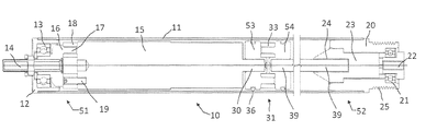
- FIG. 1 shows the motorized transport roller, seen in section, according to a first embodiment of the present invention
- FIG. 2 shows the motorized transport roller, seen in section, according to a second embodiment of the present invention
- FIG. 3 shows a connection block between the idle head and the motor of a motorized transport roller, seen in section and in perspective, according to the present invention
- FIG. 4 shows an element of a motorized transport roller disconnection element, seen in section and in perspective, according to the present invention
- FIG. 5 shows a disconnection intermediate ring of a motorized transport roller, seen in front and in section, according to the present invention.
- a motorized transport roller 10 comprises a hollow cylindrical body 11 .
- the hollow, or properly tooled cylindrical body 11 can have different dimensions according to the needs and is normally made from a steel, galvanized steel, stainless steel tube, or other materials, having 50 mm diameter and 1.5 mm thickness, or greater if necessary.
- the body 11 for particular applications may have different shapes such as a convex one.
- the body 11 has an idle head 51 , preferably antistatic, which comprises a bushing 12 , rigidly fixed to the body 11 in a known manner, wherein a bearing 13 is arranged.
- the bearing 13 allows the rotation of the hollow cylindrical body 11 with respect to a pin 14 .
- the pin 14 is inserted into a block 16 that has a hole for receiving it of the shape of the pin 14 .
- the block 16 from the side opposite to where the pin 14 enters, comprises at least two, preferably three, pins 17 arranged along a circumference, which are inserted into a ring 18 of an elastic material, such as rubber, provided with a plurality of holes.
- the roller 10 comprises a motor 15 , having from the side of the idle head 51 , at least two, preferably three, pins 19 which are inserted into the holes of the ring 18 .
- the ring 18 is adapted to absorb any vibrations generated by the running of the motor 15 .
- the torque produced by the motor 15 can be multiplied by a reducer in a known manner.
- the pin 14 is also hollow on its inside in order to allow the power and control cable of the motor 15 to pass therein.
- the body 11 has a motor head 52 which comprises a bushing 20 , rigidly fixed to the body 11 in a known manner, wherein a bearing 21 is arranged.
- the bearing 21 allows the bushing 20 to rotate in an independent manner with respect to a floating mounting pin 22 .
- an insert 23 is rigidly fixed, which has a hole 24 having a polygonal section in its side facing the inside of the body 11 .
- the insert 23 comprises on its outside longitudinal grooves that interfere with longitudinal fins internally arranged inside the bushing 20 , so as to allow assembly using only the interference.
- the bushing 20 and the insert 23 can be obtained in a single piece.
- the bushing 20 in the first embodiment, extends outside of the body 11 for a predetermined distance, and on its circular outer surface a plurality of circular recesses 25 with V-shaped profile are arranged, for use with belts for transferring the motion of the roller 10 to the adjacent rollers that may not include the motor 15 .
- crown gear or systems not integral with the body 11 or friction systems can be provided.
- the motor 15 has its own motor shaft 30 which protrudes from the motor 15 towards the motor head 52 .
- the motorized transport roller 10 comprises a device called disconnection element 31 formed by two identical and contrasting bodies, joined together by an intermediate ring 33 .
- the body 53 is on the left towards the motor 15 and the body 54 is on the right towards the insert 23 .
- the body 53 (and 54 ) is a substantially cylindrical structure having on one side a polygonal central hole 34 , and on the other side three cylindrical pins 35 which extend towards the outside of the body 53 , preferably arranged equally spaced along a circumference.
- the pins 35 being at least two may be variable in number and shape.
- the bodies 53 , 54 and the intermediate ring 33 have a diameter less than the diameter of the body 11 , so as to rotate freely inside the body 11 .
- the body 53 (and 54 ) has a circumferential groove 50 in which a gasket 36 used only for centering the body 53 (and 54 ) inside the hollow cylindrical body 11 is arranged.
- the gasket 36 due to its intrinsic structure, is not suited to transfer any motion to the body 11 and it also rotates with the bodies 53 and 54 .
- the intermediate ring 33 has a cylindrical shape and has six holes 37 , possibly through holes, and alternated with the holes 37 , in one embodiment of the present invention, there are six recesses 38 having a rectangular section and preferably of a size less than that of the holes 37 , allowing greater torsional elasticity to the ring 33 .
- the bodies 53 and 54 are joined together by way of the ring 33 .
- the three pins 35 of the left body 53 are inserted into three holes 37 of the ring 33
- the pins 35 of the right body 54 are inserted into the holes 37 previously left free.
- the pins 35 and the holes 37 can be of different number and of different shape according to the needs.
- the left body 53 receives the motor shaft 30 in the hole 34 .
- a transmission shaft 39 having preferably a polygonal section, is inserted, from one side, into the hole 34 of the right body 54 , and on the other side into the hole 24 of the insert 23 .
- the transmission shaft 39 as also the shaft 14 and the shaft 30 , are preferably polygonal in order to ensure integral fixing with the adjacent bodies without the use of other locking means.
- the pins 14 and 22 are arranged to be rigidly fixed, in a known manner, onto a frame of a transport system. In this way the pins 14 and 22 are fixed allowing the body 11 to rotate as a result of the actuation of the motor 15 .
- the motor 15 rotates its motor shaft 30 which transfers its motion to the shaft 39 by means of the disconnection element 31 .
- the shaft 39 rotates the insert 23 (if present) and therefore the bushing 20 about the pin 22 . Since the head 20 is integral and rigidly connected with the inner surface of the body 11 of the roller, it rotates the body 11 independently from the pins 14 and 22 . Therefore, the motor 15 transfers the motion to the body 11 by means of the succession of the elements 30 , 53 , 33 , 54 , 39 , 23 (if the case) and 20 .
- a bushing 40 in place of the bushing 20 a bushing 40 is provided, rigidly fixed to the body 11 in a known manner, which does not extend outside of the body and therefore not having the V shaped circular grooves 25 .
- the bushing 40 in its side facing inside the body 11 has a hole 24 having a polygonal section, like the insert 23 .
- the bushing 40 also has a bearing 21 that allows it to rotate around a floating pin 22 .
- the motor 15 transfers the motion to the body 11 by means of the succession of the elements 30 , 53 , 33 , 54 39 and 40 .
- the body 53 and 54 is preferably made of a rigid plastic material e.g. a technopolymer such as nylon.
- the ring 33 is preferably made of a plastic material with elastic properties such as rubber.
- the drive shaft 39 is preferably made of metal.
- the disconnection element 31 is designed to decouple the motor shaft 30 from the remaining part of the roller.
- the disconnection element 31 also has a vibration damping function and constitutes an adequate resistant type counter torque absorption system as compared to the torque supplied by the motor 15 , thanks to the ring 33 .
- the drive shaft 39 having an appropriate size and shape for transmitting the torque provided by the motor 15 , is housed, with appropriate interlocking, in the disconnection element 31 and in the insert 23 .
- Said shaft has suitable stiffness for not flecting (within certain limits) inside the tube.
- the length of the shaft 39 is proportional to the length of the roller according to optimized parameters.
- the motion of the motor 15 is transmitted to the bushing 20 which has the recesses 25 , where the transferring of motion to the other RollerDrives in the system occurs.
- the motion would be in any case transmitted to the other rollers by means of the bushing 20 . This is because the body 11 is not a drive element as in other cases of the prior art.
- the disconnection element 31 has been made so that it is placed very near to the motor 15 , in order to have a shaft 39 of as free as possible dimension and at the same time have, if necessary, a RollerDrive of extremely small size, also eliminating the disconnection element 31 and inserting the motor shaft 30 directly into the insert 23 .
- the materials used, as well as the dimensions, may be any according to the requirements and the state of the art.
- the motorized transport roller thus conceived is susceptible to numerous modifications and variations, all falling within the inventive concept; moreover, all details are replaceable by technically equivalent elements.
Landscapes
- Engineering & Computer Science (AREA)
- Mechanical Engineering (AREA)
- Rollers For Roller Conveyors For Transfer (AREA)
- Preliminary Treatment Of Fibers (AREA)
- Rolls And Other Rotary Bodies (AREA)
- Delivering By Means Of Belts And Rollers (AREA)
Applications Claiming Priority (4)
| Application Number | Priority Date | Filing Date | Title |
|---|---|---|---|
| ITBG2013A000031 | 2013-10-11 | ||
| ITBG2013A0031 | 2013-10-11 | ||
| IT000031A ITBG20130031A1 (it) | 2013-10-11 | 2013-10-11 | Rullo di trasporto motorizzato |
| PCT/IB2014/065085 WO2015052631A1 (en) | 2013-10-11 | 2014-10-06 | Motorized transport roller |
Publications (2)
| Publication Number | Publication Date |
|---|---|
| US20160257496A1 US20160257496A1 (en) | 2016-09-08 |
| US9731900B2 true US9731900B2 (en) | 2017-08-15 |
Family
ID=49780134
Family Applications (1)
| Application Number | Title | Priority Date | Filing Date |
|---|---|---|---|
| US15/028,383 Active US9731900B2 (en) | 2013-10-11 | 2014-10-06 | Motorized transport roller |
Country Status (10)
| Country | Link |
|---|---|
| US (1) | US9731900B2 (da) |
| EP (1) | EP3055232B1 (da) |
| CN (1) | CN105612113B (da) |
| DK (1) | DK3055232T3 (da) |
| ES (1) | ES2646949T3 (da) |
| HU (1) | HUE034993T2 (da) |
| IT (1) | ITBG20130031A1 (da) |
| PL (1) | PL3055232T3 (da) |
| SI (1) | SI3055232T1 (da) |
| WO (1) | WO2015052631A1 (da) |
Cited By (12)
| Publication number | Priority date | Publication date | Assignee | Title |
|---|---|---|---|---|
| US9994398B1 (en) * | 2016-08-16 | 2018-06-12 | Tech-Roll Inc. | Powered roller systems and methods |
| US10301118B2 (en) * | 2014-10-30 | 2019-05-28 | Interroll Holding Ag | Conveyor device for conveyor installations, a modular system, and a method for producing such a conveyor device |
| US10545488B2 (en) | 2015-04-20 | 2020-01-28 | Interroll Holding Ag | Method for replacing a control unit in a conveying device |
| US10556754B2 (en) | 2015-04-20 | 2020-02-11 | Interroll Holding Ag | Installation method for setting up conveying devices |
| US10562711B2 (en) | 2016-06-30 | 2020-02-18 | Interroll Holding Ag | Modular system for motor-operated conveying rollers |
| US10569955B2 (en) | 2017-03-09 | 2020-02-25 | Interroll Holding Ag | Intralogistic arrangement |
| US10640296B2 (en) | 2016-06-30 | 2020-05-05 | Interroll Holding Ag | Drum motor with alternative transmission mount |
| US10676285B2 (en) | 2016-08-08 | 2020-06-09 | Interroll Holding Ag | Electrical plug connector for motorized rollers |
| US11018558B2 (en) | 2016-08-05 | 2021-05-25 | Interroll Holding Ag | Drum motor with frequency converter and optional belt tension sensor |
| US11254511B2 (en) * | 2017-08-17 | 2022-02-22 | Interroll Holding Ag | Hybrid cover |
| US11309767B2 (en) | 2016-06-30 | 2022-04-19 | Interroll Holding Ag | Drive unit for a drum motor, drum motor, rear flange and production method |
| US11358803B2 (en) | 2015-05-07 | 2022-06-14 | Interroll Holding Ag | Control unit for a conveyor with hardware detection |
Families Citing this family (6)
| Publication number | Priority date | Publication date | Assignee | Title |
|---|---|---|---|---|
| EP3034437B1 (de) | 2014-12-15 | 2018-10-31 | MTA Systems GmbH | Antriebseinheit für eine Transportrolle |
| US9630784B2 (en) * | 2015-05-15 | 2017-04-25 | Laitram, L.L.C. | Transfer-roller destacker |
| EP3715285B1 (en) * | 2019-03-08 | 2024-05-01 | Intelligrated Headquarters LLC | Motorized conveyor roller with drive assembly |
| CN115592754A (zh) * | 2022-10-25 | 2023-01-13 | 广西柯瑞机械设备有限公司(Cn) | 一种内置驱动压辊 |
| JP7795204B2 (ja) * | 2022-10-25 | 2026-01-07 | 株式会社協和製作所 | コンベア用モータ内蔵ローラおよびコンベア装置 |
| KR102934491B1 (ko) * | 2025-09-12 | 2026-03-05 | (주)에스알파트너 | 전동 롤러 구조 |
Citations (9)
| Publication number | Priority date | Publication date | Assignee | Title |
|---|---|---|---|---|
| US5088596A (en) * | 1990-12-17 | 1992-02-18 | Interroll Holding A. G. | Motorized conveyor roller |
| US5180344A (en) | 1992-03-23 | 1993-01-19 | Interroll Holding A.G. | Motorized pulley with internal mounts |
| DE19618248C1 (de) * | 1996-05-07 | 1997-10-16 | Maul Hans Erich | Trommelmotor |
| DE102004014989A1 (de) | 2003-03-27 | 2005-01-13 | Sumitomo Heavy Industries, Ltd. | Kühlstruktur für eine motorisierte Walze |
| DE102006049327A1 (de) * | 2006-10-19 | 2008-04-24 | Siemens Ag | Rollenantriebssystem mit Schwingungsdämpfung |
| EP1947035A1 (en) | 2007-01-16 | 2008-07-23 | Itoh Denki Co., Ltd. | Sorter and roller-conveying system incorporating the sorter |
| US8381901B2 (en) * | 2008-05-16 | 2013-02-26 | Kyowa Manufacturing Co., Ltd. | Roller conveyor motorized roller and roller conveyor device using the same |
| US20130334012A1 (en) * | 2012-06-01 | 2013-12-19 | Interroll Holding Ag | Motorized Conveyor Roller for Conveyor Systems for Conveying Containers, Pallets and the Like |
| US20150210479A1 (en) * | 2014-01-30 | 2015-07-30 | Interroll Holding Ag | Sync motor with reduced noise level |
Family Cites Families (2)
| Publication number | Priority date | Publication date | Assignee | Title |
|---|---|---|---|---|
| DE10336304B4 (de) * | 2003-07-31 | 2020-08-27 | Interroll Holding Ag | Motorbetriebene Förderrolle, Steuervorrichtung für eine motorbetriebene Förderrolle, Rollenförderanlage und Steuerverfahren für eine Rollenförderanlage |
| US7618352B1 (en) * | 2009-05-11 | 2009-11-17 | Ta-Chuang Wei | Driving mechanism for treadmill |
-
2013
- 2013-10-11 IT IT000031A patent/ITBG20130031A1/it unknown
-
2014
- 2014-10-06 SI SI201430483T patent/SI3055232T1/sl unknown
- 2014-10-06 HU HUE14796278A patent/HUE034993T2/en unknown
- 2014-10-06 PL PL14796278T patent/PL3055232T3/pl unknown
- 2014-10-06 DK DK14796278.1T patent/DK3055232T3/da active
- 2014-10-06 CN CN201480055835.5A patent/CN105612113B/zh active Active
- 2014-10-06 EP EP14796278.1A patent/EP3055232B1/en active Active
- 2014-10-06 ES ES14796278.1T patent/ES2646949T3/es active Active
- 2014-10-06 WO PCT/IB2014/065085 patent/WO2015052631A1/en not_active Ceased
- 2014-10-06 US US15/028,383 patent/US9731900B2/en active Active
Patent Citations (9)
| Publication number | Priority date | Publication date | Assignee | Title |
|---|---|---|---|---|
| US5088596A (en) * | 1990-12-17 | 1992-02-18 | Interroll Holding A. G. | Motorized conveyor roller |
| US5180344A (en) | 1992-03-23 | 1993-01-19 | Interroll Holding A.G. | Motorized pulley with internal mounts |
| DE19618248C1 (de) * | 1996-05-07 | 1997-10-16 | Maul Hans Erich | Trommelmotor |
| DE102004014989A1 (de) | 2003-03-27 | 2005-01-13 | Sumitomo Heavy Industries, Ltd. | Kühlstruktur für eine motorisierte Walze |
| DE102006049327A1 (de) * | 2006-10-19 | 2008-04-24 | Siemens Ag | Rollenantriebssystem mit Schwingungsdämpfung |
| EP1947035A1 (en) | 2007-01-16 | 2008-07-23 | Itoh Denki Co., Ltd. | Sorter and roller-conveying system incorporating the sorter |
| US8381901B2 (en) * | 2008-05-16 | 2013-02-26 | Kyowa Manufacturing Co., Ltd. | Roller conveyor motorized roller and roller conveyor device using the same |
| US20130334012A1 (en) * | 2012-06-01 | 2013-12-19 | Interroll Holding Ag | Motorized Conveyor Roller for Conveyor Systems for Conveying Containers, Pallets and the Like |
| US20150210479A1 (en) * | 2014-01-30 | 2015-07-30 | Interroll Holding Ag | Sync motor with reduced noise level |
Cited By (12)
| Publication number | Priority date | Publication date | Assignee | Title |
|---|---|---|---|---|
| US10301118B2 (en) * | 2014-10-30 | 2019-05-28 | Interroll Holding Ag | Conveyor device for conveyor installations, a modular system, and a method for producing such a conveyor device |
| US10545488B2 (en) | 2015-04-20 | 2020-01-28 | Interroll Holding Ag | Method for replacing a control unit in a conveying device |
| US10556754B2 (en) | 2015-04-20 | 2020-02-11 | Interroll Holding Ag | Installation method for setting up conveying devices |
| US11358803B2 (en) | 2015-05-07 | 2022-06-14 | Interroll Holding Ag | Control unit for a conveyor with hardware detection |
| US10562711B2 (en) | 2016-06-30 | 2020-02-18 | Interroll Holding Ag | Modular system for motor-operated conveying rollers |
| US10640296B2 (en) | 2016-06-30 | 2020-05-05 | Interroll Holding Ag | Drum motor with alternative transmission mount |
| US11309767B2 (en) | 2016-06-30 | 2022-04-19 | Interroll Holding Ag | Drive unit for a drum motor, drum motor, rear flange and production method |
| US11018558B2 (en) | 2016-08-05 | 2021-05-25 | Interroll Holding Ag | Drum motor with frequency converter and optional belt tension sensor |
| US10676285B2 (en) | 2016-08-08 | 2020-06-09 | Interroll Holding Ag | Electrical plug connector for motorized rollers |
| US9994398B1 (en) * | 2016-08-16 | 2018-06-12 | Tech-Roll Inc. | Powered roller systems and methods |
| US10569955B2 (en) | 2017-03-09 | 2020-02-25 | Interroll Holding Ag | Intralogistic arrangement |
| US11254511B2 (en) * | 2017-08-17 | 2022-02-22 | Interroll Holding Ag | Hybrid cover |
Also Published As
| Publication number | Publication date |
|---|---|
| PL3055232T3 (pl) | 2018-01-31 |
| US20160257496A1 (en) | 2016-09-08 |
| SI3055232T1 (sl) | 2017-12-29 |
| CN105612113B (zh) | 2018-08-31 |
| ITBG20130031A1 (it) | 2015-04-12 |
| CN105612113A (zh) | 2016-05-25 |
| ES2646949T3 (es) | 2017-12-18 |
| HUE034993T2 (en) | 2018-05-02 |
| EP3055232A1 (en) | 2016-08-17 |
| WO2015052631A1 (en) | 2015-04-16 |
| DK3055232T3 (da) | 2017-11-27 |
| EP3055232B1 (en) | 2017-08-23 |
Similar Documents
| Publication | Publication Date | Title |
|---|---|---|
| US9731900B2 (en) | Motorized transport roller | |
| US11136194B2 (en) | Motorized conveyor roller with drive assembly | |
| KR101028045B1 (ko) | 벨트 컨베이어 장치 | |
| CN102959262A (zh) | 具有超越能力和振动阻尼能力的隔离带轮 | |
| US9611100B2 (en) | Load-bearing roller and conveying device using same | |
| CN104816920A (zh) | 用于噪声敏感的环境的电动滚筒 | |
| KR102214089B1 (ko) | 컨베이어에 채용되는 볼베어링의 외륜체 제동력 유지용 프릭션 롤러 | |
| JP5275477B2 (ja) | 動力伝達装置 | |
| KR20180031128A (ko) | 컨베이어용 프릭션 롤러 | |
| CN105980274A (zh) | 带式传送机装置用的驱动装置 | |
| CN104718144A (zh) | 具有头部元件的输送滚筒 | |
| KR101716046B1 (ko) | 컨베이어용 프릭션 롤러 | |
| KR101366789B1 (ko) | 터닝 체인 컨베이어 | |
| KR101770037B1 (ko) | 컨베이어용 프릭션 롤러 | |
| JP2005272102A (ja) | ローラ式搬送装置 | |
| KR101507295B1 (ko) | 컨베이어용 프릭션 롤러 | |
| KR20030038242A (ko) | 영구자석 기어조합체 및 이를 이용한 컨베이어 | |
| HK1225002A1 (en) | Motorized transport roller | |
| HK1225002B (zh) | 机动输送辊 | |
| JP4596412B2 (ja) | 駆動ユニット | |
| JP5352105B2 (ja) | カーブベルトコンベヤ | |
| US8684848B2 (en) | Shaft coupling apparatus | |
| KR102799342B1 (ko) | 컨베이어용 프릭션 롤러 | |
| JP2007197149A (ja) | 拡張ベルトコンベヤ | |
| KR20080105223A (ko) | 반원형 커브벨트 컨베이어 |
Legal Events
| Date | Code | Title | Description |
|---|---|---|---|
| AS | Assignment |
Owner name: RULLI RULMECA S.P.A., ITALY Free format text: ASSIGNMENT OF ASSIGNORS INTEREST;ASSIGNOR:RUGGERI, GIOVANNI;REEL/FRAME:038399/0293 Effective date: 20160330 |
|
| STCF | Information on status: patent grant |
Free format text: PATENTED CASE |
|
| MAFP | Maintenance fee payment |
Free format text: PAYMENT OF MAINTENANCE FEE, 4TH YEAR, LARGE ENTITY (ORIGINAL EVENT CODE: M1551); ENTITY STATUS OF PATENT OWNER: LARGE ENTITY Year of fee payment: 4 |
|
| MAFP | Maintenance fee payment |
Free format text: PAYMENT OF MAINTENANCE FEE, 8TH YEAR, LARGE ENTITY (ORIGINAL EVENT CODE: M1552); ENTITY STATUS OF PATENT OWNER: LARGE ENTITY Year of fee payment: 8 |