US973038A - Impression or imitation stitch machine. - Google Patents
Impression or imitation stitch machine. Download PDFInfo
- Publication number
- US973038A US973038A US23615804A US1904236158A US973038A US 973038 A US973038 A US 973038A US 23615804 A US23615804 A US 23615804A US 1904236158 A US1904236158 A US 1904236158A US 973038 A US973038 A US 973038A
- Authority
- US
- United States
- Prior art keywords
- wheel
- shoe
- indenting
- guard
- impression
- Prior art date
- Legal status (The legal status is an assumption and is not a legal conclusion. Google has not performed a legal analysis and makes no representation as to the accuracy of the status listed.)
- Expired - Lifetime
Links
- 238000007373 indentation Methods 0.000 description 5
- 208000027418 Wounds and injury Diseases 0.000 description 1
- 230000006378 damage Effects 0.000 description 1
- 208000014674 injury Diseases 0.000 description 1
- 238000007689 inspection Methods 0.000 description 1
- 238000004519 manufacturing process Methods 0.000 description 1
Images
Classifications
-
- A—HUMAN NECESSITIES
- A43—FOOTWEAR
- A43D—MACHINES, TOOLS, EQUIPMENT OR METHODS FOR MANUFACTURING OR REPAIRING FOOTWEAR
- A43D93/00—Edge-indenting machines
Definitions
- the present invention relates to impression or imitation stitch machines which are used in the manufacture of boots and shoes to form ornamental indentations upon the upper surface of the projecting edge of the sole.
- Impression or imitation stitch machines usually comprise a rotary indenting wheel provided with teeth so shaped and spaced as to produce the desired form of indenta tion when the edge of the shoe sole is passed beneath the wheel.
- a guard has usually been provided for preventing the shoe upper from coming in contact with and being marred by the end of the indenting'wheel.
- This guard has consisted of a thin plate so located as to extend across the end of the wheel between the wheel and the shoe upper. The provision of this guard plate has been found to be objectionable, as the plate holds the shoe away from the wheel and prevents the shoe from being manipulated so as to cause the teeth of'the wheel to extend into the crease between the upper and the projecting edge of the shoe sole.
- the object of the present invention is to provide an indenting wheel which will allow the shoe to be manipulated so as to cause the teeth of the tool to extend into the crease between the upper and the projecting edge of the sole without liability of injury to the upper by contact with the end of the wheel.
- Another object of the invention is to provlde an impression or imitation stitch machine with a guard for the upper which will guide the shoe and at the same time permitthe upper to be brought close to the end of the indenting wheel.
- the present invention consists in the improved form of indenting wheel and in the improved guard for guiding the shoe and holding the upper out of contact with the indenting wheel hereinafter described and claimed.
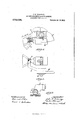
- FIG. l is a view in side elevation of a portion of an impression or imitation stitch machine embodying the same in their preferred form, the guard for the upper being broken away, the indenting wheel being shown in section, and the toe portion of a shoe being shown in position to be acted upon by the indenting wheel;
- Fig. 2 is a plan View partly in section of the parts illustrated in Fig. 1
- Fig. 3 is an end view of the indenting wheel and guard, showing the projecting edge of the shoe sole in cross section.
- indenting wheel which is frusto-conical in shape, as is usual in this class of machines, and which is provided upon its periphery with teeth shaped and spaced to produce the desired form of indentation.
- This wheel is mounted upon the outer end of a shaft 2 with its larger end extending beyond the end of the shaft.
- the shaft 2 is journaled in a bearing 3, and is secured to the shaft by means of a headed screw 4 screwing into the end of the shaft.
- a recess 7 is provided in the end of the i11- denting wheel, as is clearly shown in Fig. 1.
- This recess provides a space into which the bulging portion of the upper at the toe portion of the shoe can project without coming into contact with the end of the indenting wheel or the head of the screw 4, so that when the toe portion of the shoe is being operated upon the shoe can be pressed toward the wheel to cause the teeth of the wheel to extend into the crease between the upper and the projecting edge of the sole.
- the periphery of the wheel is beveled off at its outer edge as indicated in Figs. 1 and 2 so that the outer edge of the wheel is smooth and will not mar the upper if brought accidentally into engagement therewith.
- the recess flares outwardly toward the periphery of the outer end of the wheel to allow the teeth of the wheel to more readily extend into the crease between the upper and the sole.
- the surface of the recess is smooth and if desired the shoe can be forced toward the wheel until the upper contacts with the surface of the recess as indicated in Fig. 1, and the portion of the wheel which extends into the crease between the upper and the sole forms a guide for the shoe.
- the guard 6 is arranged to bear against the shoe upper at one side of the indenting wheel as indicated in Figs. 2 and 3, the surface of the guide which contacts with the shoe upper being located substantially flush with the end of the indenting wheel or slightly beyond the end of the wheel.
- the guard extends circumferentially about the indenting wheel, and no portion of the guard extends into a position to contact with the upper in front of the indenting wheel and prevent the upper from being brought close to the end of the wheel.
- the guard so as to cause its upper engaging surface to project more or less beyond the end of the indenting wheel,
- the guard is secured to a stationary portion 8 of the machine frame by means of a bolt 9 passing through a slot in the frame and screwing into the rear portion of the guard.
- the guard can be used advantageously in connection with the usual form of indenting wheel, which is not provided at its end with a recess to receive the bulging portion of the upper.
- a machine for making impression or imitation stitches having, in combination, a shaft, a frusto-conical indenting wheel mounted thereon with its larger end extending beyond the outer end of the shaft, and'a guard having a surface substantially flush with the larger end of the indenting wheel mounted to bear against the shoe upper at one side of the indenting wheel and guide the shoe while permitting the upper to be brought close to the end of the indenting wheel, substantially as described.
- a machine for making impression or imitation stitches having, in combination, a shaft, a frusto-conical indenting wheel mounted thereon with its larger end extending beyond the outer end of the shaft, said indenting wheel being provided at its larger end with a recess to receive the bulging portion of the upper at the toe of the shoe, and a guard arranged to bear against the upper at one side of the indenting wheel, substantially as described.
Landscapes
- Footwear And Its Accessory, Manufacturing Method And Apparatuses (AREA)
Description
J, B. HADAWAY. IMPRESSION 0R IMITATION STITCH MACHINE. ABPLIOATION FILED D30. 9. 1904.
973,038. Patented Oct. 18,1910.
Zgamaszs'es WW2" IHS NoRms PETERS co., wnsumqrou, n. c.
time s'ras ET FFIC.
JOHN B. HADAWAY, OF BROCKTON, MASSACHUSETTS, ASSIGNOR TO UNITED SHOE MACHINERY COMPANY, OF PATERSON, NEW JERSEY, A CORPORATION OF NE JERSEY.
Specification of Letters Patent.
Patented Oct. 18, 1910.
Application filed December 9, 1904. Serial No. 236,158.
T 0 all whom it may concern:
Be it known that I, JOHN B. HADAWAY, a citizen of the United States, residing at Brockton, in the county of Plymouth and State of Massachusetts, have invented certain new and useful Improvements in Impression or Imitation Stitch Machines; and I do hereby declare the following to be a full, clear, and exact description of the in vention, such as will enable others skilled in the art to which it appertains to make and use the same.
The present invention relates to impression or imitation stitch machines which are used in the manufacture of boots and shoes to form ornamental indentations upon the upper surface of the projecting edge of the sole.
Impression or imitation stitch machines usually comprise a rotary indenting wheel provided with teeth so shaped and spaced as to produce the desired form of indenta tion when the edge of the shoe sole is passed beneath the wheel. In machines of this class as heretofore constructed a guard has usually been provided for preventing the shoe upper from coming in contact with and being marred by the end of the indenting'wheel. This guard has consisted of a thin plate so located as to extend across the end of the wheel between the wheel and the shoe upper. The provision of this guard plate has been found to be objectionable, as the plate holds the shoe away from the wheel and prevents the shoe from being manipulated so as to cause the teeth of'the wheel to extend into the crease between the upper and the projecting edge of the shoe sole. The interference of this guard plate with the proper manipulation of the shoe is especially noticeable while the edge of the sole at the toe portion of the shoe is being indented. At this portion of the shoe the upper bulges out over the surface of the sole to a noticeable degree, and in order to cause the indentations to extend as far as possible into the crease between the upper and sole, the operator often presses the shoe against the guard plate with sufficient force to bend or break the plate or to mar the shoe upper. In case no guard plate is provided great care is required on the part of the operator while the toe portion of the sole edge is being acted upon to cause the indentations to be properly located and at the same time prevent the upper from coming in contactwith and being injured by the end of the indenting wheel.
The object of the present invention is to provide an indenting wheel which will allow the shoe to be manipulated so as to cause the teeth of the tool to extend into the crease between the upper and the projecting edge of the sole without liability of injury to the upper by contact with the end of the wheel.
Another object of the invention is to provlde an impression or imitation stitch machine with a guard for the upper which will guide the shoe and at the same time permitthe upper to be brought close to the end of the indenting wheel.
With these objects in view, the present invention consists in the improved form of indenting wheel and in the improved guard for guiding the shoe and holding the upper out of contact with the indenting wheel hereinafter described and claimed.
The several features of the present invention will be clearly understood from an inspection of the accompanying drawings, in which- Figure l is a view in side elevation of a portion of an impression or imitation stitch machine embodying the same in their preferred form, the guard for the upper being broken away, the indenting wheel being shown in section, and the toe portion of a shoe being shown in position to be acted upon by the indenting wheel; Fig. 2 is a plan View partly in section of the parts illustrated in Fig. 1, and Fig. 3 is an end view of the indenting wheel and guard, showing the projecting edge of the shoe sole in cross section.
1 indicates an indenting wheel which is frusto-conical in shape, as is usual in this class of machines, and which is provided upon its periphery with teeth shaped and spaced to produce the desired form of indentation. This wheel is mounted upon the outer end of a shaft 2 with its larger end extending beyond the end of the shaft. The shaft 2 is journaled in a bearing 3, and is secured to the shaft by means of a headed screw 4 screwing into the end of the shaft.
5 indicates the work support upon which the tread surface of the shoe sole is supported during the indenting operation, and
6 indicates a guard arranged to engage the shoe upper and prevent the upper from coming in contact with the indenting wheel.
In accordance with the present invention, a recess 7 is provided in the end of the i11- denting wheel, as is clearly shown in Fig. 1. This recess provides a space into which the bulging portion of the upper at the toe portion of the shoe can project without coming into contact with the end of the indenting wheel or the head of the screw 4, so that when the toe portion of the shoe is being operated upon the shoe can be pressed toward the wheel to cause the teeth of the wheel to extend into the crease between the upper and the projecting edge of the sole. Preferably the periphery of the wheel is beveled off at its outer edge as indicated in Figs. 1 and 2 so that the outer edge of the wheel is smooth and will not mar the upper if brought accidentally into engagement therewith. Also preferably the recess flares outwardly toward the periphery of the outer end of the wheel to allow the teeth of the wheel to more readily extend into the crease between the upper and the sole. The surface of the recess is smooth and if desired the shoe can be forced toward the wheel until the upper contacts with the surface of the recess as indicated in Fig. 1, and the portion of the wheel which extends into the crease between the upper and the sole forms a guide for the shoe. Also, in accordance with the present invention the guard 6 is arranged to bear against the shoe upper at one side of the indenting wheel as indicated in Figs. 2 and 3, the surface of the guide which contacts with the shoe upper being located substantially flush with the end of the indenting wheel or slightly beyond the end of the wheel. As illustrated, the guard extends circumferentially about the indenting wheel, and no portion of the guard extends into a position to contact with the upper in front of the indenting wheel and prevent the upper from being brought close to the end of the wheel. To provide means for adjusting the guard so as to cause its upper engaging surface to project more or less beyond the end of the indenting wheel,
the guard is secured to a stationary portion 8 of the machine frame by means of a bolt 9 passing through a slot in the frame and screwing into the rear portion of the guard.
It is preferred to use the improved form of guard above described with the improved form of indenting wheel, as when these parts are used together the shoe can be accurately guided to cause the teeth of the indenting wheel to extend into the crease between the upper and the projecting edge of the sole without any liability of injuring the upper.
It will be evident however that the guard can be used advantageously in connection with the usual form of indenting wheel, which is not provided at its end with a recess to receive the bulging portion of the upper.
The invention having been thus described, what is claimed is I 1. A machine for making impression or imitation stitches, having, in combination, a shaft, a frusto-conical indenting wheel mounted thereon with its larger end extending beyond the outer end of the shaft, and'a guard having a surface substantially flush with the larger end of the indenting wheel mounted to bear against the shoe upper at one side of the indenting wheel and guide the shoe while permitting the upper to be brought close to the end of the indenting wheel, substantially as described.
2. A machine for making impression or imitation stitches, having, in combination, a shaft, a frusto-conical indenting wheel mounted thereon with its larger end extending beyond the outer end of the shaft, said indenting wheel being provided at its larger end with a recess to receive the bulging portion of the upper at the toe of the shoe, and a guard arranged to bear against the upper at one side of the indenting wheel, substantially as described.
In testimony whereof I afliX my signature, in presence of two witnesses.
JOHN B. HADAWAY.
lVitnesses:
FRED O. FISH, FARNUM F. DORSEY.
Priority Applications (1)
| Application Number | Priority Date | Filing Date | Title |
|---|---|---|---|
| US23615804A US973038A (en) | 1904-12-09 | 1904-12-09 | Impression or imitation stitch machine. |
Applications Claiming Priority (1)
| Application Number | Priority Date | Filing Date | Title |
|---|---|---|---|
| US23615804A US973038A (en) | 1904-12-09 | 1904-12-09 | Impression or imitation stitch machine. |
Publications (1)
| Publication Number | Publication Date |
|---|---|
| US973038A true US973038A (en) | 1910-10-18 |
Family
ID=3041417
Family Applications (1)
| Application Number | Title | Priority Date | Filing Date |
|---|---|---|---|
| US23615804A Expired - Lifetime US973038A (en) | 1904-12-09 | 1904-12-09 | Impression or imitation stitch machine. |
Country Status (1)
| Country | Link |
|---|---|
| US (1) | US973038A (en) |
-
1904
- 1904-12-09 US US23615804A patent/US973038A/en not_active Expired - Lifetime
Similar Documents
| Publication | Publication Date | Title |
|---|---|---|
| US209091A (en) | Improvement in boot-jacks | |
| US999049A (en) | Top lift. | |
| US921134A (en) | Fastening device. | |
| US570830A (en) | Detachable heel | |
| US858681A (en) | Shoe-tongue support. | |
| US1020135A (en) | Sole-holding device. | |
| US373840A (en) | Shoe-last | |
| US1017742A (en) | Method of making boots and shoes. | |
| US1056458A (en) | Heel. | |
| US1030285A (en) | Welt-guide. | |
| US930510A (en) | Heel-indenting machine. | |
| US243422A (en) | Crimping-form for boots and shoes | |
| US1021821A (en) | Last. | |
| US226894A (en) | Sole and heel plate for boots and shoes | |
| US134736A (en) | Improvement in heel-stiffeners | |
| US1232677A (en) | Heel for shoes. | |
| US968556A (en) | Vamp-trimming machine. | |
| US200788A (en) | Improvement in peg-cutters | |
| US545881A (en) | Last for leveling-machines | |
| US1036649A (en) | Apparatus for shaping boot and shoe uppers. | |
| US1113540A (en) | Insole. | |
| US673131A (en) | Last. | |
| US957697A (en) | Presser-foot for shoe-sole-stitching mechanisms. | |
| US942919A (en) | Needle-guide. | |
| USRE7686E (en) | Improvement in boot and shoe crimping machines |