US9711175B2 - Magnetic-disk substrate having a small waviness, for use as a magnetic disk, and a magnetic-disk drive device for use with the magnetic disk - Google Patents
Magnetic-disk substrate having a small waviness, for use as a magnetic disk, and a magnetic-disk drive device for use with the magnetic disk Download PDFInfo
- Publication number
- US9711175B2 US9711175B2 US15/107,764 US201415107764A US9711175B2 US 9711175 B2 US9711175 B2 US 9711175B2 US 201415107764 A US201415107764 A US 201415107764A US 9711175 B2 US9711175 B2 US 9711175B2
- Authority
- US
- United States
- Prior art keywords
- magnetic
- disk
- waviness
- polishing
- glass substrate
- Prior art date
- Legal status (The legal status is an assumption and is not a legal conclusion. Google has not performed a legal analysis and makes no representation as to the accuracy of the status listed.)
- Active
Links
Images


Classifications
-
- G—PHYSICS
- G11—INFORMATION STORAGE
- G11B—INFORMATION STORAGE BASED ON RELATIVE MOVEMENT BETWEEN RECORD CARRIER AND TRANSDUCER
- G11B5/00—Recording by magnetisation or demagnetisation of a record carrier; Reproducing by magnetic means; Record carriers therefor
- G11B5/62—Record carriers characterised by the selection of the material
- G11B5/73—Base layers, i.e. all non-magnetic layers lying under a lowermost magnetic recording layer, e.g. including any non-magnetic layer in between a first magnetic recording layer and either an underlying substrate or a soft magnetic underlayer
- G11B5/739—Magnetic recording media substrates
- G11B5/73911—Inorganic substrates
- G11B5/73921—Glass or ceramic substrates
-
- G11B5/7315—
-
- G—PHYSICS
- G11—INFORMATION STORAGE
- G11B—INFORMATION STORAGE BASED ON RELATIVE MOVEMENT BETWEEN RECORD CARRIER AND TRANSDUCER
- G11B5/00—Recording by magnetisation or demagnetisation of a record carrier; Reproducing by magnetic means; Record carriers therefor
- G11B5/48—Disposition or mounting of heads or head supports relative to record carriers ; arrangements of heads, e.g. for scanning the record carrier to increase the relative speed
- G11B5/4806—Disposition or mounting of heads or head supports relative to record carriers ; arrangements of heads, e.g. for scanning the record carrier to increase the relative speed specially adapted for disk drive assemblies, e.g. assembly prior to operation, hard or flexible disk drives
-
- G—PHYSICS
- G11—INFORMATION STORAGE
- G11B—INFORMATION STORAGE BASED ON RELATIVE MOVEMENT BETWEEN RECORD CARRIER AND TRANSDUCER
- G11B5/00—Recording by magnetisation or demagnetisation of a record carrier; Reproducing by magnetic means; Record carriers therefor
- G11B5/62—Record carriers characterised by the selection of the material
- G11B5/73—Base layers, i.e. all non-magnetic layers lying under a lowermost magnetic recording layer, e.g. including any non-magnetic layer in between a first magnetic recording layer and either an underlying substrate or a soft magnetic underlayer
-
- G—PHYSICS
- G11—INFORMATION STORAGE
- G11B—INFORMATION STORAGE BASED ON RELATIVE MOVEMENT BETWEEN RECORD CARRIER AND TRANSDUCER
- G11B5/00—Recording by magnetisation or demagnetisation of a record carrier; Reproducing by magnetic means; Record carriers therefor
- G11B5/74—Record carriers characterised by the form, e.g. sheet shaped to wrap around a drum
- G11B5/82—Disk carriers
-
- G—PHYSICS
- G11—INFORMATION STORAGE
- G11B—INFORMATION STORAGE BASED ON RELATIVE MOVEMENT BETWEEN RECORD CARRIER AND TRANSDUCER
- G11B5/00—Recording by magnetisation or demagnetisation of a record carrier; Reproducing by magnetic means; Record carriers therefor
- G11B5/84—Processes or apparatus specially adapted for manufacturing record carriers
- G11B5/8404—Processes or apparatus specially adapted for manufacturing record carriers manufacturing base layers
Definitions
- the present invention relates to a magnetic-disk substrate, a magnetic disk, and a magnetic-disk drive device.
- HDDs hard disk drives
- DVD (digital versatile disc) recording devices or the like.
- a magnetic disk obtained by providing a magnetic recording layer on a substrate is used in a hard disk drive used in a device for which portability is a prerequisite, such as a laptop personal computer, and magnetic recording information is recorded in or read from the magnetic recording layer with a magnetic head that flies slightly away from the surface of the magnetic disk.
- a glass substrate is preferably used as a magnetic-disk substrate due to the fact that it has a property of being unlikely to undergo plastic deformation compared to a metal substrate (an aluminum alloy substrate) or the like.
- the magnetic recording information area (the recording bit) has been made smaller using a perpendicular magnetic recording method in which the direction of magnetization in the magnetic recording layer is perpendicular to the surface of the substrate.
- a perpendicular magnetic recording magnetic disk an adherent layer, a soft under layer (SUL), a base layer, a magnetic recording layer, a protecting layer, a lubricant layer, and the like are formed on a metal substrate or a glass substrate in the stated order, for example.
- the storage capacity of one disk substrate can be increased by adopting a perpendicular magnetic recording system.
- the distance from the magnetic recording layer is made extremely short by allowing only a recording and reproduction element portion of the magnetic head to further protrude from the slider surface toward the magnetic disk, thus further improving the accuracy of the recording and reproduction of information (improving the S/N ratio).
- the control of the recording and reproduction element portion of the magnetic head is called a DFH (dynamic flying height) control mechanism, and a magnetic head provided with this control mechanism is called a DFH head.
- a magnetic-disk glass substrate used in an HDD in combination with this DFH head is produced such that the surface unevenness of the substrate is as small as possible.
- the DFH control mechanism is a mechanism that performs control so as to make the distance from the head surface to the surface of the magnetic disk close to several nanometers by controlling the expansion of a reading element and writing element (collectively referred to as a “R/W element portion” hereinafter) of the head through providing a heater coil around the R/W element portion and controlling electric current that flows through the heater coil.
- a reading element and writing element collectively referred to as a “R/W element portion” hereinafter
- the surface of the magnetic disk comes into contact with the R/W element portion and the R/W element portion undergoes abrasion. Therefore, it is preferable that the surface of the magnetic disk is a smooth surface having small waviness, and in particular, the waviness of the glass substrate, which is a substrate for the magnetic disk, needs to be extremely small.
- the main flat surface of the glass substrate for a magnetic recording medium is such that upon measuring the microwavinesses (nWq) of grid-like evaluation regions that are set on the entire main flat surface including the entire surface of a region that serves as the recording and reproduction region when the glass substrate is used to prepare a magnetic disk, a percentage of an absolute value ( ⁇ nWq) of a change amount of microwavinesses between one evaluation region and an evaluation region adjacent thereto, relative to the microwaviness of the one evaluation region (change percentage) is 10% or less. Also, an average value of the microwavinesses (nWq) measured in these grid-like evaluation regions is 0.080 nm or less.
- the microwaviness has a period (a wavelength) of 0.2 ⁇ m to 1.8 ⁇ m.
- an object of the present invention is to provide a magnetic-disk substrate, a magnetic disk, and a magnetic-disk drive device with which abrasion of the R/W element portion of the DFH head can be suppressed when recording or reading is performed using the DFH head.
- An aspect of the present invention is a disk-shaped magnetic-disk substrate having a pair of main surfaces.
- waviness having a wavelength component of 10 to 500 ⁇ m on a main surface of the magnetic-disk substrate is acquired in a circumferential direction of the main surface and slopes are acquired from the waviness at an interval of 50 to 100 ⁇ m on the substrate, an average value of absolute values of the slopes is 0.45 ⁇ 10 ⁇ 4 or less.
- a ratio (Ra_rad/Ra_cir) between an arithmetic average roughness Ra_rad in a radial direction of the main surface and an arithmetic average roughness Ra_cir in the circumferential direction is in a range of 0.95 to 1.05.
- a root mean square roughness Rq of waviness having a wavelength component of 10 to 500 ⁇ m is 0.04 nm or less. It is more preferable that the root mean square roughness Rq is 0.38 nm or less.
- Another aspect of the present invention is a magnetic disk in which a magnetic layer is formed on the main surface of the magnetic-disk substrate.
- Still another aspect of the present invention is a magnetic-disk drive device including the magnetic disk, a spindle for fixing the magnetic disk, and a magnetic head.
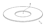
- FIG. 1 is a diagram showing the external shape of a magnetic-disk glass substrate of this embodiment.
- FIGS. 2A to 2D are diagrams showing relationships between slopes of wavinesses at certain pitch lengths and abrasion amounts.
- a magnetic-disk substrate may be a metal substrate (for example, an aluminum alloy substrate).
- the surface of the substrate has been ground and polished such that waviness having a dimension equal to the size of the entire DFH head, or specifically, having a wavelength of 60 ⁇ m to 500 ⁇ m or of 60 ⁇ m to 1000 ⁇ m is reduced.
- abrasion of the tip of the R/W element portion could not be reduced with this reduction in waviness.
- the inventor of the present invention found that the waviness having a wavelength in a specific range on a surface of the substrate caused abrasion. Specifically, the inventor found that the waviness on the surface of the magnetic-disk substrate having a wavelength that corresponds to the size of the R/W element portion protruding toward the magnetic disk from the surface of the tip of the R/W element portion that is opposite to the magnetic disk, that is, from the slider surface, affected abrasion.
- the inventor of the present invention found that there was a strong correlational relationship between an average value of the slopes of the waviness having the above-described wavelength and the magnitude of abrasion of the protruding R/W element portion, and the inventor invented a magnetic-disk substrate having the following aspects. Note that it is conceivable that the above-described phenomenon is caused by the size of the protruding portion of the R/W element portion being smaller than the size of the slider surface (the size of the entire DFH head).
- the abrasion testing for the R/W element portion of the DFH head in this specification is performed as follows.
- abrasion testing for the R/W element is performed for 15 minutes by making the R/W element portion of the DFH head fly with a back-off amount of 0.2 nm at an abrasion measurement position located a fixed distance away from the center of the magnetic disk and rotating the magnetic disk.
- the “back-off amount” indicates an amount of returning from a location at which the R/W element portion is brought into contact with the magnetic disk by causing the R/W element portion to protrude. For example, if the back-off amount is 0.5 nm, the minimum distance between the head and the magnetic disk is 0.5 nm.
- a gap between the magnetic disk and a portion other than the R/W element portion of the slider surface of the head is about 10 nm.
- the surface shape data on a main surface of a circular magnetic-disk glass substrate is acquired using an optical surface analyzer with a laser beam.
- the shape of waviness does not change due to film formation, and thus the surface shape data is acquired from a magnetic-disk substrate before the film formation. Data on the surface shape in the circumferential direction of the magnetic-disk glass substrate is acquired in this embodiment.
- the shape of waviness having a wavelength bandwidth of 10 to 500 ⁇ m is measured by performing filtering using a band-pass filter.
- the slope of the waviness referred to in this specification is found by extracting height data at an interval of ⁇ x that is determined in advance using a random position as a starting position, or for example, at an interval of 50 ⁇ m, and obtaining the slope between pieces of the extracted height data.
- the slope is (z2 ⁇ z1)/ ⁇ x where values of two adjacent pieces of extracted data are z1 and z2. Even if a random position is used as the starting position for calculating a slope as described above, the value of a stable slope can be found by finding and averaging the absolute values of such slopes.
- an average value of the absolute values of slopes of waviness on a main surface of a magnetic-disk glass substrate is found in the present embodiment.
- the slopes of the waviness in the circumferential direction of a magnetic-disk glass substrate are evaluated, it is preferable that waviness data on one turn in the circumferential direction centered about the central axis of the magnetic-disk glass substrate is used to find an average value of the absolute values of the slopes of data on one turn, because a more stable evaluation is performed.
- Aluminosilicate glass, soda-lime glass, borosilicate glass, and the like can be used as a material for the magnetic-disk glass substrate in the present embodiment.
- aluminosilicate glass can be preferably used in that chemical strengthening can be performed, and a magnetic-disk glass substrate that is excellent in flatness of main surfaces and substrate strength can be produced.
- Amorphous aluminosilicate glass can also be used as a material for the magnetic-disk glass substrate in the present embodiment.
- an aluminum alloy substrate that is plated with a NiP-based metal film can be used as well.
- FIG. 1 is a diagram showing the external shape of a magnetic-disk glass substrate of the present embodiment.
- a magnetic-disk glass substrate 1 of the present embodiment is a disk-shaped thin glass substrate having an inner hole 2 .
- this magnetic-disk glass substrate is preferable as a magnetic-disk glass substrate having a nominal diameter of 2.5 inches, or 3.5 inches, for example.
- the magnetic-disk glass substrate has a pair of main surfaces, a side wall surface disposed along the direction orthogonal to the pair of main surfaces, and a pair of chamfered surfaces disposed between the pair of main surfaces and the side wall surface.
- the side wall surface and the chamfered surfaces are formed on an outer circumferential side edge portion and an inner circumferential side edge portion of the magnetic-disk glass substrate.
- the magnetic-disk glass substrate of the present embodiment may be crystallized glass (crystal glass).
- the impact resistance of the glass substrate is increased by increasing the hardness thereof using crystallized glass.
- a magnetic-disk glass substrate when the waviness having a wavelength component of 10 to 500 ⁇ m on a main surface of the magnetic-disk substrate is acquired in the circumferential direction of the main surface centered about the central axis of the magnetic-disk substrate and a slope is acquired from the waviness at an interval of 50 to 100 ⁇ m, an average value of absolute values of the slopes is 0.45 ⁇ 10 ⁇ 4 or less.
- a magnetic disk produced using a magnetic-disk glass substrate can suppress abrasion of the R/W element portion of the DFH head when recording or reading is performed with the DFH head by the slope of the waviness of the main surface of the magnetic-disk glass substrate being adjusted in this manner.
- the reason why the waviness having a wavelength component of 10 to 500 ⁇ m is acquired at an interval of 50 to 100 ⁇ m is because the dimension of the R/W element portion is 50 to 100 ⁇ m and the slope of the waviness corresponding to the size of the protruding R/W element portion is to be found.
- the waviness having such a wavelength has a strong correlational relationship with an abrasion amount resulting from the R/W element portion coming into contact with the surface of the magnetic disk, being rubbed, and undergoing abrasion, or with the result of whether or not the R/W element portion undergoes abrasion.
- a root mean square roughness Rq of the waviness having a wavelength component of 10 to 500 ⁇ m is 0.04 nm or less because the DFH head stably flies and the flying height of the protruding R/W element portion is stably secured.
- a magnetic disk has a configuration in which at least an adherent layer, a base layer, a magnetic recording layer, a protecting layer, and a lubricant layer are stacked on the main surface of the magnetic-disk glass substrate in this order from the main surface side, for example. Of these layers, at least a magnetic recording layer is needed.
- CrTi can be used in the adherent layer
- Ru can be used in the base layer
- a CoCrPt-based alloy can be used in the magnetic recording layer, for example.
- the protecting layer is a carbon layer containing nitrogen, for example.
- a SUL soft under layer
- a seed layer and the like may be formed between the adherent layer and the magnetic recording layer.
- Such a layer configuration can be found in paragraphs 0027 to 0032 of JP 2009-110626A, for example.
- the magnetic disk is incorporated in a magnetic-disk drive device together with a spindle for fixing a magnetic disk and a magnetic head. That is, the magnetic-disk drive device includes a magnetic disk in which a magnetic layer is formed on the main surface of the above-described magnetic-disk glass substrate, the spindle for fixing a magnetic disk, and the magnetic head.
- the magnetic head is preferably a magnetic head provided with a DFH mechanism.
- a press molding method may be used to mold the glass blank, for example.
- a circular glass blank can be obtained by a press molding method.
- a glass blank can be manufactured using a known manufacturing method such as a downdraw method, a redraw method, or a fusion method.
- a disk-shaped glass substrate which is the base of a magnetic-disk glass substrate, can be obtained by appropriately performing shape processing on the plate-shaped glass blank produced with these known manufacturing methods.
- rough grinding main surfaces on both sides of the glass blank are ground. Loose abrasive particles are used as an abrasive material, for example.
- grinding is performed such that the glass blank is brought approximately closer to a target substrate thickness and a target flatness of the main surfaces. Note that rough grinding is performed in accordance with the dimensional accuracy or the surface roughness of the molded glass blank, and may be omitted in some cases.
- shape processing is performed.
- a circular hole is formed using a known processing method to obtain a disk-shaped glass substrate having the circular hole.
- chamfering is performed on edge surfaces of the glass substrate. Accordingly, side wall surfaces orthogonal to the main surfaces and chamfered surfaces that are inclined with respect to the glass main surfaces between the side wall surfaces and the glass main surfaces on both sides are formed on the edge surfaces of the glass substrate.
- Edge surface polishing is processing for performing polishing by supplying a polishing liquid containing loose abrasive particles between a polishing brush and the edge surfaces of the glass substrate and moving the polishing brush and the glass substrate relative to each other.
- a polishing liquid containing loose abrasive particles between a polishing brush and the edge surfaces of the glass substrate and moving the polishing brush and the glass substrate relative to each other.
- an inner circumferential side edge surface and an outer circumferential side edge surface of the glass substrate are polishing targets, and the inner circumferential side edge surface and the outer circumferential side edge surface are formed into mirror surfaces.
- the main surfaces of the glass substrate are ground using a double-side grinding apparatus provided with a planetary gear mechanism.
- grinding is performed with the surface plates provided with fixed abrasive particles, for example.
- grinding is also performed using loose abrasive particles.
- first polishing is performed on the main surfaces of the glass substrate.
- First polishing is performed using loose abrasive particles and polishing pads attached to the surface plates.
- First polishing removes cracks and warping remaining on the main surfaces in the case where grinding is performed with fixed abrasive particles, for example.
- a surface roughness of the main surface or for example, an arithmetic average roughness Ra, can be reduced while preventing the shape of the edge portions of the main surfaces from excessively recessing or protruding.
- cerium oxide abrasive particles zirconia abrasive particles, or the like are used, for example.
- the glass substrate can be chemically strengthened as appropriate.
- a chemical strengthening liquid obtained by heating potassium nitrate, sodium nitrate, or a mixture thereof, for example.
- lithium ions and sodium ions in the glass composition that are present in a surface layer of the glass substrate are respectively substituted with sodium ions and potassium ions in the chemical strengthening liquid whose ion radii are relatively large, whereby compressive stress layers are formed on the surface layer portions and the glass substrate is strengthened.
- the polishing is particularly preferably performed after chemical strengthening, because the surface can be smoothed and foreign matter attached to the surface of the glass substrate can be removed by chemical strengthening. Also, chemical strengthening is performed as needed, and need not be performed.
- Second polishing is for performing mirror-polishing on the main surfaces.
- polishing is performed using a polishing apparatus having a configuration similar to that in first polishing.
- the type and the particle size of loose abrasive particles are changed relative to first polishing and mirror polishing is performed using resin polishers having a low hardness as the polishing pads. Doing so makes it possible to reduce the roughness of the main surfaces while preventing the shape of edge portions of the main surfaces from excessively recessing or protruding.
- tape polishing for example, is performed on the main surfaces of the glass substrate having a low roughness resulting from second polishing.
- the main surfaces of the glass substrate are polished in the circumferential direction by bringing a tape-shaped polishing cloth into contact with the main surfaces of the substrate, which is rotated in the circumferential direction while a polishing slurry is supplied.
- an average value of absolute values of slopes of the waviness of this main surface can be set to 0.45 ⁇ 10 ⁇ 4 or less.
- the above-described average value is more preferably 0.40 ⁇ 10 ⁇ 4 or less, and is particularly preferably 0.30 ⁇ 10 ⁇ 4 or less. Note that the lower limit of the above-described average value is 0.05 ⁇ 10 ⁇ 4 .
- a root mean square roughness Rq of waviness having a wavelength component of 10 to 500 ⁇ m on the main surface of the magnetic-disk glass substrate is 0.04 nm or less. This waviness need only be measured using a laser doppler vibrometer, for example.
- Tape polishing is performed with the following method, for example. That is, the magnetic-disk glass substrate, which is a target for performing tape polishing, is supported by and set on a rotatable spindle, and is driven so as to rotate at a predetermined speed. On the other hand, a polishing liquid containing a polishing material is supplied to a polishing tape wound around a roller, and this roller presses the polishing tape against both main surfaces of the magnetic-disk glass substrate. Accordingly, the main surfaces of the magnetic-disk glass substrate are polished by the polishing tape in the circumferential direction of the glass substrate.
- the polishing tape is made of woven fabric, nonwoven fabric, suede, or a foam such as polyurethane foam.
- polishing is disclosed in JP 2004-178777A.
- silica as the polishing agent. If diamond is used as the polishing agent, minute grooves are easily formed, whereas use of silica abrasive particles makes it possible to even out the waviness of the substrate surface in the circumferential direction without forming minute grooves. Doing this makes it possible to reduce the slope of the waviness in the circumferential direction. Note that the slope of the waviness in the circumferential direction can be controlled by changing a force of the polishing tape pressed against the glass substrate, for example.
- the purpose of this tape polishing is not to form minute grooves (so-called texture) extending in the circumferential direction. If minute grooves are formed, there is a risk that the magnetic properties of the soft under layer, which will be described later, will deteriorate. That is, it is preferable that the surface roughness does not have anisotropy. At this time, it is preferable that the roughness in the radial direction of the main surface (direction orthogonal to the circumferential direction) is approximately equal to the roughness in the circumferential direction.
- a ratio (Ra_rad/Ra_cir) of an average line roughness (Ra_rad) that is an arithmetic average roughness in the radial direction and an average line roughness (Ra_cir) that is an arithmetic average roughness in the circumferential direction is in a range of 0.95 to 1.05. It is preferable that the main surfaces of the glass substrate have isotropic roughnesses.
- the arithmetic average roughness (Ra) of the main surface of the glass substrate before tape polishing is performed is 0.3 nm or less.
- the root mean square roughness Rq of the waviness having a wavelength component of 10 to 500 ⁇ m on the main surface of the glass substrate before tape polishing is performed is 0.1 nm or less.
- the slope of the waviness in the circumferential direction can be appropriately reduced by adjusting the roughness and waviness before tape polishing.
- tape polishing of this specification does not perform polishing in random directions, and thus if the roughness or waviness is excessively large, there are cases where the substrate surface cannot be evened out in the circumferential direction due to unevenness in the polishing of the entire main surface.
- Polishing is performed such that roughness decreases more than after second polishing by setting polishing conditions of tape polishing as appropriate. Since the surfaces of the glass substrate are polished in the circumferential direction, which is the same as a direction in which the magnetic head flies and moves relative to the magnetic disk, abrasion of the DFH head can be suppressed.
- Magnetic-disk glass substrates having main surfaces with various wavinesses were produced under different polishing conditions (Experimental Examples 1 to 8). Magnetic disks were produced by forming an adherent layer, a base layer, a magnetic recording layer, a protecting layer, and a lubricant layer on each magnetic-disk glass substrate.
- Data on the surface shape having a wavelength component of 10 to 500 ⁇ m for one turn of the magnetic-disk glass substrate was acquired at a position located 20.86 mm away from the central axis (a radius of 20.86 mm) of the main surface of the magnetic-disk glass substrate before the magnetic disk was produced, using an optical surface analyzer (a laser doppler vibrometer).
- a pitch distance between pieces of data was approximately 2.0 ⁇ m. Therefore, pieces of the acquired data were extracted every five pieces of data and were used as data for every 10 ⁇ m (a pitch of 10 ⁇ m), similarly, pieces of the data were extracted every ten pieces of data and were used as data for every 20 ⁇ m (a pitch of 20 ⁇ m), and similarly, pieces of the data were extracted every 50 pieces of data and every 100 pieces of data, and were respectively used as data for every 50 ⁇ m and as data for every 100 ⁇ m (a pitch of 50 ⁇ m, a pitch of 100 ⁇ m). The average value of the absolute values of the slopes of the waviness was calculated using the obtained data.
- abrasion testing on the R/W element portion of the DFH head was performed using a magnetic disk produced from this magnetic-disk glass substrate.
- the abrasion testing was the above-described testing.
- the DFH head was caused to fly with a back-off amount of 0.2 mm at a fixed position located 20.86 mm away from the central axis of the main surface of the magnetic-disk glass substrate.
- the flying height of the R/W element portion was found by obtaining the difference between the value of an electric current that flowed through a heater coil when the R/W element portion touched down and the value of an electric current that currently flows through the heater coil.
- thermal expansion of the R/W element portion decreases by a decrease in the electric current value, and thus the flying height of the R/W element portion can be found using a difference in the electric current whose value was reduced from the electric current value at the time of the touchdown.
- a relationship between the electric current value and a protruding amount can be plotted and recorded in advance with a magnetic head to be used. Usually, the plotting indicates a proportional relationship.
- the R/W element portion was caused to touch down by allowing an electric current to flow through the heater coil provided around the R/W element portion at a position located 22.0 mm away from the central axis of the magnetic disk.
- a value A of an electric current that flowed through the heater coil (before abrasion testing) and a value B of an electric current (after abrasion testing) were found at that time.
- a difference between the value A and the value B of the electric current corresponds to an abrasion amount of the R/W element portion in abrasion testing.
- the difference was converted to the abrasion amount by multiplying this difference between these values by a coefficient. Note that if the abrasion amount is 0.8 nm or less, the abrasion amount is substantially not problematic. This is because if the abrasion amount is such an amount, the protecting film on the surface of the head slider sufficiently remains.
- FIGS. 2A to 2D are diagrams showing the relationship between abrasion amounts and the slopes of wavinesses at the pitch lengths of 10 ⁇ m, 20 ⁇ m, 50 ⁇ m, and 100 ⁇ m of pieces of data for an abrasion amount of 0.4 mm, 0.6 mm, 1.0 mm, 1.5 mm, 4.0 mm, and 6.0 mm of Experimental Examples 1 to 8 in Table 1 above.
- the logarithms of the slopes of the wavinesses at the pitch lengths of 50 ⁇ m and 100 ⁇ m have a correlational relationship with the abrasion amounts in the R/W element portion. It is found that at this time, the more the slope of the waviness is reduced, the more the abrasion amount decreases. In particular, a substantially linear correlational relationship is obtained up to the abrasion amount being about 4 nm or less. Based on this relationship, if the abrasion amount is to be 0.8 nm or less, the average value of absolute values of the slopes need only be 0.45 ⁇ 10 ⁇ 4 or less.
- the abrasion amount can be set to a value according to which the life of a HDD is not significantly affected in terms of practical use by, when the waviness having a wavelength component of 10 to 500 ⁇ m in the circumferential direction of the main surface of the magnetic-disk substrate is acquired and the slopes at an interval of 50 to 100 ⁇ m are acquired from the waviness, setting an average value of absolute values of the slopes to 0.45 ⁇ 10 ⁇ 4 or less. More preferably, the above-described average value is set to 0.40 ⁇ 10 ⁇ 4 or less.
Landscapes
- Chemical & Material Sciences (AREA)
- Engineering & Computer Science (AREA)
- Ceramic Engineering (AREA)
- Inorganic Chemistry (AREA)
- Manufacturing & Machinery (AREA)
- Magnetic Record Carriers (AREA)
- Manufacturing Of Magnetic Record Carriers (AREA)
Priority Applications (1)
| Application Number | Priority Date | Filing Date | Title |
|---|---|---|---|
| US15/603,964 US9865293B2 (en) | 2013-12-26 | 2017-05-24 | Magnetic-disk substrate having a small waviness, for use as a magnetic disk, and a magnetic-disk drive device for use with the magnetic disk |
Applications Claiming Priority (3)
| Application Number | Priority Date | Filing Date | Title |
|---|---|---|---|
| JP2013-270031 | 2013-12-26 | ||
| JP2013270031 | 2013-12-26 | ||
| PCT/JP2014/084703 WO2015099178A1 (ja) | 2013-12-26 | 2014-12-26 | 磁気ディスク用基板、磁気ディスク、及び磁気ディスクドライブ装置 |
Related Parent Applications (1)
| Application Number | Title | Priority Date | Filing Date |
|---|---|---|---|
| PCT/JP2014/084703 A-371-Of-International WO2015099178A1 (ja) | 2013-12-26 | 2014-12-26 | 磁気ディスク用基板、磁気ディスク、及び磁気ディスクドライブ装置 |
Related Child Applications (1)
| Application Number | Title | Priority Date | Filing Date |
|---|---|---|---|
| US15/603,964 Continuation US9865293B2 (en) | 2013-12-26 | 2017-05-24 | Magnetic-disk substrate having a small waviness, for use as a magnetic disk, and a magnetic-disk drive device for use with the magnetic disk |
Publications (2)
| Publication Number | Publication Date |
|---|---|
| US20160329073A1 US20160329073A1 (en) | 2016-11-10 |
| US9711175B2 true US9711175B2 (en) | 2017-07-18 |
Family
ID=53479016
Family Applications (2)
| Application Number | Title | Priority Date | Filing Date |
|---|---|---|---|
| US15/107,764 Active US9711175B2 (en) | 2013-12-26 | 2014-12-26 | Magnetic-disk substrate having a small waviness, for use as a magnetic disk, and a magnetic-disk drive device for use with the magnetic disk |
| US15/603,964 Active US9865293B2 (en) | 2013-12-26 | 2017-05-24 | Magnetic-disk substrate having a small waviness, for use as a magnetic disk, and a magnetic-disk drive device for use with the magnetic disk |
Family Applications After (1)
| Application Number | Title | Priority Date | Filing Date |
|---|---|---|---|
| US15/603,964 Active US9865293B2 (en) | 2013-12-26 | 2017-05-24 | Magnetic-disk substrate having a small waviness, for use as a magnetic disk, and a magnetic-disk drive device for use with the magnetic disk |
Country Status (6)
| Country | Link |
|---|---|
| US (2) | US9711175B2 (zh) |
| JP (2) | JP5903531B2 (zh) |
| CN (2) | CN107785034B (zh) |
| MY (1) | MY179223A (zh) |
| SG (2) | SG11201604583RA (zh) |
| WO (1) | WO2015099178A1 (zh) |
Families Citing this family (4)
| Publication number | Priority date | Publication date | Assignee | Title |
|---|---|---|---|---|
| JP6895847B2 (ja) * | 2017-08-24 | 2021-06-30 | 東洋鋼鈑株式会社 | 磁気ディスク用基板およびその製造方法 |
| CN110651326B (zh) * | 2017-08-31 | 2022-02-01 | Hoya株式会社 | 间隔件和硬盘驱动器装置 |
| DE102018112805A1 (de) * | 2018-05-29 | 2019-12-05 | Klingelnberg Gmbh | Verfahren zur Analyse von Oberflächenwelligkeiten |
| KR20220121306A (ko) * | 2021-02-24 | 2022-09-01 | 삼성디스플레이 주식회사 | 커버 윈도우, 커버 윈도우의 제조방법, 및 표시 장치 |
Citations (13)
| Publication number | Priority date | Publication date | Assignee | Title |
|---|---|---|---|---|
| JPH08279134A (ja) | 1995-04-04 | 1996-10-22 | Kao Corp | 磁気記録媒体 |
| WO2002076675A1 (fr) | 2001-03-27 | 2002-10-03 | Nippon Sheet Glass Co., Ltd. | Substrat pour support d'enregistrement d'informations et procede de production dudit substrat, support d'enregistrement d'informations et feuille de verre ebauche |
| CN1579706A (zh) | 2003-08-08 | 2005-02-16 | 花王株式会社 | 磁盘用基板 |
| US20060166041A1 (en) | 2005-01-27 | 2006-07-27 | Fuji Photo Film Co., Ltd. | Magnetic recording medium, and magnetic recording and reproducing methods |
| CN1880254A (zh) | 2005-06-03 | 2006-12-20 | Hoya株式会社 | 磁盘用玻璃基板的制造方法以及磁盘的制造方法 |
| JP2008234823A (ja) | 2007-02-20 | 2008-10-02 | Hoya Corp | 磁気ディスク用基板および磁気ディスク |
| CN101312049A (zh) | 2007-05-22 | 2008-11-26 | 富士通株式会社 | 基板、磁性记录介质及其制造方法以及磁性存储设备 |
| US20100040907A1 (en) | 2007-02-20 | 2010-02-18 | Hoya Corporation | Magnetic disk substrate, magnetic disk, and magnetic disk device |
| US20100273030A1 (en) | 2007-12-28 | 2010-10-28 | Hoya Corporation | Glass substrate for a magnetic disk, magnetic disk and method of manufacturing a magnetic disk |
| JP2011104713A (ja) | 2009-11-17 | 2011-06-02 | Asahi Glass Co Ltd | ガラス基板研磨パッド用ドレス治具 |
| JP4977795B1 (ja) | 2011-10-14 | 2012-07-18 | 旭硝子株式会社 | 磁気記録媒体用ガラス基板、及び、該磁気記録媒体用ガラス基板を用いた磁気記録媒体 |
| US8394516B2 (en) | 2010-10-29 | 2013-03-12 | Hoya Corporation | Glass substrate for magnetic recording medium and magnetic recording medium |
| US20130136952A1 (en) | 2011-11-30 | 2013-05-30 | Showa Denko K.K. | Substrate for magnetic recording medium, magnetic recording medium, method of manufacturing magnetic recording medium, and method of inspecting surface |
Family Cites Families (9)
| Publication number | Priority date | Publication date | Assignee | Title |
|---|---|---|---|---|
| JP2001167430A (ja) * | 1999-12-08 | 2001-06-22 | Asahi Techno Glass Corp | 磁気ディスク用基板およびその製造方法 |
| JP4234991B2 (ja) * | 2002-12-26 | 2009-03-04 | Hoya株式会社 | 情報記録媒体用ガラス基板の製造方法及びその製造方法によって製造される情報記録媒体用ガラス基板 |
| JP4023408B2 (ja) * | 2003-02-04 | 2007-12-19 | 富士電機デバイステクノロジー株式会社 | 垂直磁気記録媒体用基板、垂直磁気記録媒体及びそれらの製造方法 |
| CN1993298A (zh) * | 2004-08-27 | 2007-07-04 | 昭和电工株式会社 | 制造用于磁记录介质的玻璃基底的方法及通过该方法制得的用于磁记录介质的玻璃基底 |
| JP5467707B2 (ja) * | 2006-03-24 | 2014-04-09 | Hoya株式会社 | 磁気ディスク用ガラス基板の製造方法及び磁気ディスクの製造方法 |
| CN102150209B (zh) * | 2008-09-10 | 2013-03-27 | Hoya株式会社 | 磁盘用玻璃基板的制造方法、磁盘用玻璃基板、磁盘的制造方法及磁盘 |
| CN102171756B (zh) * | 2008-09-30 | 2013-08-07 | Hoya株式会社 | 磁盘用玻璃基板及磁盘 |
| WO2011033948A1 (ja) * | 2009-09-18 | 2011-03-24 | コニカミノルタオプト株式会社 | 情報記録媒体用ガラス基板、情報記録媒体及び情報記録媒体用ガラス基板の製造方法 |
| JP5975654B2 (ja) * | 2011-01-27 | 2016-08-23 | Hoya株式会社 | 磁気ディスク用ガラス基板の製造方法及び磁気ディスクの製造方法 |
-
2014
- 2014-12-26 US US15/107,764 patent/US9711175B2/en active Active
- 2014-12-26 MY MYPI2016702082A patent/MY179223A/en unknown
- 2014-12-26 SG SG11201604583RA patent/SG11201604583RA/en unknown
- 2014-12-26 SG SG10201702021UA patent/SG10201702021UA/en unknown
- 2014-12-26 WO PCT/JP2014/084703 patent/WO2015099178A1/ja active Application Filing
- 2014-12-26 CN CN201710991214.3A patent/CN107785034B/zh active Active
- 2014-12-26 CN CN201480070863.4A patent/CN105849806B/zh active Active
- 2014-12-26 JP JP2015537067A patent/JP5903531B2/ja active Active
-
2016
- 2016-03-14 JP JP2016049922A patent/JP6374426B2/ja active Active
-
2017
- 2017-05-24 US US15/603,964 patent/US9865293B2/en active Active
Patent Citations (20)
| Publication number | Priority date | Publication date | Assignee | Title |
|---|---|---|---|---|
| JPH08279134A (ja) | 1995-04-04 | 1996-10-22 | Kao Corp | 磁気記録媒体 |
| WO2002076675A1 (fr) | 2001-03-27 | 2002-10-03 | Nippon Sheet Glass Co., Ltd. | Substrat pour support d'enregistrement d'informations et procede de production dudit substrat, support d'enregistrement d'informations et feuille de verre ebauche |
| US8241516B2 (en) | 2003-08-08 | 2012-08-14 | Kao Corporation | Substrate for magnetic disk |
| CN1579706A (zh) | 2003-08-08 | 2005-02-16 | 花王株式会社 | 磁盘用基板 |
| US20060166041A1 (en) | 2005-01-27 | 2006-07-27 | Fuji Photo Film Co., Ltd. | Magnetic recording medium, and magnetic recording and reproducing methods |
| CN1880254A (zh) | 2005-06-03 | 2006-12-20 | Hoya株式会社 | 磁盘用玻璃基板的制造方法以及磁盘的制造方法 |
| US20070003796A1 (en) | 2005-06-03 | 2007-01-04 | Hoya Corporation | Method for manufacturing magnetic disk glass substrate and method for manufacturing magnetic disk |
| JP2008234823A (ja) | 2007-02-20 | 2008-10-02 | Hoya Corp | 磁気ディスク用基板および磁気ディスク |
| US20100040907A1 (en) | 2007-02-20 | 2010-02-18 | Hoya Corporation | Magnetic disk substrate, magnetic disk, and magnetic disk device |
| CN101312049A (zh) | 2007-05-22 | 2008-11-26 | 富士通株式会社 | 基板、磁性记录介质及其制造方法以及磁性存储设备 |
| US20080291578A1 (en) | 2007-05-22 | 2008-11-27 | Fujitsu Limited | Substrate, magnetic recording medium and manufacturing method thereof, and magnetic storage apparatus |
| US20100273030A1 (en) | 2007-12-28 | 2010-10-28 | Hoya Corporation | Glass substrate for a magnetic disk, magnetic disk and method of manufacturing a magnetic disk |
| JP2013225372A (ja) | 2007-12-28 | 2013-10-31 | Hoya Corp | 磁気ディスク用ガラス基板、磁気ディスク、及び磁気ディスクの製造方法 |
| JP2011104713A (ja) | 2009-11-17 | 2011-06-02 | Asahi Glass Co Ltd | ガラス基板研磨パッド用ドレス治具 |
| US8394516B2 (en) | 2010-10-29 | 2013-03-12 | Hoya Corporation | Glass substrate for magnetic recording medium and magnetic recording medium |
| CN103189917A (zh) | 2010-10-29 | 2013-07-03 | Hoya株式会社 | 磁记录介质用玻璃基板、磁记录介质、以及磁记录介质用玻璃基板毛坯 |
| JP4977795B1 (ja) | 2011-10-14 | 2012-07-18 | 旭硝子株式会社 | 磁気記録媒体用ガラス基板、及び、該磁気記録媒体用ガラス基板を用いた磁気記録媒体 |
| JP2013089264A (ja) | 2011-10-14 | 2013-05-13 | Asahi Glass Co Ltd | 磁気記録媒体用ガラス基板、及び、該磁気記録媒体用ガラス基板を用いた磁気記録媒体 |
| US20130136952A1 (en) | 2011-11-30 | 2013-05-30 | Showa Denko K.K. | Substrate for magnetic recording medium, magnetic recording medium, method of manufacturing magnetic recording medium, and method of inspecting surface |
| JP2013114730A (ja) | 2011-11-30 | 2013-06-10 | Showa Denko Kk | 磁気記録媒体用基板、磁気記録媒体、磁気記録媒体用基板の製造方法及び表面検査方法 |
Non-Patent Citations (1)
| Title |
|---|
| International Search Report in PCT/JP2014/084703 dated Mar. 3, 2015. |
Also Published As
| Publication number | Publication date |
|---|---|
| CN105849806B (zh) | 2017-11-21 |
| CN107785034A (zh) | 2018-03-09 |
| CN105849806A (zh) | 2016-08-10 |
| US20160329073A1 (en) | 2016-11-10 |
| JP2016110689A (ja) | 2016-06-20 |
| US9865293B2 (en) | 2018-01-09 |
| SG10201702021UA (en) | 2017-05-30 |
| WO2015099178A1 (ja) | 2015-07-02 |
| JP5903531B2 (ja) | 2016-04-13 |
| US20170256278A1 (en) | 2017-09-07 |
| CN107785034B (zh) | 2020-03-27 |
| JP6374426B2 (ja) | 2018-08-15 |
| MY179223A (en) | 2020-11-02 |
| JPWO2015099178A1 (ja) | 2017-03-23 |
| SG11201604583RA (en) | 2016-07-28 |
Similar Documents
| Publication | Publication Date | Title |
|---|---|---|
| US10553243B2 (en) | Substrate for magnetic disk and magnetic disk | |
| US10580448B2 (en) | Magnetic-disk glass substrate, magnetic disk and method for manufacturing magnetic-disk glass substrate | |
| US10535366B2 (en) | Substrate for magnetic disk and magnetic disk | |
| US10431252B2 (en) | Substrate for magnetic disk and magnetic disk | |
| US11024335B2 (en) | Magnetic-disk glass substrate | |
| US9865293B2 (en) | Magnetic-disk substrate having a small waviness, for use as a magnetic disk, and a magnetic-disk drive device for use with the magnetic disk | |
| US11710505B2 (en) | Magnetic-disk glass substrate, magnetic-disk glass substrate intermediate, and method for manufacturing magnetic-disk glass substrate | |
| CN107093433B (zh) | 磁盘用玻璃基板和磁盘 | |
| JP6360512B2 (ja) | 磁気ディスク用基板、磁気ディスク、磁気ディスク用基板の製造方法、円板状基板の製造方法 |
Legal Events
| Date | Code | Title | Description |
|---|---|---|---|
| AS | Assignment |
Owner name: HOYA CORPORATION, JAPAN Free format text: ASSIGNMENT OF ASSIGNORS INTEREST;ASSIGNORS:MAEDA, TAKASHI;KUHARA, TAKUMI;REEL/FRAME:038998/0276 Effective date: 20160328 |
|
| STCF | Information on status: patent grant |
Free format text: PATENTED CASE |
|
| MAFP | Maintenance fee payment |
Free format text: PAYMENT OF MAINTENANCE FEE, 4TH YEAR, LARGE ENTITY (ORIGINAL EVENT CODE: M1551); ENTITY STATUS OF PATENT OWNER: LARGE ENTITY Year of fee payment: 4 |