US9696159B2 - Streetwise navigation system using infrastructure elements - Google Patents
Streetwise navigation system using infrastructure elements Download PDFInfo
- Publication number
- US9696159B2 US9696159B2 US14/397,952 US201314397952A US9696159B2 US 9696159 B2 US9696159 B2 US 9696159B2 US 201314397952 A US201314397952 A US 201314397952A US 9696159 B2 US9696159 B2 US 9696159B2
- Authority
- US
- United States
- Prior art keywords
- infrastructure
- route
- infrastructure elements
- elements
- remote location
- Prior art date
- Legal status (The legal status is an assumption and is not a legal conclusion. Google has not performed a legal analysis and makes no representation as to the accuracy of the status listed.)
- Expired - Fee Related, expires
Links
Images


Classifications
-
- G—PHYSICS
- G01—MEASURING; TESTING
- G01C—MEASURING DISTANCES, LEVELS OR BEARINGS; SURVEYING; NAVIGATION; GYROSCOPIC INSTRUMENTS; PHOTOGRAMMETRY OR VIDEOGRAMMETRY
- G01C21/00—Navigation; Navigational instruments not provided for in groups G01C1/00 - G01C19/00
-
- G—PHYSICS
- G08—SIGNALLING
- G08B—SIGNALLING OR CALLING SYSTEMS; ORDER TELEGRAPHS; ALARM SYSTEMS
- G08B7/00—Signalling systems according to more than one of groups G08B3/00 - G08B6/00; Personal calling systems according to more than one of groups G08B3/00 - G08B6/00
- G08B7/06—Signalling systems according to more than one of groups G08B3/00 - G08B6/00; Personal calling systems according to more than one of groups G08B3/00 - G08B6/00 using electric transmission, e.g. involving audible and visible signalling through the use of sound and light sources
- G08B7/066—Signalling systems according to more than one of groups G08B3/00 - G08B6/00; Personal calling systems according to more than one of groups G08B3/00 - G08B6/00 using electric transmission, e.g. involving audible and visible signalling through the use of sound and light sources guiding along a path, e.g. evacuation path lighting strip
-
- G—PHYSICS
- G08—SIGNALLING
- G08B—SIGNALLING OR CALLING SYSTEMS; ORDER TELEGRAPHS; ALARM SYSTEMS
- G08B7/00—Signalling systems according to more than one of groups G08B3/00 - G08B6/00; Personal calling systems according to more than one of groups G08B3/00 - G08B6/00
- G08B7/06—Signalling systems according to more than one of groups G08B3/00 - G08B6/00; Personal calling systems according to more than one of groups G08B3/00 - G08B6/00 using electric transmission, e.g. involving audible and visible signalling through the use of sound and light sources
-
- G—PHYSICS
- G01—MEASURING; TESTING
- G01C—MEASURING DISTANCES, LEVELS OR BEARINGS; SURVEYING; NAVIGATION; GYROSCOPIC INSTRUMENTS; PHOTOGRAMMETRY OR VIDEOGRAMMETRY
- G01C21/00—Navigation; Navigational instruments not provided for in groups G01C1/00 - G01C19/00
- G01C21/20—Instruments for performing navigational calculations
- G01C21/206—Instruments for performing navigational calculations specially adapted for indoor navigation
-
- G—PHYSICS
- G01—MEASURING; TESTING
- G01C—MEASURING DISTANCES, LEVELS OR BEARINGS; SURVEYING; NAVIGATION; GYROSCOPIC INSTRUMENTS; PHOTOGRAMMETRY OR VIDEOGRAMMETRY
- G01C21/00—Navigation; Navigational instruments not provided for in groups G01C1/00 - G01C19/00
- G01C21/26—Navigation; Navigational instruments not provided for in groups G01C1/00 - G01C19/00 specially adapted for navigation in a road network
- G01C21/34—Route searching; Route guidance
- G01C21/36—Input/output arrangements for on-board computers
- G01C21/3626—Details of the output of route guidance instructions
-
- G—PHYSICS
- G01—MEASURING; TESTING
- G01S—RADIO DIRECTION-FINDING; RADIO NAVIGATION; DETERMINING DISTANCE OR VELOCITY BY USE OF RADIO WAVES; LOCATING OR PRESENCE-DETECTING BY USE OF THE REFLECTION OR RERADIATION OF RADIO WAVES; ANALOGOUS ARRANGEMENTS USING OTHER WAVES
- G01S19/00—Satellite radio beacon positioning systems; Determining position, velocity or attitude using signals transmitted by such systems
- G01S19/01—Satellite radio beacon positioning systems transmitting time-stamped messages, e.g. GPS [Global Positioning System], GLONASS [Global Orbiting Navigation Satellite System] or GALILEO
- G01S19/13—Receivers
-
- H05B33/086—
-
- H—ELECTRICITY
- H05—ELECTRIC TECHNIQUES NOT OTHERWISE PROVIDED FOR
- H05B—ELECTRIC HEATING; ELECTRIC LIGHT SOURCES NOT OTHERWISE PROVIDED FOR; CIRCUIT ARRANGEMENTS FOR ELECTRIC LIGHT SOURCES, IN GENERAL
- H05B45/00—Circuit arrangements for operating light-emitting diodes [LED]
- H05B45/20—Controlling the colour of the light
-
- H—ELECTRICITY
- H05—ELECTRIC TECHNIQUES NOT OTHERWISE PROVIDED FOR
- H05B—ELECTRIC HEATING; ELECTRIC LIGHT SOURCES NOT OTHERWISE PROVIDED FOR; CIRCUIT ARRANGEMENTS FOR ELECTRIC LIGHT SOURCES, IN GENERAL
- H05B47/00—Circuit arrangements for operating light sources in general, i.e. where the type of light source is not relevant
- H05B47/10—Controlling the light source
- H05B47/105—Controlling the light source in response to determined parameters
-
- H—ELECTRICITY
- H05—ELECTRIC TECHNIQUES NOT OTHERWISE PROVIDED FOR
- H05B—ELECTRIC HEATING; ELECTRIC LIGHT SOURCES NOT OTHERWISE PROVIDED FOR; CIRCUIT ARRANGEMENTS FOR ELECTRIC LIGHT SOURCES, IN GENERAL
- H05B47/00—Circuit arrangements for operating light sources in general, i.e. where the type of light source is not relevant
- H05B47/10—Controlling the light source
- H05B47/175—Controlling the light source by remote control
- H05B47/19—Controlling the light source by remote control via wireless transmission
-
- H—ELECTRICITY
- H05—ELECTRIC TECHNIQUES NOT OTHERWISE PROVIDED FOR
- H05B—ELECTRIC HEATING; ELECTRIC LIGHT SOURCES NOT OTHERWISE PROVIDED FOR; CIRCUIT ARRANGEMENTS FOR ELECTRIC LIGHT SOURCES, IN GENERAL
- H05B47/00—Circuit arrangements for operating light sources in general, i.e. where the type of light source is not relevant
- H05B47/10—Controlling the light source
- H05B47/175—Controlling the light source by remote control
- H05B47/196—Controlling the light source by remote control characterised by user interface arrangements
- H05B47/1965—Controlling the light source by remote control characterised by user interface arrangements using handheld communication devices
-
- H—ELECTRICITY
- H05—ELECTRIC TECHNIQUES NOT OTHERWISE PROVIDED FOR
- H05B—ELECTRIC HEATING; ELECTRIC LIGHT SOURCES NOT OTHERWISE PROVIDED FOR; CIRCUIT ARRANGEMENTS FOR ELECTRIC LIGHT SOURCES, IN GENERAL
- H05B47/00—Circuit arrangements for operating light sources in general, i.e. where the type of light source is not relevant
- H05B47/10—Controlling the light source
- H05B47/175—Controlling the light source by remote control
- H05B47/198—Grouping of control procedures or address assignation to light sources
Definitions
- This application is related to the field of navigation systems, and more particularly to a system to provide intuitive instructions for directing users to their desired destinations.
- Street maps and asking for directions have typically been the means for navigating around city streets.
- the user purchases a map and begins the task of walking or driving to the desired destination by studying the map details.
- the user e.g., pedestrians, cyclists, and other slow moving users
- the user may stop to ask questions of persons on the street.
- the officials may want to provide directional instructions to the people to provide the quickest, safest and most direct instructions to remove the people from the area.
- a system for providing directional information comprises a plurality of infrastructure elements arranged in at least one network configuration, the infrastructure elements having at least one of a physical location identification and a data identification, an interface connected to each of the plurality of infrastructure elements, the interface including at least one of: an input means and a visual output means, a central controller in communication with the infrastructure elements, the central controller responsive to a input received from an input device associated with one of said plurality of infrastructure elements regarding a remote location, assigns a visual indicator to the input received, determines a route of selected ones of the plurality of infrastructure elements between a position associated with the input device providing the input received and an infrastructure element close to the remote location, wherein the selected ones of the plurality of infrastructure elements are generally adjacent; and providing the assigned visual indicator progressively to each of the selected ones of said plurality of infrastructure elements in the route at a predetermined time for a determined period.
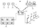
- FIG. 1 represents a citywide network in accordance with the principles of the invention
- FIG. 2 represents a network configuration in accordance with the principles of the invention
- FIG. 3 represents an exemplary interface in accordance with the principles of the invention
- FIG. 4 represents a method of providing direction in accordance with the principles of the invention
- FIG. 5A represents a process flow diagram of a method of operation of the system shown in FIG. 1 ;
- FIG. 5B represents a process flow diagram of processing performed at each pole in the system shown in FIG. 1 .
- FIG. 1 represents an exemplary citywide network system 100 comprising at least one central computer 130 (only one being illustrated for purposes of clarity) that is in communication with a plurality of sensor elements 110 and/or lighting elements 140 that are interconnected in a distribution network.
- Sensor elements 110 e.g. smoke sensor, air quality sensor, fire sensor, vision sensor, etc., are installed at places to detect various emergencies and to generate a signal that can be sent to central controller 130 for analysis and proper response.
- the at least one central computer 130 may be in communication with a city management system 120 that provides centralized control over a citywide management.
- Each of the at least one central controller 130 may provide information to the city management center regarding, for example, traffic, weather, accidents, emergencies, etc.
- the city management center 120 may provide information regarding large emergency information (e.g. earthquake) to the central controller 130 .
- central controller 130 will select one or multiple escape routes and control the multiple ceiling lights or multiple road lights to provide escape and evacuation information, as will be described more fully herein.
- the central controller 130 may also be in communication with a plurality of street lamps 150 or other similar infrastructure items (e.g., telephone poles) within a local region.
- the street lamps 150 may be arranged in a power distribution network that provides power to each of the street lamps 150 .
- Each street lamp 150 may be identified by an identification that corresponds to its position within the distribution network or may be identified by a physical location.
- the central controller 130 may provide the city management center 120 with information that may be used to control the local street lamps 150 through a corresponding central controller 130 .
- the city management center 120 may provide information to the central controllers 130 to monitor the status of the illumination lights 160 on the local street lamps 150 .
- the local street lamps 150 and associated illumination lights 160
- indoor lamps 140 may be used to provide directional information to users.
- the street lamps 150 (or other similar infrastructure), that line the sidewalks of a city's provide a convenient and simple method for providing directions to a user.
- the central controller 130 may receive information from the sensors 110 and/or city management center 120 and may send messages to indoor lighting 140 and/or illumination lights 160 included on corresponding street lamps 150 .
- Sensors 110 are used to directly detect emergency incidents (e.g., fire).
- City management center 120 can also directly send some emergency or potential emergency information (e.g., a disaster or an expected disaster) to the central controller 130 .
- the central control 130 may then react to the received information and control the lighting 160 on street lamps 150 to provide orderly direction movement.
- the central control 130 may control the indoor lighting system 140 and/or the outdoor lights 160 on the street lamp 150 to provide directional control to those in the local area to evacuate the area.
- FIG. 2 illustrates an exemplary configuration of a central computer (i.e., server) 130 in communication with each of a plurality of streetlamps (or lampposts) 150 , each street lamp 150 including an interface 200 , a user interface 220 and at least one signal light 240 .
- the signal light 240 may represent a light that is used to control traffic at an intersection, for example. Alternately, the signal light 240 may represent a post identification (e.g., physical location, data network identification, etc.).
- the interface 200 , the user interface 220 , signal light 240 and lights 160 on street lamps 150 may be powered from the electrical power supplied to the street lamp 150 in a conventional power network.
- the interface 200 may be powered by solar cells (not shown) that are attached to a corresponding streetlamp 150 .
- the server (central controller computer) 130 may be in wired or wireless communication with each of the plurality of streetlamps 150 over the network.
- Wireless protocols such as IEEE 802.11a/b/g/n (and other similar IEEE wireless standards) are well-known in the art and need not be discussed in detail herein.
- data signals may be provided between the central controller 130 and each streetlamp 150 over existing power line wired networks. Data over Power line networks are also known in the art and need not be discussed in detail herein.
- Each streetlamp 150 may be designated with a unique physical address that the central controller 130 may use to identify the streetlamp and the associated interface and with a data network identification that may be used to address or provide communication to the interface 200 and/or controllers within the streetlamp that control the operation of any illumination device attached to the street lamp 150 .
- FIG. 3 illustrates an exemplary interface 200 incorporated onto streetlamp 150 that provide information to a user.
- the interface may include a plurality of areas 240 , which are individually designated as 310 . . . 350 , herein, that are may be color coded that may be used to provide information (e.g., directions) to a user. Spare areas 360 may be included for future expansion.
- the color coding provides easy visual route identification, as the color progressively is displayed from one streetlamp 150 to a next streetlamp 150 .
- the interface 200 may also include a user interface area 220 that allows a user to input information, e.g., a desired destination.
- the user interface area may include one or more of well-known man-machine interfaces.
- the input user interface area 220 may include a keyboard to enter alphanumeric character or may include a pen type input to enter alphanumeric information or may include a voice recognition system that allows the user to input spoken words.
- Other similar type input device may be incorporated into the input area 220 to allow a user to input desired information.
- the interface 200 may include an audio output generator (not shown) that may provide audio output in response to the user's input (e.g., your destination is 3.2 miles west of this location) or may provide a large volume output in case of emergency (e.g., “emergency declared please follow light for evacuation”).
- an audio output generator not shown
- may provide audio output in response to the user's input e.g., your destination is 3.2 miles west of this location
- a large volume output in case of emergency e.g., “emergency declared please follow light for evacuation”.
- the central controller 130 determine routes of streetlamps 150 from the inputted location to the destination location, wherein the first streetlamp 150 in the route is associated with a current location and the last streetlamp 150 in the route is the streetlamp 150 closest to the destination.
- the route associated with the destination location is chosen so that adjacent streetlamps 150 may be used to provide directional information from the current location to the streetlamp 150 closest to the destination. If the desired destination is outside the local area, then the central controller 130 may determine the last streetlamp 150 to be in a next area and handoff the user to a next central controller.
- a directional control color may be selected that the user then follows from street lamp 150 to street lamp 150 until the user arrives at the desired destination.
- the control color may be implemented on alternating street lamps in order to provide for more users into the system.
- the directional colors may only be presented on two or three adjacent streetlamps and as the user follows the directional colors, the directional colors will progressively light on a next one or two streetlamps 150 as the user approaches the streetlamp showing the directional color.
- a predetermined walking speed may be considered in determining a time when to light the directional colors on a next one or two streetlamps.
- the user may be required to contact the light in order to acknowledge that the user is following the lighting system.
- having at least five colored displays 310 . . . 350 and two to-be-defined areas 360 allows up-to-seven individual users to be accommodated with the exemplary display.
- the use of the five colored displays is only for purposes of explaining the invention and is not to be considered limited to five elements or the colors shown.
- FIG. 3 one example of the user interface (UI) is shown.
- the user interface 200 there are signal lights that provide for directional control to predetermined destination locations.
- the first light is associated with a user after the user sets his destination successfully.
- the first light may represent a plurality of lights as shown in FIG. 2 .
- designated (predetermined) colors for merchants if the merchants want to advertise.
- the designated areas may be associated with specific events or activities (running events, meetings, etc.) that organizations may organize from time to time. The use of these areas within the interface may be a paid service that provides revenue for the local city to support the network being described.
- the user may contact a specific advertising merchant color and be provided directions to the advertising merchant without further input.
- many kinds of input method can be utilized, such as write pad or drop down list.
- the system can offer user two operation modes, i.e. a selection and a search.
- a user when a user wants to find a place (i.e., destination, remote location) they may go to the nearest lamppost 150 , input or search for their desired destination.
- the system may then randomly specify a color for their use and show the color on the UI 200 .
- the signal light starts to flash on a next lamppost 150 in sequence with this color for a short duration according to a walking distance to the next lamppost 150 .
- the user can follow the assigned color as it appears progressively on a next lamppost 150 (assigned in the route) to his destination place.
- the interface may include further audio commands to which the user may listen to.
- the interface may include an interface to receive communication from a mobile communication device (e.g., Bluetooth, Near Field Communication, cellular communication) and/or provide communication protocols that allow the directions to be transferred to the user's mobile phone or mobile communication device.
- a mobile communication device e.g., Bluetooth, Near Field Communication, cellular communication
- the interface may include an identification to which a user may “pair” their mobile device to the interface and provide an input through the mobile device.
- the destination instructions (or other information) may then be provided to the mobile device through the interface in addition to progressively lighting the directional lights, as previously described.
- the destination can also be set on the server 130 to enable special application.
- the system can enable government, organizations or individuals who are organizing activities to offer navigation to their guests.
- the special area on the interface may provide for a single input of a predetermined destination and the system operates to direct the user to the predetermined destination.
- the predetermined location can be associated with merchants to advertise and attract customers to their shops. These kinds of service may require that they be set on the server using administrator privilege.
- the service can be a paid service to which the merchants pay for the privilege of having a predetermined input location.
- the system may include pre-determined destinations that the user need only select the pre-determined destination to provide sufficient information to establish a route between the current lamppost 150 and the lamppost 150 closest to the included pre-determined destination.
- This aspect provides a further convenience to the user in that the user need not have to enter all the necessary information but only provide a single input.
- the input inputted by the user (which represents the destination location) from the specific lamppost 150 having a physical location identification and a data network identification is then used by the central controller 130 to determine a route to the desired destination.
- the route includes those lampposts 150 among a plurality of lampposts 150 within the control of the central controller 130 that may be used to direct the user from a current lamppost 150 to a next lamppost 150 .
- the user is assigned a color (visual indicator) that the user then progressively follows from the current lamppost 150 to a next lamppost 150 .
- the central controller 130 may determine the total route of lampposts 150 and may then provide communication to a next lamppost 150 at an appropriate time (based on a walking speed). Or the controller may determine a next lamppost 150 as the user approaches a current lamppost 150 and then provides communication to a dynamically determined next lamppost.
- the assignment of a next lamppost 150 in a next time interval is made dynamically.
- FIG. 4 illustrates exemplary displays, labeled (a), (b), (c) and (d) in which the display on the interface 200 may be progressively advanced in a directional pattern (i.e., in the direction of the arrows) to advise person within the view of the lights to follow in the same direction of travel.
- This form of progressive display to provide directional information may be valuable in an emergency situation wherein the local officials may direct persons within the emergency area out of the emergency area.
- the city management center 120 may provide to the central controller 130 a remote location outside an area deeming to be in an emergency condition.
- the central controller 130 may then determine a route from each streetlamp 150 to minimize a walking distance between the current streetlamp 150 and the remote location.
- the determined direction of travel provides safe evacuation of persons in the emergency area.
- the local central computer 130 (or servers) overrides the interface display so that an emergency direction of travel may be displayed on the streetlamps.
- the lamps 160 associated with the street lamps 150 may be flashed (turned on/off) at a known rate that provides for visual indication of a direction of travel.
- the lamps 160 may be progressively controlled, in turn, so that the turning on/off of the lamps 160 provides the illustration of motion and, hence, a direction of travel to evacuate the area.
- FIG. 4 may represent the ceiling lights 140 (see FIG. 1 ) of an indoor facility.
- the lighting control may be used to provide direction to persons within an area to follow the direction of lighting in order escape from the area.
- FIG. 4( a ) three lighting panel bays are allocated to form an arrow to indicate the direction of travel.
- the lights within a single lighting panel bay may be flashed at a rate that provides an indication of direction, as previously discussed.
- FIG. 4( d ) if multiple color lights are available, then lights may be flashed at a rate that provides for an indication of direction.
- the rate at which the lights are turned-on and -off will repeat so that the lighting does not walk away from the user. For example, as the turning on of lights is progressively advanced to a next light, after a predetermined number of lights have been progressively turned on/off, the pattern is again repeated from the original light. Thus, the lighting will provide the user within an illusion of direction as the lights are progressively advanced and the pattern repeated.
- Route discovery can be realized according to the current position and destination position.
- a route may be calculated using well-known navigation technique (e.g., GPS) and then the route is correlated to the route with the lighting infrastructure.
- GPS may provide a direct route to the final destination
- the central controller 130 translates the provided route to a route that is compensate with the street posts 150 in the local power network.
- the route could store the location of the lamppost 150 and select a next lamppost 150 on the route based on a predetermined walking direction and walking speed (i.e., estimated geographical position) or by the user acknowledging their presence at the lamppost 150 .
- the central controller 130 may maintain positions of each lamppost 150 based on their geographical position (e.g.
- each lamppost 150 is further identified by a unique address that identifies the lamppost 150 in a data communication network.
- the central computer 130 may determine a route based on already pre-determined routing paths that can be realized by directly using the lamp position location information to calculate an optimized route. For example, a destination location may be assigned to a particular streetlamp 150 location and when this destination location is input, a route from the current streetlamp 150 location may be determined.
- FIG. 5A illustrates an exemplary process operable in the central controller 130 in accordance with the principles of the invention.
- a current position and route is obtained for each color that is to be used, at block 510 . That is, in a multiple user system, as has been discussed, the routes for each assigned color are considered and the colors or visual indicators are appropriately provided to streetlamps 150 in the route assigned to that color.
- a next pole or streetlamp 150 within the route assigned by the color is determined or obtained.
- information regarding the color is sent to the next pole in the route associated with the assigned color.
- a determination is made regarding the number of colors being used on a next pole associated with each of the routes to which the next pole is assigned.
- a next pole in each route may be at a major intersection and a number of different routes converge on this pole at approximately the same time (or within a designated time interval).
- a repeat frequency of the blinking of the assigned color at the pole is adjusted so that each of the colors assigned to the pole are flashed for a predetermined number of times during the period the color is assigned to the pole.
- another route is calculated when a new user enters the system.
- the system waits proceeds to block 510 to continue the process of determining a next pole for each route currently in the system.
- FIG. 5B illustrates an exemplary processing at each next streetlamp 150 within a route of streetlamps 150 in accordance with the principles of the invention.
- information regarding the colors (associated with users) that is to be used is obtained from the central controller 130 at block 610 .
- the number of colors obtained determines a flash rate of each color during a period that the colors for the pole are to be flashed.
- a wait for the next time interval is made and then at block 640 the designated light colors are flashed at a rate based on the number of colors originally provided.
- Each streetlamp 150 operates their direction lighting system at an appropriate time in accordance with commands provided by the central controller 130 .
- the above-described methods according to the present invention can be implemented in hardware, firmware or as software or computer code that can be stored in a recording medium such as a CD ROM, an RAM, a floppy disk, a hard disk, or a magneto-optical disk or computer code downloaded over a network originally stored on a remote recording medium or a non-transitory machine readable medium and to be stored on a local recording medium, so that the methods described herein can be rendered in such software that is stored on the recording medium using a general purpose computer, or a special processor or in programmable or dedicated hardware, such as an ASIC or FPGA.
- a recording medium such as a CD ROM, an RAM, a floppy disk, a hard disk, or a magneto-optical disk or computer code downloaded over a network originally stored on a remote recording medium or a non-transitory machine readable medium and to be stored on a local recording medium, so that the methods described herein can be rendered in such software that is stored on the recording medium using a
- the computer, the processor, microprocessor controller or the programmable hardware include memory components, e.g., RAM, ROM, Flash, etc. that may store or receive software or computer code that when accessed and executed by the computer, processor or hardware implement the processing methods described herein.
- memory components e.g., RAM, ROM, Flash, etc.
- the execution of the code transforms the general purpose computer into a special purpose computer for executing the processing shown herein.
Landscapes
- Engineering & Computer Science (AREA)
- Radar, Positioning & Navigation (AREA)
- Remote Sensing (AREA)
- Physics & Mathematics (AREA)
- General Physics & Mathematics (AREA)
- Automation & Control Theory (AREA)
- Computer Networks & Wireless Communication (AREA)
- Navigation (AREA)
- Audible And Visible Signals (AREA)
- Circuit Arrangement For Electric Light Sources In General (AREA)
Priority Applications (1)
| Application Number | Priority Date | Filing Date | Title |
|---|---|---|---|
| US14/397,952 US9696159B2 (en) | 2012-05-03 | 2013-04-25 | Streetwise navigation system using infrastructure elements |
Applications Claiming Priority (3)
| Application Number | Priority Date | Filing Date | Title |
|---|---|---|---|
| US201261641943P | 2012-05-03 | 2012-05-03 | |
| PCT/IB2013/053264 WO2013164740A1 (en) | 2012-05-03 | 2013-04-25 | Streetwise navigation system using infrastructure elements |
| US14/397,952 US9696159B2 (en) | 2012-05-03 | 2013-04-25 | Streetwise navigation system using infrastructure elements |
Publications (2)
| Publication Number | Publication Date |
|---|---|
| US20150127251A1 US20150127251A1 (en) | 2015-05-07 |
| US9696159B2 true US9696159B2 (en) | 2017-07-04 |
Family
ID=48577182
Family Applications (1)
| Application Number | Title | Priority Date | Filing Date |
|---|---|---|---|
| US14/397,952 Expired - Fee Related US9696159B2 (en) | 2012-05-03 | 2013-04-25 | Streetwise navigation system using infrastructure elements |
Country Status (6)
| Country | Link |
|---|---|
| US (1) | US9696159B2 (enExample) |
| EP (1) | EP2845177A1 (enExample) |
| JP (1) | JP2015519650A (enExample) |
| CN (1) | CN104272359B (enExample) |
| RU (1) | RU2626028C2 (enExample) |
| WO (1) | WO2013164740A1 (enExample) |
Cited By (3)
| Publication number | Priority date | Publication date | Assignee | Title |
|---|---|---|---|---|
| US10417469B2 (en) | 2016-05-07 | 2019-09-17 | Morgan E. Davidson | Navigation using self-describing fiducials |
| US11036946B2 (en) | 2016-05-07 | 2021-06-15 | Canyon Navigation, LLC | Navigation using self-describing fiducials |
| US11828859B2 (en) | 2016-05-07 | 2023-11-28 | Canyon Navigation, LLC | Navigation using self-describing fiducials |
Families Citing this family (16)
| Publication number | Priority date | Publication date | Assignee | Title |
|---|---|---|---|---|
| EP3664583B1 (en) | 2013-03-18 | 2024-11-27 | Signify Holding B.V. | Methods and apparatus for information management and control of outdoor lighting networks |
| BE1022057B1 (nl) * | 2013-12-06 | 2016-02-11 | Televic Rail | Gepersonaliseerd begeleidingssysteem |
| JP6025267B2 (ja) * | 2014-06-20 | 2016-11-16 | 見治 西石垣 | サーベイ(眺望)型ナビゲーションシステム |
| DK3018977T3 (da) * | 2014-11-10 | 2019-06-17 | Schreder | Lygtenetværk |
| CN104807459A (zh) * | 2015-04-30 | 2015-07-29 | 吴博 | 一种室内导航系统及其导航方法 |
| JP6467312B2 (ja) * | 2015-07-31 | 2019-02-13 | 株式会社Nttドコモ | ナビゲーションシステム |
| CN106895836A (zh) * | 2015-12-17 | 2017-06-27 | 腾讯科技(深圳)有限公司 | 室内导航方法及装置 |
| JP2018055505A (ja) * | 2016-09-29 | 2018-04-05 | 富士通株式会社 | 案内システム、案内方法、案内プログラム及び照明装置 |
| CN108091088A (zh) * | 2016-11-21 | 2018-05-29 | 波士德媒体股份有限公司 | 住宅密集区域用智能标示系统 |
| DE102017205075A1 (de) * | 2017-03-27 | 2018-09-27 | Ford Global Technologies, Llc | Fahrzeugbasierte Steuerung einer Beleuchtung |
| US11297571B2 (en) * | 2017-07-21 | 2022-04-05 | Signify Holding B.V. | Controlling end nodes of a low-power wide area network |
| CN110440807A (zh) * | 2019-08-13 | 2019-11-12 | Oppo(重庆)智能科技有限公司 | 室内导航方法及装置、存储介质和电子设备 |
| CN111337035A (zh) * | 2020-02-27 | 2020-06-26 | 杭州勇电照明有限公司 | 一种智慧灯光路线指引方法 |
| US11614332B2 (en) * | 2020-12-17 | 2023-03-28 | Adobe Inc. | Systems for generating indications of traversable paths |
| CN113012595A (zh) * | 2021-03-22 | 2021-06-22 | 四川数字可见科技有限公司 | 紧急情况下的人群疏散系统 |
| KR102418566B1 (ko) * | 2021-12-22 | 2022-07-08 | 재단법인 지능형자동차부품진흥원 | 엣지 인프라 기반의 자율 주행 안전 제어 시스템 및 방법 |
Citations (22)
| Publication number | Priority date | Publication date | Assignee | Title |
|---|---|---|---|---|
| US5673039A (en) * | 1992-04-13 | 1997-09-30 | Pietzsch Ag | Method of monitoring vehicular traffic and of providing information to drivers and system for carring out the method |
| JP2003108052A (ja) | 2001-09-29 | 2003-04-11 | Keiji Matsuo | 防災用避難誘導案内表示機 |
| JP2005234768A (ja) | 2004-02-18 | 2005-09-02 | Sekisui Jushi Co Ltd | 避難誘導システム |
| US20060109113A1 (en) | 2004-09-17 | 2006-05-25 | Reyes Tommy D | Computer-enabled, networked, facility emergency notification, management and alarm system |
| JP2006233503A (ja) | 2005-02-23 | 2006-09-07 | Shin Sangyo Souzou Kenkyu Kiko | 歩行者誘導方法及び路面標示装置 |
| KR20070003423A (ko) | 2005-07-01 | 2007-01-05 | 서울메트로 | 지하철 승강장용 광고 및 비상 유도 장치 |
| CN1941028A (zh) | 2005-09-07 | 2007-04-04 | 马飞 | 一种地址定位及道路导向的方法 |
| JP2007156651A (ja) | 2005-12-01 | 2007-06-21 | Shomei:Kk | 誘導表示システム及び誘導表示装置 |
| WO2007090950A1 (fr) | 2006-02-08 | 2007-08-16 | Cooper Menvier Sas | Systeme d'affichage de chemin d'evacuation d'urgence |
| WO2009038557A1 (en) | 2007-09-19 | 2009-03-26 | United Technologies Corporation | Model-based egress support system |
| NL1035392C1 (nl) | 2008-05-06 | 2009-11-09 | Ledexpert B V | Straatrouteindicatiesysteem. |
| CN101639977A (zh) | 2008-07-28 | 2010-02-03 | 刘爱民 | 路标定位智能交通系统 |
| US20100102960A1 (en) | 2008-10-24 | 2010-04-29 | Altair Engineering, Inc. | Integration of led lighting control with emergency notification systems |
| US20100153003A1 (en) | 2007-06-12 | 2010-06-17 | Marcel Merkel | Information device, method for informing and/or navigating a person, and computer program |
| US20100259931A1 (en) | 2008-04-14 | 2010-10-14 | Digital Lumens, Inc. | Fixture with Intelligent Light Modules |
| DE102009031019A1 (de) | 2009-06-29 | 2010-12-30 | Siemens Aktiengesellschaft | System und Verfahren zur Bereitstellung von personalisierter Navigationsinformation |
| US20110022201A1 (en) | 2008-04-03 | 2011-01-27 | Koninklijke Philips Electronics N.V. | Method of guiding a user from an initial position to a destination in a public area |
| WO2011015975A2 (en) | 2009-08-05 | 2011-02-10 | Koninklijke Philips Electronics N.V. | Light guiding system and a method for controlling the same |
| EP2290324A1 (en) | 2009-08-28 | 2011-03-02 | Navteq North America, LLC | Method of operating a navigation system to provide route guidance |
| CN102103798A (zh) | 2011-02-10 | 2011-06-22 | 惠州Tcl移动通信有限公司 | 交通红绿灯状态信息提示系统及其方法 |
| US20110238299A1 (en) | 2010-03-24 | 2011-09-29 | Telenav, Inc. | Navigation system with route planning and method of operation thereof |
| US9046380B2 (en) * | 2010-11-30 | 2015-06-02 | Aisin Aw Co., Ltd. | Guiding apparatus, guiding method, and guiding program product |
Family Cites Families (5)
| Publication number | Priority date | Publication date | Assignee | Title |
|---|---|---|---|---|
| JPS548499A (en) * | 1977-06-22 | 1979-01-22 | Hitachi Shomei Kk | Escape guide device |
| JP2002108942A (ja) * | 2000-09-28 | 2002-04-12 | Mitsubishi Electric Corp | 情報提供システム |
| JP2004279986A (ja) * | 2003-03-18 | 2004-10-07 | Sanyo Electric Co Ltd | 内照式の表示灯 |
| JP2005092428A (ja) * | 2003-09-16 | 2005-04-07 | Toshiba Corp | トンネル照明制御装置 |
| JP4726648B2 (ja) * | 2006-02-20 | 2011-07-20 | 中国電力株式会社 | ナビゲーションシステムおよび位置情報提供サーバ |
-
2013
- 2013-04-25 EP EP13727377.7A patent/EP2845177A1/en not_active Withdrawn
- 2013-04-25 CN CN201380023235.6A patent/CN104272359B/zh not_active Expired - Fee Related
- 2013-04-25 WO PCT/IB2013/053264 patent/WO2013164740A1/en not_active Ceased
- 2013-04-25 RU RU2014148546A patent/RU2626028C2/ru not_active IP Right Cessation
- 2013-04-25 US US14/397,952 patent/US9696159B2/en not_active Expired - Fee Related
- 2013-04-25 JP JP2015509535A patent/JP2015519650A/ja not_active Ceased
Patent Citations (23)
| Publication number | Priority date | Publication date | Assignee | Title |
|---|---|---|---|---|
| US5673039A (en) * | 1992-04-13 | 1997-09-30 | Pietzsch Ag | Method of monitoring vehicular traffic and of providing information to drivers and system for carring out the method |
| JP2003108052A (ja) | 2001-09-29 | 2003-04-11 | Keiji Matsuo | 防災用避難誘導案内表示機 |
| JP2005234768A (ja) | 2004-02-18 | 2005-09-02 | Sekisui Jushi Co Ltd | 避難誘導システム |
| US20060109113A1 (en) | 2004-09-17 | 2006-05-25 | Reyes Tommy D | Computer-enabled, networked, facility emergency notification, management and alarm system |
| JP2006233503A (ja) | 2005-02-23 | 2006-09-07 | Shin Sangyo Souzou Kenkyu Kiko | 歩行者誘導方法及び路面標示装置 |
| KR20070003423A (ko) | 2005-07-01 | 2007-01-05 | 서울메트로 | 지하철 승강장용 광고 및 비상 유도 장치 |
| CN1941028A (zh) | 2005-09-07 | 2007-04-04 | 马飞 | 一种地址定位及道路导向的方法 |
| JP2007156651A (ja) | 2005-12-01 | 2007-06-21 | Shomei:Kk | 誘導表示システム及び誘導表示装置 |
| WO2007090950A1 (fr) | 2006-02-08 | 2007-08-16 | Cooper Menvier Sas | Systeme d'affichage de chemin d'evacuation d'urgence |
| US20100153003A1 (en) | 2007-06-12 | 2010-06-17 | Marcel Merkel | Information device, method for informing and/or navigating a person, and computer program |
| WO2009038557A1 (en) | 2007-09-19 | 2009-03-26 | United Technologies Corporation | Model-based egress support system |
| US20110022201A1 (en) | 2008-04-03 | 2011-01-27 | Koninklijke Philips Electronics N.V. | Method of guiding a user from an initial position to a destination in a public area |
| US20100259931A1 (en) | 2008-04-14 | 2010-10-14 | Digital Lumens, Inc. | Fixture with Intelligent Light Modules |
| NL1035392C1 (nl) | 2008-05-06 | 2009-11-09 | Ledexpert B V | Straatrouteindicatiesysteem. |
| CN101639977A (zh) | 2008-07-28 | 2010-02-03 | 刘爱民 | 路标定位智能交通系统 |
| US20100102960A1 (en) | 2008-10-24 | 2010-04-29 | Altair Engineering, Inc. | Integration of led lighting control with emergency notification systems |
| DE102009031019A1 (de) | 2009-06-29 | 2010-12-30 | Siemens Aktiengesellschaft | System und Verfahren zur Bereitstellung von personalisierter Navigationsinformation |
| WO2011015975A2 (en) | 2009-08-05 | 2011-02-10 | Koninklijke Philips Electronics N.V. | Light guiding system and a method for controlling the same |
| US9237634B2 (en) * | 2009-08-05 | 2016-01-12 | Koninklijke Philips N.V. | Light guiding system and a method for controlling the same |
| EP2290324A1 (en) | 2009-08-28 | 2011-03-02 | Navteq North America, LLC | Method of operating a navigation system to provide route guidance |
| US20110238299A1 (en) | 2010-03-24 | 2011-09-29 | Telenav, Inc. | Navigation system with route planning and method of operation thereof |
| US9046380B2 (en) * | 2010-11-30 | 2015-06-02 | Aisin Aw Co., Ltd. | Guiding apparatus, guiding method, and guiding program product |
| CN102103798A (zh) | 2011-02-10 | 2011-06-22 | 惠州Tcl移动通信有限公司 | 交通红绿灯状态信息提示系统及其方法 |
Non-Patent Citations (2)
| Title |
|---|
| "Synapse Intelligent Light System, Manage Lighting over the Internet for Commercial Buildings", 2010 Synapse Wireless. |
| Bhargava, Bharat et al "A Mobile-Cloud Pedestrian Crossing Guide for the Blind", 2011. |
Cited By (3)
| Publication number | Priority date | Publication date | Assignee | Title |
|---|---|---|---|---|
| US10417469B2 (en) | 2016-05-07 | 2019-09-17 | Morgan E. Davidson | Navigation using self-describing fiducials |
| US11036946B2 (en) | 2016-05-07 | 2021-06-15 | Canyon Navigation, LLC | Navigation using self-describing fiducials |
| US11828859B2 (en) | 2016-05-07 | 2023-11-28 | Canyon Navigation, LLC | Navigation using self-describing fiducials |
Also Published As
| Publication number | Publication date |
|---|---|
| US20150127251A1 (en) | 2015-05-07 |
| EP2845177A1 (en) | 2015-03-11 |
| JP2015519650A (ja) | 2015-07-09 |
| RU2014148546A (ru) | 2016-06-27 |
| CN104272359B (zh) | 2016-09-28 |
| RU2626028C2 (ru) | 2017-07-21 |
| WO2013164740A1 (en) | 2013-11-07 |
| CN104272359A (zh) | 2015-01-07 |
Similar Documents
| Publication | Publication Date | Title |
|---|---|---|
| US9696159B2 (en) | Streetwise navigation system using infrastructure elements | |
| JP6020872B1 (ja) | 分析システム及び分析方法 | |
| JP7101296B2 (ja) | 飛行体及び情報処理システム | |
| US9904286B2 (en) | Method and apparatus for providing adaptive transitioning between operational modes of an autonomous vehicle | |
| US10075812B1 (en) | Dynamic geo-fence size adjustment | |
| US10096246B2 (en) | Using lighting and other streetside devices to indicate parking space availability and navigation information | |
| CA2791992C (en) | Defining approach maps for traffic signal preemption controllers | |
| US20150330787A1 (en) | Systems, Methods and Software for Redirecting Blind Travelers Using Dynamic Wayfinding Orientation and Wayfinding Data | |
| US20080021632A1 (en) | Traffic Condition Report Device, System Thereof, Method Thereof, Program For Executing The Method, And Recording Medium Containing The Program | |
| US11403957B2 (en) | Method and apparatus for routing an aerial vehicle based on a relative noise impact | |
| US20130054134A1 (en) | Telematics apparatus for driving assistance, system of the same, and method of the same | |
| Liao | Using a smartphone application to support visually impaired pedestrians at signalized intersection crossings | |
| US10629068B2 (en) | Pedestrian walking routes using a smart traffic control system | |
| JP2015219070A (ja) | 情報提供システム、情報提供サーバ、情報提供方法、および、プログラム | |
| CN110194096B (zh) | 信息系统、信息处理方法以及存储介质 | |
| WO2019008755A1 (ja) | 情報処理システム及びそれに用いる情報処理システムインフラ及び情報処理方法 | |
| Prandi et al. | Enhancing sustainable mobility awareness by exploiting multi-sourced data: the case study of the Madeira Islands | |
| KR20100136591A (ko) | 차량 네비게이션의 주행 경로 서비스 방법 및 장치와 부가 서비스 제공 방법 및 그 장치 | |
| CN103185587A (zh) | 具有立体交叉侦测机制的导航系统及其操作方法 | |
| EP2950048A1 (en) | System and method for providing geographically based sound cues to a user of a mobile device | |
| KR102304920B1 (ko) | 옥외 조명, 이를 제어하기 위한 서버 장치 및 이들을 포함하는 조명 시스템과 그 제어 방법들 | |
| CN104871649A (zh) | 街道设备的操作状态的监测 | |
| JP2018180007A (ja) | 情報提供システム、情報提供方法、および、プログラム | |
| JP6758146B2 (ja) | 交通障害通知システム、交通障害通知サーバ、携帯通信端末、交通障害通知方法及び交通障害通知プログラム | |
| JP6659218B2 (ja) | 情報処理システム、情報処理プログラム、および、情報処理方法 |
Legal Events
| Date | Code | Title | Description |
|---|---|---|---|
| AS | Assignment |
Owner name: KONINKLIJKE PHILIPS ELECTRONICS N.V., NETHERLANDS Free format text: ASSIGNMENT OF ASSIGNORS INTEREST;ASSIGNORS:CHEN, HONGXIN;KNIBBE, ENGEL JOHANNES;GE, XIN;AND OTHERS;SIGNING DATES FROM 20130607 TO 20130611;REEL/FRAME:034071/0470 |
|
| AS | Assignment |
Owner name: PHILIPS LIGHTING HOLDING B.V., NETHERLANDS Free format text: ASSIGNMENT OF ASSIGNORS INTEREST;ASSIGNOR:KONINKLIJKE PHILIPS N.V.;REEL/FRAME:040060/0009 Effective date: 20160607 |
|
| STCF | Information on status: patent grant |
Free format text: PATENTED CASE |
|
| LAPS | Lapse for failure to pay maintenance fees |
Free format text: PATENT EXPIRED FOR FAILURE TO PAY MAINTENANCE FEES (ORIGINAL EVENT CODE: EXP.); ENTITY STATUS OF PATENT OWNER: LARGE ENTITY |
|
| STCH | Information on status: patent discontinuation |
Free format text: PATENT EXPIRED DUE TO NONPAYMENT OF MAINTENANCE FEES UNDER 37 CFR 1.362 |
|
| FP | Lapsed due to failure to pay maintenance fee |
Effective date: 20210704 |