US9605400B2 - Methods and apparatus for the installation of columns/piles - Google Patents
Methods and apparatus for the installation of columns/piles Download PDFInfo
- Publication number
- US9605400B2 US9605400B2 US13/260,745 US201013260745A US9605400B2 US 9605400 B2 US9605400 B2 US 9605400B2 US 201013260745 A US201013260745 A US 201013260745A US 9605400 B2 US9605400 B2 US 9605400B2
- Authority
- US
- United States
- Prior art keywords
- drilling machine
- drilling
- column
- pile
- lake
- Prior art date
- Legal status (The legal status is an assumption and is not a legal conclusion. Google has not performed a legal analysis and makes no representation as to the accuracy of the status listed.)
- Expired - Fee Related
Links
Images


Classifications
-
- E—FIXED CONSTRUCTIONS
- E02—HYDRAULIC ENGINEERING; FOUNDATIONS; SOIL SHIFTING
- E02D—FOUNDATIONS; EXCAVATIONS; EMBANKMENTS; UNDERGROUND OR UNDERWATER STRUCTURES
- E02D27/00—Foundations as substructures
- E02D27/32—Foundations for special purposes
- E02D27/52—Submerged foundations, i.e. submerged in open water
-
- E—FIXED CONSTRUCTIONS
- E02—HYDRAULIC ENGINEERING; FOUNDATIONS; SOIL SHIFTING
- E02D—FOUNDATIONS; EXCAVATIONS; EMBANKMENTS; UNDERGROUND OR UNDERWATER STRUCTURES
- E02D27/00—Foundations as substructures
- E02D27/32—Foundations for special purposes
- E02D27/42—Foundations for poles, masts or chimneys
-
- E—FIXED CONSTRUCTIONS
- E02—HYDRAULIC ENGINEERING; FOUNDATIONS; SOIL SHIFTING
- E02D—FOUNDATIONS; EXCAVATIONS; EMBANKMENTS; UNDERGROUND OR UNDERWATER STRUCTURES
- E02D13/00—Accessories for placing or removing piles or bulkheads, e.g. noise attenuating chambers
- E02D13/04—Guide devices; Guide frames
-
- E—FIXED CONSTRUCTIONS
- E02—HYDRAULIC ENGINEERING; FOUNDATIONS; SOIL SHIFTING
- E02D—FOUNDATIONS; EXCAVATIONS; EMBANKMENTS; UNDERGROUND OR UNDERWATER STRUCTURES
- E02D5/00—Bulkheads, piles, or other structural elements specially adapted to foundation engineering
- E02D5/22—Piles
- E02D5/24—Prefabricated piles
- E02D5/28—Prefabricated piles made of steel or other metals
- E02D5/285—Prefabricated piles made of steel or other metals tubular, e.g. prefabricated from sheet pile elements
-
- E—FIXED CONSTRUCTIONS
- E02—HYDRAULIC ENGINEERING; FOUNDATIONS; SOIL SHIFTING
- E02D—FOUNDATIONS; EXCAVATIONS; EMBANKMENTS; UNDERGROUND OR UNDERWATER STRUCTURES
- E02D7/00—Methods or apparatus for placing sheet pile bulkheads, piles, mouldpipes, or other moulds
- E02D7/22—Placing by screwing down
Definitions
- This invention relates to the methods of and apparatus for the installation of columns/piles and more particularly submerged columns/piles.
- the present invention is concerned with the installation of upstanding columns/piles that are intended to serve as supports for the mounting of installations above or below a water surface.
- Such installations can be of many forms or purposes, such as for example, supporting submerged water driven turbine installations, and/or wind driven turbine installations.
- the column/pile upon which it is mounted needs to be very firmly anchored in its upstanding position so as to be able to withstand forces that may be imposed upon the column/piles by water and air flows.
- a method of mounting one or more a column/pile in an upstanding position on a supporting surface formed by a lake, sea or river bed comprising the steps of lowering the column/pile to be installed from a support vessel into contact with the supporting surface, using the lower/toe end of the column/pile as a drill such upon rotation of the column/pile a bore is formed in the supporting surface into which the lower region of the column/pile is to be located and leaving the column/pile in situ in the thus formed bore after the completion of a drilling operation.
- a reverse fluid circulation is used during the drilling operation such that drill cutting debris is discharged into the water at the head of the column/pile by using a flow of compressed air derived from the support vessel by way of a flexible umbilical.
- a forward fluid circulation can be used during the drilling operation such that drill cutting debris is discharged into the water at the bed of the water within which drilling takes place using a flow of fluid supplied from the support vessel by way of a flexible umbilical.
- a submersible drilling machine is used for mounting one or more columns/piles to be inserted in the supporting surface, and deploying the machine from the surface support vessel so that it rests on the supporting surface, remotely operating from the support vessel one or more drilling mechanisms by way of one or more flexible umbilicals for delivering power to and for controlling the operation of the drilling machine, and following a required drilling operation recovering the drilling machine by the support vessel to leave one or more columns/piles upstanding from the supporting surface.
- a submersible drilling machine can incorporate one or more drilling mechanisms the machine being deployable with the aid of a surface support vessel so as to be able to rest on the lake, river, or sea bed as to be fully supportable by the lake, river or sea bed, means for remotely operating from the support vessel said one or more drilling mechanisms by way of one or more flexible umbilicals for delivering power to and for controlling the machine, and mains whereby following a required drilling operation the machine recoverable by the support vessel thereby to leave one or more columns/piles upstanding from the lake, river or sea bed.
- the machine incorporates telescopic legs or otherwise articulated members whereby the operational position of the drilling machine is positionally adjustable relative to the support surface in such manner as to level the machine so that its drilling mechanisms are able to produce a vertical bores in the supporting surface.
- the machine incorporates position adjustment actuators such as hydraulic cylinders, pneumatic cylinders, bags or bladders or the like.
- each column/pile to be installed is cylindrical it includes at its lower/toe end rock or soil cutters in such manner that on rotation of the column/pile about its longitudinal axis the column/pile effectively acts as a rotary drill, and wherein the machine incorporates means for rotating the column/pile thereby to perform a drilling operation.
- the machine includes means for enabling the drilling means of the machine to be positionally indexed from the site of a drilling operation to a site for the next following drilling operation without bodily moving the machine, the arrangement being such that a predetermined pattern of column/piles can be established without moving the entire machine.
- the drilling machine is recoverable to the support vessel whereby the machine can be equipped with a further column/pile and returned to a different location of the machine the arrangement being such as to allow a multiplicity of columns/piles to be installed in a predetermined pattern without moving the entire machine.
- the machine is provided with a plurality of drilling mechanisms whereby the drilling of a prearranged installation pattern of the columns/piles is facilitated.
- the machine includes means such as hydrofoils for utilizing the flow of water in the vicinity of the machine to create a net force that assists gravity in holding the machine onto the lake, river or sea bed.
- the machine incorporates telescopic legs or otherwise articulated members whereby the operational position of the drilling machine is positionally adjustable in such manner as to level the machine so that its drilling mechanisms are able to produce a vertical bore in the lake, river or sea bed.
- the machine incorporates position adjustment actuators such as hydraulic cylinders, pneumatic cylinders, bags or bladders or the like.
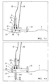
- FIGS. 1 a to 1 h schematically illustrate successive stages in the positioning and locating of a first embodiment of apparatus for installing and mounting a column/pile upon a lake, sea or river bed.
- FIGS. 2 a and 2 b schematically illustrate a second embodiment of apparatus for installing and mounting a column/pile upon a lake, sea or river bed and
- FIG. 3 schematically illustrates a further embodiment of the apparatus for installing and mounting a column/pile upon a lake, sea or river bed.
- FIG. 1 a This Figure schematically illustrates a surface vessel 1 positioned in the vicinity of a location 2 of a sea/river bed 3 at which it is required to install an upstanding columns/pile 4 .
- the surface vessel 1 carries a column/pile 4 or several columns/piles 4 to be mounted in the sea/river bed 3 .
- such columns/piles are shown as being located at the stern end 5 of the vessel 1 .
- a derrick/crane installation 6 is located at the stem end 7 of the vessel supports a drilling machine 8 which incorporates a main platform section 9 mounting a plurality of telescopic legs 10 having profiled feet 11 that are intended to engage with the lake, sea or river bed 3 in the vicinity of the required location 2 .
- the drilling machine 8 is suspended for deployment into the water by means of a cable 12 and an associated winch assembly 13 .
- a column/pile 4 to be installed in the sea/river bed 3 is shown as being vertically positioned on the drilling machine 8 in its drilling position. In other words a column/pile 4 is pre-installed on the drilling machine 8 .
- the drilling machine 8 incorporates equipment for rotating the column/pile 4 carried thereby in order to carry out an installing operation. Arrangements for operating the drilling machine are provided in the form of flexible umbilical connections 15 , 16 operationally connected between the drilling machine 8 and associated control equipment (not shown) provided on the vessel 1 .
- the vessel 1 is maintained in its required operational position throughout a drilling operation by appropriate vessel positioning arrangements such as mooring cables and/or a dynamic vessel positioning systems (not shown)
- the drilling machine 8 would be positioned by the winch assembly 13 inboard of the vessel and once the required position 2 of the lake, sea or river bed 3 at which it is required to install the column/pile 4 has been reached the drilling machine 8 is moved by the winch assembly 13 to a positional setting at in which it can be lowered by the winch assembly 13 down to the sea machine bed 3 to the position as shown in FIG. 1 b.
- This leveling operation is discussed in relation to FIG. 1 c from which it will be noted that the drilling rig platform 9 has been set to a horizontal operational setting by appropriate height adjustment of the legs 10 together with any lateral positional adjustment to position the column/pile above the lake, sea or riverbed location 2 at which it is to be positioned and to ensure that the platform 9 is positionally stable.
- this positional adjustment of the drilling machine 8 may be effected by using hydraulic or electrical actuators (not shown) controlled from the vessel 1 by way of the umbilical connections 15 / 16 .
- the socket/bore 17 for receiving the column/pile is created by a rotary drilling operation using the lower/toe end 18 of the column/pile 4 as a drill bit.
- the lower end/toe 18 of the column/pile 4 is equipped with cutters 19 regarded as being suitable for the expected lake, sea or river bed conditions.
- the required rotational drilling torque is applied to the column/pile by a rotary drill drive.
- the required force necessary to move the column/pile downwards during the drilling rotation is supplied by the weight of the column/pile. If, in practice, this is found not to be sufficient the column/pile can be ballasted by the application of weight to the column/pile. If necessary, additional force can be obtained from hydraulic cylinders 21 .
- a guide tube 22 within which the column/pile 4 is located whilst on the drilling machine serves to maintain the column/pile 4 in a vertical position during the drilling operation.
- power for the drilling operation and the control of the actual drilling operation is derived from the vessel 1 by way of the umbilicals 15 and 16 .
- other services to the column/pile such as compressed air for the removal of drilling debris/cuttings can be supplies by way of the umbilicals 15 and 16 between the vessel 1 and the drilling machine 8 .
- FIG. 1 d this Figure schematically illustrates the stage at which the column/pile 4 has been advanced to a required depth in the lake, sea or river bed 3 .
- the annulus 17 A that has been produced by the drilling operation around inserted part of the column/pile 4 needs to be filled with grout to ensure that the column/pile 4 is firmly secured in position.
- This grout can be mixed on the vessel 1 and can be fed to the annulus 17 A by the umbilical 15 used for the pumping in of air.
- the umbilicals 15 , 16 can be released and recovered to the surface vessel.
- the torque drive and associated hydraulic cylinders 21 can be moved to the required location for the next column/pile 4 to be inserted in the lake, sea or river bed.
- This displacement can be achieved in many different ways, for example, by using a yaw drive to move the drilling unit 20 to a new position as is illustrated in FIG. 1 e .
- a new column/pile 4 can then be lowered into the guide tube 22 from the vessel 1 .
- the first column/pile 4 to be installed could be separate from the deploying of the drilling machine 8 to the lake, sea or river bed. In this case the drilling machine can be deployed without the column/pile 4 being in place In particular as may be seen from FIG.
- FIG. 1 e this is shown as being located to the right of the position shown in FIGS. 1 c and 1 d .
- the guide tube 22 and associated drill unit 20 can be displaced relative to the drilling machine platform 9 by a drive unit 23 which is such as to displace the guide tube 22 to a selected one of a number of possible operational positions relative to the platform 9 .
- FIG. 1 f illustrates an installation stage in which the first column/pile 4 has been inserted and the guide tube 22 has been moved to the next required position and the next column/pile 4 to be mounted in the lake, sea or river bed has been installed in a manner as discussed in relation to FIGS. 1 c and 1 d and grout has been or is being inserted into the annulus 17 produced in the lake, sea or river bed by the drilling operation.
- FIG. 1 g illustrates very schematically the mounting of a turbine and rotor installation 25 being mounted to the columns/piles previously inserted as herein before described in relation to the previously discussed FIGS. 1 a to 1 g.
- FIGS. 2 a and 2 b illustrate a second embodiment of a drilling machine apparatus 35 in which the platform of the previous Figures is effectively replaced by arrangement of sealed ballast tanks 26 which when filled with air are able to float in water so that they drilling machine can be moved to a required drilling position by being towed by the control vessel 1 .
- the ballast tanks 26 are partially flooded with water to an extent that the ballast tanks and the associated drilling machine 8 exhibits a slightly negative buoyancy so that the drilling machine 8 can be lowered to the lake, sea or river bed 3 by the winch assembly 13 .
- the drilling machine 8 is at the lake, sea or river bed 3 and the drilling machine 8 has been leveled so the drilling machine platform 9 is horizontal and the guide tube 22 is vertical the ballast tanks 26 are fully flooded with water thereby maximizing the submerged weight of the drilling machine 8 and therefore its frictional engagement with the lake, sea or river bed 3 .
- the water is exhausted from the ballast tanks 26 to cause the drilling machine 8 to be readily liftable back to the vessel 1 .
- FIG. 3 schematically illustrates a further embodiment of a drilling machine 8 which is such that weight required to stabilize the drilling machine whilst on a lake, sea or river bed 3 is reduced.
- the machine is provided with positionally adjustable hydrofoils settable such that down force is produced by tide or river flows, thereby increasing the requisite friction between the machine feet 11 and the lake, sea or bed 3 thereby helping to counteract water flow drag on the drilling machine.
Landscapes
- Engineering & Computer Science (AREA)
- Structural Engineering (AREA)
- Life Sciences & Earth Sciences (AREA)
- General Life Sciences & Earth Sciences (AREA)
- Mining & Mineral Resources (AREA)
- Paleontology (AREA)
- Civil Engineering (AREA)
- General Engineering & Computer Science (AREA)
- Earth Drilling (AREA)
- Placing Or Removing Of Piles Or Sheet Piles, Or Accessories Thereof (AREA)
- Supports For Plants (AREA)
Applications Claiming Priority (3)
| Application Number | Priority Date | Filing Date | Title |
|---|---|---|---|
| GBGB0905663.1A GB0905663D0 (en) | 2009-04-01 | 2009-04-01 | Methods of and apparatus for the installation of columns/piles |
| GB0905663.1 | 2009-04-01 | ||
| PCT/GB2010/000611 WO2010112832A1 (en) | 2009-04-01 | 2010-03-29 | Methods and apparatus for the installation of columns / piles |
Publications (2)
| Publication Number | Publication Date |
|---|---|
| US20120177447A1 US20120177447A1 (en) | 2012-07-12 |
| US9605400B2 true US9605400B2 (en) | 2017-03-28 |
Family
ID=40672144
Family Applications (1)
| Application Number | Title | Priority Date | Filing Date |
|---|---|---|---|
| US13/260,745 Expired - Fee Related US9605400B2 (en) | 2009-04-01 | 2010-03-29 | Methods and apparatus for the installation of columns/piles |
Country Status (13)
| Country | Link |
|---|---|
| US (1) | US9605400B2 (ko) |
| EP (1) | EP2414594B2 (ko) |
| JP (1) | JP5591319B2 (ko) |
| KR (1) | KR101743424B1 (ko) |
| CN (1) | CN102449240B (ko) |
| AU (1) | AU2010231220B2 (ko) |
| CA (1) | CA2757365C (ko) |
| CL (1) | CL2011002440A1 (ko) |
| DK (1) | DK2414594T3 (ko) |
| GB (2) | GB0905663D0 (ko) |
| NZ (1) | NZ596103A (ko) |
| RU (1) | RU2011144146A (ko) |
| WO (1) | WO2010112832A1 (ko) |
Cited By (2)
| Publication number | Priority date | Publication date | Assignee | Title |
|---|---|---|---|---|
| US10968591B2 (en) | 2016-09-30 | 2021-04-06 | Ihc Iqip Uk Ltd. | Pile guide comprising a base frame and a guide member |
| US20210229782A1 (en) * | 2020-01-27 | 2021-07-29 | Other Lab, Llc | Vehicle for installing anchors in an underwater substrate |
Families Citing this family (29)
| Publication number | Priority date | Publication date | Assignee | Title |
|---|---|---|---|---|
| DK2322724T3 (da) * | 2009-11-17 | 2012-05-21 | Bauer Maschinen Gmbh | Undervandsboreindretning og fremgangsmåde til anbringelse af et rørformet funderingselement i havbunden |
| GB2473683B (en) * | 2010-01-05 | 2012-01-11 | Fast Frames Uk Ltd | Method and apparatus for driving a pile into a substrate |
| EP2588703B1 (en) * | 2010-06-30 | 2018-08-01 | Marl Technologies Inc. | Remotely operable underwater drilling system and drilling method |
| DK2402511T3 (en) * | 2010-07-02 | 2016-06-06 | Ihc Holland Ie Bv | Template for and method of installation of a plurality of foundation members in an underwater land formation. |
| GB2488839B (en) * | 2011-03-11 | 2015-10-28 | Mclaughlin & Harvey Ltd | A system and method for the installations of underwater foundations |
| EP2527539B1 (de) | 2011-05-27 | 2013-09-11 | BAUER Maschinen GmbH | Unterwasser-Bohranordnung und Verfahren zum Einbringen eines Gründungselementes in einen Gewässergrund |
| EP2532790B1 (de) | 2011-06-10 | 2013-08-21 | Bauer Spezialtiefbau GmbH | Verfahren zum Herstellen eines Unterwasser-Gründungselementes, Justierkopf für ein Unterwasser-Gründungselement und Unterwasser-Arbeitsanordnung |
| EP2562348B1 (de) | 2011-08-23 | 2017-10-04 | BAUER Maschinen GmbH | Unterwasser-Bohranordnung und Verfahren zum Erstellen einer Bohrung |
| EP2562310B1 (de) | 2011-08-23 | 2016-07-20 | BAUER Maschinen GmbH | Unterwasser-Bohranordnung und Verfahren zum Erstellen einer Bohrung in einem Gewässergrund |
| EP2562347B1 (de) | 2011-08-23 | 2019-05-22 | BAUER Maschinen GmbH | Unterwasser-arbeitsanordnung und verfahren zu ihrer verankerung |
| DK2574698T3 (da) * | 2011-09-30 | 2014-05-05 | Siemens Ag | Fremgangsmåde og indretning til at drive en flerhed af pæle i havbunden |
| GB2496412B (en) * | 2011-11-10 | 2016-02-17 | Tidal Generation Ltd | Installing underwater structures |
| NL2008279C2 (en) * | 2012-02-13 | 2013-08-14 | Ihc Holland Ie Bv | A template for and method of installing a plurality of foundation elements in an underwater ground formation. |
| NL2009610C2 (en) * | 2012-10-11 | 2014-04-14 | Ihc Sea Steel Ltd | Pile driving guide. |
| US20140234031A1 (en) * | 2013-02-15 | 2014-08-21 | 9187-8850 Québec Inc. | Method, kit and system for injecting grout into a borehole, method of deploying a tube into a borehole for grout injection and leader for use in a grout injection system |
| NL2010375C2 (en) | 2013-02-28 | 2014-09-01 | Ihc Sea Steel Ltd | Pile driving guide. |
| US10100482B2 (en) | 2013-08-28 | 2018-10-16 | Mhi Vestas Offshore Wind A/S | Method of installing an offshore foundation and template for use in installing an offshore foundation |
| CN106978982A (zh) * | 2016-01-15 | 2017-07-25 | 谢靖宇 | 一种桥梁工程泥浆处理装置 |
| CN106522256B (zh) * | 2016-10-31 | 2018-07-10 | 王燏斌 | 一种螺旋凹槽筒形基础及制造方法和施工方法 |
| CN106522255A (zh) * | 2016-10-31 | 2017-03-22 | 王燏斌 | 底部带刀的单壁螺旋筒形基础及其施工法 |
| KR200488881Y1 (ko) | 2016-11-03 | 2019-04-01 | 서현두 | 지주설치장치 |
| CN106761407A (zh) * | 2016-11-29 | 2017-05-31 | 中国地质大学(武汉) | 一种水上勘探装置 |
| WO2018129471A1 (en) * | 2017-01-06 | 2018-07-12 | Nelson Charles W | Modular offshore wind turbine foundation and modular substructure with suction caissons |
| KR102020108B1 (ko) * | 2017-07-25 | 2019-09-09 | 현대건설주식회사 | 해저 케이블 설치가 용이한 조류발전장치 시공 시스템 |
| DE102018104328A1 (de) * | 2018-02-26 | 2019-08-29 | Overdick Gmbh & Co. Kg | Offshore-Plattform mit wenigstens einem Rammpfahl |
| FR3084380B1 (fr) * | 2018-07-30 | 2020-10-23 | Saipem Sa | Procede d'installation d'un pieu metallique tubulaire dans un sol rocheux |
| CN109374388B (zh) * | 2018-11-23 | 2020-12-25 | 东南大学 | 用于模型桩受荷试验中准确定位模型桩位置的装置及其使用方法 |
| CN110250046A (zh) * | 2019-07-08 | 2019-09-20 | 自然资源部海洋减灾中心 | 一种海底安装珊瑚培育装置的方法 |
| KR102501321B1 (ko) * | 2021-05-20 | 2023-02-21 | 이현후 | 해상 바닥 설치용 바이브레이션 말뚝 설치장치 |
Citations (18)
| Publication number | Priority date | Publication date | Assignee | Title |
|---|---|---|---|---|
| US3328969A (en) * | 1964-11-02 | 1967-07-04 | Kaiser Steel Corp | Apparatus for driving piles |
| US3741320A (en) * | 1971-07-12 | 1973-06-26 | Atlas Copco Ab | Subsea drilling assembly |
| GB1333472A (en) | 1971-02-01 | 1973-10-10 | Shell Int Research | Method of anchoring an object buried in the bottom material beneath a body of water |
| US3891037A (en) * | 1972-12-26 | 1975-06-24 | Dale E Well | Remotely operated seafloor coring and drilling method and system |
| US4181455A (en) | 1978-05-17 | 1980-01-01 | Tad Stanwick | Apparatus for generating rotary power in a deep-sea environment |
| WO1986001556A1 (en) | 1984-09-05 | 1986-03-13 | Kahlman Innovation Ab | Submarine element driving means |
| JPS6198818A (ja) | 1984-10-19 | 1986-05-17 | Shiraishi:Kk | 回転圧入式鋼管杭 |
| US4657092A (en) * | 1985-07-17 | 1987-04-14 | J & F Oil Tools, Inc. | Circulation reversing tool |
| JPS62291324A (ja) | 1986-06-10 | 1987-12-18 | Tokyu Constr Co Ltd | 杭体の建込み方法およびその建込み装置 |
| EP0301114A1 (de) | 1987-07-28 | 1989-02-01 | Menck Gmbh | Verfahren zum Eintreiben von Rammteilen unter Wasser |
| US5244312A (en) | 1991-12-29 | 1993-09-14 | Conoco Inc. | Pile supported drilling template |
| RU2071531C1 (ru) | 1993-11-04 | 1997-01-10 | Индивидуальное частное предприятие "Гео Инструментс" | Свая морской нефтегазовой платформы |
| CN1308001A (zh) | 2001-03-22 | 2001-08-15 | 上海交通大学 | 深海打桩装置 |
| WO2002035013A1 (de) | 2000-10-27 | 2002-05-02 | Vibroflotation B.V. | Vorrichtung und verfahren zur erzeugung von materialsäulen im boden von gewässern |
| EP1493868A1 (en) | 2003-07-03 | 2005-01-05 | Presign B.V. | Method for placing an offshore jacket on the seabed |
| US20080053358A1 (en) * | 2002-09-05 | 2008-03-06 | Alan Owen | Apparatus for controlling underwater based equipment |
| US7380614B1 (en) * | 2007-05-11 | 2008-06-03 | Williamson & Associates, Inc. | Remotely operated water bottom based drilling system using cable for auxiliary operations |
| GB2448358A (en) | 2007-04-12 | 2008-10-15 | Tidal Generation Ltd | Installation of underwater ground anchorages |
Family Cites Families (12)
| Publication number | Priority date | Publication date | Assignee | Title |
|---|---|---|---|---|
| DE2249281A1 (de) † | 1972-10-07 | 1974-04-18 | Gruen & Bilfinger Ag | Verlorene vollbohrkrone mit freischnittschneide |
| DE2300212A1 (de) † | 1973-01-03 | 1974-07-11 | Heinrich Stade | Verfahren und vorrichtung zur herstellung von pfahlgruendungen unter verwendung von fertigbetonpfaehlen |
| GB1552162A (en) † | 1977-11-17 | 1979-09-12 | Parry P J | Marine structures |
| NL8102327A (nl) † | 1981-05-12 | 1982-12-01 | Fundamentum Bv | Werkwijze voor het vervaardigen van een fundatiepaal alsmede een daarbij toe te passen buis. |
| NL189365C (nl) † | 1984-04-09 | 1993-03-16 | Fundex Naamloze Vennootschap | Grondverdringingsboor, alsmede werkwijze voor het vormen van een fundatiepaal in de grond onder toepassing van die grondverdringingsboor. |
| JPS6138090A (ja) * | 1984-07-31 | 1986-02-24 | 三菱重工業株式会社 | 海底着底式構造物 |
| JP2751007B2 (ja) * | 1994-06-24 | 1998-05-18 | 首都高速道路公団 | 水中歩行式浚渫方法および浚渫機 |
| DE19702137A1 (de) † | 1997-01-22 | 1998-07-23 | Fundex N V | Erdverdrängungsbohrer |
| DE19743415A1 (de) † | 1997-10-01 | 1999-06-10 | Josef Dipl Ing Behrens | Selbstbohrender Betonpfahl |
| JP3790452B2 (ja) * | 2001-08-03 | 2006-06-28 | 三菱重工業株式会社 | ジャケット構造体 |
| GB0809521D0 (en) * | 2008-05-24 | 2008-07-02 | Marine Current Turbines Ltd | Installation of structures in water |
| DK2322724T3 (da) † | 2009-11-17 | 2012-05-21 | Bauer Maschinen Gmbh | Undervandsboreindretning og fremgangsmåde til anbringelse af et rørformet funderingselement i havbunden |
-
2009
- 2009-04-01 GB GBGB0905663.1A patent/GB0905663D0/en not_active Ceased
-
2010
- 2010-03-29 JP JP2012502764A patent/JP5591319B2/ja not_active Expired - Fee Related
- 2010-03-29 AU AU2010231220A patent/AU2010231220B2/en not_active Ceased
- 2010-03-29 WO PCT/GB2010/000611 patent/WO2010112832A1/en active Application Filing
- 2010-03-29 DK DK10715572.3T patent/DK2414594T3/en active
- 2010-03-29 CN CN201080022658.2A patent/CN102449240B/zh not_active Expired - Fee Related
- 2010-03-29 RU RU2011144146/03A patent/RU2011144146A/ru unknown
- 2010-03-29 CA CA2757365A patent/CA2757365C/en not_active Expired - Fee Related
- 2010-03-29 KR KR1020117025827A patent/KR101743424B1/ko active IP Right Grant
- 2010-03-29 GB GB1005212.4A patent/GB2469190B/en not_active Expired - Fee Related
- 2010-03-29 US US13/260,745 patent/US9605400B2/en not_active Expired - Fee Related
- 2010-03-29 NZ NZ596103A patent/NZ596103A/en not_active IP Right Cessation
- 2010-03-29 EP EP10715572.3A patent/EP2414594B2/en active Active
-
2011
- 2011-09-30 CL CL2011002440A patent/CL2011002440A1/es unknown
Patent Citations (22)
| Publication number | Priority date | Publication date | Assignee | Title |
|---|---|---|---|---|
| US3328969A (en) * | 1964-11-02 | 1967-07-04 | Kaiser Steel Corp | Apparatus for driving piles |
| GB1333472A (en) | 1971-02-01 | 1973-10-10 | Shell Int Research | Method of anchoring an object buried in the bottom material beneath a body of water |
| US3741320A (en) * | 1971-07-12 | 1973-06-26 | Atlas Copco Ab | Subsea drilling assembly |
| US3891037A (en) * | 1972-12-26 | 1975-06-24 | Dale E Well | Remotely operated seafloor coring and drilling method and system |
| US4181455A (en) | 1978-05-17 | 1980-01-01 | Tad Stanwick | Apparatus for generating rotary power in a deep-sea environment |
| WO1986001556A1 (en) | 1984-09-05 | 1986-03-13 | Kahlman Innovation Ab | Submarine element driving means |
| JPS6198818A (ja) | 1984-10-19 | 1986-05-17 | Shiraishi:Kk | 回転圧入式鋼管杭 |
| US4657092A (en) * | 1985-07-17 | 1987-04-14 | J & F Oil Tools, Inc. | Circulation reversing tool |
| JPS62291324A (ja) | 1986-06-10 | 1987-12-18 | Tokyu Constr Co Ltd | 杭体の建込み方法およびその建込み装置 |
| US4818149A (en) | 1987-07-28 | 1989-04-04 | Bomag-Menck Gmbh | Method of and a drive unit for driving ramming parts under water |
| EP0301114A1 (de) | 1987-07-28 | 1989-02-01 | Menck Gmbh | Verfahren zum Eintreiben von Rammteilen unter Wasser |
| US4872514A (en) | 1987-07-28 | 1989-10-10 | Bomag-Menck Gmbh | Drive unit for driving ramming parts under water |
| US5244312A (en) | 1991-12-29 | 1993-09-14 | Conoco Inc. | Pile supported drilling template |
| RU2071531C1 (ru) | 1993-11-04 | 1997-01-10 | Индивидуальное частное предприятие "Гео Инструментс" | Свая морской нефтегазовой платформы |
| WO2002035013A1 (de) | 2000-10-27 | 2002-05-02 | Vibroflotation B.V. | Vorrichtung und verfahren zur erzeugung von materialsäulen im boden von gewässern |
| US20040074560A1 (en) | 2000-10-27 | 2004-04-22 | Alexander Degen | Device and method for producing columns of materials in the ground of bodies of water |
| CN1308001A (zh) | 2001-03-22 | 2001-08-15 | 上海交通大学 | 深海打桩装置 |
| US20080053358A1 (en) * | 2002-09-05 | 2008-03-06 | Alan Owen | Apparatus for controlling underwater based equipment |
| EP1493868A1 (en) | 2003-07-03 | 2005-01-05 | Presign B.V. | Method for placing an offshore jacket on the seabed |
| GB2448358A (en) | 2007-04-12 | 2008-10-15 | Tidal Generation Ltd | Installation of underwater ground anchorages |
| US20100119309A1 (en) | 2007-04-12 | 2010-05-13 | Tidal Generation Limited | Installation of underwater ground anchorages |
| US7380614B1 (en) * | 2007-05-11 | 2008-06-03 | Williamson & Associates, Inc. | Remotely operated water bottom based drilling system using cable for auxiliary operations |
Cited By (3)
| Publication number | Priority date | Publication date | Assignee | Title |
|---|---|---|---|---|
| US10968591B2 (en) | 2016-09-30 | 2021-04-06 | Ihc Iqip Uk Ltd. | Pile guide comprising a base frame and a guide member |
| US20210229782A1 (en) * | 2020-01-27 | 2021-07-29 | Other Lab, Llc | Vehicle for installing anchors in an underwater substrate |
| US11565779B2 (en) * | 2020-01-27 | 2023-01-31 | Other Lab, Llc | Vehicle for installing anchors in an underwater substrate |
Also Published As
| Publication number | Publication date |
|---|---|
| CN102449240B (zh) | 2017-05-03 |
| US20120177447A1 (en) | 2012-07-12 |
| AU2010231220A1 (en) | 2011-10-27 |
| NZ596103A (en) | 2014-02-28 |
| KR20120014135A (ko) | 2012-02-16 |
| AU2010231220B2 (en) | 2016-05-19 |
| CA2757365A1 (en) | 2010-10-07 |
| GB0905663D0 (en) | 2009-05-13 |
| CN102449240A (zh) | 2012-05-09 |
| EP2414594B2 (en) | 2020-02-26 |
| GB201005212D0 (en) | 2010-05-12 |
| JP2012522912A (ja) | 2012-09-27 |
| GB2469190A (en) | 2010-10-06 |
| CL2011002440A1 (es) | 2012-04-20 |
| WO2010112832A1 (en) | 2010-10-07 |
| JP5591319B2 (ja) | 2014-09-17 |
| GB2469190B (en) | 2015-01-28 |
| EP2414594A1 (en) | 2012-02-08 |
| CA2757365C (en) | 2016-11-08 |
| DK2414594T3 (en) | 2016-06-06 |
| EP2414594B1 (en) | 2016-05-11 |
| KR101743424B1 (ko) | 2017-06-15 |
| RU2011144146A (ru) | 2013-05-10 |
Similar Documents
| Publication | Publication Date | Title |
|---|---|---|
| US9605400B2 (en) | Methods and apparatus for the installation of columns/piles | |
| CA2637305C (en) | Gravity foundations for tidal stream turbines | |
| CA2684068C (en) | Installation of underwater ground anchorages | |
| CA2626104C (en) | Installation of underwater anchorages | |
| GB2460172A (en) | Installation of a pile in the seabed using a guide structure | |
| EP1945862B1 (en) | Installation of underwater anchorages | |
| EP2261425A1 (en) | Hybrid offshore large pile - gravity foundation for constructions, and installation method therefor | |
| WO2012030220A1 (en) | Method for introducing a hollow elongated structure into a water bottom | |
| JP2019060227A (ja) | ジャケット構造体の構築方法 |
Legal Events
| Date | Code | Title | Description |
|---|---|---|---|
| AS | Assignment |
Owner name: MARINE CURRENT TURBINES LIMITED, UNITED KINGDOM Free format text: ASSIGNMENT OF ASSIGNORS INTEREST;ASSIGNOR:MONTAGUE, RICHARD;REEL/FRAME:033402/0680 Effective date: 20140630 Owner name: MARINE CURRENT TURBINES LIMITED, UNITED KINGDOM Free format text: ASSIGNMENT OF ASSIGNORS INTEREST;ASSIGNOR:FRAENKEL, PETER LEONARD;REEL/FRAME:033402/0478 Effective date: 20140610 |
|
| AS | Assignment |
Owner name: BAUER MASCHINEN GMBH, GERMANY Free format text: CONVEYANCE OF RIGHTS;ASSIGNOR:MARINE CURRENT TURBINES LIMITED;REEL/FRAME:034150/0529 Effective date: 20140919 Owner name: MARINE CURRENT TURBINES LIMITED, UNITED KINGDOM Free format text: CONVEYANCE OF RIGHTS;ASSIGNOR:MARINE CURRENT TURBINES LIMITED;REEL/FRAME:034150/0529 Effective date: 20140919 |
|
| STCF | Information on status: patent grant |
Free format text: PATENTED CASE |
|
| FEPP | Fee payment procedure |
Free format text: MAINTENANCE FEE REMINDER MAILED (ORIGINAL EVENT CODE: REM.); ENTITY STATUS OF PATENT OWNER: LARGE ENTITY |
|
| LAPS | Lapse for failure to pay maintenance fees |
Free format text: PATENT EXPIRED FOR FAILURE TO PAY MAINTENANCE FEES (ORIGINAL EVENT CODE: EXP.); ENTITY STATUS OF PATENT OWNER: LARGE ENTITY |
|
| STCH | Information on status: patent discontinuation |
Free format text: PATENT EXPIRED DUE TO NONPAYMENT OF MAINTENANCE FEES UNDER 37 CFR 1.362 |
|
| FP | Lapsed due to failure to pay maintenance fee |
Effective date: 20210328 |