US9592621B2 - Equipment for high speed transversal perforations of variable lengths on continuous forms in movement - Google Patents
Equipment for high speed transversal perforations of variable lengths on continuous forms in movement Download PDFInfo
- Publication number
- US9592621B2 US9592621B2 US14/235,525 US201214235525A US9592621B2 US 9592621 B2 US9592621 B2 US 9592621B2 US 201214235525 A US201214235525 A US 201214235525A US 9592621 B2 US9592621 B2 US 9592621B2
- Authority
- US
- United States
- Prior art keywords
- blade
- contrast
- projecting
- perforating
- profile
- Prior art date
- Legal status (The legal status is an assumption and is not a legal conclusion. Google has not performed a legal analysis and makes no representation as to the accuracy of the status listed.)
- Active, expires
Links
- 230000003339 pneumostatic effect Effects 0.000 claims abstract description 13
- 230000000994 depressogenic effect Effects 0.000 claims description 31
- 230000003247 decreasing effect Effects 0.000 claims description 22
- 238000005520 cutting process Methods 0.000 claims description 4
- 238000000926 separation method Methods 0.000 claims description 3
- 238000011144 upstream manufacturing Methods 0.000 claims description 3
- 229910000831 Steel Inorganic materials 0.000 claims description 2
- 238000004891 communication Methods 0.000 claims description 2
- 230000000750 progressive effect Effects 0.000 claims description 2
- 239000010959 steel Substances 0.000 claims description 2
- 230000001419 dependent effect Effects 0.000 claims 4
- 230000000694 effects Effects 0.000 claims 1
- 230000009191 jumping Effects 0.000 claims 1
- 238000011161 development Methods 0.000 description 16
- 230000018109 developmental process Effects 0.000 description 16
- 238000004513 sizing Methods 0.000 description 2
- 230000005540 biological transmission Effects 0.000 description 1
- 230000015572 biosynthetic process Effects 0.000 description 1
- 239000000470 constituent Substances 0.000 description 1
- 238000010276 construction Methods 0.000 description 1
- 238000009826 distribution Methods 0.000 description 1
- 238000003754 machining Methods 0.000 description 1
- 239000000463 material Substances 0.000 description 1
- 238000000034 method Methods 0.000 description 1
- 239000007787 solid Substances 0.000 description 1
- 238000006467 substitution reaction Methods 0.000 description 1
- 239000000725 suspension Substances 0.000 description 1
Images


Classifications
-
- B—PERFORMING OPERATIONS; TRANSPORTING
- B26—HAND CUTTING TOOLS; CUTTING; SEVERING
- B26F—PERFORATING; PUNCHING; CUTTING-OUT; STAMPING-OUT; SEVERING BY MEANS OTHER THAN CUTTING
- B26F1/00—Perforating; Punching; Cutting-out; Stamping-out; Apparatus therefor
- B26F1/18—Perforating by slitting, i.e. forming cuts closed at their ends without removal of material
- B26F1/20—Perforating by slitting, i.e. forming cuts closed at their ends without removal of material with tools carried by a rotating drum or similar support
-
- B—PERFORMING OPERATIONS; TRANSPORTING
- B26—HAND CUTTING TOOLS; CUTTING; SEVERING
- B26D—CUTTING; DETAILS COMMON TO MACHINES FOR PERFORATING, PUNCHING, CUTTING-OUT, STAMPING-OUT OR SEVERING
- B26D5/00—Arrangements for operating and controlling machines or devices for cutting, cutting-out, stamping-out, punching, perforating, or severing by means other than cutting
- B26D5/005—Computer numerical control means
-
- B—PERFORMING OPERATIONS; TRANSPORTING
- B26—HAND CUTTING TOOLS; CUTTING; SEVERING
- B26D—CUTTING; DETAILS COMMON TO MACHINES FOR PERFORATING, PUNCHING, CUTTING-OUT, STAMPING-OUT OR SEVERING
- B26D7/00—Details of apparatus for cutting, cutting-out, stamping-out, punching, perforating, or severing by means other than cutting
- B26D7/20—Cutting beds
- B26D7/204—Anvil rollers
-
- B—PERFORMING OPERATIONS; TRANSPORTING
- B26—HAND CUTTING TOOLS; CUTTING; SEVERING
- B26D—CUTTING; DETAILS COMMON TO MACHINES FOR PERFORATING, PUNCHING, CUTTING-OUT, STAMPING-OUT OR SEVERING
- B26D7/00—Details of apparatus for cutting, cutting-out, stamping-out, punching, perforating, or severing by means other than cutting
- B26D7/26—Means for mounting or adjusting the cutting member; Means for adjusting the stroke of the cutting member
- B26D7/2628—Means for adjusting the position of the cutting member
- B26D7/265—Journals, bearings or supports for positioning rollers or cylinders relatively to each other
-
- B—PERFORMING OPERATIONS; TRANSPORTING
- B26—HAND CUTTING TOOLS; CUTTING; SEVERING
- B26D—CUTTING; DETAILS COMMON TO MACHINES FOR PERFORATING, PUNCHING, CUTTING-OUT, STAMPING-OUT OR SEVERING
- B26D7/00—Details of apparatus for cutting, cutting-out, stamping-out, punching, perforating, or severing by means other than cutting
- B26D7/20—Cutting beds
- B26D2007/202—Rollers or cylinders being pivoted during operation
-
- Y—GENERAL TAGGING OF NEW TECHNOLOGICAL DEVELOPMENTS; GENERAL TAGGING OF CROSS-SECTIONAL TECHNOLOGIES SPANNING OVER SEVERAL SECTIONS OF THE IPC; TECHNICAL SUBJECTS COVERED BY FORMER USPC CROSS-REFERENCE ART COLLECTIONS [XRACs] AND DIGESTS
- Y10—TECHNICAL SUBJECTS COVERED BY FORMER USPC
- Y10T—TECHNICAL SUBJECTS COVERED BY FORMER US CLASSIFICATION
- Y10T83/00—Cutting
- Y10T83/465—Cutting motion of tool has component in direction of moving work
- Y10T83/4766—Orbital motion of cutting blade
- Y10T83/4795—Rotary tool
- Y10T83/483—With cooperating rotary cutter or backup
- Y10T83/4838—With anvil backup
Definitions
- the present invention relates to an equipment for high speed transversal perforations of variable lengths on continuous forms in movement.
- the invention relates to an equipment for executing high speed transversal perforations of variable lengths on continuous forms in movement comprising a blade support with at least a perforating blade, a blade contrast having at least one projecting profile of contrast for the perforating blade, and servomechanisms for the bade support and the blade contrast according to the introductory part of claim 1 .
- Equipments for transversal perforations are used in systems for the automatic processing of documents for executing perforations that facilitate the tearing of predefined sections.
- the documents are derived from continuous paper forms, downstream of printers and/or high speed unwinding devices.
- the perforations may be arranged in different sections of the document. Moreover it is often requested to modify the lengths of these perforations.
- a perforating equipment of the above mentioned kind is described in the Italian patent application TO 2010A000084 filed on 8 Feb. 2010 in the name of the applicant Tecnau S.r.l.
- This equipment comprises a blade support with two blades, which is actuated for the rotation by a blade servomechanism in synchronism with the form for the perforation and a blade contrast with active sections and remaining inactive sections, which is rotated by a contrast servomechanism parallel to the blade support.
- each active section in synchronism with the form, provide a function of contrast for the blade.
- each inactive section is spaced away from a surface of tangency with the blade, whereby avoiding the perforation on the passage of a blade maintained in movement.
- Perforation devices made in accordance with that patent application execute transversal perforations at high velocity, with limited costs and high flexibility.
- the distances between contiguous perforations, as defined by the users, can be close each the other or spaced away.
- the lengths and the positions of the perforations on the documents are determined by the lengths and the axial positions of the perforating blades on the blade support. Therefore, the choice is limited to the lengths and positions of the blades currently mounted on the respective supports.
- Perforations of lengths different from the lengths allowed by the blades on board of the support can only be obtained by manually replacing the blades with other blades suitable for the lengths of the desired perforations.
- This override is quite simple and quick. However, it involves a temporary arrest of the equipment and then the entire system for the processing of the documents.
- An object of the invention is to carry out an equipment for high speed transversal perforations of variable lengths on continuous forms in movement, in which the variation of length of the perforations is obtainable by control, without replacing of mechanical components.
- the perforating equipment is obtained by providing that the projecting profile has sectors with different axial extensions in dependence on their angular positions, the contrast servomechanism is settable for selecting an angular phase of the blade contrast, such to positioning, for the contrast with a blade, a sector of the projecting profile having axial extension equal to the requested length of the perforation;
- the blade contrast comprises a hollow cylinder of low rotational inertia, which defines the projecting profile and the hollow cylinder is rotatable around a support shaft without any mechanical contact, as a radial air bearing of pneumostatic type, according to the characterizing part of claim 1 .
- the perforating equipment of the invention is obtained by providing that the projecting profile, of contrast for the blade, has sectors with different axial extensions increasing or decreasing in dependence on their angular positions, and in which the contrast servomechanism is settable for selecting an angular phase of the blade contrast, such to positioning, for the contrast with a blade, a sector of the projecting profile having axial extension equal to the requested length of the perforation, according to the characterizing part of claim 11 .
- FIG. 1 represents a partial scheme of an equipment for transversal perforations of variable lengths on continuous forms in movement, in accordance with a first embodiment of the invention
- FIG. 1 a is the schematic view of a component of the equipment of FIG. 1 ;
- FIG. 2 shows a plan development of the component of FIG. 1 a
- FIG. 3 represents a scheme of a continuous form in movement, perforated by the equipment of FIG. 1 ;
- FIG. 4 is a plan development of a first variant of the component of FIG. 1 a;
- FIG. 5 is a scheme of another perforated continuous form
- FIG. 6 is a partial scheme of an equipment for transversal perforations according to a second embodiment of the invention.
- FIG. 7 represents a scheme of a continuous form in movement, perforated by the equipment of FIG. 6 ;
- FIG. 8 shows a plan development of a second variant of the component of FIG. 1 a
- FIGS. 9 and 10 show plan developments of a third and a fourth variant of the component represented in FIG. 1 a;
- FIG. 11 is a schematic view of a fifth variant of the component of FIG. 1 a;
- FIG. 12 represents a plan development of the component of FIG. 11 ;
- FIG. 13 is a schematic view of a sixth variant of the component of FIG. 1 a;
- FIG. 14 is a plan development of the component of FIG. 13 ;
- FIG. 15 a -15 e represent plan developments of different configurations of the component of FIG. 13 ;
- FIG. 16 is a scheme of a continuous form, perforated by an equipment including the component of FIG. 13 ;
- FIG. 17 shows a partial lateral view of an equipment for transversal perforations with a seventh variant of the component of FIG. 1 a;
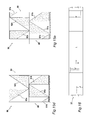
- FIG. 18 represents a partial scheme of an equipment for transversal perforations according to a third embodiment of the invention and comprising an eight variant of the component of FIG. 1 a;
- FIG. 19 is a partial lateral view of the equipment of FIG. 18 ;
- FIG. 20 is a partial front section of the equipment of FIG. 18 ;
- FIG. 21 shows a partial front section of the equipment of FIG. 18 with a ninth variant of the component of FIG. 1 a;
- FIG. 22 is the schematic view of a tenth variant of the component of FIG. 1 a;
- FIG. 23 shows a plan development of the component of FIG. 22 ;
- FIG. 24 is a schematic view of an eleventh variant of the component of FIG. 1 a ;
- FIG. 25 is a plan development of the component of FIG. 24 .
- FIG. 1 represents a perforating equipment 31 , according to the invention, for transversal perforations of variable lengths on continuous forms 32 ( FIG. 2 ) in movement.
- the equipment 31 ( FIG. 1 ) is also provided of one or more longitudinal perforating devices, not represented, for executing on the forms 32 longitudinal perforations in transversal positions and for longitudinal extensions settable by the user.
- These longitudinal perforating devices are of known type, and are herein not described as external to the present invention.
- the equipment 31 includes a perforating group 33 including a blade support 34 and a blade contrast 36 provided for rotation about respective parallel axes 37 and 38 transversally to a direction of movement “A” of the form 32 .
- the blade support 34 includes a bar with a section of elongated approximately rhomboidal shape, for a low rotational inertia, having an axis coincident with the axis 37 and including two active sectors of limited angular extension ( ⁇ 1, ⁇ 2) and on which are mounted two respective perforating blades 39 a and 39 b.
- the blade contrast 36 (See also FIG. 1 a ) is constituted by a cylinder of high hardness material with axis coincident with the axis 38 , including two projecting profiles 41 a and 41 b , of contrast for the blades 39 a and 39 b , and two depressed profiles 42 a and 42 b .
- the projecting profiles 41 a and 41 b define a cylindrical contrast surface, tangent to a movement surface of the continuous form 32 and axis coincident with the axis 37 , while the depressed profiles 42 a and 42 b are limited by surfaces depressed with respect to the movement surface of the form 32 .
- the equipment 31 also comprises a blade servomechanism 43 and a contrast servomechanism 44 for the support blade 34 and the blade contrast 36 and an electronic control unit 46 .
- the electronic unit 46 operates on the blade servomechanism 43 so as to position a selected perforating blade 39 a , 39 b in synchronism with a velocity Vm of the form 32 for executing transversal perforations in pre-defined areas of perforation “PA” of the form.
- the electronic unit 46 also operates on the contrast servomechanism 44 so as to precisely position a selected sector of the projecting profiles 41 a and 41 b in correspondence of the area “PA” provided for the perforation.
- the electronic control unit 46 operates on the blade servomechanism 43 to bring the support 34 from an inoperative condition of the blades to a condition of perforation in which a selected blade perforates the form for interference with the selected sector of one of the projecting profiles.
- the control unit 46 can also drive the blade servomechanism 43 so as to maintain the blade in movement, after the perforation, at a given basic velocity.
- the contrast servomechanism 44 positions the blade contrast 36 so as to have a sector of the depressed profiles 42 a or 42 b in front of the form 32 in movement, allowing the blade 39 a or 39 b to execute an idle run between two adjacent perforations.
- the perforating equipment 31 is structurally similar to the perforating equipment described in the Italian patent application TO 2010A000084, filed on 8 Feb. 2010 in the name of the applicant Tecnau S.r.l, and the content of which is herein included for reference.
- the blades 39 a and 39 b have a length “B1” congruent with perforations of maximum length “L” of the form 32 .
- the sectors constituting the projecting profiles 41 a and 41 b have different axial extensions “AE” increasing or decreasing in dependence of their angular position “ ⁇ ” with respect to a reference position “0”, while the contrast servomechanism 44 is settable for modifying the phases of the blade contrast 36 so as to selectively position, for the contrast with the perforating blade 39 a , 39 b on the areas “PA”, the sectors of the projecting profiles having axial extension equal to the desired lengths of the perforations.
- the positions and lengths of the perforations along the continuous form 32 are selectable according to the known technique, for example on the basis of coded information on the same form and/or specific controls of the user.
- the axial extensions “AE” of the sector constituting the projecting profiles 41 a and 41 b vary in a continuous manner in dependence of their angular position according to a given reference direction (clockwise in the figures), up to a maximum represented by a maximum length of perforation “L” of the continuous form 32 .
- FIG. 2 represents the plan development of the blade contrast 36 , in which the profiles 41 a and 41 b extend angularly for approximately 170° each with an axial extension of the sectors increasing in proportion to the angular position “ ⁇ ”: in the range from 0° to 170° for the projecting profile 41 a and from 180° to 350° for the projecting profile 41 b .
- the sectors between 170° and 180° and between 370° and 380° correspond in turn to the depressed profiles 42 a and 42 b , extended for the whole length of the blade contrast 36 .
- the positioning of the sectors with the depressed profiles in virtual positions of contrast causes a perforating blade 39 a , 39 b , in the passage on the flight, result inactive on the continuous form 32 .
- This configuration of projecting profiles and depressed profiles allows to execute on the form 32 ( FIG. 3 ) transversal perforations L1, L2, L3, of variable length, for angles ⁇ 1, ⁇ 2 and ⁇ 3 of the blade contrast 36 extending from a side conventionally right to a left side of the form 32 up to the maximum length “L”.
- the positioning in front of the area of perforation “PA” of the sector corresponding to the angle ⁇ 1, ⁇ 2, ⁇ 3 gives rise to the formation of an area of contrast limited to the length L1, L2, L3; the remaining surfaces are inherently spaced away from the movement surface, do not offer any resistance, and avoid perforations in excess of the length L1, L2, L3.
- the blade support 34 and the blade contrast 36 have their respective axes 37 and 38 inclined of a small angle “ ⁇ ” in a given direction with respect to a directrix perpendicular to the direction of movement “A” of the form 32 , while the perforating blades 39 a , 39 b have helical cutting edge with an angle equal to that of inclination of the axes.
- This angle “ ⁇ ” is between 0.2° and 3° and, preferably, in the range 0.5°-1.5°.
- the servocontrol systems provide high precision positioning and synchronization in the blade support and blade contrast.
- the continuous movement of the form 32 generates errors depending on deformations of the paper in the section between the transport motor members and the perforation assembly. This gives rise to longitudinal positioning errors, acceptable, of the order of 0.8 mm.
- the error in the length and positioning of the perforations is higher, but remains contained to about 1.5 mm, which represents a value acceptable by the market.
- FIG. 4 shows the plan development of a blade contrast 47 in accordance with the invention, which constitutes a first variant of the blade contrast 36 of FIG. 1 a .
- the blade contrast 47 includes two projecting profiles 48 a and 48 b , of contrast for the blades 39 a and 39 b and two depressed profiles 49 a and 49 b with angular distributions equal to those of the profiles 41 a and 41 b and the profiles 42 a or 42 b .
- the sizing is identical to that of the blade contrast 36 and also the axis of rotation 38 is inclined of the angle “ ⁇ ”.
- the axial extensions of the sectors regarding the projecting profiles 48 a and 48 b are decreasing with increasing angular position “ ⁇ ”.
- transversal perforations L4, L5, L6, of variable lengths which extend from the conventional left side to the-right side of the module.
- FIG. 6 a perforating equipment 51 , similar to the equipment 31 of FIG. 1 , in which components identical maintain the same numbering.
- the equipment 51 comprises, in addition to the perforating group 33 , a second perforating group, represented with 52 , with a blade support 53 , a blade contrast 54 , a blade servomechanism 56 and a respective contrast servomechanism 57 .
- the perforating groups 33 and 52 are arranged in cascade and in which the blade support 53 is identical to the blade support 34 , while the blade contrast 54 is identical to the blade contrast 47 .
- An electronic control unit 58 is settable to operate on the blade servomechanisms 43 and 56 and the contrast servomechanisms 36 and 57 of the perforating groups 33 and 53 to carry out both the variable perforations L1, L2, L3, starting from the left side of the continuous form 32 ( FIG. 7 ), and the variable perforations L4, L5, L6 starting from the right side, with no compromise in terms of operating speed and distance between the perforations.
- the axes of the blade support and the blade contrast, represented with 59 and 61 , and the perforating blades are also inclined of the angle “ ⁇ ” with respect to the directrix perpendicular to the direction of movement “A”, equal to or opposite to the angle of the axes 37 and 38 .
- FIG. 8 is shown a plain development of a second variant of the blade contrast in accordance with the invention, herein represented with 66 .
- the blade contrast 66 includes two projecting profiles 67 a and 67 b and two depressed profiles 68 a and 68 b having the same extensions of the projecting profiles 41 a and 41 b and the depressed profiles 42 a and 42 b and the same angular arrangements in the blade contrast 36 .
- the axial extensions of the projecting profile 67 a in the range from 0° to 170°, is increasing proportionally to the angular position “ ⁇ ” from the end conventionally right to the left end of the blade contrast 66 .
- the length of the profile 67 b is also increasing in the range 180° to 350° proportionally to the angular position “ ⁇ ”, but from the left to the right end of the blade contrast.
- the perforating equipment 31 of FIG. 1 can execute on the form 32 ( FIG. 7 ) both the transversal perforations of length L1, L2, L3, which extend from the side conventionally right to the left side of the form 32 and the perforations L4, L5, L6, which extend from the left to the right side.
- FIGS. 9 and 10 are shown the plan developments of a third and a fourth variant of the blade contrast in accordance with the invention, herein represented with 71 and 72 :
- the blade contrasts 71 and 72 are similar to the blade contrasts 36 and 47 , but include a single projecting profile 73 and, respectively, a single projecting profile 74 , of contrast for one or more perforating blades.
- the projecting profile 73 , 74 extends progressively up to a little less than 360°, and is adjacent to a respective depressed profile 76 , 77 .
- the axial extension of the projecting profile 73 is increasing while is decreasing the axial extension of the profile 74 .
- the error in the length of the perforations L1-L6 in the form 32 is acceptable and of the same order of magnitude (0.8 mm) of the error in the longitudinal positioning.
- the blade contrast 36 can provide sectors of contrast with axial extensions varying in a discreet way in dependence of predefined angular positions and having lengths and arrangements selected on the basis of requests of perforations selected by the users.
- the blade contrast 81 has a cross section of approximately elongated rectangular shape, similar to that of the support blade 36 , with two active cylindrical sectors 80 a and 80 b which insist on the section of shorter side.
- the sectors 80 a and 80 b have a diameter equal to that of the blade contrast 36 and limited angular extension “ ⁇ 1” and “ ⁇ 2”, for example 40°, for a low rotational inertia.
- the blade contrast 81 defines projecting profiles 82 a and 82 b in the active sectors 80 a and 80 b and depressed profiles 83 a and 83 b between the profiles 82 a and 82 b , extending for 140°, inactive for the contrast with the perforating blades.
- This structure ensures a limited inertia to the blade contrast 81 , similar to that of the support blade 36 , functional to a quick response of the control servomechanisms and a high perforation speed.
- each projecting profile 82 a and 82 b includes step sectors St 1 , St 2 , . . . , Stn.
- the axial extensions of the step sectors are variable in a discreet way in dependence of the their angular positions “ ⁇ ”, while are constant in the angular sector “ ⁇ ” of each step sector.
- the step sectors St 1 , St 2 , . . . , Stn of the projecting profiles 82 a and 82 b can be configurated so as to obtain the perforations starting from one side or the other of the form 32 , as represented in FIG. 11 , or be configurated to obtain perforations in intermediate areas between the sides of the form 32 .
- the axial extensions of the various sectors can be sized on the basis of lengths of perforations more used by the users as a de facto standard or on the basis of custom lengths and transversal positions established by the users.
- the blade contrast 81 can be mounted in replacing of the contrast member on a perforating equipment of the type described in the cited patent application TO 2010A000084. This allows also to this equipment a possibility of perforations of variable lengths on the basis of requests of perforations selected by the users, without replacing of mechanical components.
- the perforating blade may operate, without errors depending on angular deviations, on different areas of the step sectors that assure on the projecting profile of the same extension.
- the operating speed may be very high, with velocity Vm of the continuous form 32 of the order of 300 m/sec.
- the electronic control unit can be programmed for operating on the contrast servomechanism so as to vary progressively the phase of the blade contrast 81 in the range of equal axial extension. This is to arrange the areas of contrast in variable positions between the leading edges and the trailing edges of the angular sector or sectors of equal extension of the projecting profile 82 a or 82 b , in order to reduce the wear of the same projecting profiles 82 a and 82 b.
- the equipment of the invention uses a blade contrast 86 ( FIG. 13 ), with the plan development shown in FIG. 14 .
- the blade contrast 86 defines an axis 87 , analogous to the axis 37 of the blade contrast 36 , divided into two contiguous cylindrical trunks 88 and 89 , adjacent along the axis 87 .
- the trunks 88 and 89 include two respective projecting profiles 91 a and 91 b and 92 a and 92 b and depressed profiles 93 a and 93 b and 94 a and 94 b between the projecting profiles.
- Each trunk 88 and 89 is rotated about the axis 87 , with phases modifiable individually, by two respective contrast servomechanisms 96 and 97 .
- the maximum extension of the sectors of each of the profiles 91 a and 91 b and 92 a and 92 b is half the maximum length of perforation “L” of the continuous form 32 .
- the projecting profiles 91 a and 91 b of the first trunk 88 have sectors with axial extensions of increasing length in a range between 0° and 170° and, respectively, decreasing length between 180° and 350° from the end of reference of the contrast blade to the end adjacent to per second trunk 89 .
- the projecting profiles 92 a and 92 b of the trunk 89 have similar axial extensions, but of decreasing lengths and, respectively, increasing length from the end of the trunk adjacent to the first trunk to the opposite end of the blade contrast as shown in FIG. 14 .
- the servomechanisms 96 and 97 modify the respective phases of the trunk 88 and the trunk 89 so as to define a resultant sector, of contrast for the perforating blade, constituted by the sectors of a projecting profile of a single trunk 88 and 89 or by the sectors of the projecting profiles of both the trunks 88 and 89 with variable start and end, for perforations of variable lengths and start of the continuous form 32 .
- the two servomechanisms 96 and 97 are also coordinated so that, at the time of perforation, the overall behavior of the blade contrast 86 is equal to that of the blade contrast 36 of FIG. 1 .
- FIGS. 15 a -15 e are shown various configurations of the blade contrast 86 having different reciprocal phases of the trunks 88 and 89 .
- the continuous form 32 FIG. 16
- the perforating equipment 31 of the invention comprises the perforating group 33 with the blade support 34 and a blade contrast 101 ( FIG. 13 ), with low inertia, provided for rotating about the respective parallel axes 37 and 38 .
- the blade contrast 101 comprises a hollow cylinder 102 and a support shaft 103 with axes coinciding with the axis 37 and a series of ribs 104 integrally connected between the cylinder 102 and the shaft 103 .
- the hollow cylinder defines projecting profiles, of contrast for the blades 39 a and 39 b , and depressed profiles similar to the corresponding elements of the blade contrast 36 or the variants described above.
- the constituent parts of the blade contrast 101 are dimensioned so as to minimize the rotational inertia, without affecting the uniformity of perforation, along the entire width of the continuous form 32 .
- FIG. 18 a perforating equipment 111 , similar to the equipment 31 of FIG. 1 , in which components identical maintain the same numbering.
- the equipment 111 comprises the perforating group 33 with the blade support 34 and a blade contrast 112 ( FIGS. 18, 19 and 20 ), with low inertia, provided for rotating about the respective axes 37 and 38 .
- the blade contrast 112 represents an eight variant of the blade contrast 36 and comprises a hollow cylinder or sleeve 113 with projecting profiles, of contrast for the blades 39 a and 39 b , and depressed profiles similar to the corresponding elements of the blade contrast 36 or the blade contrasts 47 , 54 , 66 and 71 previously described.
- the hollow cylinder 113 is rotatable about a support shaft 114 , without mechanical contact, according to a structure constituting a radial air bearing of pneumostatic type.
- the shaft 114 is fixed between sides 116 and 117 of the equipment 111 through cylindrical tails 118 and 119 and respective fixing elements.
- the hollow cylinder 113 comprises terminal caps having hubs 121 and 122 and is suspended for pneumatic action, with an inner surface thereof on the shaft 114 and with the inner surfaces of the hubs 121 and 122 on the tails 118 and 119 .
- the components are of steel of high hardness and the internal surfaces of the hollow cylinder 113 and the hubs 121 and 122 are mirror finished and with tolerances such as to ensure that the gap of separation is of the order of 5-10 micron.
- the thickness of the hollow cylinder 113 is limited to a value sufficient to prevent irregularities in the perforations at the moment of impact of the blade with the projecting profile.
- the support shaft 114 is of high cross-section, such as to prevent corresponding flexural deformations.
- the hollow cylinder 113 has a thickness from 3.5 mm to 6 mm, typically 5 mm, while the support shaft has a diameter of 40-60 mm, typically 50 mm. With these values, the rotational inertia of the blade contrast 112 is similar to that of the blade support 34 .
- interposed washers 123 are interposed between the ends of the hubs 121 and 122 and the sides 116 and 117 , of calibrated thickness, so as to maintain the distance between the hubs and the sides within pre-defined limits, recovering machining and mounting tolerances in the distance between the sides 116 and 117 .
- the equipment 111 is connected to a compressed air source, not shown in the drawings, while the shaft 114 has an axial duct 124 and a series of radial ducts 126 of communication with the conduit 124 .
- a pipe 127 connects the duct 124 with the compressed air source, while the radial ducts 127 are open toward the space or gap of separation between the shaft 114 and the hollow cylinder 113 , for the generation of the pneumostatic action on the hollow cylinder.
- the compressed air is conveniently dehumidified and filtered and supplied to a pressure of 4-15 bar.
- the compressed air incoming from the pipe 127 flows through the axial duct 124 , the radial ducts 126 and the gap between cylinder 113 and shaft 114 and between hubs 122 and 123 and tails 118 and 119 , and escapes through the spaces between the washers 123 and the sides 116 and 117 .
- a contrast servomechanism 128 similar to the contrast servomechanism 44 includes a motor 129 which operates on the hollow cylinder 113 of the blade contrast 112 via a toothed crown 131 of the hub 121 and a pinion drive motor 132 and a toothed belt 133 .
- a structure of this type allows to have a blade contrast of very limited inertia, similar to that of the blade support 36 and subjected to minimum friction.
- the servomechanism 128 has therefore an extremely rapid response and can make use of components of limited power.
- the perforating equipment 111 uses a blade contrast 141 , ( FIG. 21 ), with pneumostatic suspension similar to that of the blade contrast 112 .
- the blade contrast 141 is formed by two contiguous trunks of cylinder 142 and 143 , adjacent along the axis 38 , which are rotatable, without mechanical contact, around the support shaft 114 .
- the trunk 142 is delimited by the terminal cap, with the hub 121 rotatable around the tail 118
- the trunk 143 is delimited by the cap with the hub 122 rotatable around the tail 119 .
- the trunks of cylinder 142 and 143 include two respective projecting profiles and depressed profiles between the identical projecting profiles to the projecting profiles 91 a and 91 b and 92 a and 92 b , and to the depressed profiles 93 a and 93 b and 94 a and 94 b of the blade contrast 86 of FIG. 13 .
- the trunks 142 and 143 are rotated around the support shaft 114 , as air bearings, with phases individually modifiable by two respective contrast servomechanisms 144 and 146 , similar to the contrast servomechanism 128 .
- Each servomechanism 144 , 146 includes a motor 147 which operates on the trunk 142 , 143 through a toothed crown 131 of the hub 121 , 122 and a transmission with a motor pinion 132 and a toothed belt 133 .
- the structure of the blade contrast 141 allows to have an inertia half that of the blade contrast 112 , which is also subject to minimum friction, particularly for small powers for the servomechanisms 144 , 146 and absolute freedom in the size and positioning of the perforations.
- the maximum extension of the sectors of each of the projecting profiles is equal to half the maximum length of perforation “L” of the continuous form 32 .
- the operation of the blade contrast 141 is identical to that of the blade contrast 86 .
- the increasing profile and the decreasing profile of the first trunk 142 have axial extensions of increasing lengths and, respectively, decreasing from an end of reference of the blade contrast 141 to one end of the trunk 142 contiguous with the second trunk 143 .
- the increasing profile and the decreasing profile of the second trunk have axial extensions of increasing length and, respectively, decreasing length from one end contiguous with the trunk 142 to one end of the blade contrast opposite to the end of reference.
- the respective angular positions of the trunk 142 and the trunk 143 are modifiable so as to define a resulting sector, of contrast for a perforating blade 39 a , 39 b , which is constituted by sectors of the projecting profiles of the two trunks, having variable start and end, for perforations of the continuous form ( 32 ) having freely selectionable lengths (L1, L2, . . . , L7) and transversal positions.
- the blade contrast 141 is similar to the blade contrast 112 .
- the air incoming from the pipe 127 flows through the axial duct 124 , the radial duct s 126 and the spaces between the trunks 142 and 143 and the shaft 114 and between the hubs 122 and 123 and the tails 118 and 119 and escapes through the spaces between the washers 123 and the sides 116 and 117 and through the space between the trunks 142 and 143 .
- the adjacent ends of the trunks 142 and 143 can be shaped as labyrinth, in order to minimize the escape of air between the trunks.
- the perforating equipment 111 with the blade contrast 141 or 142 allows to obtain very high perforation speed with feeding velocity Vm of the continuous form 32 of the order of 300 msec.
- FIGS. 22 and 24 and in FIGS. 23 and 25 are shown a tenth and an eleventh variant of the blade contrast, here represented with 151 and 152 and the respective plain developments.
- the blade contrasts 151 and 152 have two projecting profiles 153 a and 153 b and, respectively, a single projecting profile 154 and depressed profiles 156 a and 156 b and 157 . These profiles are similar to the projecting profiles 41 a and 41 b and 74 and the depressed profiles 42 a and 42 b and 76 of the blade contrast 36 of FIG. 1 a and the blade contrast 71 of FIG. 9 .
- the projecting profiles 153 a and 153 b and 154 have axial extension with continuous variation depending on their angular position but, on the contrary of the profiles 41 a and 41 b and 74 , the profiles 153 a and 153 b and 154 are interrupted in correspondence of two or more angular sectors with depressed profiles 178 and 179 .
- the depressed profiles 178 and 179 are such as to allow the inactive passage of the perforating blades, in the case of blades in continuous movement for high speed perforations.
- the projecting profiles 153 a and 153 b and 154 are configurated so as to have a same axial extension upstream and downstream of each interruption. This allows the user to ensure the maximum freedom in setting the length of perforation.
- the presence of the profiles 178 and 179 in turn allows to execute rotations of small value when the blade contrasts 151 and 152 must be rotated from the position regarding the last perforation to a position for the idle run of the blade.
- the projecting profiles 154 can be shaped so that, upstream and downstream of the depressed profiles 167 and 179 , are present small angular sectors 181 with identical axial extensions, as represented in FIG. 25 .
- the equipment of the invention with solid cylindrical contrast blades may provide a mechanism (not shown in the figures) for shifting the blade contrast with respect to the blade support, between a condition of perforation, of contrast for the blade, and an inoperative condition of disengagement for the blade.
- the blade servomechanism can maintain the blade in movement after the perforation and selectively execute an idle run of the blade between two adjacent perforations. In this case the projecting profiles will be absolutely continuous.
- a perforating equipment with a transversally shiftable blade contrast has been described in the Italian patent application TO 2009A000101, filed on 11 Feb. 2009 in the name of the applicant Tecnau S.r.l, and the content of which is herein included for reference.
- the contrast servomechanism and the electronic control unit can modify the phase of the blade contrast, to make operative for the contrast one of the projecting profiles having axial extension equal to the desired length of the perforations.
- the contrast servomechanism can directly actuate the rotation of the blade contrast, or to only modify the phase, by means of a differential mechanism, in the case where the blade contrast is rotated in synchronism with the form in movement.
- the equipment of the invention can also be used for executing of transversal cuts on the form, for example die cutting, with the simple substitution in the blade support of the perforating blade, typically indented, with a blade having a continuous cutting edge.
- the equipment for transverse perforations of the invention provides a contrast blade with one or more projecting profiles according to one of the above described solutions, having possibility of axial shifting and controlled by a further servomechanism.
- This servomechanism is settable to define a suitable axial position of the contrast blade such to define the start of the perforation on a whatsoever transversal position of the continuous form.
Applications Claiming Priority (4)
| Application Number | Priority Date | Filing Date | Title |
|---|---|---|---|
| ITTO2011A000445 | 2011-05-19 | ||
| IT000445A ITTO20110445A1 (it) | 2011-05-19 | 2011-05-19 | "equipaggiamento per perforazioni trasversali di lunghezze variabili, ad alta velocita, su moduli continui in movimento" |
| ITTO2011A0445 | 2011-05-19 | ||
| PCT/EP2012/059254 WO2012156506A1 (en) | 2011-05-19 | 2012-05-18 | Equipment for high speed transversal perforations of variable lengths on continuous forms in movement |
Publications (2)
| Publication Number | Publication Date |
|---|---|
| US20140174270A1 US20140174270A1 (en) | 2014-06-26 |
| US9592621B2 true US9592621B2 (en) | 2017-03-14 |
Family
ID=44554551
Family Applications (1)
| Application Number | Title | Priority Date | Filing Date |
|---|---|---|---|
| US14/235,525 Active 2032-12-02 US9592621B2 (en) | 2011-05-19 | 2012-05-18 | Equipment for high speed transversal perforations of variable lengths on continuous forms in movement |
Country Status (4)
| Country | Link |
|---|---|
| US (1) | US9592621B2 (it) |
| EP (1) | EP2709808B1 (it) |
| IT (2) | ITTO20110444A1 (it) |
| WO (1) | WO2012156506A1 (it) |
Cited By (8)
| Publication number | Priority date | Publication date | Assignee | Title |
|---|---|---|---|---|
| US11254024B2 (en) | 2013-06-12 | 2022-02-22 | The Procter & Gamble Company | Method of perforating a nonlinear line of weakness |
| US11268243B2 (en) | 2017-09-11 | 2022-03-08 | The Procter & Gamble Company | Sanitary tissue product with a shaped line of weakness |
| US11407608B2 (en) | 2015-03-17 | 2022-08-09 | The Procter & Gamble Company | Method for perforating a nonlinear line of weakness |
| US11413779B2 (en) | 2015-03-17 | 2022-08-16 | The Procter & Gamble Company | Apparatus for perforating a web material |
| US11584034B2 (en) | 2015-03-17 | 2023-02-21 | The Procter & Gamble Company | Apparatus for perforating a nonlinear line of weakness |
| US11745378B2 (en) | 2013-06-12 | 2023-09-05 | The Procter & Gamble Company | Nonlinear line of weakness formed by a perforating apparatus |
| US11806889B2 (en) | 2017-09-11 | 2023-11-07 | The Procter & Gamble Company | Perforating apparatus and method for manufacturing a shaped line of weakness |
| US11806890B2 (en) | 2017-09-11 | 2023-11-07 | The Procter & Gamble Company | Perforating apparatus and method for manufacturing a shaped line of weakness |
Families Citing this family (4)
| Publication number | Priority date | Publication date | Assignee | Title |
|---|---|---|---|---|
| US10744664B2 (en) | 2014-09-10 | 2020-08-18 | Fosber S.P.A. | Device for transverse cutting of a web material and machine containing said device |
| WO2016155752A1 (en) * | 2015-03-27 | 2016-10-06 | Hewlett-Packard Indigo B.V. | Rotary cutting device |
| WO2021253406A1 (zh) * | 2020-06-19 | 2021-12-23 | 超威电源集团有限公司 | 一种铅酸蓄电池极板的分片装置及方法 |
| DE102022207528A1 (de) * | 2022-07-22 | 2024-01-25 | Bhs Corrugated Maschinen- Und Anlagenbau Gmbh | Gegenzylinder-Anordnung |
Citations (34)
| Publication number | Priority date | Publication date | Assignee | Title |
|---|---|---|---|---|
| US3000250A (en) * | 1957-02-25 | 1961-09-19 | Eastman Kodak Co | Rotary cutter for producing a progressive transverse cut on a web |
| US3078796A (en) * | 1961-02-06 | 1963-02-26 | Kamata Hiroyuki | Vacuum clamping of plates for a rotary press |
| US3203292A (en) * | 1961-11-10 | 1965-08-31 | Schmermund Alfred | Cutting arrangements |
| US3230809A (en) * | 1963-11-13 | 1966-01-25 | Alfred A Luck | Cooperating rotary cutter blades with means to adjust angular traverse position of blades |
| US4020724A (en) * | 1975-02-06 | 1977-05-03 | Quinlan Albert J | Rotary cutting die |
| US4147312A (en) * | 1977-09-22 | 1979-04-03 | Great Lakes Industries, Inc. | Gas-liquid hydraulic expandable chucks and shafts |
| US4186633A (en) * | 1977-04-19 | 1980-02-05 | Apura Gmbh | Apparatus for dispensing sheets of web material of predetermined length |
| US4240312A (en) * | 1979-05-15 | 1980-12-23 | The Ward Machinery Company | Apparatus for improving wear life of rotary die cutter anvil covers |
| US4295843A (en) * | 1979-01-08 | 1981-10-20 | Mitsubishi Jukogyo Kabushiki Kaisha | Rotary die cutter |
| US4901627A (en) * | 1986-09-04 | 1990-02-20 | Eckehart Schulze | Hydraulic idling-regulating valve |
| US4939897A (en) * | 1988-07-29 | 1990-07-10 | Hollingsworth Gmbh | Opening cylinder unit for open-end spinning machines |
| DE4011365C1 (en) * | 1990-04-07 | 1991-04-25 | Eduard Kuesters Maschinenfabrik Gmbh & Co Kg, 4150 Krefeld, De | Control of bending of hollow roll - involves fixed shaft inside roll, with fluid film bearing pads engaging inside surface of roll |
| US5059286A (en) * | 1989-04-22 | 1991-10-22 | J.M. Voith Gmbh | Cylinder for the guiding of endless webs of material |
| US5170687A (en) * | 1991-01-25 | 1992-12-15 | Neumag-Neumunstersche Maschinen-Und Anlagenbau Gmbh | Machine for cutting staple fibers |
| US5257965A (en) * | 1989-05-12 | 1993-11-02 | Cerasiv Gmbh Innovatives Keramik-Engineering | Roller for pressure treatment of webs |
| US5284304A (en) * | 1991-04-03 | 1994-02-08 | Fabio Perini S.P.A. | Perforating apparatus for paper webs and the like, with reciprocating motion of translation of the counter-blade |
| US5388490A (en) * | 1990-05-10 | 1995-02-14 | Buck; Byron L. | Rotary die cutting system and method for sheet material |
| US5655444A (en) * | 1995-02-23 | 1997-08-12 | Voith Sulzer Finishing Gmbh | Calender for webs of paper |
| US5813959A (en) * | 1993-09-27 | 1998-09-29 | Eduard Kusters Maschinenfabrik Gmbh & Co. Kg | Roller |
| US5967957A (en) * | 1995-07-26 | 1999-10-19 | Eduard Kusters Maschinenfabrik Gmbh & Co. | Roller assembly with internal supporting elements |
| US6045492A (en) * | 1996-07-25 | 2000-04-04 | Eduard Kusters Maschinenfabrik GmbH & Co K.G. | Web pressing roller |
| US6135002A (en) * | 1998-04-27 | 2000-10-24 | Neal; Kenneth Ray | Die cutter blanket and bearing and method of arranging the blanket and bearing on an anvil |
| US6494398B1 (en) * | 1998-12-31 | 2002-12-17 | M T C Macchine Trasformazione Carta S.R.L., | Rewinding method and machine for making logs of paper and the like |
| US6659926B2 (en) * | 2001-07-25 | 2003-12-09 | Voith Paper Patent Gmbh | Deflection controlled roll |
| US6889587B2 (en) * | 2003-06-04 | 2005-05-10 | Robud | Die cutter blanket |
| US7146893B2 (en) * | 2001-02-21 | 2006-12-12 | Aichele Werkzeuge Gmbh | Cutting device and cutting tool |
| US7430948B2 (en) * | 2003-05-20 | 2008-10-07 | Tecnau S.R.L. | Cutting equipment for continuous form |
| US7484445B2 (en) * | 2003-06-04 | 2009-02-03 | Tecnau S.R.L. | Punching and/or perforating equipment for continuous forms |
| US20090071608A1 (en) * | 2007-09-03 | 2009-03-19 | Krones Ag | All-round labelling apparatus |
| US7784386B2 (en) * | 2007-06-29 | 2010-08-31 | Lee Tack Plastic & Metal Manufactory Ltd | Paper cutting apparatus |
| US20110192263A1 (en) * | 2010-02-08 | 2011-08-11 | Tecnau S.R.L. | Equipment For Transversal Perforation, On The Fly, Of Continuous Forms In Movement |
| US8336435B2 (en) * | 2004-11-03 | 2012-12-25 | Sandvik Intellectual Property Ab | Anvil for a rotary cutting unit and a rotary cutting unit having an anvil |
| US8353236B2 (en) * | 2009-02-11 | 2013-01-15 | TECNAU, S.r.l. | Perforating equipment for continuous forms in movement |
| US8783144B2 (en) * | 2009-05-13 | 2014-07-22 | Bobst Mex Sa | Waste stripping unit with simplified tool change for a packaging production machine |
Family Cites Families (3)
| Publication number | Priority date | Publication date | Assignee | Title |
|---|---|---|---|---|
| AU1189797A (en) * | 1995-12-22 | 1997-07-17 | Wjc Systec A/S | Method and device for perforating and/or cutting and/or scoring a web. |
| GB0122795D0 (en) * | 2001-09-21 | 2001-11-14 | Shape Technology Ltd | Roller bearing assembly |
| DE10356037A1 (de) * | 2003-12-01 | 2005-07-07 | Bhs Corrugated Maschinen- Und Anlagenbau Gmbh | Schneid-Vorrichtung |
-
2011
- 2011-05-19 IT IT000444A patent/ITTO20110444A1/it unknown
- 2011-05-19 IT IT000445A patent/ITTO20110445A1/it unknown
-
2012
- 2012-05-18 EP EP12726757.3A patent/EP2709808B1/en active Active
- 2012-05-18 WO PCT/EP2012/059254 patent/WO2012156506A1/en active Application Filing
- 2012-05-18 US US14/235,525 patent/US9592621B2/en active Active
Patent Citations (34)
| Publication number | Priority date | Publication date | Assignee | Title |
|---|---|---|---|---|
| US3000250A (en) * | 1957-02-25 | 1961-09-19 | Eastman Kodak Co | Rotary cutter for producing a progressive transverse cut on a web |
| US3078796A (en) * | 1961-02-06 | 1963-02-26 | Kamata Hiroyuki | Vacuum clamping of plates for a rotary press |
| US3203292A (en) * | 1961-11-10 | 1965-08-31 | Schmermund Alfred | Cutting arrangements |
| US3230809A (en) * | 1963-11-13 | 1966-01-25 | Alfred A Luck | Cooperating rotary cutter blades with means to adjust angular traverse position of blades |
| US4020724A (en) * | 1975-02-06 | 1977-05-03 | Quinlan Albert J | Rotary cutting die |
| US4186633A (en) * | 1977-04-19 | 1980-02-05 | Apura Gmbh | Apparatus for dispensing sheets of web material of predetermined length |
| US4147312A (en) * | 1977-09-22 | 1979-04-03 | Great Lakes Industries, Inc. | Gas-liquid hydraulic expandable chucks and shafts |
| US4295843A (en) * | 1979-01-08 | 1981-10-20 | Mitsubishi Jukogyo Kabushiki Kaisha | Rotary die cutter |
| US4240312A (en) * | 1979-05-15 | 1980-12-23 | The Ward Machinery Company | Apparatus for improving wear life of rotary die cutter anvil covers |
| US4901627A (en) * | 1986-09-04 | 1990-02-20 | Eckehart Schulze | Hydraulic idling-regulating valve |
| US4939897A (en) * | 1988-07-29 | 1990-07-10 | Hollingsworth Gmbh | Opening cylinder unit for open-end spinning machines |
| US5059286A (en) * | 1989-04-22 | 1991-10-22 | J.M. Voith Gmbh | Cylinder for the guiding of endless webs of material |
| US5257965A (en) * | 1989-05-12 | 1993-11-02 | Cerasiv Gmbh Innovatives Keramik-Engineering | Roller for pressure treatment of webs |
| DE4011365C1 (en) * | 1990-04-07 | 1991-04-25 | Eduard Kuesters Maschinenfabrik Gmbh & Co Kg, 4150 Krefeld, De | Control of bending of hollow roll - involves fixed shaft inside roll, with fluid film bearing pads engaging inside surface of roll |
| US5388490A (en) * | 1990-05-10 | 1995-02-14 | Buck; Byron L. | Rotary die cutting system and method for sheet material |
| US5170687A (en) * | 1991-01-25 | 1992-12-15 | Neumag-Neumunstersche Maschinen-Und Anlagenbau Gmbh | Machine for cutting staple fibers |
| US5284304A (en) * | 1991-04-03 | 1994-02-08 | Fabio Perini S.P.A. | Perforating apparatus for paper webs and the like, with reciprocating motion of translation of the counter-blade |
| US5813959A (en) * | 1993-09-27 | 1998-09-29 | Eduard Kusters Maschinenfabrik Gmbh & Co. Kg | Roller |
| US5655444A (en) * | 1995-02-23 | 1997-08-12 | Voith Sulzer Finishing Gmbh | Calender for webs of paper |
| US5967957A (en) * | 1995-07-26 | 1999-10-19 | Eduard Kusters Maschinenfabrik Gmbh & Co. | Roller assembly with internal supporting elements |
| US6045492A (en) * | 1996-07-25 | 2000-04-04 | Eduard Kusters Maschinenfabrik GmbH & Co K.G. | Web pressing roller |
| US6135002A (en) * | 1998-04-27 | 2000-10-24 | Neal; Kenneth Ray | Die cutter blanket and bearing and method of arranging the blanket and bearing on an anvil |
| US6494398B1 (en) * | 1998-12-31 | 2002-12-17 | M T C Macchine Trasformazione Carta S.R.L., | Rewinding method and machine for making logs of paper and the like |
| US7146893B2 (en) * | 2001-02-21 | 2006-12-12 | Aichele Werkzeuge Gmbh | Cutting device and cutting tool |
| US6659926B2 (en) * | 2001-07-25 | 2003-12-09 | Voith Paper Patent Gmbh | Deflection controlled roll |
| US7430948B2 (en) * | 2003-05-20 | 2008-10-07 | Tecnau S.R.L. | Cutting equipment for continuous form |
| US6889587B2 (en) * | 2003-06-04 | 2005-05-10 | Robud | Die cutter blanket |
| US7484445B2 (en) * | 2003-06-04 | 2009-02-03 | Tecnau S.R.L. | Punching and/or perforating equipment for continuous forms |
| US8336435B2 (en) * | 2004-11-03 | 2012-12-25 | Sandvik Intellectual Property Ab | Anvil for a rotary cutting unit and a rotary cutting unit having an anvil |
| US7784386B2 (en) * | 2007-06-29 | 2010-08-31 | Lee Tack Plastic & Metal Manufactory Ltd | Paper cutting apparatus |
| US20090071608A1 (en) * | 2007-09-03 | 2009-03-19 | Krones Ag | All-round labelling apparatus |
| US8353236B2 (en) * | 2009-02-11 | 2013-01-15 | TECNAU, S.r.l. | Perforating equipment for continuous forms in movement |
| US8783144B2 (en) * | 2009-05-13 | 2014-07-22 | Bobst Mex Sa | Waste stripping unit with simplified tool change for a packaging production machine |
| US20110192263A1 (en) * | 2010-02-08 | 2011-08-11 | Tecnau S.R.L. | Equipment For Transversal Perforation, On The Fly, Of Continuous Forms In Movement |
Cited By (12)
| Publication number | Priority date | Publication date | Assignee | Title |
|---|---|---|---|---|
| US11254024B2 (en) | 2013-06-12 | 2022-02-22 | The Procter & Gamble Company | Method of perforating a nonlinear line of weakness |
| US11697219B2 (en) | 2013-06-12 | 2023-07-11 | The Procter & Gamble Company | Method of perforating a nonlinear line of weakness |
| US11745378B2 (en) | 2013-06-12 | 2023-09-05 | The Procter & Gamble Company | Nonlinear line of weakness formed by a perforating apparatus |
| US11407608B2 (en) | 2015-03-17 | 2022-08-09 | The Procter & Gamble Company | Method for perforating a nonlinear line of weakness |
| US11413779B2 (en) | 2015-03-17 | 2022-08-16 | The Procter & Gamble Company | Apparatus for perforating a web material |
| US11584034B2 (en) | 2015-03-17 | 2023-02-21 | The Procter & Gamble Company | Apparatus for perforating a nonlinear line of weakness |
| US11661301B2 (en) | 2015-03-17 | 2023-05-30 | The Procter & Gamble Company | Method for perforating a nonlinear line of weakness |
| US11268243B2 (en) | 2017-09-11 | 2022-03-08 | The Procter & Gamble Company | Sanitary tissue product with a shaped line of weakness |
| US11668051B2 (en) | 2017-09-11 | 2023-06-06 | The Procter & Gamble Company | Sanitary tissue product with a shaped line of weakness |
| US11806889B2 (en) | 2017-09-11 | 2023-11-07 | The Procter & Gamble Company | Perforating apparatus and method for manufacturing a shaped line of weakness |
| US11806890B2 (en) | 2017-09-11 | 2023-11-07 | The Procter & Gamble Company | Perforating apparatus and method for manufacturing a shaped line of weakness |
| US11952722B2 (en) | 2017-09-11 | 2024-04-09 | The Procter & Gamble Company | Sanitary tissue product with a shaped line of weakness |
Also Published As
| Publication number | Publication date |
|---|---|
| ITTO20110444A1 (it) | 2012-11-20 |
| US20140174270A1 (en) | 2014-06-26 |
| ITTO20110445A1 (it) | 2012-11-20 |
| EP2709808B1 (en) | 2016-04-20 |
| WO2012156506A1 (en) | 2012-11-22 |
| EP2709808A1 (en) | 2014-03-26 |
Similar Documents
| Publication | Publication Date | Title |
|---|---|---|
| US9592621B2 (en) | Equipment for high speed transversal perforations of variable lengths on continuous forms in movement | |
| US8353236B2 (en) | Perforating equipment for continuous forms in movement | |
| US20110192263A1 (en) | Equipment For Transversal Perforation, On The Fly, Of Continuous Forms In Movement | |
| US5797305A (en) | On demand cross web perforation | |
| US10744664B2 (en) | Device for transverse cutting of a web material and machine containing said device | |
| CN107599033B (zh) | 用于切割烟草加工业的材料幅材条带的装置和方法 | |
| CN108178007B (zh) | 用于卷绕薄带的收放传动机构 | |
| CN102548879A (zh) | 波纹边缘轧辊 | |
| US20100101386A1 (en) | Variable signature length web cutting apparatus | |
| TWI605893B (zh) | 用於分條機之輕化型刀套 | |
| JP2017527736A (ja) | ブレードの向きを調節するための部材を駆動するための機構 | |
| US20020088322A1 (en) | Cutting unit incorporating a helical mechanism for varying a cutting length and method for operating the cutting unit | |
| JP6400404B2 (ja) | 巻き線装置、巻き線方法 | |
| EP3198152A1 (de) | Axiallüfter zur förderung von kühlluft, insbesondere für einen verbrennungsmotor eines kraftfahrzeuges | |
| GB2322822A (en) | Longitudinal web slitting device | |
| CN211466531U (zh) | 一种复合彩膜分切装置 | |
| EP2593359B1 (en) | Feathering propeller with blade dampening at forward and backward motion and blades pitch control during backward motion | |
| JP2012144304A (ja) | 裁ち屑巻取装置 | |
| RU2020115567A (ru) | Лопасть несущего или гребного винта с динамической оптимизацией формы и других параметров в пределах одного оборота | |
| US1826601A (en) | Sheet cutting, collecting, and folding mechanism | |
| CN203233921U (zh) | 钓线卷绕用卷筒以及搭载有该卷筒的钓鱼用卷线器 | |
| EP1790444A2 (de) | Messerzylinder zum Trennen von Bahnmaterial | |
| JP2023028735A (ja) | スリッターおよびスリッターにおけるカッターの配置変更方法 | |
| JP2013033093A (ja) | 吊線付き光ファイバケーブル製造装置 | |
| JP2005074994A (ja) | 薄皮ペーパー加工装置及び薄皮ペーパー |
Legal Events
| Date | Code | Title | Description |
|---|---|---|---|
| AS | Assignment |
Owner name: TECNAU S.R.L., ITALY Free format text: ASSIGNMENT OF ASSIGNORS INTEREST;ASSIGNORS:DEMARCO, GIULIANO;APRATO, ARMANDO;TERRUSI, FRANCESCO;AND OTHERS;REEL/FRAME:032061/0089 Effective date: 20131227 |
|
| STCF | Information on status: patent grant |
Free format text: PATENTED CASE |
|
| MAFP | Maintenance fee payment |
Free format text: PAYMENT OF MAINTENANCE FEE, 4TH YR, SMALL ENTITY (ORIGINAL EVENT CODE: M2551); ENTITY STATUS OF PATENT OWNER: SMALL ENTITY Year of fee payment: 4 |