US9534318B2 - Vitreous silica crucible and method of manufacturing the same - Google Patents
Vitreous silica crucible and method of manufacturing the same Download PDFInfo
- Publication number
- US9534318B2 US9534318B2 US13/335,885 US201113335885A US9534318B2 US 9534318 B2 US9534318 B2 US 9534318B2 US 201113335885 A US201113335885 A US 201113335885A US 9534318 B2 US9534318 B2 US 9534318B2
- Authority
- US
- United States
- Prior art keywords
- groove line
- vitreous silica
- crucible
- width
- silica powder
- Prior art date
- Legal status (The legal status is an assumption and is not a legal conclusion. Google has not performed a legal analysis and makes no representation as to the accuracy of the status listed.)
- Active, expires
Links
Images


Classifications
-
- C—CHEMISTRY; METALLURGY
- C03—GLASS; MINERAL OR SLAG WOOL
- C03C—CHEMICAL COMPOSITION OF GLASSES, GLAZES OR VITREOUS ENAMELS; SURFACE TREATMENT OF GLASS; SURFACE TREATMENT OF FIBRES OR FILAMENTS MADE FROM GLASS, MINERALS OR SLAGS; JOINING GLASS TO GLASS OR OTHER MATERIALS
- C03C23/00—Other surface treatment of glass not in the form of fibres or filaments
- C03C23/0005—Other surface treatment of glass not in the form of fibres or filaments by irradiation
- C03C23/0025—Other surface treatment of glass not in the form of fibres or filaments by irradiation by a laser beam
-
- C—CHEMISTRY; METALLURGY
- C03—GLASS; MINERAL OR SLAG WOOL
- C03B—MANUFACTURE, SHAPING, OR SUPPLEMENTARY PROCESSES
- C03B20/00—Processes specially adapted for the production of quartz or fused silica articles, not otherwise provided for
-
- C—CHEMISTRY; METALLURGY
- C30—CRYSTAL GROWTH
- C30B—SINGLE-CRYSTAL GROWTH; UNIDIRECTIONAL SOLIDIFICATION OF EUTECTIC MATERIAL OR UNIDIRECTIONAL DEMIXING OF EUTECTOID MATERIAL; REFINING BY ZONE-MELTING OF MATERIAL; PRODUCTION OF A HOMOGENEOUS POLYCRYSTALLINE MATERIAL WITH DEFINED STRUCTURE; SINGLE CRYSTALS OR HOMOGENEOUS POLYCRYSTALLINE MATERIAL WITH DEFINED STRUCTURE; AFTER-TREATMENT OF SINGLE CRYSTALS OR A HOMOGENEOUS POLYCRYSTALLINE MATERIAL WITH DEFINED STRUCTURE; APPARATUS THEREFOR
- C30B35/00—Apparatus not otherwise provided for, specially adapted for the growth, production or after-treatment of single crystals or of a homogeneous polycrystalline material with defined structure
- C30B35/002—Crucibles or containers
-
- C—CHEMISTRY; METALLURGY
- C03—GLASS; MINERAL OR SLAG WOOL
- C03B—MANUFACTURE, SHAPING, OR SUPPLEMENTARY PROCESSES
- C03B19/00—Other methods of shaping glass
- C03B19/09—Other methods of shaping glass by fusing powdered glass in a shaping mould
- C03B19/095—Other methods of shaping glass by fusing powdered glass in a shaping mould by centrifuging, e.g. arc discharge in rotating mould
-
- C—CHEMISTRY; METALLURGY
- C30—CRYSTAL GROWTH
- C30B—SINGLE-CRYSTAL GROWTH; UNIDIRECTIONAL SOLIDIFICATION OF EUTECTIC MATERIAL OR UNIDIRECTIONAL DEMIXING OF EUTECTOID MATERIAL; REFINING BY ZONE-MELTING OF MATERIAL; PRODUCTION OF A HOMOGENEOUS POLYCRYSTALLINE MATERIAL WITH DEFINED STRUCTURE; SINGLE CRYSTALS OR HOMOGENEOUS POLYCRYSTALLINE MATERIAL WITH DEFINED STRUCTURE; AFTER-TREATMENT OF SINGLE CRYSTALS OR A HOMOGENEOUS POLYCRYSTALLINE MATERIAL WITH DEFINED STRUCTURE; APPARATUS THEREFOR
- C30B15/00—Single-crystal growth by pulling from a melt, e.g. Czochralski method
- C30B15/10—Crucibles or containers for supporting the melt
-
- C—CHEMISTRY; METALLURGY
- C30—CRYSTAL GROWTH
- C30B—SINGLE-CRYSTAL GROWTH; UNIDIRECTIONAL SOLIDIFICATION OF EUTECTIC MATERIAL OR UNIDIRECTIONAL DEMIXING OF EUTECTOID MATERIAL; REFINING BY ZONE-MELTING OF MATERIAL; PRODUCTION OF A HOMOGENEOUS POLYCRYSTALLINE MATERIAL WITH DEFINED STRUCTURE; SINGLE CRYSTALS OR HOMOGENEOUS POLYCRYSTALLINE MATERIAL WITH DEFINED STRUCTURE; AFTER-TREATMENT OF SINGLE CRYSTALS OR A HOMOGENEOUS POLYCRYSTALLINE MATERIAL WITH DEFINED STRUCTURE; APPARATUS THEREFOR
- C30B29/00—Single crystals or homogeneous polycrystalline material with defined structure characterised by the material or by their shape
- C30B29/02—Elements
- C30B29/06—Silicon
-
- B—PERFORMING OPERATIONS; TRANSPORTING
- B41—PRINTING; LINING MACHINES; TYPEWRITERS; STAMPS
- B41M—PRINTING, DUPLICATING, MARKING, OR COPYING PROCESSES; COLOUR PRINTING
- B41M5/00—Duplicating or marking methods; Sheet materials for use therein
- B41M5/26—Thermography ; Marking by high energetic means, e.g. laser otherwise than by burning, and characterised by the material used
- B41M5/262—Thermography ; Marking by high energetic means, e.g. laser otherwise than by burning, and characterised by the material used recording or marking of inorganic surfaces or materials, e.g. glass, metal, or ceramics
-
- C—CHEMISTRY; METALLURGY
- C30—CRYSTAL GROWTH
- C30B—SINGLE-CRYSTAL GROWTH; UNIDIRECTIONAL SOLIDIFICATION OF EUTECTIC MATERIAL OR UNIDIRECTIONAL DEMIXING OF EUTECTOID MATERIAL; REFINING BY ZONE-MELTING OF MATERIAL; PRODUCTION OF A HOMOGENEOUS POLYCRYSTALLINE MATERIAL WITH DEFINED STRUCTURE; SINGLE CRYSTALS OR HOMOGENEOUS POLYCRYSTALLINE MATERIAL WITH DEFINED STRUCTURE; AFTER-TREATMENT OF SINGLE CRYSTALS OR A HOMOGENEOUS POLYCRYSTALLINE MATERIAL WITH DEFINED STRUCTURE; APPARATUS THEREFOR
- C30B15/00—Single-crystal growth by pulling from a melt, e.g. Czochralski method
-
- Y—GENERAL TAGGING OF NEW TECHNOLOGICAL DEVELOPMENTS; GENERAL TAGGING OF CROSS-SECTIONAL TECHNOLOGIES SPANNING OVER SEVERAL SECTIONS OF THE IPC; TECHNICAL SUBJECTS COVERED BY FORMER USPC CROSS-REFERENCE ART COLLECTIONS [XRACs] AND DIGESTS
- Y10—TECHNICAL SUBJECTS COVERED BY FORMER USPC
- Y10T—TECHNICAL SUBJECTS COVERED BY FORMER US CLASSIFICATION
- Y10T117/00—Single-crystal, oriented-crystal, and epitaxy growth processes; non-coating apparatus therefor
- Y10T117/10—Apparatus
Definitions
- the present invention relates to a vitreous silica crucible and a method of manufacturing the same.
- silicon single crystal is manufactured by melting high-purity polycrystalline silicon in a vitreous silica crucible to obtain silicon melt, dipping an end of a seed crystal to the silicon melt, and pulling the seed crystal while rotating it.
- silica powder is deposited on an inner surface of a rotating mold, and arc fusing process is carried out to fuse the silica powder.
- a honing process is carried out to remove unfused silica powder attached on an outer surface of the crucible by spraying high-pressure water onto the outer surface of the crucible.
- a rim cutting process is carried out to cut, in a certain width, an opening edge of the crucible so that the height after the rim cutting process is set to a predetermined value.
- washing process, drying process, inspection process, and HF (hydrofluoric acid) washing process are carried out before the vitreous silica crucible is shipped.
- JP-U-2533643 discloses a method of grinding an identifying mark, indicating the grade of the crucible, on the outer surface of the crucible by use of a diamond air tool or the like.
- the grade of a crucible is identified by the number of recesses formed on the outer surface of the crucible. According to this method, a small number of crucibles can be distinguished. However, as the number of the kinds of crucibles increases, the number of recesses increases. Therefore, in view of manufacturing efficiency, it is not feasible to employ the technique of JP-U-2533643 in order to identify crucibles having various specifications.
- JP-A-H11-209136 discloses a method of carrying out marking on a vitreous silica member by use of a YAG laser marker.
- the marking by use of a laser marker is relatively high speed, and it is possible to mark various symbols such as bar code, character, mark, sign, numeric character or the like. Therefore, the method of JP-A-H11-209136 is suitable for identification of various kinds of crucibles having different specifications.
- the marking is formed by the processes of contacting a plate made of carbon or the like on a predetermined portion of a vitreous silica member, and irradiating the portion with a YAG laser through the vitreous silica member to print the carbon or the like on the vitreous silica member.
- the carbon or the like can be detached during pulling a silicon ingot, and can be mixed in silicon melt.
- any of the prior art is not useful for identification of various kinds of crucibles having different specifications, and thus the operators make a lot of effort to prevent mix-up of the crucibles in the manufacturing process.
- the present invention has been made in view of these circumstances, and provides a method of manufacturing a vitreous silica crucible so that mix-up of crucibles in the manufacturing process can be prevented.
- a method of manufacturing a vitreous silica crucible comprising: a silica powder layer forming process of forming a silica powder layer by depositing silica powder on an inner surface of a mold defining an outer shape of a vitreous silica crucible; an arc heating process of fusing, by arc heating, the silica powder layer in the mold to form a vitreous silica crucible having a vitreous silica layer and terminating the arc heating so as to leave unfused silica powder layer between the vitreous silica layer and the mold; a taking-out process of taking out the vitreous silica crucible from the mold; a honing process of removing the unfused silica powder layer on the outer surface of the vitreous silica crucible, and further comprising, after the taking-out process and before the honing process, a marking process of marking an identifier comprised of one or more groove line on the
- the present inventors have made extensive research on how to prevent mix-up of crucibles in the manufacturing process, and come up with an idea of marking an identifier after the taking-out process and before the honing process.
- unfused silica powder is attached to an outer surface of a vitreous silica crucible just after the taking-out process, and thus it is an general conception that it is inappropriate to carry out marking just after the taking-out process, and it is common sense to mark an identifier after removing the unfused silica powder in the honing process.
- the present inventors despite of the common sense, have come up with an idea of marking the identifier in a state the unfused silica powder is attached to the outer surface of the vitreous silica crucible before the honing process.
- a vitreous silica crucible is subjected to one or more process without an identifier between the arc heating process and the marking process, and thus mix-up of crucibles is likely to occur.
- the marking is carried out after the taking-out process and before the honing process, the marking is provided before the crucible is moved to a different place after the crucible is taken out of the mold. Therefore, mix-up of crucibles is unlikely to occur.
- the present inventors have come up with an idea of marking an identifier comprised of one or more groove line.
- the “identifier” refers to a symbol which can be used for identification of the kind of a crucible, and is comprised of, for example, character, numeric character, or bar code.
- the present invention use an identifier comprised of one or more groove line, and thus can produce various kinds of identifiers, and thus can recognize various kinds of crucibles easily.
- the line of the identifier has a depth of 0.2 to 0.5 mm after the honing process, and a width of 0.8 mm or more at the opening of the groove line. It is also an important point of the present invention to have the identifier with such depth and width.
- the unfused silica powder layer is removed and water gets into the groove line, and thus the visual recognition of the groove line becomes difficult.
- the depth after the honing process is less than 0.2 mm or the width after the honing process is less than 0.8 mm
- the visual recognition of the groove line is difficult and thus the visual recognition of the identifier is difficult.
- the visual recognition of the groove line becomes easier.
- the groove line has a depth of more than 0.5 mm, cracks are more likely to be formed in the crucible.
- the mix-up of crucibles during manufacturing process can be prevented.
- FIG. 1 is a flowchart showing a manufacturing process of a vitreous silica crucible according to one embodiment of the present invention.
- FIG. 2 is a sectional view for explaining a silica powder layer forming process according to one embodiment of the present invention.
- FIG. 3 is a sectional view for explaining an arc heating process according to one embodiment of the present invention.
- FIG. 4 is a sectional view for explaining a taking-out process according to one embodiment of the present invention.
- FIG. 5 is a view showing a configuration of an identifier according to one embodiment of the present invention.
- FIGS. 6( a ) and 6( b ) are sectional views showing a configuration of a groove line according to one embodiment of the present invention, and FIG. 6( a ) shows a state before the honing process, and FIG. 6( b ) shows a state after the honing process.
- FIGS. 7( a ) and 7( b ) are sectional views showing another configuration of a groove line according to one embodiment of the present invention, and FIG. 7( a ) shows a state before the honing process, and FIG. 7( b ) shows a state after the honing process.
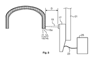
- FIG. 8 is a view showing a method of marking an identifier by use of a laser marker according to one embodiment of the present invention.
- FIGS. 9( a ) and 9( b ) are sectional views showing a method of carrying out laser scanning at plural positions in the width direction.
- the method of a vitreous silica crucible of the present embodiment includes a silica powder layer forming process of forming a silica powder layer 3 by depositing silica powder on an inner surface of a mold 1 defining an outer shape of a vitreous silica crucible 14 , an arc heating process of fusing, by arc heating, the silica powder layer 3 in the mold 1 to form a vitreous silica crucible 14 having a vitreous silica layer 13 and terminating the arc heating so as to leave unfused silica powder layer 15 between the vitreous silica layer 13 and the mold 1 , a taking-out process of taking out the vitreous silica crucible 14 from the mold 1 , a honing process of removing the unfused silica powder layer 15 a on the outer surface of the vitreous silica crucible 14 , and further comprising, after the taking-out process and before the honing process, a marking process of marking an
- the method optionally further includes, after the honing process, a rim-cut process of removing, in a certain width, an opening edge of the vitreous silica crucible 14 , a washing and drying process of washing and drying the vitreous silica crucible 14 , and an inspection process of inspecting the vitreous silica crucible 14 .
- the method optionally further includes a grinding process of removing the foreign substance by grinding, and re-arc heating process of arc heating the vitreous silica crucible 14 after the grinding.
- Step S 1 Silica Powder Layer Forming Process
- silica powder is deposited on an inner surface of a mold 1 defining an outer shape of a vitreous silica crucible to form a silica powder layer 3 .
- the mold 1 is rotatable around an axis 7 , and silica powder is supplied to the mold 1 while rotating the mold 1 .
- the mold 1 contains many ventilation holes 5 , and the silica powder layer 3 is depressurized via the ventilation holes 5 during the fusing the silica powder layer 3 by arc heating.
- the vitreous silica crucible has a shape of, for example, a corner portion having a relatively large curvature, and a cylindrical sidewall portion having an upward opening, and a bottom portion which is flat or has a relatively small curvature.
- the corner portion refers to a portion connecting the sidewall portion and the bottom portion, and starts at a point where a line tangential to the corner portion overlaps with the sidewall portion and ends at a point where the corner portion and the bottom portion have a common tangential line.
- the boundary between the sidewall portion and the corner portion is a point where a straight portion of a wall of the crucible starts to curve.
- the portion with a constant curvature at the bottom of the crucible is the bottom portion, and as the distance from the center of the crucible increases, a point where the curvature starts to change is the boundary between the bottom portion and the corner portion.
- Silica powder may be either natural silica powder or synthetic silica powder. Natural silica powder can be manufactured by pulverizing natural mineral whose main component is ⁇ -quartz. Synthetic silica powder can be manufactured by chemical synthesis, such as gas phase oxidation (dry synthesis) of silicon tetrachloride (SiCl 4 ), or hydrolysis (sol-gel method) of silicon alkoxide (Si(OR) 4 ).
- the silica powder layer 3 can be formed, in one example, by depositing natural silica powder and thereafter depositing synthetic silica powder.
- Natural vitreous silica made of natural silica powder has relatively large viscosity, and synthetic vitreous silica made of synthetic silica powder is highly-pure. Therefore, it is possible to form the silica powder layer 3 comprised of a natural silica powder layer on the outer side and a synthetic silica powder layer on the inner side, to manufacture a crucible having an inner surface with high purity and having a large strength.
- the average particle diameter of silica powder is, for example, 200 to 600 ⁇ m. When the average diameter is too small, the silica powder readily hovers during forming a silica powder layer or arc fusing the silica powder layer. When the average diameter is too large, the surface of the silica powder layer is more likely to be rough.
- particle size is, in general, as shown in the section of the term definition of “Test Powder and Test Particles” in JIS Z 8901, a size represented by the aperture size of a test sieve used for the measurement in the screening method, a size represented by the Stokes equivalent diameter obtained by the sedimentation method, a size represented by a circle equivalent diameter obtained in the microscope method, a size represented by a sphere equivalent diameter obtained by the light scattering method, or a size represented by a sphere equivalent diameter obtained by the electrical resistance test, and is also referred to as “particle diameter”.
- the particle size distribution is measured by use of the laser diffraction/scattering measurement method using laser light as a light source.
- the principle is to utilize a phenomenon that when particles are irradiated with light, the intensity and pattern of the light scattered by each particle changes depending on the particle diameter (Mie scattering).
- the particle diameter is large, the intensity of the scattered light in all direction is strong, and the intensity of the forward scattered light is in particular strong.
- the overall scattered light intensity weakens, and the forward-scattered light is only weakly detected. Therefore, when the particle diameter is large, the forward-scattered light collected by a convex lens generates a diffraction pattern on the focal plane.
- the brightness and size of the diffracted light depends on the particle size (particle diameter). Therefore, by use of information from the scattered light, the particle diameter can be obtained easily.
- the particle diameter decreases, the intensity of the forward-scattered light weakens, and thus it is difficult to detect the light by use of a detector mounted in front.
- the scattering pattern of the side-way and back scattered light changes depending on the particle diameter, it is possible to determine the particle diameter by measuring these.
- the measurement result is compared with a spherical particle exhibiting a scattering pattern equivalent to the scattering pattern for the measured particle, and the result is outputted as a particle size distribution. Therefore, for example, when a measured particle exhibits a diffracted/scattered light pattern equivalent to a sphere having a diameter of 1 ⁇ m, the diameter of the particle is determined to be 1 ⁇ m irrespective of the shape.
- the diameter is different from that determined by other measurement methods using visual or image analysis, such as “Feret diameter” corresponding to the length in a specific axis direction of randomly oriented particles, “equivalent diameter” corresponding to the size of a particle of an ideal shape (usually a circle) which has the same area as the projected area of the particle, or an aspect ratio representing the ratio of the long axis and short axis. Furthermore, the “average particle diameter” represents a particle diameter at an integrated value of 50% in the obtained particle size distribution.
- the silica powder layer 3 is fused (arc fused) within the mold 1 to form a vitreous silica layer 13 , to obtain a vitreous silica crucible 14 and the arc heating is terminated so as to leave unfused silica powder layer 15 between the vitreous silica layer 13 and the mold 1 .
- the arc fusing is carried out by generating arc discharge 10 between the electrodes (usually carbon electrodes) while rotating the mold 1 around the axis 7 .
- the arc fusing is preferred to be carried out so as to achieve a temperature of 2000 to 2600 deg. C. in the inner surface of the silica powder layer 3 or vitreous silica layer 13 .
- the temperature of the arc fusing is too low, the silica powder layer 3 is not readily vitrified.
- energy waste is large.
- a transparent vitreous silica layer (hereinafter, referred to as “transparent layer”) 11 having virtually no bubbles (i.e. bubble content of less than 0.5%) can be formed by depressurizing, from the mold 1 side via ventilation holes 5 , the silica powder layer to a pressure of ⁇ 50 kPa or more and less than ⁇ 95 kPa while fusing the silica powder layer.
- a bubble-containing vitreous silica layer (hereinafter, referred to as “bubble-containing layer”) 12 having a bubble content of 0.5% or more and less than 50% can be formed on the outer side of the transparent layer by depressurizing the silica powder layer to a pressure of +10 kPa or more and less than ⁇ 20 kPa.
- the bubble content rate refers to the ratio (w 2 /w 1 ) of the volume (w 2 ) occupied by bubbles in a unit volume (w 1 ) of the crucible.
- the value of the pressure is the value with reference to the ambient air pressure.
- the silica powder layer 3 is vitrified, by arc fusing, sequentially from the inner surface side. Therefore, even when the inner side of silica powder layer 3 is fused to be vitrified, a portion of the silica powder layer 3 contacting the mold 1 is still an unfused silica powder layer 15 . When the total thickness of the silica powder layer 3 is vitrified, it becomes very difficult to take out a crucible from the mold 1 , and thus the arc heating process is terminated in a state that unfused silica powder layer still remains on the outer surface side.
- vitreous silica crucible 14 is taken out from the mold 1 .
- the vitreous silica crucible 14 can be, for example, taken out by turning the mold 1 upside down.
- Unfused silica powder is attached to the surface of the vitreous silica crucible 14 right after the crucible is taken out, to form an unfused silica powder layer 15 a .
- a large portion of the unfused silica powder layer 15 remaining in the mold 1 after the arc heating process is not attached to the vitreous silica crucible 14 , and thus the thickness of the unfused silica powder layer 15 a of the outer surface of the vitreous silica crucible 14 is much smaller than that of the unfused silica powder layer 15 remaining in the mold 1 after the arc heating process.
- the thickness of the unfused silica powder layer 15 a can vary depending on various conditions, and can be approx. 0.5 mm.
- an identifier comprised of one or more groove line is marked on the outer surface of the vitreous silica crucible.
- the “identifier” refers to a symbol which can be used for identification of the kind of a crucible, and is comprised of, for example, character, numeric character, or bar code. Examples of the identifier are alphabetic characters such as A and B as shown in FIG. 5 . Plural characters can constitute one identifier, or one character can constitute one identifier.
- the groove line may be linear or curved. In the case of “A”, the identifier is comprised of three linear groove lines represented by ( 1 ) to ( 3 ).
- the identifier is, for example, comprised of one linear groove line ( 1 ) and two curved groove lines ( 2 ) and ( 3 ).
- the identifier is comprised of one or more groove line, various kinds of identifiers can be formed, and thus it is possible to identify various kinds of crucibles.
- FIG. 6( a ) is a sectional view which is vertical to the longitudinal direction of the groove line, and shows, from the inner side, a vitreous silica layer 13 and an unfused silica powder layer 15 a .
- the vitreous silica layer 13 is comprised of, from the inner side, a transparent layer 11 and a bubble-containing layer 12 .
- the groove line 16 is formed so as to penetrate the unfused silica powder layer 15 a and reach the vitreous silica layer 13 .
- the groove line 16 needs to be formed so that the groove line 16 before the honing process has a depth D 1 of 0.7 to 1.0 mm.
- the groove line 16 before the honing process has a width W 1 of, for example, 1.2 to 1.4 mm at the opening of the groove line 16 although the width can vary depending on the shape of the groove line 16 .
- the unfused silica powder layer 15 a is removed and water gets into the groove line 16 , and thus the visual recognition of the groove line 16 becomes difficult.
- the depth after the honing process is less than 0.2 mm or the width after the honing process is less than 0.8 mm, the visual recognition of the groove line 16 is difficult, and thus the visual recognition of the identifier becomes difficult.
- the depth of the groove line 16 increases, the visual recognition of the groove line 16 becomes easier.
- the groove line 16 after the honing process is preferred to have a width W 2 of 2 mm or more.
- the width is over 2 mm, the line width is too large, and thus the adjacent lines are likely to be overlapped, and thus the visual recognition can become more difficult.
- the shape of the groove line 16 in a sectional view may be, as shown in FIGS. 6( a ) and 6( b ) , substantially V-shaped.
- the shape of the groove line 16 is V-shaped, there is a problem that the crucible is easy to be cracked in the arc heating process to be described later.
- the inventors have made further research to solve the problem and found that it is possible to solve the problem that cracks are likely to be formed in the crucible during a re-arc heating process by employing, for the cross-sectional shape of the groove line 16 , an inverse trapezoid shape which is a shape obtained by turning trapezoid upside down. Furthermore, when the groove line 16 is formed in such a shape, it is possible to prevent cracks of the crucible during pulling a silicon single crystal.
- the groove line 16 is preferred to be formed so that the width B 2 at the bottom of the groove line 16 is 30 to 95% of the width W 2 at the opening of the groove line 16 .
- B 2 /W 2 is specifically, for example, 30, 40, 50, 60, 70, 80, 90, 95%, and it can be in the range between any two of the values exemplified here.
- an identifier is not in particular limited, but it is preferred that the marking is provided in a position remote from silicon melt so as not to adversely affect the pulling of a silicon single crystal.
- the identifier is preferred to be provided on a position within 30 mm from the opening edge of the vitreous silica crucible 14 .
- the identifier is preferred to be marked on a position within 30 mm toward the bottom direction from the opening edge, after the rim cutting process, of the vitreous silica crucible 14 .
- the method of marking the identifier is not in particular limited, but, for example, as shown in FIG. 8 , the marking is carried out by setting, on the outer surface of the vitreous silica crucible 14 , the focal point of the laser 19 released from the laser marker 17 , and, in that state, scanning the focal point along the longitudinal direction of the groove line 16 .
- the longitudinal direction of the groove line 16 is a direction shown by a symbol ⁇ circle around (x) ⁇ (indicating a direction perpendicular to the plane of the sheet) in FIG. 6 .
- the kind of the laser is not in particular limited as long as the laser is the one having a wavelength which can be absorbed by vitreous silica, and the example is a carbon dioxide laser.
- the carbon dioxide laser is a laser generated by stimulated emission from carbon dioxide gas excited to be in an inverted population state.
- the carbon dioxide laser has a wavelength of 9.3 to 10.6 ⁇ m, and is easily absorbed by vitreous silica, and thus is appropriately used for the marking on the surface of the vitreous silica crucible.
- the laser marker 17 is, for example, attached to a strut 21 , and controlled by a controller 25 via a cable 23 .
- the controller 25 can control the three-dimensional position of the laser 19 , and thus allow the laser 19 to be scanned, while keeping a constant spot size, along the outer surface of a target having a curved outline such as the outer surface of the vitreous silica crucible 14 .
- the controller 25 can control various conditions of the laser 19 , such as the output, scanning position, scanning speed and the like.
- the distance D between the laser marker 17 and the vitreous silica crucible 14 can be appropriately set depending on the working distance of the laser marker 17 .
- a substantially V-shaped groove line 16 is formed as shown in FIG. 6( a ) .
- a substantially V-shaped groove line 16 can cause cracks of a crucible in the re-arc heating process, and thus is not preferred.
- the inventors have investigated on how to form a groove line 16 having an inverse trapezoid shape as shown in FIG. 7( a ) and found out that such groove line can be formed, as shown in FIG.
- the number of the width-direction positions is, for example, 3 to 10, and preferred to be 5 to 7.
- the groove line having an inverse trapezoid shape is difficult to be formed.
- the marking takes too much time.
- the number of laser scans across each width-direction position (i.e., how many times a laser scans across each width-direction position in the width-wise direction) is not in particular limited, and is, for example, 1 to 10, and preferred to be 3 to 7, and more preferred to be 4 to 6.
- the number of laser scans is too small for forming the groove line 16 , the amount of heat applied to the crucible at a time-per scan is too much, and thermal strain is formed in the crucible, which leads to crack formation in the crucible.
- the number of laser scans is too large for forming the groove line 16 , the amount of heat applied to the crucible per scan is too small, and thus the groove line 16 is difficult to form.
- the output of the laser 19 in the marking is not in particular limited, and can be adjusted considering the state of the marking.
- the output is, for example, 15 to 40 W.
- the laser output is too small, the groove line 16 is not formed or it takes too much time to form the groove line 16 .
- the laser 19 can be either continuous output or pulsed output.
- the groove line 16 is a dotted line, and strain is large between the dots, and thus continuous output is preferred.
- the speed of the laser scanning is, for example, 5 to 30 mm/s, and can be adjusted considering the balance with the laser output so as to carry out appropriate marking.
- the unfused silica powder layer 15 a on the outer surface of the vitreous silica crucible 14 is removed to leave the groove line 16 in a state shown in FIG. 6( b ) and FIG. 7( b ) . In this state, only the portion formed in the vitreous silica layer 13 is left.
- the unfused silica powder layer 15 a is removed, for example, by spraying water (high-pressure water) to the outer surface of the vitreous silica crucible 14 .
- water high-pressure water
- the groove line 16 needs to formed in a way that the groove line 16 is still visible even after the unfused silica powder layer 15 a is removed in the honing process.
- the groove line 16 needs to be formed in a way that the depth after the honing process is 0.2 to 0.5 mm, and the width at the opening of the groove line after the honing process is 0.8 mm or more.
- the pressure of the sprayed water is not in particular limited as long as the pressure is sufficient to remove the unfused silica powder layer 15 a , and, for example, 0.1 to 10 MPa, and more specifically 0.1, 0.2, 0.5, 1, 2, 4, 5, 10 MPa, and it can be in the range between two values of the values exemplified here.
- Step S 6 the opening edge of the vitreous silica crucible 14 is removed in a certain width.
- the crucible height is set to a desired value.
- Step S 7 the vitreous silica crucible is washed by use of water or the like, followed by drying.
- the vitreous silica crucible 14 is inspected to see whether the dimensions of the vitreous silica crucible 14 comply with the specifications and there is a foreign substance in the vitreous silica crucible 14 .
- the vitreous silica crucible 14 is packed and shipped after it has passed this inspection. Before the packing, HF washing and subsequent drying may be carried out.
- Step S 9 a grinding process is carried out to remove the foreign substance by grinding.
- the foreign substance is removed by this process, but a scratch is formed in the inner surface of the crucible by the grinding, and the scratch can adversely affect pulling of a silicon single crystal, and thus the scratch is removed by a re-arc heating process.
- Step S 10 Re-Arc Heating Process
- the crucible after the grinding process is subjected to short-time arc heating to fuse the crucible surface and thus to remove scratch formed in the grinding process.
- the groove line 16 is substantially V-shaped as shown in FIG. 6( b )
- the crucible is easily broken up in the re-arc heating process.
- the groove line 16 is in an inverse trapezoid shape
- the crucible is difficult to be broken up in the re-arc heating process.
- the inverse trapezoid shape is preferred.
- marking of the identifier is carried out after the taking-out process and before the honing process, and thus mix-up of crucibles in the manufacturing process can be prevented.
- a customer using crucibles having different kinds of specifications desires to recognize the kinds of the crucibles easily.
- the depth of the groove line is 0.2 to 0.5 mm, and the width at the opening of the groove line is 0.8 mm or more, and thus the identifier is easily visible, and the kinds of crucibles can be recognized easily.
- Silica powder was deposited, in a thickness of 15 mm, on an inner surface of a mold having an opening diameter of 610 mm, to form a silica powder layer. Then the silica powder layer was fused by arc heating while depressurizing the silica powder layer from the mold side, to form a vitreous silica crucible having, from the inner side, a transparent layer and a bubble-containing layer. Next, the vitreous silica crucible was taken out of the mold. Then, the identifier “ABC” was marked on the crucible having unfused silica powder attached thereto in the conditions shown in Table 1 by use of a carbon dioxide laser having a maximum output of 30 W. The value in % of the laser output is with respect to the maximum output.
- the unfused silica powder layer was removed by spraying high-pressure water to the outer surface of the vitreous silica crucible in the honing process.
- the identifier was observed to see if the identifier was visibly recognizable.
- the criteria in the “Visibility” column are as follows. When the identifier was clearly recognizable, the crucible was evaluated as “A”. When the identifier was recognizable, but not very clear, the crucible was evaluated as “B”. When the identifier was not easily recognizable, the crucible was evaluated as “C”.
- the crucible after the honing process was subjected to the re-arc heating process.
- the criteria in the “Resistance to Crack” column are as follows. When the crucible was broken up, the crucible was evaluated as “C”. When a small crack was formed around the marking of the identifier, the crucible was evaluated as “B”. When no crack was formed around the marking of the identifier, the crucible was evaluated as “A”.
- Table 1 shows that Examples 1 to 4 where the depth and the width of the groove line after the honing process is 0.2 to 0.5 mm and 0.8 mm or more, respectively, were good at the Visibility, and good at the Resistance to Crack in the re-arc heating process.
- the depth was 0.2 mm
- the visibility was slightly worse, and thus it was found that the depth was preferred to be 0.3 mm or more.
- the shape of the groove line was substantially V-shaped, the evaluation in the Resistance to Crack was slightly low, and thus it was found that the shape of the groove line is preferred to be inverse trapezoid.
- Comparative Example 1 even when the shape of the groove line was inverse trapezoid, the evaluation in the Resistance to Crack was low when the groove line was too deep. Furthermore, as in Comparative Example 2, when the shape of the groove line is V-shape, the evaluation in the Resistance to Crack was lower.
Landscapes
- Chemical & Material Sciences (AREA)
- Engineering & Computer Science (AREA)
- Materials Engineering (AREA)
- Organic Chemistry (AREA)
- Crystallography & Structural Chemistry (AREA)
- Metallurgy (AREA)
- Health & Medical Sciences (AREA)
- Optics & Photonics (AREA)
- Physics & Mathematics (AREA)
- Toxicology (AREA)
- Life Sciences & Earth Sciences (AREA)
- Chemical Kinetics & Catalysis (AREA)
- General Chemical & Material Sciences (AREA)
- Geochemistry & Mineralogy (AREA)
- Manufacturing & Machinery (AREA)
- Crystals, And After-Treatments Of Crystals (AREA)
- Glass Melting And Manufacturing (AREA)
- Glass Compositions (AREA)
Priority Applications (1)
| Application Number | Priority Date | Filing Date | Title |
|---|---|---|---|
| US15/354,924 US9637411B2 (en) | 2010-12-29 | 2016-11-17 | Vitreous silica crucible and method of manufacturing the same |
Applications Claiming Priority (2)
| Application Number | Priority Date | Filing Date | Title |
|---|---|---|---|
| JP2010294593A JP5773382B2 (ja) | 2010-12-29 | 2010-12-29 | シリカガラスルツボ及びその製造方法 |
| JP2010-294593 | 2010-12-29 |
Related Child Applications (1)
| Application Number | Title | Priority Date | Filing Date |
|---|---|---|---|
| US15/354,924 Continuation US9637411B2 (en) | 2010-12-29 | 2016-11-17 | Vitreous silica crucible and method of manufacturing the same |
Publications (2)
| Publication Number | Publication Date |
|---|---|
| US20120167821A1 US20120167821A1 (en) | 2012-07-05 |
| US9534318B2 true US9534318B2 (en) | 2017-01-03 |
Family
ID=45464332
Family Applications (2)
| Application Number | Title | Priority Date | Filing Date |
|---|---|---|---|
| US13/335,885 Active 2034-07-25 US9534318B2 (en) | 2010-12-29 | 2011-12-22 | Vitreous silica crucible and method of manufacturing the same |
| US15/354,924 Active US9637411B2 (en) | 2010-12-29 | 2016-11-17 | Vitreous silica crucible and method of manufacturing the same |
Family Applications After (1)
| Application Number | Title | Priority Date | Filing Date |
|---|---|---|---|
| US15/354,924 Active US9637411B2 (en) | 2010-12-29 | 2016-11-17 | Vitreous silica crucible and method of manufacturing the same |
Country Status (6)
| Country | Link |
|---|---|
| US (2) | US9534318B2 (de) |
| EP (1) | EP2471982B1 (de) |
| JP (1) | JP5773382B2 (de) |
| KR (1) | KR101262088B1 (de) |
| CN (1) | CN102557401B (de) |
| TW (1) | TWI417258B (de) |
Cited By (1)
| Publication number | Priority date | Publication date | Assignee | Title |
|---|---|---|---|---|
| US20220009815A1 (en) * | 2019-01-11 | 2022-01-13 | Sumco Corporation | Apparatus and method for manufacturing silica glass crucible |
Families Citing this family (13)
| Publication number | Priority date | Publication date | Assignee | Title |
|---|---|---|---|---|
| JP2015010017A (ja) * | 2013-06-28 | 2015-01-19 | 独立行政法人国立高等専門学校機構 | レーザを用いたドーピング方法 |
| WO2015001593A1 (ja) * | 2013-06-30 | 2015-01-08 | 株式会社Sumco | シリカガラスルツボ |
| US9816917B2 (en) * | 2013-12-28 | 2017-11-14 | Sumco Corporation | Vitreous silica crucible and distortion-measuring apparatus for the same |
| EP3168663A4 (de) | 2014-07-11 | 2018-02-21 | Furukawa Electric Co., Ltd. | Verbinder mit eingebauten optischen biegefasern und verfahren zur herstellung von optischen biegenfasern |
| TWI638916B (zh) * | 2014-09-22 | 2018-10-21 | Sumco股份有限公司 | 石英玻璃坩堝之破壞檢查方法及是否良好之判定方法 |
| US10135913B2 (en) * | 2015-06-17 | 2018-11-20 | Tata Consultancy Services Limited | Impact analysis system and method |
| MX2021002301A (es) | 2018-08-28 | 2021-04-28 | Ambrx Inc | Bioconjugados de anticuerpo-foliato anti-cd3 y sus usos. |
| WO2021173889A1 (en) | 2020-02-26 | 2021-09-02 | Ambrx, Inc. | Uses of anti-cd3 antibody folate bioconjugates |
| WO2024077277A1 (en) | 2022-10-07 | 2024-04-11 | Ambrx, Inc. | Drug linkers and antibody conjugates thereof |
| JP2026504093A (ja) | 2023-01-16 | 2026-02-03 | アンブレツクス・インコーポレイテツド | 抗cd70抗体薬物コンジュゲート |
| WO2024178310A1 (en) | 2023-02-23 | 2024-08-29 | Ambrx, Inc. | Trop2-directed antibody-drug conjugates and uses thereof |
| WO2024241086A1 (en) | 2023-05-24 | 2024-11-28 | Ambrx, Inc. | Pegylated bovine interferon lambda and methods of use thereof |
| AU2024329469A1 (en) | 2023-08-22 | 2026-04-09 | Ambrx, Inc. | Anti-psma adc conjugate compositions and methods of use thereof |
Citations (11)
| Publication number | Priority date | Publication date | Assignee | Title |
|---|---|---|---|---|
| US5298717A (en) * | 1992-08-17 | 1994-03-29 | Derossett Jr Thomas A | Method and apparatus for laser inscription of an image on a surface |
| JPH06239632A (ja) | 1992-12-26 | 1994-08-30 | Mitsubishi Material Kuootsu Kk | シリコン単結晶引上げ用石英ルツボとその製造方法 |
| JP2533643Y2 (ja) | 1989-12-06 | 1997-04-23 | 三菱マテリアル 株式会社 | シリコン単結晶引上げ用石英ルツボ |
| JPH1072276A (ja) | 1996-08-29 | 1998-03-17 | Super Silicon Kenkyusho:Kk | 半導体原料溶融用ルツボ |
| JPH11209136A (ja) | 1998-01-22 | 1999-08-03 | Toshiba Ceramics Co Ltd | 石英ガラス部材のマーキング方法 |
| US20030044582A1 (en) * | 2001-08-28 | 2003-03-06 | Sakoske George Emil | Screen printing process |
| US6641663B2 (en) * | 2001-12-12 | 2003-11-04 | Heracus Shin-Estu America | Silica crucible with inner layer crystallizer and method |
| US20080047940A1 (en) * | 2006-08-28 | 2008-02-28 | Xinghua Li | Article with multiple surface depressions and method for making the same |
| CN101479629A (zh) | 2006-05-11 | 2009-07-08 | 奇异编号有限公司 | 识别标签、适于被识别的物体以及相关方法、设备和系统 |
| US7695787B2 (en) * | 2003-03-28 | 2010-04-13 | Japan Super Quartz Corporation | Silica glass crucible |
| US7905112B2 (en) * | 2002-08-15 | 2011-03-15 | Japan Super Quartz Corporation | Reforming process of quartz glass crucible |
Family Cites Families (2)
| Publication number | Priority date | Publication date | Assignee | Title |
|---|---|---|---|---|
| JPH08245230A (ja) * | 1995-03-09 | 1996-09-24 | Toshiba Ceramics Co Ltd | 半導体製造プロセス用石英ガラス製品及びその製造方法 |
| CN1197796C (zh) * | 2003-04-22 | 2005-04-20 | 张桂华 | 一种壁内带有有色线条的高硼硅玻璃管及其生产方法 |
-
2010
- 2010-12-29 JP JP2010294593A patent/JP5773382B2/ja active Active
-
2011
- 2011-12-22 US US13/335,885 patent/US9534318B2/en active Active
- 2011-12-22 EP EP11195441.8A patent/EP2471982B1/de active Active
- 2011-12-27 KR KR1020110143298A patent/KR101262088B1/ko active Active
- 2011-12-27 CN CN201110445456.5A patent/CN102557401B/zh active Active
- 2011-12-28 TW TW100149379A patent/TWI417258B/zh active
-
2016
- 2016-11-17 US US15/354,924 patent/US9637411B2/en active Active
Patent Citations (12)
| Publication number | Priority date | Publication date | Assignee | Title |
|---|---|---|---|---|
| JP2533643Y2 (ja) | 1989-12-06 | 1997-04-23 | 三菱マテリアル 株式会社 | シリコン単結晶引上げ用石英ルツボ |
| US5298717A (en) * | 1992-08-17 | 1994-03-29 | Derossett Jr Thomas A | Method and apparatus for laser inscription of an image on a surface |
| JPH06239632A (ja) | 1992-12-26 | 1994-08-30 | Mitsubishi Material Kuootsu Kk | シリコン単結晶引上げ用石英ルツボとその製造方法 |
| JPH1072276A (ja) | 1996-08-29 | 1998-03-17 | Super Silicon Kenkyusho:Kk | 半導体原料溶融用ルツボ |
| JPH11209136A (ja) | 1998-01-22 | 1999-08-03 | Toshiba Ceramics Co Ltd | 石英ガラス部材のマーキング方法 |
| US20030044582A1 (en) * | 2001-08-28 | 2003-03-06 | Sakoske George Emil | Screen printing process |
| US6641663B2 (en) * | 2001-12-12 | 2003-11-04 | Heracus Shin-Estu America | Silica crucible with inner layer crystallizer and method |
| US7905112B2 (en) * | 2002-08-15 | 2011-03-15 | Japan Super Quartz Corporation | Reforming process of quartz glass crucible |
| US7695787B2 (en) * | 2003-03-28 | 2010-04-13 | Japan Super Quartz Corporation | Silica glass crucible |
| CN101479629A (zh) | 2006-05-11 | 2009-07-08 | 奇异编号有限公司 | 识别标签、适于被识别的物体以及相关方法、设备和系统 |
| US20090309733A1 (en) | 2006-05-11 | 2009-12-17 | Singular Id Pte Ltd | Identification tags, objects adapted to be identified, and related methods, devices and systems |
| US20080047940A1 (en) * | 2006-08-28 | 2008-02-28 | Xinghua Li | Article with multiple surface depressions and method for making the same |
Non-Patent Citations (5)
| Title |
|---|
| Chinese Office Action issued by the State Intellectual Property Office of China, issued on Nov. 27, 2013, for Chinese counterpart application No. 201110445456.5. |
| Extended European Search Report (EESR) mailed Mar. 22, 2012, issued by the European Patent Office for European counterpart Application No. EP 11195441.8. |
| Inglis, Trans. Institute of Naval Architecture Jan. 1913; 55:219-241). * |
| Inglis, Trans. Institute of Naval Architecture Jan. 1913; 55:219-241. * |
| JP 2533643 Y2 original and translation. * |
Cited By (2)
| Publication number | Priority date | Publication date | Assignee | Title |
|---|---|---|---|---|
| US20220009815A1 (en) * | 2019-01-11 | 2022-01-13 | Sumco Corporation | Apparatus and method for manufacturing silica glass crucible |
| US12091346B2 (en) * | 2019-01-11 | 2024-09-17 | Sumco Corporation | Apparatus and method for manufacturing silica glass crucible |
Also Published As
| Publication number | Publication date |
|---|---|
| JP2012140299A (ja) | 2012-07-26 |
| JP5773382B2 (ja) | 2015-09-02 |
| TWI417258B (zh) | 2013-12-01 |
| KR20120076312A (ko) | 2012-07-09 |
| US20170066686A1 (en) | 2017-03-09 |
| CN102557401B (zh) | 2014-09-24 |
| TW201228950A (en) | 2012-07-16 |
| KR101262088B1 (ko) | 2013-05-14 |
| US20120167821A1 (en) | 2012-07-05 |
| US9637411B2 (en) | 2017-05-02 |
| EP2471982B1 (de) | 2013-05-08 |
| CN102557401A (zh) | 2012-07-11 |
| EP2471982A1 (de) | 2012-07-04 |
Similar Documents
| Publication | Publication Date | Title |
|---|---|---|
| US9534318B2 (en) | Vitreous silica crucible and method of manufacturing the same | |
| US12297137B2 (en) | Structured plate-like glass element and process for the production thereof | |
| TWI490176B (zh) | 分離玻璃板材的製程與設備 | |
| CN104690428B (zh) | 使用突发超快激光脉冲为脆性材料释放闭型部的方法 | |
| KR102287200B1 (ko) | 레이저 컷팅 화합물 유리 물품 및 컷팅 방법 | |
| EP2460775B1 (de) | Verfahren zur Herstellung eines Quarzglastiegels | |
| CN101511525B (zh) | 用于形成超薄表面的组合电化学和激光微加工法 | |
| US6674043B2 (en) | Method and apparatus for marking glass with a laser | |
| CN104114506A (zh) | 加工强化玻璃的方法和装置及藉此制造的物品 | |
| TWI739878B (zh) | 玻璃物品之製造方法及玻璃物品 | |
| JP7826605B2 (ja) | 構造化壁を有するガラスエレメントおよびその製造方法 | |
| JPWO2007094160A1 (ja) | ガラス基板の面取り方法および装置 | |
| Mishchik et al. | Drilling of through holes in sapphire using femto-second laser pulses | |
| EP2799598A1 (de) | Vorrichtung zur unterstützung bei der einstellung der herstellungsbedingungen eines quarzglastiegels, vorrichtung zur unterstützung bei der einstellung der herstellungsbedingungen einer form zur herstellung eines quarzglastiegels, vorrichtung zur unterstützung bei der einstellung der bedingungen zum anheben von einkristallinem silicium mithilfe des quarzglastiegels | |
| CN108067744A (zh) | 一种含油墨边框的蓝宝石薄片产品的加工方法 | |
| KR20120061753A (ko) | 실리카 유리 도가니 | |
| WO2017158655A1 (ja) | ルツボ測定装置、ルツボ測定方法、ルツボの製造方法 | |
| CN105784436A (zh) | 一种硅块的少子寿命检测方法 | |
| JP2023019153A (ja) | ガラス基板 | |
| KR20200009080A (ko) | 유리 또는 유리 세라믹을 포함하고 선결정된 분할선을 따라 기손상부를 갖는 부품, 그 부품을 제조하기 위한 방법과 장치, 및 그 부품의 용도 | |
| CN115043586A (zh) | 一种提升玻璃载板切断面品质的激光切割方法 | |
| TWI279460B (en) | Thin sheet manufacturing method, thin sheet manufacturing apparatus, and base sheet | |
| CN113649716A (zh) | 硅棒快速解裂的激光加工装备及其方法 | |
| JP2631321B2 (ja) | シリコン単結晶引上用シリカガラスルツボ | |
| RU2333163C1 (ru) | Способ резки хрупких неметаллических материалов (варианты) |
Legal Events
| Date | Code | Title | Description |
|---|---|---|---|
| AS | Assignment |
Owner name: JAPAN SUPER QUARTZ CORPORATION, JAPAN Free format text: ASSIGNMENT OF ASSIGNORS INTEREST;ASSIGNORS:SUDO, TOSHIAKI;SATO, TAIRA;IKEHATA, SHUICHI;AND OTHERS;SIGNING DATES FROM 20111121 TO 20111130;REEL/FRAME:027438/0504 |
|
| AS | Assignment |
Owner name: SUMCO CORPORATION, JAPAN Free format text: MERGER;ASSIGNOR:JAPAN SUPER QUARTZ CORPORATION;REEL/FRAME:040328/0227 Effective date: 20140530 |
|
| STCF | Information on status: patent grant |
Free format text: PATENTED CASE |
|
| MAFP | Maintenance fee payment |
Free format text: PAYMENT OF MAINTENANCE FEE, 4TH YEAR, LARGE ENTITY (ORIGINAL EVENT CODE: M1551); ENTITY STATUS OF PATENT OWNER: LARGE ENTITY Year of fee payment: 4 |