US9522368B2 - Double cartridge, mixer therefor and combination of double cartridge and mixer - Google Patents
Double cartridge, mixer therefor and combination of double cartridge and mixer Download PDFInfo
- Publication number
- US9522368B2 US9522368B2 US13/879,773 US201113879773A US9522368B2 US 9522368 B2 US9522368 B2 US 9522368B2 US 201113879773 A US201113879773 A US 201113879773A US 9522368 B2 US9522368 B2 US 9522368B2
- Authority
- US
- United States
- Prior art keywords
- mixer
- cartridge
- connection pieces
- guiding
- recited
- Prior art date
- Legal status (The legal status is an assumption and is not a legal conclusion. Google has not performed a legal analysis and makes no representation as to the accuracy of the status listed.)
- Active, expires
Links
Images


Classifications
-
- B01F15/0227—
-
- B—PERFORMING OPERATIONS; TRANSPORTING
- B01—PHYSICAL OR CHEMICAL PROCESSES OR APPARATUS IN GENERAL
- B01F—MIXING, e.g. DISSOLVING, EMULSIFYING OR DISPERSING
- B01F35/00—Accessories for mixers; Auxiliary operations or auxiliary devices; Parts or details of general application
- B01F35/71—Feed mechanisms
- B01F35/717—Feed mechanisms characterised by the means for feeding the components to the mixer
-
- A—HUMAN NECESSITIES
- A61—MEDICAL OR VETERINARY SCIENCE; HYGIENE
- A61M—DEVICES FOR INTRODUCING MEDIA INTO, OR ONTO, THE BODY; DEVICES FOR TRANSDUCING BODY MEDIA OR FOR TAKING MEDIA FROM THE BODY; DEVICES FOR PRODUCING OR ENDING SLEEP OR STUPOR
- A61M5/00—Devices for bringing media into the body in a subcutaneous, intra-vascular or intramuscular way; Accessories therefor, e.g. filling or cleaning devices, arm-rests
- A61M5/178—Syringes
- A61M5/31—Details
- A61M5/315—Pistons; Piston-rods; Guiding, blocking or restricting the movement of the rod or piston; Appliances on the rod for facilitating dosing ; Dosing mechanisms
- A61M5/31596—Pistons; Piston-rods; Guiding, blocking or restricting the movement of the rod or piston; Appliances on the rod for facilitating dosing ; Dosing mechanisms comprising means for injection of two or more media, e.g. by mixing
-
- B01F15/0087—
-
- B01F15/00928—
-
- B—PERFORMING OPERATIONS; TRANSPORTING
- B01—PHYSICAL OR CHEMICAL PROCESSES OR APPARATUS IN GENERAL
- B01F—MIXING, e.g. DISSOLVING, EMULSIFYING OR DISPERSING
- B01F27/00—Mixers with rotary stirring devices in fixed receptacles; Kneaders
- B01F27/05—Stirrers
- B01F27/07—Stirrers characterised by their mounting on the shaft
- B01F27/072—Stirrers characterised by their mounting on the shaft characterised by the disposition of the stirrers with respect to the rotating axis
- B01F27/0722—Stirrers characterised by their mounting on the shaft characterised by the disposition of the stirrers with respect to the rotating axis perpendicular with respect to the rotating axis
-
- B—PERFORMING OPERATIONS; TRANSPORTING
- B01—PHYSICAL OR CHEMICAL PROCESSES OR APPARATUS IN GENERAL
- B01F—MIXING, e.g. DISSOLVING, EMULSIFYING OR DISPERSING
- B01F27/00—Mixers with rotary stirring devices in fixed receptacles; Kneaders
- B01F27/05—Stirrers
- B01F27/07—Stirrers characterised by their mounting on the shaft
- B01F27/072—Stirrers characterised by their mounting on the shaft characterised by the disposition of the stirrers with respect to the rotating axis
- B01F27/0724—Stirrers characterised by their mounting on the shaft characterised by the disposition of the stirrers with respect to the rotating axis directly mounted on the rotating axis
-
- B—PERFORMING OPERATIONS; TRANSPORTING
- B01—PHYSICAL OR CHEMICAL PROCESSES OR APPARATUS IN GENERAL
- B01F—MIXING, e.g. DISSOLVING, EMULSIFYING OR DISPERSING
- B01F27/00—Mixers with rotary stirring devices in fixed receptacles; Kneaders
- B01F27/05—Stirrers
- B01F27/09—Stirrers characterised by the mounting of the stirrers with respect to the receptacle
- B01F27/092—Stirrers characterised by the mounting of the stirrers with respect to the receptacle occupying substantially the whole interior space of the receptacle
-
- B—PERFORMING OPERATIONS; TRANSPORTING
- B01—PHYSICAL OR CHEMICAL PROCESSES OR APPARATUS IN GENERAL
- B01F—MIXING, e.g. DISSOLVING, EMULSIFYING OR DISPERSING
- B01F27/00—Mixers with rotary stirring devices in fixed receptacles; Kneaders
- B01F27/05—Stirrers
- B01F27/11—Stirrers characterised by the configuration of the stirrers
- B01F27/112—Stirrers characterised by the configuration of the stirrers with arms, paddles, vanes or blades
- B01F27/1121—Stirrers characterised by the configuration of the stirrers with arms, paddles, vanes or blades pin-shaped
-
- B—PERFORMING OPERATIONS; TRANSPORTING
- B01—PHYSICAL OR CHEMICAL PROCESSES OR APPARATUS IN GENERAL
- B01F—MIXING, e.g. DISSOLVING, EMULSIFYING OR DISPERSING
- B01F27/00—Mixers with rotary stirring devices in fixed receptacles; Kneaders
- B01F27/21—Mixers with rotary stirring devices in fixed receptacles; Kneaders characterised by their rotating shafts
- B01F27/213—Mixers with rotary stirring devices in fixed receptacles; Kneaders characterised by their rotating shafts characterised by the connection with the drive
-
- B—PERFORMING OPERATIONS; TRANSPORTING
- B01—PHYSICAL OR CHEMICAL PROCESSES OR APPARATUS IN GENERAL
- B01F—MIXING, e.g. DISSOLVING, EMULSIFYING OR DISPERSING
- B01F35/00—Accessories for mixers; Auxiliary operations or auxiliary devices; Parts or details of general application
- B01F35/50—Mixing receptacles
- B01F35/52—Receptacles with two or more compartments
- B01F35/522—Receptacles with two or more compartments comprising compartments keeping the materials to be mixed separated until the mixing is initiated
-
- B—PERFORMING OPERATIONS; TRANSPORTING
- B01—PHYSICAL OR CHEMICAL PROCESSES OR APPARATUS IN GENERAL
- B01F—MIXING, e.g. DISSOLVING, EMULSIFYING OR DISPERSING
- B01F35/00—Accessories for mixers; Auxiliary operations or auxiliary devices; Parts or details of general application
- B01F35/56—General build-up of the mixers
-
- B01F7/00125—
-
- B01F7/00141—
-
- B01F7/00216—
-
- B01F7/00258—
-
- B—PERFORMING OPERATIONS; TRANSPORTING
- B05—SPRAYING OR ATOMISING IN GENERAL; APPLYING FLUENT MATERIALS TO SURFACES, IN GENERAL
- B05C—APPARATUS FOR APPLYING FLUENT MATERIALS TO SURFACES, IN GENERAL
- B05C17/00—Hand tools or apparatus using hand held tools, for applying liquids or other fluent materials to, for spreading applied liquids or other fluent materials on, or for partially removing applied liquids or other fluent materials from, surfaces
- B05C17/005—Hand tools or apparatus using hand held tools, for applying liquids or other fluent materials to, for spreading applied liquids or other fluent materials on, or for partially removing applied liquids or other fluent materials from, surfaces for discharging material from a reservoir or container located in or on the hand tool through an outlet orifice by pressure without using surface contacting members like pads or brushes
- B05C17/00503—Details of the outlet element
- B05C17/00506—Means for connecting the outlet element to, or for disconnecting it from, the hand tool or its container
-
- B—PERFORMING OPERATIONS; TRANSPORTING
- B05—SPRAYING OR ATOMISING IN GENERAL; APPLYING FLUENT MATERIALS TO SURFACES, IN GENERAL
- B05C—APPARATUS FOR APPLYING FLUENT MATERIALS TO SURFACES, IN GENERAL
- B05C17/00—Hand tools or apparatus using hand held tools, for applying liquids or other fluent materials to, for spreading applied liquids or other fluent materials on, or for partially removing applied liquids or other fluent materials from, surfaces
- B05C17/005—Hand tools or apparatus using hand held tools, for applying liquids or other fluent materials to, for spreading applied liquids or other fluent materials on, or for partially removing applied liquids or other fluent materials from, surfaces for discharging material from a reservoir or container located in or on the hand tool through an outlet orifice by pressure without using surface contacting members like pads or brushes
- B05C17/00553—Hand tools or apparatus using hand held tools, for applying liquids or other fluent materials to, for spreading applied liquids or other fluent materials on, or for partially removing applied liquids or other fluent materials from, surfaces for discharging material from a reservoir or container located in or on the hand tool through an outlet orifice by pressure without using surface contacting members like pads or brushes with means allowing the stock of material to consist of at least two different components
-
- B—PERFORMING OPERATIONS; TRANSPORTING
- B05—SPRAYING OR ATOMISING IN GENERAL; APPLYING FLUENT MATERIALS TO SURFACES, IN GENERAL
- B05C—APPARATUS FOR APPLYING FLUENT MATERIALS TO SURFACES, IN GENERAL
- B05C17/00—Hand tools or apparatus using hand held tools, for applying liquids or other fluent materials to, for spreading applied liquids or other fluent materials on, or for partially removing applied liquids or other fluent materials from, surfaces
- B05C17/005—Hand tools or apparatus using hand held tools, for applying liquids or other fluent materials to, for spreading applied liquids or other fluent materials on, or for partially removing applied liquids or other fluent materials from, surfaces for discharging material from a reservoir or container located in or on the hand tool through an outlet orifice by pressure without using surface contacting members like pads or brushes
- B05C17/00576—Hand tools or apparatus using hand held tools, for applying liquids or other fluent materials to, for spreading applied liquids or other fluent materials on, or for partially removing applied liquids or other fluent materials from, surfaces for discharging material from a reservoir or container located in or on the hand tool through an outlet orifice by pressure without using surface contacting members like pads or brushes characterised by the construction of a piston as pressure exerting means, or of the co-operating container
-
- B—PERFORMING OPERATIONS; TRANSPORTING
- B65—CONVEYING; PACKING; STORING; HANDLING THIN OR FILAMENTARY MATERIAL
- B65D—CONTAINERS FOR STORAGE OR TRANSPORT OF ARTICLES OR MATERIALS, e.g. BAGS, BARRELS, BOTTLES, BOXES, CANS, CARTONS, CRATES, DRUMS, JARS, TANKS, HOPPERS, FORWARDING CONTAINERS; ACCESSORIES, CLOSURES, OR FITTINGS THEREFOR; PACKAGING ELEMENTS; PACKAGES
- B65D81/00—Containers, packaging elements, or packages, for contents presenting particular transport or storage problems, or adapted to be used for non-packaging purposes after removal of contents
- B65D81/32—Containers, packaging elements, or packages, for contents presenting particular transport or storage problems, or adapted to be used for non-packaging purposes after removal of contents for packaging two or more different materials which must be maintained separate prior to use in admixture
- B65D81/325—Containers having parallel or coaxial compartments, provided with a piston or a movable bottom for discharging contents
Definitions
- the invention relates to a double cartridge having two supply containers that respectively have an anterior end with an outlet connection piece, whereby the longitudinal axes of the outlet connection pieces extend at least primarily parallel.
- the invention relates to a mixer having a housing that defines a mixing chamber, whereby at one outlet end of the housing, an outlet opening and at its diametrically opposite inlet end, two inlet connection pieces are provided that discharge into the mixing chamber, the longitudinal axes of which extend at least substantially parallel.
- the mixer can be connected with the double cartridge in order to mix the substances contained in the double cartridge and to deliver the mixture.
- the inlet connection pieces of the mixer can be connected with the outlet connection pieces of the double cartridge.
- the mixer can be a static mixer or a dynamic mixer in which a mixer element is displaced within the housing by a spindle of the delivery device.
- the cartridges are retained inclined in such a way that the outlet connection pieces slant downward. This facilitates, for example, filling an impression tray with the mixed components discharging from the mixer.
- the outlet connection pieces and perhaps the mixing spindle are not easily visible to the user so that the required mounting of a new mixer onto the double cartridge prior to each use is sometimes difficult.
- a specific alignment of the mixer relative to a cartridge is also the subject-matter of EP 0 730 913 A1, which has coding means similar to EP 2 335 641 A1 or WO 2011/041917 A1.
- these coding means are at best suited for aligning a mixer housing or a bayonet ring relative to the cartridge without thereby also inevitably aligning the outlets of the cartridge with the inlets of the mixer.
- bayonet mounting means known from EP 2 335 641 A1 or WO 2011/041917 A1, that engages only at two positions, have been found to be disadvantageous, in particular, at the high delivery pressure that is generated when delivering paste-like masses and/or at high delivery speeds.
- the mixer has a cover or a coupling element that primarily consists of the inlet connection pieces and a mixing coil, a mixer housing and a mixing element that is mounted rotatable in the coupling element.
- a coding element projects parallel to the inlet connection pieces of the mixer from the side of the cartridge facing the coupling element, which can engage with clearance with a recess of a plate that is fastened to the outlet connection pieces of the cartridge.
- the length of the inlet and outlet connection pieces and the coding element are thereby dimensioned in such a way that when the mixer is placed on the cartridge, the inlet connection pieces are already inserted into the outlet connection pieces before the coding element reaches the recess in the plate.
- Neither the coding element nor the recess in the plate can therefore function as a guide of the mixer when the cartridge is mounted, but merely prevent that the mixer can be locked by the bayonet ring at the cartridge when the mixer is placed on the cartridge rotated by 180°, i.e. the wrong inlet and outlet connection pieces engage. Independent of this, even the large clearance between the coding element and the recess in the plate does not permit any guidance of the mixer at the cartridge.
- EP 1 440 737 A1 shows a system having coding means that are designed as guide rails, which engage in recesses that are located at a distance from the cartridge outlets.
- the coding means can only prevent an incorrect mounting of the mixer without, however, facilitating the placement of the mixer without a visual control.
- the present invention is based on the objective of providing a double cartridge and a mixer that are easier to connect with each other.
- this problem is essentially solved by a double cartridge having the features of claim 1 , and a mixer having the features of claim 6 .
- the invention is based on the idea of providing guidance independent of the outlet connection pieces and inlet connection pieces of the double cartridge or the mixer that are to be connected with each other that facilitates the exact positioning of the mixer relative to the double cartridge.
- the guidance shall ensure that the inlet connection pieces of the mixer can be inserted into the outlet connection pieces of the double cartridge, even if a view of the outlet connection pieces is difficult or not possible because of the location of the delivery device.
- it is particularly preferred if simultaneously, a possibly provided mixer spindle of the delivery device can also be connected with the mixer.
- At least one protrusion is located in such a way that a guiding channel is formed between the protrusions or a protrusion defines a guiding channel that extends at least primarily parallel to the longitudinal axes of the outlet connection pieces.
- the extent of the guiding channel parallel to the longitudinal axes of the outlet connection pieces can also be very short, for example, if the protrusions are approximately punctiform.
- This also includes embodiments in which the outlet connection pieces of the cartridge discharge into a plate or are surrounded by a plate, whereby one opening in such a plate then defines the guiding channel.
- the thickness of the plate defines the length of the guiding channel.
- additional guiding elements can be provided in order to lengthen the length of the guiding channel.
- the invention is not limited to the design of a single guiding channel, rather, several guiding channels can be formed with which respectively one guiding rib or the like of the mixer can engage. This latterly cited design is suited particularly then, when the outlet connection pieces of the cartridge discharge into a plate, or are surrounded by a plate.
- a double cartridge is, for example, a unit consisting of two integrally connected containers.
- a double cartridge can also be formed by two individual containers, in particular, flexible tube pouches respectively provided with stiff caps, whereby these individual containers can be connected with each other. This can be accomplished, for example, by inserting the containers into two connected tubes that function as support cartridge.
- the individual containers or their caps that respectively have one outlet connection piece for the substances contained in the respective tube pouches or the like can be aligned with respect to each other in such a way that the protrusions respectively provided on the outer casing surface of the outlet connection pieces are located in such a way that a guiding channel is formed between the protrusions that extends parallel to the longitudinal axes of the outlet connection pieces, in particular, by a corresponding configuration of the support cartridge.
- At least one of the protrusions is designed as guiding bar that at least substantially extends parallel to the longitudinal axes of the outlet connection pieces.
- a guiding bar is a protrusion with a primary direction of extension that is aligned essentially parallel to the longitudinal axis of the respective outlet connection piece.
- At least one of the protrusions can be designed as a cam extending substantially at a right angle to the longitudinal axes of the outlet connection pieces. This makes it possible that the protrusion, in addition to its function of guiding the mixer, also serves as a mounting of the mixer and/or the locking element for the double cartridge, for example, by a snap-in or catch lock.
- the protrusions are located on the side of the outlet connection pieces facing the user while the double cartridge is in use.
- a retaining clip for fixating the mixer at the outlet connection pieces can be provided, whereby the protrusions are then likewise located on this first side of the outlet connection pieces.
- the double cartridge has a support cartridge in addition to the supply containers, in which the supply containers are preferably housed detachably.
- the support cartridge can be formed by two, in particular, stiffly connected tubes consisting of metal, or a fiber composite material.
- the supply containers comparably thin-walled and consisting of a cost-effective material and/or a material that can be advantageously processed, because at least the forces acting in the radial direction can essentially be absorbed by the support cartridge.
- the supply containers are at a distance from each other and are integrally connected only at their posterior end by a bridge.
- a bridge by means of which the two supply containers are connected, thereby simultaneously serves to support the axial loads acting upon the supply container when delivering the components out of the double cartridge.
- the supply containers can also be supported at the anterior end in the support cartridge in the delivery direction.
- the cartridge is provided with a plate or a disk that is located at the outlet connection pieces.
- the outlet connection pieces discharge into this plate or are flush with it.
- the outlet connection pieces in the direction of the mixer can also project beyond the plate.
- the plate or disk thus forms, for example, integrally connected protrusions between which a guiding channel can be formed as an opening in the plate.
- further protrusions or bars can be provided on this plate or disk, which likewise contribute the guidance of the mixer. These additional bars can be connected with the outlet connection pieces directly, or can be located at a small distance from such on the plate. The latter can avoid distortions during injection molding.
- a ring or similarly flange-like edge is provided at the plate.
- This ring preferably projects away from the plate in the direction of the mixer and can thereby form an adapter for the cartridge-side end of the mixer.
- a particularly simple and simultaneously stable mounting of the mixer at the cartridge can be achieved thereby, that the ring has a thread on its inner side, into which an outer thread of the mixer can be screwed.
- a special aspect of the present invention lies therein, that means are provided at the cartridge that lift or release the mixer from the cartridge, in particular, upon a relative rotational movement of the mixer or mixer housing relative to the cartridge.
- These types of means for lifting the mixer can, for example, include a threaded connection between the mixer housing and the cartridge so that the mixer also performs an axial relative motion relative to the cartridge when the mixer housing is rotated.
- one or several inside slopes can be provided at the mixer and/or the cartridge that facilitate lifting off the mixer.
- such inside slopes can be provided at a plate into which the outlet connection pieces discharge, and/or at a ring surrounding this plate.
- the mixer according to the invention has at least one guiding rib that extends at least primarily parallel to the longitudinal axes of the inlet connection pieces.
- at least one guiding rib projects from the posterior end of the mixer that is facing the double cartridge during use, which can be guided between the protrusions on the outlet connection pieces of the double cartridge in such a way that the inlet connection pieces of the mixer meet the outlet connection pieces of the double cartridge.
- the mixer according to the invention is a dynamic mixer, the movable mixing element of which is connected with a mixer spindle of the delivery device, it has been shown to be especially advantageous if the guiding rib has, in particular, an approximately U-shaped recess. It preferably extends up to an edge of the guiding rib that is facing away from the outlet end. Thereby, the recess prevents that the guiding rib covers the mixer spindle, so that it is possible for a user to continue to check the correct alignment of the mixer spindle to the mixer while the mixer is being mounted.
- the guiding rib with a recess it is also possible that two guiding ribs that are at a distance from each other extend away from the backside end of the mixer, so that a recess remains between these two guiding ribs through which a mixer spindle is visible.
- the guiding rib of the mixer can also be designed arched or bent.
- the guiding rib can extend perpendicular to the mixer axis almost like a circular segment around the mixer axis.
- the mixer has a housing which can be rotated relative to a cover of the mixer that is provided with the inlet connection pieces.
- the mixer housing can be provided with an outer thread in order to make screwing in the mixer possible, for example, into a ring on the cartridge, whereby simultaneously, the inlet connection pieces and the outlet connection pieces interlock
- a further aspect of the present invention lies therein, that means are provided at the mixer that lift or release the mixer from the cartridge upon a relative motion, in particular, a relative rotation of the mixer or the mixer housing with respect to the cartridge.
- These types of means for lifting the mixer can, for example, include a threaded connection between the mixer housing and the cartridge and/or inside slopes that can work together with corresponding counter-contours of the cartridge.
- the invention relates to a combination consisting of a double cartridge of the type cited above having such a mixer.
- a combination or set means a delivery arrangement that consists of a double cartridge and a mixer that is connected with it or can be detachably connected with it.
- the width of the guiding channel that is formed between the protrusions is preferably coordinated with the width of the guiding rib or the distance of the guiding ribs in the case of two guiding ribs, so that the mixer is guided by the guiding rib(s) and the guiding channel relative to the double cartridge and can be mounted on it.
- the inlet connection pieces and the outlet connection pieces also interlock.
- FIG. 1 shows the components of a cartridge according to the invention in an exploded view, and a mixer according to the invention
- FIG. 2 shows the cartridge in a perspective view according to FIG. 1 ,
- FIG. 3 shows the cartridge in a partially cross-sectional illustration according to FIG. 1 ,
- FIG. 4 shows the cartridge in a perspective view according to FIG. 1 with inserted locking stopper
- FIG. 5 a shows a detail of the cartridge according to FIG. 3 while mounting a mixer
- FIG. 5 b shows a detail of the cartridge according to FIG. 3 with mounted mixer
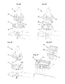
- FIG. 6 shows the delivery pistons of the cartridge according FIG. 1 in cross-sectional view
- FIG. 7 shows a turn-lock closure of a delivery piston according to FIG. 6 in a perspective view
- FIG. 8 shows the turn-lock closure according to FIG. 7 in an additional perspective view
- FIG. 9 shows a locking stopper in a perspective view according to a further embodiment
- FIG. 10 shows a lateral view of the locking stopper according to FIG. 9 .
- FIG. 11 shows a perspective view of a locking stopper inserted into a double cartridge according to FIG. 9 .
- FIG. 12 a - h shows a detail of the mixer in an enlarged perspective view
- FIG. 13 shows a second embodiment of the double cartridge according to the invention
- FIG. 14 shows the third embodiment of a double cartridge according to the invention
- FIG. 15 shows a fourth embodiment of a mixer with a cartridge prior to mounting the mixer in a perspective view
- FIG. 16 shows the embodiment according to FIG. 15 after mounting the mixer in a perspective view
- FIG. 17 shows the cartridge according to FIG. 15 prior to mounting the mixer in a perspective view
- FIG. 18 shows a cross-sectional view of the mixer according to FIG. 15 while mounting onto the cartridge
- FIG. 19 shows the mixer according to FIG. 15 after mounting onto the cartridge in a cross-sectional view
- FIG. 20 shows the fifth embodiment of a mixer with a cartridge prior to mounting the mixer in a perspective view
- FIG. 21 shows a sixth embodiment of a mixer with a cartridge prior to mounting the mixer in a perspective view
- FIG. 22 shows a seventh embodiment of a mixer with a cartridge while the mixer is being screwed in, in a perspective view
- FIG. 22A shows the enlarged detail A from FIG. 22 .
- FIG. 23 shows the mixer according to FIG. 22 while the mixer is being screwed out in a perspective view
- FIG. 23A shows the enlarged detail A from FIG. 23 .
- FIG. 24 shows an eighths embodiment of a mixer with a cartridge prior to mounting the mixer in a perspective view
- FIG. 25 shows a ninth embodiment of a mixer with a cartridge prior to mounting the mixer in a perspective view
- FIG. 26 shows a tenth embodiment of a mixture with a cartridge prior to mounting the mixer in a perspective view
- FIG. 27 shows a closure mounted on a cartridge in a partially cross-sectional view
- FIG. 27A shows the enlarged detail A from FIG. 27 .
- FIG. 28 shows an eleventh embodiment of a mixer with a cartridge prior to mounting the mixer in a perspective view
- FIG. 29 shows the mixer and the cartridge according to FIG. 28 in a further perspective view
- FIG. 30 shows a twelfth embodiment of a mixer in a cross-sectional view
- FIG. 31 shows the mixer spindle of the mixer according to FIG. 30 in a perspective view.
- the cartridge configuration illustrated in FIG. 1 essentially has one double cartridge 1 and one support cartridge 2 . Thereby, double cartridge 1 can be connected detachable with a mixer 3 .
- double cartridge 1 essentially consists of two separate supply containers 4 , 5 , whose housing is essentially cylindrical.
- the front end of supply containers 4 , 5 shown in FIG. 1 on the left is closed by a frontal wall that is dimensioned sufficiently thick to also withstand high forces during delivery of the components.
- Respectively one outlet connection piece 6 or 7 that forms an outlet opening of the respective supply container projects from this frontal wall.
- outlet connection pieces 6 , 7 are located closely adjacent, i.e. not central in the frontal wall of the supply containers. This makes it possible to design mixer 3 comparably compact, as its inlet connection pieces 3 a , 3 b are not required to have a large distance between them.
- supply containers 4 , 5 are open so that delivery pistons 8 —explained in further detail below—for sealing the supply containers can be inserted.
- Delivery pistons 8 simultaneously serve to deliver the substances or components of the compression material or the like that is contained in supply containers 4 , 5 through outlet connection pieces 6 , 7 .
- bridge 9 is designed integral with a flange-like edge 10 , which projects over the posterior end of supply containers 4 , 5 .
- a revolving groove 11 is provided in the frontal wall that serves as stop for support cartridge 2 .
- bridge 9 is provided with a catch lever 12 , which is designed integral with bridge 9 and supply containers 4 , 5 .
- catch lever 12 At the anterior end of catch lever 12 —in delivery direction—a catch hook is provided whose function will be explained in further detail below.
- Outlet connection pieces 6 , 7 of supply containers 4 , 5 can be connected with mixer 3 , which is a dynamic, i.e. an electrically operated mixer in the embodiment that is illustrated.
- mixer 3 which is a dynamic, i.e. an electrically operated mixer in the embodiment that is illustrated.
- inlet connection pieces 3 a , 2 b of the mixer are inserted into outlet connection pieces 6 , 7 .
- a guiding rib 13 is formed at mixer 3 , which projects away from the posterior end of mixer 3 toward double cartridge 1 .
- a cam 14 is provided on each outlet connection piece 6 , 7 , which jointly form a guiding channel 14 b , whose width is dimensioned in such a way that guiding rib 13 of mixer 3 is guided between the two cams 14 when mixer 3 is mounted on outlet connection pieces 6 , 7 .
- a guiding bar 14 a is additionally provided on each outlet connection piece 6 , 7 that extends in axial direction and works together with guiding rib 13 of mixer 3 .
- Cams 14 and guiding bars 14 a that jointly define guiding channel 14 b thus facilitate the precise mounting of mixer 3 by working together with guiding rib 13 .
- FIG. 5 a shows that guiding rib 13 of mixer 3 is guided in a guiding channel 14 b when the mixer is mounted, even before outlet connection pieces 6 , 7 come in contact with inlet connection pieces 3 a, b .
- This facilitates the insertion of inlet connection pieces 3 a , 3 b into outlet connection pieces 6 , 7 .
- a barrier or a stop (not shown) can be provided that prevents mounting the mixer rotated by 180°.
- such a barrier or stop can prevent that inlet connection piece 3 a comes in contact with outlet connection piece 7 , or that inlet connection piece 3 b comes in contact with outlet connection piece 6 .
- the barriers or the stop are preferably located in such a way that guiding rib 13 of mixer 3 would abut against these before the inlet connection pieces and the outlet connection pieces come in contact.
- cams 14 A further function of cams 14 can be seen in FIG. 4 , in which a locking stopper 15 is inserted into the anterior end of double cartridge 1 . It has a plate or a bar from which two pins project toward double cartridge 1 , which can be inserted into outlet connection pieces 6 , 7 in sealing manner. Locking stopper 15 further has catch hooks 16 which engage behind cams 14 on outlet connection pieces 6 , 7 , when locking stopper 15 locks both outlet connection pieces. To release the interlock, an actuation lug 17 is provided, which can be pulled toward the right in the delivery direction, i.e. in FIG. 4 toward the right, to first release the interlock and then pull locking stopper 15 out of outlet connection pieces 6 , 7 . As locking stopper 15 simultaneously locks both outlet connection pieces 6 , 7 , locking stopper 15 also provides stiffening or stabilization of double cartridge 1 , the supply containers 4 , 5 of which are, for the remainder, connected with each other by bridge 9 exclusively.
- support cartridge 2 is formed by two integrally connected metal tubes, which are open on both sides.
- the tubes that consist, for example, of aluminum have a wall thickness of approximately 1 mm to approximately 2 mm, in particular, approximately 1.3 mm.
- these tubes of support cartridge 2 are provided with an inward-projecting collar 18 at least in sections that can work together with groove 11 of double cartridge 1 to support double cartridge 1 in support cartridge 2 .
- the length of double cartridge 1 is adapted to the length of support cartridge 2 in such a way that that bridge 9 or flange-like edge 10 at the posterior end of double cartridge 1 abuts at the posterior end of the respective tube of support cartridge 2 when double cartridge 1 is inserted into support cartridge 2 .
- double cartridge 1 is supported and secured in the feed direction of delivery pistons 8 in support cartridge 2 at both of its ends.
- support cartridge 2 can be provided with a frontal wall that replaces inward-projecting collar 18 , or is supported by ft. Such a frontal wall or plate can also be screwed or glued into support cartridge 2 . As the result of a frontal wall, double cartridge 1 is supported even better in support cartridge 2 .
- the wall can either have openings that make the penetration of outlet connection pieces 6 , 7 possible, or connection pieces that can house outlet connection pieces 6 , 7 , can be provided in the wall itself.
- each tube of support cartridge 2 has a window 19 through which double cartridge 1 is visible from the outside. This also makes it possible to identify, for example, a color marking or similar coding on double cartridge 1 by looking through window 19 .
- Adapter track 20 can be inserted into this slot and fixated there by using of a screw 21 .
- Adapter track 20 can, just like support cartridge 2 , consist of metal, in particular, aluminum, or preferably, plastic.
- support cartridge 2 can be provided with a retaining clip 22 , which can be hinged rotatable at a hinge 23 in adapter track 20 .
- Retaining clip 22 has an approximately U-shaped retaining section 24 which can surround mixer 3 in sections and thus mount it on outlet connection pieces 6 , 7 .
- retaining clip 22 can be fixated in adapter track 20 or in support cartridge 2 in its position that fixates mixer 3 .
- a release knob 26 is provided that can rotate catch hook 25 into a position releasing the interlock.
- retaining clip 22 can automatically rotate into the position shown in FIG. 2 after actuating release knob 26 , in which an exchange or the installation of mixer 3 is possible.
- a catch protrusion is provided in adapter track 20 or support cartridge 2 which reaches around catch lever 12 of double cartridge 1 when it is inserted into support cartridge 2 .
- double cartridge 1 is also secured against the feed direction of delivery pistons 8 within support cartridge 2 .
- a user To remove double cartridge 1 from support cartridge 2 , a user must apply pressure to the upper section of catch lever 12 to release the interlock again.
- each delivery piston has an essentially cylindrical adapter for a turn-lock closure 32 .
- this adapter has a bead 33 at its upper edge that prevents a motion of turn-lock closure 32 in axial direction.
- turn-lock closure 32 is again pushed backward axially out of the delivery piston. Otherwise, this would lead to leakage and thus contamination of the delivery device.
- a thread or a bayonet connection can also be provided between the adapter and turn-lock closure 32 .
- the cylindrical adapter is connected with the interior space of supply containers 4 , 5 by a vent 34 . Further, in the illustrated exemplary embodiment, catch protrusions 35 are provided on the inner side of the cylindrical adapter at two diametrically opposite sides.
- Turn-lock closures 33 shown in detail in FIGS. 7 and 8 respectively have a bottom groove 36 on the bottom side in FIG. 6 , and four lateral grooves 37 extending in axial direction, of which respectively two are connected with bottom groove 36 , while the two remaining lateral grooves 37 are not connected with bottom groove 36 .
- a slot is provided to turn the turn-lock closure in the cylindrical adapter by means of a tool.
- Catch protrusions 35 on the inside of the cylindrical adapter thereby prevent an unintentional rotation of turn-lock closures 32 .
- the two lateral grooves 37 that are not connected with bottom groove 36 accept catch protrusions 35 , so that via the two lateral grooves 37 that are connected with bottom groove 36 , a venting channel is formed that is connected with the interior of supply containers 4 , 5 via vent 34 .
- turn-lock closure 32 is rotated by 90°, so that the two lateral grooves 37 that are connected with bottom groove 36 are locked by catch protrusions 35 . In this way it is possible to first let the residual air escape from the supply containers after filling supply containers 4 , 5 and inserting delivery pistons 8 , and to then completely seal the delivery pistons by actuating turn-lock closures 32 .
- FIGS. 9 to 11 show a further embodiment of a locking stopper 15 ′ in which actuating lugs 17 are offset in the direction toward the cartridge in such a way that actuating lugs 17 essentially do not protrude beyond the end of locking stopper 15 ′ that is facing away from the cartridge. This lessens the risk of damage during transport and decreases the required storage space in the outer packaging.
- reinforcement elements 38 are provided that surround or house guiding bar 14 a in such a way that the torsional stiffness of the double cartridge is improved when locking stopper 15 ′ has been inserted.
- protrusions 39 can be seen that engage with the outlet connection pieces which lock the containers of the double cartridge when locking stopper 15 ′ has been inserted.
- mixer 3 can be mounted on the cartridge system and can be fastened by retaining clip 22 .
- the mixer can also be provided with an interlocking system that is designed similar to the fastening of locking stoppers 15 or 15 ′.
- even mixer 3 can be provided with catch hooks 16 and an actuation lug 17 for detachable mounting on a cartridge system.
- the double cartridge is shown as a single package.
- individual containers such as tubular pouches that are connected with each other or can be connected with each other can form the double cartridge.
- the wall thickness of supply containers 4 or 5 is less than a tenth of the thickness of bridge 9 , for example, approximately 0.5 mm to approximately 1.0 mm, preferably approximately 0.7 mm or approximately 0.9 mm.
- the front wall can have a thickness of approximately 7 mm so that it can absorb larger forces.
- a revolving groove is formed in the inner side of the front wall, in particular, in the transition section between the front wall and the lateral wall.
- cartridge 1 according to the invention can then also be emptied to the largest degree when (delivery) pistons 8 are used with a radial outer sealing lip 28 pointing in feed direction. Sealing lip 28 can thereby dip into the groove.
- the groove offers advantages in injection molding in the transition between the thinner lateral wall and the stronger front wall.
- FIGS. 12 a to 12 h various embodiments of the adapter section of a mixer spindle 40 for housing a drive shaft (not shown) are shown.
- the illustrated inner contours of the adapter sections are intended to respectively facilitate the insertion of a drive shaft with a hexagon head, in particular, when the hexagonal head of the drive shaft is not aligned with an ideal fit for the corresponding counter contour of the receiving section, when the drive shaft is inserted into mixer spindle 40 .
- FIG. 12 a shows mixer spindle 40 of dynamically (drivable) mixer 3 with an annular (tapered) phase 41 .
- mixer spindle 40 For housing a drive shaft (not shown) torque proof, mixer spindle 40 has a hexagonal recess 42 , whereby an inside slope 43 a is provided that facilitates the insertion of the drive shaft having the hexagonal head.
- Inside slope 43 a slopes inward so that one edge of the hexagonal head of the drive shaft meets this inside slope 43 a , the drive shaft on account of continued insertion of the drive shaft into mixer spindle 40 is rotated until one surface of the hexagonal head of the drive shaft abuts at inside slope 43 a , i.e. until the hexagonal head is properly aligned with hexagonal recess 42 .
- triangles 43 b are provided between the annular (tapered) phase 41 and hexagonal recess 42 , which facilitate the insertion of the drive shaft having a hexagonal head. Due to the upwardly inclined surfaces of triangles 43 in FIG. 12 b , in a possible misalignment of the hexagonal head, it can be rotated by continued insertion of the drive shaft into mixer spindle 40 until the hexagonal head is aligned with hexagonal recess 42 .
- FIG. 12 c A similar embodiment is shown in FIG. 12 c , whereby instead of triangles 43 b , at several positions distributed over the circumference, a tapered inlet 43 c is provided respectively.
- FIG. 12 d one-sided inlet inclines 43 d are provided that allow rotation of the hexagonal head in only one direction.
- the tapered phase 41 is elongated with respect to the previously cited embodiments until it directly forms an incline merging into hexagonal recess 42 .
- FIG. 12 f largely corresponds to FIG. 12 b , whereby only one triangle 43 b is provided.
- FIG. 12 h largely corresponds to that of FIG. 12 d , whereby only two saw tooth-like tips 43 d are provided which are, however, facing each other with their inclined surfaces.
- FIG. 12 g is based on the embodiment of FIG. 12 e , whereby subsequent to the tapered phase 41 , first a cylindrical guiding section 43 e and subsequent to it a further tapered section 43 f is provided, which then transitions into hexagonal recess 42 .
- annular phase 41 first centers and guides the drive shaft.
- Triangles 43 then guide the edges of the hexagonal head of the drive shaft into the hexagonal recess contour 42 of mixer spindle 40 while the mixer is at standstill so that it must rotate a maximum of 1/12 to receive the hexagonal head.
- double cartridge 1 can also have a thread 44 , which is used for fastening mixer 3 .
- a double cartridge is shown in which protrusions 14 that are provided on outlet connection pieces 6 , 7 are integrally formed with a ring or ring segments that surround both outlet connection pieces.
- This ring or these ring segments have an outer thread 44 on which, for example, (not shown) a mixer 3 can be mounted by using a coupling nut.
- FIG. 14 A similar embodiment is shown in FIG. 14 .
- the ring or collar 1 b at the end of outlet connection pieces 6 , 7 is provided with an inner thread 44 , into which a corresponding outer thread 45 can be screwed onto the housing of mixer 3 .
- an interior insert of the mixer that also has inlet connection pieces 3 a , 3 b of the mixer is housed rotatable in the housing of mixer 3 , so that the outer housing can be rotated relative to the interior insert for screwing on the mixer.
- Collar 1 b that carries inner thread 44 can be formed integral with a plate 1 a , at which the outlet connection pieces end flush.
- Protrusions 14 of the two outlet connection pieces 6 , 7 thus jointly form plate 1 a , whereby guiding rib 13 of the mixer engages with an opening or a guiding channel 14 b of the plate in order to align the mixer or its internal insert with the double cartridge in such a way that the inlet connection pieces of the mixer meet the outlet connection pieces of the cartridge.
- the width of guiding rib 13 is larger than the diameter of the larger outlet connection piece 6 so that guiding rib 13 cannot accidentally be inserted into an outlet connection piece.
- FIGS. 15 to 19 show an embodiment that is similar to FIG. 14 , in which instead of a guiding rib 13 , two guiding ribs 13 are provided at a distance to each other that can be inserted into an opening or a guiding channel 14 b of plate 1 a respectively.
- the tips of guiding ribs 13 can thereby protrude from plate 1 a of the cartridge on the side facing away from mixer 3 , when the mixer is completely mounted on the cartridge.
- a color marking can also be used to display the mounting of the mixer to the user.
- a mixer 3 according to the invention is preferably designed with a mixer housing 3 c that bears outer thread 45 and forms a coupling section 3 d that is freely rotatable—i.e. can be rotated at will in both directions—in which a mixer housing 3 c is mounted.
- coupling section 3 d has the at least one guiding rib 13 and inlet connection pieces 3 a and 3 b and locks mixer housing 3 c on the cartridge side.
- mixer spindle 40 can be mounted in coupling section 3 d .
- the free rotatability of the mixer housing relative to the coupling section affords the advantage that the mixer can be mounted on the cartridge in any position and the cartridge and the coupling section can freely align with each other without requiring the user to have direct visual contact, for example, with the inlet connection pieces and/or the guiding rib.
- screwing in the mixer becomes possible, while the inlet and outlet connection pieces and the guiding rib and the guiding channel are already engaged.
- FIG. 20 shows a similar design of mixer 3 with an outer thread 45 , whereby the protrusions or bars that form thread 45 extend only around a part of the circumference of the mixer and the individual threaded bar segments do not overlap each other. Rather, free spaces remain between the individual threaded segments.
- the size of the free spaces is thereby selected in such a way that the threaded segments of the outer thread fit into the free spaces between the segments of the inner thread and the reverse.
- Threads 44 , 45 are thereby constructed in such a way that these disengage when mixer 3 is screwed off or out, because the segments of outer thread 45 engaging behind the respective thread segments of inner thread 44 distance themselves from the respective lower surface of the threaded bar segments of inner thread 44 .
- mixer 3 can at first not be lifted off the cartridge or plate 1 a by releasing the threaded engagement into which outlet connection pieces 6 , 7 discharge.
- an inside slope 46 is designed that is defined by the head surfaces of several axially extending bars.
- FIG. 21 shows a modification of the embodiment of FIG. 20 , whereby the threaded segments of inner thread 44 and of outer thread 45 are in turn designed with corresponding free spaces.
- Mixer 3 is then screwed into the ring of the cartridge just like it was explained above relative to FIG. 20 .
- inside slopes 46 are provided that can be respectively connected with the corresponding threaded segment of inner thread 44 by an axially extending bar at the inner wall of ring 1 b .
- axial bars 47 project in the direction of the cartridge on the outer surface of the mixer housing. The ends on the side of the cartridge (bottom in FIG. 21 ) of these bars 47 reach up to the cartridge-side edge of the mixer housing, or can extend slightly beyond such.
- FIGS. 22 to 23A A further embodiment is shown in FIGS. 22 to 23A .
- the fundamental structure of the cartridge and the mixer thereby substantially corresponds to the embodiment shown in FIG. 14 .
- threads 44 , 45 on the mixer housing or in ring 1 b of the cartridge are, however, designed in such a way that the thread turns, i.e. the free spaces between the threaded segments protruding from the inner wall of ring 1 b or from the outer wall of the mixer housing are selected broader than the width of the threaded segments.
- the thread turns can have a width of approximately 2.3 mm, while the threaded segments only have a width of 1.55 mm.
- the outer diameter of the threaded segments of the outer thread can be defined smaller than the inner diameter of ring 1 b in the thread turns and the inner diameter of the threaded segments of the inner thread defined larger than the outer diameter of the mixer housing.
- a radial clearance is also created in the section of threads 44 , 45 between ring 1 b of the cartridge and the mixer housing, so that mixer 3 is guided in the cartridge exclusively by guiding rib(s) 13 and guiding channel 14 b , before inlet connection pieces 3 a , 3 b and outlet connection pieces 6 , 7 also engage.
- This design of the thread consequently avoids double fits and the forces required for screwing in and for screwing out can be reduced further.
- outer thread 45 of the mixer housing can go up to the edge of the mixer housing on the cartridge side.
- FIGS. 24 and 25 show in the embodiments in FIGS. 24 and 25 , whereby the mixer in FIG. 24 has three threaded bar segments that sometimes overlap, which respectively extend approximately 120°, while the mixer according to FIG. 25 has two threaded bar segments that do not overlap, which respectively extend approximately 180°.
- the contact between threads 44 , 45 while screwing in or screwing out the mixer as was explained relative to FIGS. 22 and 23A , can also take place with low friction, whereby respectively only one surface of the threads make contact.
- FIG. 26 A further embodiment is shown in FIG. 26 , the structure of which substantially corresponds to the embodiment in FIG. 21 .
- inside slope 46 in the transition section between plate 1 a into which outlet connection pieces 6 , 7 discharge and ring 1 b or the flange that bears inner thread 44 are omitted, so that mixer 3 , although it can be unlocked by such by a rotation of the mixer housing relative to the cartridge, the mixer, however, is not lifted from the cartridge by continued rotation. Rather, mixer 3 must be pulled off the cartridge via threads 44 , 45 after the interlock with the cartridge is released.
- the additional axial bars 48 on the inner side of ring 1 b are shown that limit—together with bars 47 —the rotatability of mixer 3 relative to the cartridge when releasing the connection.
- FIGS. 27 and 27A A further locking stopper 15 is shown in FIGS. 27 and 27A that in turn has the protrusions that lock outlet connection pieces 6 , 7 and is housed with a cylindrical section within the ring or collar 1 b of the cartridge.
- hooks 49 are provided that can engage behind the free ends of the threaded bar segments of inner thread 44 .
- locking stopper 15 can be snapped onto the cartridge.
- locking stopper 15 is rotated relative to the cartridge so that hooks 49 release from the threaded bar segments.
- the free end of hook 49 on the cartridge side can come in contact with the adjacent (in FIG. 27A bottom) threaded bar segment, so that as a result of the rotation, locking stopper 15 is also lifted off the cartridge.
- FIGS. 28 and 29 show a further embodiment that substantially corresponds to FIG. 24 , i.e. threads 44 , 45 are respectively designed with threaded bar segments that overlap in sections.
- outlet connection pieces 6 , 7 of a cartridge can also project beyond plate 1 a , as is indicated, for example, in FIGS. 28 and 29 .
- a guiding protrusion 14 a can be formed that facilitates the insertion of guiding rib 13 into slot 14 b .
- this additional guiding protrusion 14 a has two funnel-shaped sections facing each other on both sides of guiding slot 14 b that are connected with each other by a curved section. Additional guiding protrusion 14 a can thereby be either directly connected with outlet connection pieces 6 , 7 , or located at a small distance from such.
- ribs can be seen on plate 1 a in FIG. 29 , which are opposite to guiding slot 14 b . These prevent mounting mixer 3 on the cartridge in the wrong direction.
- the impermeability between the cartridge and the mixer is especially important in modern delivery systems (cartridge, mixer and delivery device for driving the pistons in the cartridge). According to the invention, this is also achieved, for example, in the embodiments of FIGS. 28 and 29 thereby, that by a thread with several thread turns, a large axial relative motion between the mixer and the cartridge is generated during the screwing in process.
- the mixer can be firmly pressed onto the cartridge so that on the one hand, the inlet and outlet connection pieces are connected with each other in a sealing manner, and on the other hand, even within the mixer itself, in particular, between mixer housing 3 c and coupling section 3 d , the impermeability is improved.
- the thread turns which are preferably offset by 120° and overlap each other, also absorb the axially occurring forces well.
- this threaded connection also requires that the coupling section and the mixer housing are freely rotatable with respect to each other. This in turn has the effect of simplifying the alignment of the inlet and outlet connection pieces when mounting mixer 3 , first the guiding rib engages with the guiding channel and thus guides and aligns the mixer.
- FIGS. 30 and 31 show a further aspect of a mixer 3 according to the invention, in which inlet connection pieces 3 a , 3 b discharge at offset planes into the mixing chamber formed in mixer housing 3 c .
- the inlet for the mass entering through inlet connection piece 3 b is closer to the cartridge than the inlet for the mass entering through inlet connection piece 3 a .
- an annular space is formed in the interior of the mixer that surrounds mixer spindle 40 , in which the mass entering through inlet connection piece 3 b can be captured before it reaches into the mixing chamber. This prevents a bad mixing result at the beginning of the mixing process.
- Mixing blades 53 of the mixer spindle and the remaining embodiment, for example, of the connection section with a drive shaft, can be designed as shown in FIGS. 12 a to 12 h .
Landscapes
- Chemical Kinetics & Catalysis (AREA)
- Chemical & Material Sciences (AREA)
- Engineering & Computer Science (AREA)
- Mechanical Engineering (AREA)
- Health & Medical Sciences (AREA)
- Life Sciences & Earth Sciences (AREA)
- Heart & Thoracic Surgery (AREA)
- Hematology (AREA)
- Biomedical Technology (AREA)
- Animal Behavior & Ethology (AREA)
- General Health & Medical Sciences (AREA)
- Public Health (AREA)
- Veterinary Medicine (AREA)
- Anesthesiology (AREA)
- Vascular Medicine (AREA)
- Dental Tools And Instruments Or Auxiliary Dental Instruments (AREA)
- Coating Apparatus (AREA)
Applications Claiming Priority (10)
| Application Number | Priority Date | Filing Date | Title |
|---|---|---|---|
| DE102010049378 | 2010-10-26 | ||
| DE102010049378.3A DE102010049378B4 (de) | 2010-10-26 | 2010-10-26 | Kartuschenanordnung mit einer Doppelkartusche |
| DE102010049378.3 | 2010-10-26 | ||
| DE202011002407U DE202011002407U1 (de) | 2010-10-26 | 2011-02-04 | Doppelkartusche, Mischer hierfür und Kombination aus Doppelkartusche und Mischer |
| DE202011002407.5 | 2011-02-04 | ||
| DE202011002407U | 2011-02-04 | ||
| DE102011111046.5 | 2011-08-24 | ||
| DE102011111046 | 2011-08-24 | ||
| DE102011111046 | 2011-08-24 | ||
| PCT/EP2011/068784 WO2012055926A1 (de) | 2010-10-26 | 2011-10-26 | Doppelkartusche, mischer hierfür und kombination aus doppelkartusche und mischer |
Publications (2)
| Publication Number | Publication Date |
|---|---|
| US20130265846A1 US20130265846A1 (en) | 2013-10-10 |
| US9522368B2 true US9522368B2 (en) | 2016-12-20 |
Family
ID=44906070
Family Applications (1)
| Application Number | Title | Priority Date | Filing Date |
|---|---|---|---|
| US13/879,773 Active 2033-08-08 US9522368B2 (en) | 2010-10-26 | 2011-10-26 | Double cartridge, mixer therefor and combination of double cartridge and mixer |
Country Status (6)
| Country | Link |
|---|---|
| US (1) | US9522368B2 (de) |
| EP (1) | EP2632607B1 (de) |
| JP (1) | JP5746356B2 (de) |
| BR (1) | BR112013010171B1 (de) |
| ES (1) | ES2666240T3 (de) |
| WO (1) | WO2012055926A1 (de) |
Cited By (4)
| Publication number | Priority date | Publication date | Assignee | Title |
|---|---|---|---|---|
| US20160296963A1 (en) * | 2015-04-13 | 2016-10-13 | Nordson Corporation | Fluid cartridge system and method of using a fluid cartridge system |
| US20170156820A1 (en) * | 2014-06-23 | 2017-06-08 | Sulzer Mixpac Ag | Syringe for multi-component materials, method of activating a syringe, mixing and dispensing apparatus and multi-component cartridge |
| USD792177S1 (en) * | 2016-02-25 | 2017-07-18 | Phillip Phung-I Ho | Head for a dual-cartridge dispenser |
| US20170252715A1 (en) * | 2016-03-03 | 2017-09-07 | Heraeus Medical Gmbh | Storage and mixing system for pasty cement components and method therefor |
Families Citing this family (21)
| Publication number | Priority date | Publication date | Assignee | Title |
|---|---|---|---|---|
| EP2520360B1 (de) * | 2011-05-02 | 2014-07-16 | Sulzer Mixpac AG | Mischer zum Mischen von mindestens zwei fliessfähigen Komponenten sowie Austragsvorrichtung |
| CN103998149B (zh) * | 2011-10-17 | 2017-03-29 | 苏舍米克斯帕克有限公司 | 筒和多组分筒 |
| BR112015009044A2 (pt) * | 2012-10-23 | 2017-07-04 | Sulzer Mixpac Ag | dispositivo de descarga |
| KR101369005B1 (ko) * | 2013-06-27 | 2014-03-04 | 송림기업 주식회사 | 케미컬 앵커 인젝션 카트리지 |
| US9387151B2 (en) | 2013-08-20 | 2016-07-12 | Anutra Medical, Inc. | Syringe fill system and method |
| BR112016003310B1 (pt) * | 2013-08-29 | 2022-08-16 | Sanofi-Aventis Deutschland Gmbh | Dispositivo de aplicação de fármaco |
| KR101406068B1 (ko) * | 2013-09-05 | 2014-06-11 | (주)디엑스엠 | 디스펜서용 믹싱팁 |
| USD763433S1 (en) * | 2014-06-06 | 2016-08-09 | Anutra Medical, Inc. | Delivery system cassette |
| USD774182S1 (en) | 2014-06-06 | 2016-12-13 | Anutra Medical, Inc. | Anesthetic delivery device |
| US20170274414A1 (en) * | 2014-09-02 | 2017-09-28 | Sika Technology Ag | Application device for applying gel-like and/or paste-like compositions and application unit for an application device of this type |
| KR101652278B1 (ko) * | 2015-05-14 | 2016-09-09 | 박동신 | 인상재 디스펜서 |
| US10281074B2 (en) | 2016-01-14 | 2019-05-07 | Nordson Corporation | Adapters for connecting a separated-outlet fluid cartridge to a single-inlet mixer, and related methods |
| US10641423B2 (en) * | 2016-06-09 | 2020-05-05 | Nordson Corporation | Adapters for connecting a separated-outlet fluid cartridge to a single-inlet mixer, and related methods |
| CN107213821A (zh) * | 2017-07-14 | 2017-09-29 | 无锡市跨克微营养素有限公司 | 内置双筒溢浆浆液混匀装置 |
| USD896970S1 (en) * | 2018-01-31 | 2020-09-22 | Kettenbach Gmbh & Co. Kg | Medical cartridge |
| CN110252174B (zh) * | 2019-07-01 | 2021-09-07 | 河南城建学院 | 一种建筑装饰用涂料配制装置 |
| DE102019119161A1 (de) * | 2019-07-15 | 2021-01-21 | Kulzer Gmbh | Dynamischer Mischer zum benutzerfreundlichen Einlegen in eine Mischapparatur |
| EP3771495A1 (de) * | 2019-07-29 | 2021-02-03 | Sulzer Mixpac AG | Austossanordnung, komponente, zubehör, verfahren zum verbinden eines zubehörs mit einer komponente und system |
| CN112295493A (zh) * | 2020-10-10 | 2021-02-02 | 河南恒发建筑材料有限公司 | 一种石膏生产用粉浆料搅拌设备 |
| CN113198096A (zh) * | 2021-05-08 | 2021-08-03 | 商丘医学高等专科学校 | 一种痤疮皮肤护理用药物涂抹装置 |
| GB2624247A (en) * | 2022-11-14 | 2024-05-15 | Medmix Switzerland Ag | Cartridge assembly and method of assembling a cartridge assembly |
Citations (46)
| Publication number | Priority date | Publication date | Assignee | Title |
|---|---|---|---|---|
| US4046145A (en) * | 1976-06-29 | 1977-09-06 | American Hospital Supply Corporation | Syringe connector |
| US4771919A (en) * | 1987-10-28 | 1988-09-20 | Illinois Tool Works Inc. | Dispensing device for multiple components |
| EP0302819A2 (de) | 1987-07-30 | 1989-02-08 | HILTI Aktiengesellschaft | Kartuschenmagazin für fliessfähige Massen |
| US4898588A (en) * | 1988-10-17 | 1990-02-06 | Roberts Christopher W | Hypodermic syringe splatter shield |
| US4974756A (en) * | 1989-07-14 | 1990-12-04 | Minnesota Mining And Manufacturing Company | Double barrel dispensing container and cap therefor |
| US4981241A (en) | 1987-06-10 | 1991-01-01 | Keller Wilhelm A | Double delivery cartridge for two component masses |
| US5228599A (en) * | 1990-07-20 | 1993-07-20 | Keller Wilhelm A | Multiple dispensing cartridge for multiple-component substances |
| US5249709A (en) * | 1989-10-16 | 1993-10-05 | Plas-Pak Industries, Inc. | Cartridge system for dispensing predetermined ratios of semi-liquid materials |
| US5290222A (en) * | 1991-10-15 | 1994-03-01 | Jiyu Feng | Injection port connector with rotatable locking lug |
| US5328462A (en) * | 1993-09-03 | 1994-07-12 | Ultradent Products, Inc. | Methods and apparatus for mixing and dispensing multi-part compositions |
| US5383858A (en) * | 1992-08-17 | 1995-01-24 | Medrad, Inc. | Front-loading medical injector and syringe for use therewith |
| US5413253A (en) * | 1993-12-06 | 1995-05-09 | Coltene/Whaledent, Inc. | Static mixer |
| US5443183A (en) * | 1993-11-18 | 1995-08-22 | Jacobsen; Kenneth H. | Unitary check valve |
| US5535922A (en) | 1994-11-29 | 1996-07-16 | Tah Industries, Inc. | Caulking gun dispensing module for multi-component cartridge |
| DE19500782A1 (de) | 1995-01-13 | 1996-07-18 | Bayer Ag | Vorrichtung zum Mischen und Ausbringen einer Formmasse |
| US5643206A (en) * | 1993-09-03 | 1997-07-01 | Ultradent Products, Inc. | Methods and apparatus for mixing and dispensing multi-part compositions |
| US5819988A (en) * | 1997-04-01 | 1998-10-13 | Sawhney; Ravi K. | Double-barreled syringe with detachable locking mixing tip |
| US5918772A (en) * | 1995-03-13 | 1999-07-06 | Wilhelm A. Keller | Bayonet fastening device for the attachment of an accessory to a multiple component cartridge or dispensing device |
| US6065645A (en) * | 1997-04-01 | 2000-05-23 | Discus Dental Impressions, Inc. | Double-barreled syringe with detachable locking mixing tip |
| US6135631A (en) * | 1997-06-18 | 2000-10-24 | Keller; Wilhelm A. | Mixer for multiple component dispensing cartridge |
| US6309372B1 (en) * | 1999-07-16 | 2001-10-30 | Ultradent Products, Inc. | Integrated mixing and dispensing apparatus |
| US6328182B1 (en) * | 1999-07-23 | 2001-12-11 | Sulzer Chemtech Ag | Two-component cartridge |
| US6398761B1 (en) * | 2001-01-19 | 2002-06-04 | Ultradent Products, Inc. | Double syringe barrels with ported delivery ends |
| US20020170926A1 (en) * | 2001-05-21 | 2002-11-21 | Horner Terry A. | Two-component cartridge system |
| US6592251B2 (en) * | 2001-01-26 | 2003-07-15 | Howmedica Osteonics Corp. | Cement mixing and dispensing device |
| US20030183659A1 (en) | 2002-04-02 | 2003-10-02 | Duraswitch | Impact absorbing system for a flat switch panel |
| US20040068234A1 (en) * | 2002-10-03 | 2004-04-08 | Jeff Martin | Bone graft particle delivery apparatus and method |
| US6936032B1 (en) * | 1999-08-05 | 2005-08-30 | Becton, Dickinson And Company | Medication delivery pen |
| DE102004030407A1 (de) | 2004-06-23 | 2006-01-19 | Heraeus Kulzer Gmbh | Kartusche für pastöse Materialien |
| DE202006004738U1 (de) | 2006-03-24 | 2006-06-01 | Euro-Lock-Vertriebs-Gmbh | Vorrichtung für das Mischen zweier Fluide |
| US7115234B2 (en) * | 1998-12-04 | 2006-10-03 | Symyx Technologies, Inc. | Parallel semi-continuous or continuous reactor system |
| US20070095865A1 (en) | 2005-10-28 | 2007-05-03 | Chick Mark C | Fastener engaging caulking tube nozzle |
| US20070175921A1 (en) * | 2004-07-08 | 2007-08-02 | Mixpac Systems Ag | Dispensing device for single use |
| WO2007098624A1 (en) | 2006-03-01 | 2007-09-07 | Medmix Systems Ag | Two-part double syringe |
| WO2008009143A1 (en) | 2006-07-17 | 2008-01-24 | Medmix Systems Ag | Dispensing appliance for a multiple cartridge |
| EP1972387A2 (de) | 2007-03-22 | 2008-09-24 | GC Corporation | Mischspitze |
| WO2008113196A1 (en) | 2007-03-19 | 2008-09-25 | Sulzer Mixpac Ag | Dispensing assembly having removably attachable accessories |
| WO2008130971A1 (en) | 2007-04-19 | 2008-10-30 | 3M Innovative Properties Company | Dispensing device with locking member |
| DE102007044983A1 (de) | 2007-09-19 | 2009-04-09 | Kettenbach Gmbh & Co. Kg | Austragvorrichtung |
| US20090152300A1 (en) * | 2007-12-14 | 2009-06-18 | Discus Dental, Llc | Multi-Compartment Devices Having Dispensing Tips |
| WO2009124407A1 (en) | 2008-04-10 | 2009-10-15 | Medmix Systems Ag | Connectable double syringe |
| WO2010020061A1 (de) | 2008-08-22 | 2010-02-25 | Medmix Systems Ag | Anschlussstück für austragvorrichtung |
| US20110114668A1 (en) | 2007-09-19 | 2011-05-19 | Kettenbach Gmbh & Co. Kg | Dispensing Device |
| EP2335641A1 (de) | 2009-12-18 | 2011-06-22 | Seil Global Corporation | Struktur zum Verbinden einer Mischdüse mit einer Kartusche |
| US20120179108A1 (en) * | 2009-06-24 | 2012-07-12 | Becton Dickinson France | Luer connector |
| US20140198602A1 (en) * | 2011-08-24 | 2014-07-17 | Kettenbach Gmbh & Co. Kg | Mixer |
Family Cites Families (4)
| Publication number | Priority date | Publication date | Assignee | Title |
|---|---|---|---|---|
| ES2164750T3 (es) | 1995-03-07 | 2002-03-01 | Wilhelm A Keller | Dispositivo de fijacion por bayoneta para sujetar un accesorio a un cartucho de componentes multiples o dispositivo distribuidor. |
| EP1440737A1 (de) | 2003-01-24 | 2004-07-28 | Mixpac Systems AG | Austraganordnung mit einem Austraggerät für mindestens zwei Komponenten |
| SI1943012T1 (sl) | 2005-10-07 | 2010-05-31 | Sulzer Mixpac Ag | Dinamični mešalnik |
| EP2485852B1 (de) | 2009-10-06 | 2013-10-30 | Medmix Systems AG | Austraganordnung mit einer verbindungsvorrichtung zwischen einer mehrkomponenten-kartusche und einem zubehörteil |
-
2011
- 2011-10-26 BR BR112013010171-7A patent/BR112013010171B1/pt active IP Right Grant
- 2011-10-26 JP JP2013535419A patent/JP5746356B2/ja active Active
- 2011-10-26 WO PCT/EP2011/068784 patent/WO2012055926A1/de active Application Filing
- 2011-10-26 ES ES11778554.3T patent/ES2666240T3/es active Active
- 2011-10-26 US US13/879,773 patent/US9522368B2/en active Active
- 2011-10-26 EP EP11778554.3A patent/EP2632607B1/de active Active
Patent Citations (53)
| Publication number | Priority date | Publication date | Assignee | Title |
|---|---|---|---|---|
| US4046145A (en) * | 1976-06-29 | 1977-09-06 | American Hospital Supply Corporation | Syringe connector |
| US4981241A (en) | 1987-06-10 | 1991-01-01 | Keller Wilhelm A | Double delivery cartridge for two component masses |
| EP0302819A2 (de) | 1987-07-30 | 1989-02-08 | HILTI Aktiengesellschaft | Kartuschenmagazin für fliessfähige Massen |
| US4871090A (en) | 1987-07-30 | 1989-10-03 | Hilti Aktiengesellschaft | Cartridge assembly for flowable masses |
| US4771919A (en) * | 1987-10-28 | 1988-09-20 | Illinois Tool Works Inc. | Dispensing device for multiple components |
| US4898588A (en) * | 1988-10-17 | 1990-02-06 | Roberts Christopher W | Hypodermic syringe splatter shield |
| US4974756A (en) * | 1989-07-14 | 1990-12-04 | Minnesota Mining And Manufacturing Company | Double barrel dispensing container and cap therefor |
| US5249709A (en) * | 1989-10-16 | 1993-10-05 | Plas-Pak Industries, Inc. | Cartridge system for dispensing predetermined ratios of semi-liquid materials |
| US5228599A (en) * | 1990-07-20 | 1993-07-20 | Keller Wilhelm A | Multiple dispensing cartridge for multiple-component substances |
| US5290222A (en) * | 1991-10-15 | 1994-03-01 | Jiyu Feng | Injection port connector with rotatable locking lug |
| US5383858B1 (en) * | 1992-08-17 | 1996-10-29 | Medrad Inc | Front-loading medical injector and syringe for use therewith |
| US5383858A (en) * | 1992-08-17 | 1995-01-24 | Medrad, Inc. | Front-loading medical injector and syringe for use therewith |
| US5328462A (en) * | 1993-09-03 | 1994-07-12 | Ultradent Products, Inc. | Methods and apparatus for mixing and dispensing multi-part compositions |
| US5643206A (en) * | 1993-09-03 | 1997-07-01 | Ultradent Products, Inc. | Methods and apparatus for mixing and dispensing multi-part compositions |
| US5443183A (en) * | 1993-11-18 | 1995-08-22 | Jacobsen; Kenneth H. | Unitary check valve |
| US5413253A (en) * | 1993-12-06 | 1995-05-09 | Coltene/Whaledent, Inc. | Static mixer |
| US5535922A (en) | 1994-11-29 | 1996-07-16 | Tah Industries, Inc. | Caulking gun dispensing module for multi-component cartridge |
| DE19500782A1 (de) | 1995-01-13 | 1996-07-18 | Bayer Ag | Vorrichtung zum Mischen und Ausbringen einer Formmasse |
| US5875928A (en) | 1995-01-13 | 1999-03-02 | Bayer Aktiengesellschaft | Device for mixing and discharging a molding composition |
| US5918772A (en) * | 1995-03-13 | 1999-07-06 | Wilhelm A. Keller | Bayonet fastening device for the attachment of an accessory to a multiple component cartridge or dispensing device |
| US5819988A (en) * | 1997-04-01 | 1998-10-13 | Sawhney; Ravi K. | Double-barreled syringe with detachable locking mixing tip |
| US6065645A (en) * | 1997-04-01 | 2000-05-23 | Discus Dental Impressions, Inc. | Double-barreled syringe with detachable locking mixing tip |
| US6135631A (en) * | 1997-06-18 | 2000-10-24 | Keller; Wilhelm A. | Mixer for multiple component dispensing cartridge |
| US7115234B2 (en) * | 1998-12-04 | 2006-10-03 | Symyx Technologies, Inc. | Parallel semi-continuous or continuous reactor system |
| US6309372B1 (en) * | 1999-07-16 | 2001-10-30 | Ultradent Products, Inc. | Integrated mixing and dispensing apparatus |
| US6328182B1 (en) * | 1999-07-23 | 2001-12-11 | Sulzer Chemtech Ag | Two-component cartridge |
| US6936032B1 (en) * | 1999-08-05 | 2005-08-30 | Becton, Dickinson And Company | Medication delivery pen |
| US6398761B1 (en) * | 2001-01-19 | 2002-06-04 | Ultradent Products, Inc. | Double syringe barrels with ported delivery ends |
| US6592251B2 (en) * | 2001-01-26 | 2003-07-15 | Howmedica Osteonics Corp. | Cement mixing and dispensing device |
| US20020170926A1 (en) * | 2001-05-21 | 2002-11-21 | Horner Terry A. | Two-component cartridge system |
| WO2002094681A1 (en) | 2001-05-21 | 2002-11-28 | Tah Industries, Inc. | Two-component cartridge system |
| US20030183659A1 (en) | 2002-04-02 | 2003-10-02 | Duraswitch | Impact absorbing system for a flat switch panel |
| US20040068234A1 (en) * | 2002-10-03 | 2004-04-08 | Jeff Martin | Bone graft particle delivery apparatus and method |
| DE102004030407A1 (de) | 2004-06-23 | 2006-01-19 | Heraeus Kulzer Gmbh | Kartusche für pastöse Materialien |
| US20060138166A1 (en) | 2004-06-23 | 2006-06-29 | Heraeus Kulzer Gmbh | Cartridge for pasty materials |
| US20070175921A1 (en) * | 2004-07-08 | 2007-08-02 | Mixpac Systems Ag | Dispensing device for single use |
| US20070095865A1 (en) | 2005-10-28 | 2007-05-03 | Chick Mark C | Fastener engaging caulking tube nozzle |
| WO2007098624A1 (en) | 2006-03-01 | 2007-09-07 | Medmix Systems Ag | Two-part double syringe |
| DE202006004738U1 (de) | 2006-03-24 | 2006-06-01 | Euro-Lock-Vertriebs-Gmbh | Vorrichtung für das Mischen zweier Fluide |
| WO2008009143A1 (en) | 2006-07-17 | 2008-01-24 | Medmix Systems Ag | Dispensing appliance for a multiple cartridge |
| US20100102088A1 (en) | 2007-03-19 | 2010-04-29 | Sulzer Mixpac Ag | Dispensing Assembly Having Removably Attachable Accessories |
| WO2008113196A1 (en) | 2007-03-19 | 2008-09-25 | Sulzer Mixpac Ag | Dispensing assembly having removably attachable accessories |
| EP1972387A2 (de) | 2007-03-22 | 2008-09-24 | GC Corporation | Mischspitze |
| US20100089949A1 (en) | 2007-04-19 | 2010-04-15 | 3M Innovative Properties Company | Dispensing device with locking member |
| WO2008130971A1 (en) | 2007-04-19 | 2008-10-30 | 3M Innovative Properties Company | Dispensing device with locking member |
| DE102007044983A1 (de) | 2007-09-19 | 2009-04-09 | Kettenbach Gmbh & Co. Kg | Austragvorrichtung |
| US20110114668A1 (en) | 2007-09-19 | 2011-05-19 | Kettenbach Gmbh & Co. Kg | Dispensing Device |
| US20090152300A1 (en) * | 2007-12-14 | 2009-06-18 | Discus Dental, Llc | Multi-Compartment Devices Having Dispensing Tips |
| WO2009124407A1 (en) | 2008-04-10 | 2009-10-15 | Medmix Systems Ag | Connectable double syringe |
| WO2010020061A1 (de) | 2008-08-22 | 2010-02-25 | Medmix Systems Ag | Anschlussstück für austragvorrichtung |
| US20120179108A1 (en) * | 2009-06-24 | 2012-07-12 | Becton Dickinson France | Luer connector |
| EP2335641A1 (de) | 2009-12-18 | 2011-06-22 | Seil Global Corporation | Struktur zum Verbinden einer Mischdüse mit einer Kartusche |
| US20140198602A1 (en) * | 2011-08-24 | 2014-07-17 | Kettenbach Gmbh & Co. Kg | Mixer |
Non-Patent Citations (2)
| Title |
|---|
| European Office Action issued in European Patent Application No. 11778554.3 dated Oct. 9, 2014. |
| Form PCT/IB/338, Notification of Transmittal of Translation of the International Preliminary Report on Patentability. |
Cited By (8)
| Publication number | Priority date | Publication date | Assignee | Title |
|---|---|---|---|---|
| US20170156820A1 (en) * | 2014-06-23 | 2017-06-08 | Sulzer Mixpac Ag | Syringe for multi-component materials, method of activating a syringe, mixing and dispensing apparatus and multi-component cartridge |
| US10335249B2 (en) * | 2014-06-23 | 2019-07-02 | Sulzer Mixpac Ag | Syringe for multi-component materials, method of activating a syringe, mixing and dispensing apparatus and multi-component cartridge |
| US20160296963A1 (en) * | 2015-04-13 | 2016-10-13 | Nordson Corporation | Fluid cartridge system and method of using a fluid cartridge system |
| US10099838B2 (en) * | 2015-04-13 | 2018-10-16 | Nordson Corporation | Fluid cartridge system and method of using a fluid cartridge system |
| US10351328B2 (en) * | 2015-04-13 | 2019-07-16 | Nordson Corporation | Fluid cartridge system and method of using a fluid cartridge system |
| USD792177S1 (en) * | 2016-02-25 | 2017-07-18 | Phillip Phung-I Ho | Head for a dual-cartridge dispenser |
| US20170252715A1 (en) * | 2016-03-03 | 2017-09-07 | Heraeus Medical Gmbh | Storage and mixing system for pasty cement components and method therefor |
| US10086343B2 (en) * | 2016-03-03 | 2018-10-02 | Heraeus Medical Gmbh | Storage and mixing system for pasty cement components and method therefor |
Also Published As
| Publication number | Publication date |
|---|---|
| JP5746356B2 (ja) | 2015-07-08 |
| US20130265846A1 (en) | 2013-10-10 |
| BR112013010171B1 (pt) | 2020-12-22 |
| EP2632607B1 (de) | 2018-02-21 |
| JP2013542017A (ja) | 2013-11-21 |
| ES2666240T3 (es) | 2018-05-03 |
| BR112013010171A2 (pt) | 2016-09-13 |
| WO2012055926A1 (de) | 2012-05-03 |
| EP2632607A1 (de) | 2013-09-04 |
Similar Documents
| Publication | Publication Date | Title |
|---|---|---|
| US9522368B2 (en) | Double cartridge, mixer therefor and combination of double cartridge and mixer | |
| US9797511B2 (en) | Piston and cartridge arrangement having said piston | |
| US8978930B2 (en) | Container | |
| US9168108B2 (en) | Dispensing device | |
| US8142402B2 (en) | Multichamber ampoule for dispensing a mixture consisting of several substances | |
| US10413384B2 (en) | Container for storing and dispensing at least one component and method therefor | |
| US8733593B2 (en) | Cartridge dispenser with rotational lock | |
| EP1656215B1 (de) | Einzeldosisspritze für ein mehrkomponentenmaterial | |
| CN102413789B (zh) | 牙科物质的分配装置 | |
| US9272252B2 (en) | System composed of cartridges and mixers | |
| US9550159B2 (en) | Mixer and dispensing device | |
| CA2602217C (en) | A multicomponent cartridge | |
| US9283060B2 (en) | Device for dispensing a dental substance and method of dispensing | |
| RU2582397C2 (ru) | Миксер для смешивания по меньшей мере двух текучих компонентов и выдачное устройство | |
| KR20170028366A (ko) | 다성분 재료용 주사기, 주사기의 활성화 방법, 혼합 및 분배 장치, 및 다성분 카트리지 | |
| US20100206905A1 (en) | Dual fluid dispenser | |
| CN110621413A (zh) | 一种装有可闭合式通气装置的涂料容器 |
Legal Events
| Date | Code | Title | Description |
|---|---|---|---|
| AS | Assignment |
Owner name: KETTENBACH GMBH & CO., GERMANY Free format text: ASSIGNMENT OF ASSIGNORS INTEREST;ASSIGNORS:BUBLEWITZ, ALEXANDER;REBER, JENS-PETER;SIGNING DATES FROM 20130524 TO 20130528;REEL/FRAME:040291/0994 |
|
| STCF | Information on status: patent grant |
Free format text: PATENTED CASE |
|
| AS | Assignment |
Owner name: 3LMED GMBH, GERMANY Free format text: ASSIGNMENT OF ASSIGNORS INTEREST;ASSIGNOR:KETTENBACH GMBH & CO. KG;REEL/FRAME:048805/0019 Effective date: 20190325 |
|
| MAFP | Maintenance fee payment |
Free format text: PAYMENT OF MAINTENANCE FEE, 4TH YR, SMALL ENTITY (ORIGINAL EVENT CODE: M2551); ENTITY STATUS OF PATENT OWNER: SMALL ENTITY Year of fee payment: 4 |