US9512590B2 - Combined steel sheet pile, diaphragm wall, and method of disassembling combined steel sheet pile - Google Patents
Combined steel sheet pile, diaphragm wall, and method of disassembling combined steel sheet pile Download PDFInfo
- Publication number
- US9512590B2 US9512590B2 US14/131,378 US201214131378A US9512590B2 US 9512590 B2 US9512590 B2 US 9512590B2 US 201214131378 A US201214131378 A US 201214131378A US 9512590 B2 US9512590 B2 US 9512590B2
- Authority
- US
- United States
- Prior art keywords
- sheet pile
- steel sheet
- steel
- shaped steel
- combined
- Prior art date
- Legal status (The legal status is an assumption and is not a legal conclusion. Google has not performed a legal analysis and makes no representation as to the accuracy of the status listed.)
- Expired - Fee Related, expires
Links
Images


Classifications
-
- E—FIXED CONSTRUCTIONS
- E02—HYDRAULIC ENGINEERING; FOUNDATIONS; SOIL SHIFTING
- E02D—FOUNDATIONS; EXCAVATIONS; EMBANKMENTS; UNDERGROUND OR UNDERWATER STRUCTURES
- E02D11/00—Methods or apparatus specially adapted for both placing and removing sheet pile bulkheads, piles, or mould-pipes
-
- B—PERFORMING OPERATIONS; TRANSPORTING
- B23—MACHINE TOOLS; METAL-WORKING NOT OTHERWISE PROVIDED FOR
- B23K—SOLDERING OR UNSOLDERING; WELDING; CLADDING OR PLATING BY SOLDERING OR WELDING; CUTTING BY APPLYING HEAT LOCALLY, e.g. FLAME CUTTING; WORKING BY LASER BEAM
- B23K37/00—Auxiliary devices or processes, not specially adapted for a procedure covered by only one of the other main groups of this subclass
- B23K37/08—Auxiliary devices or processes, not specially adapted for a procedure covered by only one of the other main groups of this subclass for flash removal
-
- E—FIXED CONSTRUCTIONS
- E02—HYDRAULIC ENGINEERING; FOUNDATIONS; SOIL SHIFTING
- E02D—FOUNDATIONS; EXCAVATIONS; EMBANKMENTS; UNDERGROUND OR UNDERWATER STRUCTURES
- E02D31/00—Protective arrangements for foundations or foundation structures; Ground foundation measures for protecting the soil or the subsoil water, e.g. preventing or counteracting oil pollution
- E02D31/002—Ground foundation measures for protecting the soil or subsoil water, e.g. preventing or counteracting oil pollution
-
- E—FIXED CONSTRUCTIONS
- E02—HYDRAULIC ENGINEERING; FOUNDATIONS; SOIL SHIFTING
- E02D—FOUNDATIONS; EXCAVATIONS; EMBANKMENTS; UNDERGROUND OR UNDERWATER STRUCTURES
- E02D5/00—Bulkheads, piles, or other structural elements specially adapted to foundation engineering
- E02D5/22—Piles
- E02D5/24—Prefabricated piles
- E02D5/28—Prefabricated piles made of steel or other metals
Definitions
- the present invention relates to a combined steel sheet pile for temporary installation, which is widely used as an earth-retaining wall or an underground structure wall mainly for preventing earth, sand, and the like from collapsing during construction and civil engineering work, a cofferdam in a river, and the like, and a diaphragm wall, and a method of disassembling a combined steel sheet pile.
- One example construction method includes installing a diaphragm wall for temporary installation in the ground, excavating a surface side thereof, and thereafter constructing a main body wall for main installation.
- Another example construction method includes constructing a soil cement wall or a cast-in-place reinforced concrete wall, which can be used for both temporary installation and main installation, in the ground.
- an earth-retaining member which is a steel for the diaphragm wall having excellent cross-sectional stiffness and has a large cross-section to be applied to a construction in which the depth of excavation is about 10 m or greater
- a steel pipe sheet pile in which a steel pipe with a slit having a diameter of about 165 mm is attached to a steel pipe of about 500 to 2000 mm as a joint has been used.
- a combined steel sheet pile having a combination of a steel sheet pile and an H-shaped steel has been used as another wall material having excellent cross-sectional stiffness to be used in the diaphragm wall.
- a combined steel sheet pile in which a steel sheet pile and an H-shaped steel are joined together by continuous or intermittent welding is known.
- Patent Document 1 discloses a combined steel sheet pile in which an H-shaped steel is joined by welding to a linear steel sheet pile having left and right joints that are asymmetric in shape.
- Patent Document 2 discloses, as illustrated in FIGS. 29A and 29B , a combined steel sheet pile 101 in which an H-shaped steel 130 is joined to a steel sheet pile 110 which has a hat-shaped cross-section and has left and right joints 111 that are asymmetric in shape.
- the combined steel sheet pile 101 uses welds W as illustrated in FIG. 29A or uses joining bolts 141 and joining nuts 145 as illustrated in FIG. 29B .
- Patent Document 3 discloses a combined steel sheet pile in which a processing tool is provided to one surface of front and rear surfaces of a steel sheet pile to cause a section steel such as an H-shaped steel to be fitted as a stiffener.
- Patent Document 4 discloses a combined steel sheet pile formed of a steel sheet pile having a web at a center portion in the width direction and joints at both ends, and an H-shaped steel having flanges at the ends of a web, in which the web of the steel sheet pile and one flange of the H-shaped steel overlap each other and are joined together by a drill screw to protrude from the flange of the H-shaped steel.
- the steel pipe sheet piles in the related art described above cannot be reutilized after use due to the steel pipes becoming deformed by soil and water pressure in many cases and thus are single-use. Therefore, there is a problem in that cost is increased.
- the steel pipe sheet pile has a hollow shape and is thus bulky during transport and storage, resulting in poor transport and storage efficiency. In this aspect, there is a problem of an increase in cost.
- the web of the hat-shaped steel sheet pile and the flange of the H-shaped steel are joined together by fillet weld.
- the combined steel sheet pile as a whole has a bulky cross-sectional form such as a Y-shaped cross-section. Therefore, there is also a problem of inefficient transport and storage.
- these combined steel sheet piles are single-use, there is a problem of an increase in construction cost.
- the present invention has been made taking the foregoing circumstances into consideration, and an object thereof is to provide a combined steel sheet pile, which can be constructed as one body during installation, and which can be easily disassembled after being pulled out by cutting off a weld zone of fillet welding which joins a steel sheet pile to an H-shaped steel, a diaphragm wall thereof, and a method of disassembling a combined steel sheet pile.
- the present invention employs the following aspects.
- An aspect of the present invention is a method of disassembling a combined steel sheet pile in which an H-shaped steel flange of an H-shaped steel overlaps a web in one surface of a steel sheet pile including the web at a center portion in a sheet width direction and joints at both ends in the sheet width direction when viewed in a cross-section perpendicular to a longitudinal direction, and the steel sheet pile and the H-shaped steel are joined together by fillet weld at an end edge of the H-shaped steel flange, including: when viewed in the cross-section, in a weld zone formed by the fillet weld, cutting off the weld zone is performed to leave a portion on a side which is closer to the steel sheet pile than a throat depth surface, and disassembling the combined steel sheet pile into the steel sheet pile and the H-shaped steel.
- a gap of 0.2 mm or more to 5 mm or less may be provided between the web of the steel sheet pile and the end edge of the H-shaped steel flange, and the disassembling may be performed by the cutting-off to reach the gap.
- the gap may be provided by disposing a plate having a plate thickness dimension of 0.2 mm or more to 5 mm or less to be interposed between the web of the steel sheet pile and the end edge of the H-shaped steel flange.
- a steel rod may be further disposed to come into contact with the web of the steel sheet pile and the end edge of the H-shaped steel flange, and the disassembling of the combined steel sheet pile in which the steel sheet pile and the H-shaped steel are joined together by the fillet weld with the steel rod interposed therebetween may be performed by cutting off the weld zone to leave a larger amount of the steel rod on the steel sheet pile side than the end edge.
- the combined steel sheet pile may include the steel sheet pile and the H-shaped steel, and the gap may be provided between the web of the steel sheet pile and the end edge of the H-shaped steel flange.
- the combined steel sheet pile may include the steel sheet pile and the H-shaped steel, and the gap may be provided by disposing the plate so as to be inserted between the web of the steel sheet pile and the end edge of the H-shaped steel flange.
- the combined steel sheet pile may include the steel sheet pile and the H-shaped steel, and the steel rod may be disposed to come into contact with the web of the steel sheet pile and the end edge of the H-shaped steel flange, and the steel sheet pile and the H-shaped steel are joined together by the fillet weld with the steel rod interposed therebetween.
- the steel sheet pile may include a pair of steel sheet pile flanges provided at both ends of the web, arms provided at tip ends of the steel sheet pile flanges, and the joints provided at tip ends of the arms and may be a hat-shaped steel sheet pile having a hat shape.
- the fillet weld may include a plurality of the weld zones and a plurality of unweld zones in the longitudinal direction of the combined steel sheet pile, the unweld zone may have a length which is a multiple of a length of the weld zone, and the weld zones and the unweld zones may be alternately arranged.
- a diaphragm wall which uses a combined steel sheet pile for which the method of disassembling a combined steel sheet pile described in any one of (1) to (4) or which uses the combined steel sheet pile described in any one of (5) to (9), includes a plurality of the combined steel sheet piles, and is constructed by fitting the joints of the combined steel sheet piles to one other.
- a cutting length (cutting distance) of the weld zone formed by the fillet weld can be shortened, thereby reducing an operation time.
- the gap of about equal to or more than 0.2 mm and equal to or less than 5 mm is provided between the web of the steel sheet pile and the end portion (end edge) of the H-shaped steel flange, a reduction in the yield strength of the weld zone does not occur.
- the web of the steel sheet pile and the end portion (end edge) of the H-shaped steel flange can be easily welded while maintaining the gap therebetween without using a fixing jig or the like.
- the grinding may be performed to reach the gap, and thus cutting-off and disassembling can be easily achieved.
- the combined steel sheet pile which enables a shortening of the cutting length (cutting distance) during the disassembling and a reduction in operation time can be achieved. Moreover, even when the gap of about equal to or more than 0.2 mm and equal to or less than 5 mm is provided between the web of the steel sheet pile and the flange end portion (end edge) of the H-shaped steel flange, a reduction in the yield strength of the weld zone does not occur.
- the combined steel sheet pile in which the web of the steel sheet pile and the end portion (end edge) of the H-shaped steel flange can be easily subjected to the fillet welding while maintaining the gap therebetween without using a fixing jig or the like can be achieved. Therefore, in a case where the cutting-off is performed by grinding, the grinding may be performed to reach the gap, and thus the combined steel sheet pile which can be easily cut off and disassembled can be achieved.
- the combined steel sheet piles can be refurbished.
- the cutting-off is performed by grinding, by cutting off the weld zone of the fillet weld which joins the H-shaped steel and the steel rod, the combined steel sheet pile which can be easily disassembled into the steel sheet pile and the H-shaped steel can be achieved.
- the hat-shaped steel sheet pile having excellent workability and high structural reliability, the combined steel sheet pile which is easily disassembled and reutilized can be achieved.
- cutting the weld zone in the combined steel sheet pile by grinding can be easily performed compared to a case where cutting is performed over the entire length in the longitudinal direction.
- a combined steel sheet pile can be achieved in which, during reutilization after the disassembling, fillet welding can be easily performed on clean portions (the end surface of the H-shaped steel in the flange width direction, or the web surface of the hat-shaped steel sheet pile) of the unweld zone.
- the diaphragm wall is constructed by fitting the joints to each other and installing them using the combined steel sheet pile, in the diaphragm wall for temporary installation, the combined steel sheet pile can be separated and reutilized after being pulled out.
- FIG. 1A is a plan view illustrating a diaphragm wall which uses a combined steel sheet pile according to a first embodiment of the present invention.
- FIG. 1B is a partially cut away front view illustrating the diaphragm wall which uses the combined steel sheet pile according to the embodiment.
- FIG. 2 is an enlarged plan view of the combined steel sheet pile used in the diaphragm wall illustrated in FIG. 1A .
- FIG. 3A is a plan view illustrating a diaphragm wall which uses a combined steel sheet pile according to a second embodiment of the present invention.
- FIG. 3B is a partially cut away front view illustrating the diaphragm wall which uses the combined steel sheet pile according to the embodiment.
- FIG. 4 is an enlarged plan view of the combined steel sheet pile used in the diaphragm wall illustrated in FIG. 3A .
- FIG. 5 is a plan view illustrating a diaphragm wall which uses a combined steel sheet pile according to a third embodiment of the present invention.
- FIG. 6 is an enlarged plan view of the combined steel sheet pile used in the diaphragm wall illustrated in FIG. 5 .
- FIG. 7 is a plan view of a diaphragm wall which uses a combined steel sheet pile according to a fourth embodiment of the present invention.
- FIG. 8 is an enlarged plan view of the combined steel sheet pile used in the diaphragm wall illustrated in FIG. 7 .
- FIG. 9 is a plan view of a diaphragm wall which uses a combined steel sheet pile according to a fifth embodiment of the present invention.
- FIG. 10 is an enlarged plan view of the combined steel sheet pile used in the diaphragm wall illustrated in FIG. 9 .
- FIG. 11 is an enlarged plan view illustrating a weld zone of a fillet weld which joins a steel sheet pile to an H-shaped steel.
- FIG. 12 is a diagram illustrating an example of cutting off the weld zone of the fillet weld illustrated in FIG. 11 using a disassembling method according to an aspect of the present invention, and is a plan view illustrating the shape of the H-shaped steel after the cutting-off with the solid line and illustrating the shape of the steel sheet pile with the two-dot chain line.
- FIG. 13 is a diagram illustrating an example of cutting off the weld zone of the fillet weld illustrated in FIG. 11 by a disassembling method according to the related art, and is a plan view illustrating the shape of the H-shaped steel with the solid line and illustrating the shape of the steel sheet pile with the two-dot chain line.
- FIG. 14 is a diagram illustrating an example of cutting off the weld zone of the fillet weld illustrated in FIG. 11 by another disassembling method according to the related art, and is a plan view illustrating the shape of the H-shaped steel with the solid line and illustrating the shape of the steel sheet pile with the two-dot chain line.
- FIG. 15 is an enlarged plan view illustrating a weld zone of a fillet weld which joins the steel sheet pile and H-shaped steel with a gap provided therebetween.
- FIG. 16 is a diagram illustrating an example of cutting off the weld zone of the fillet weld illustrated in FIG. 15 , and is a plan view illustrating the shape of the H-shaped steel after the cutting-off with the solid line and illustrating the shape of the steel sheet pile with the two-dot chain line.
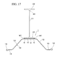
- FIG. 17 is a diagram illustrating a modification example of the combined steel sheet pile illustrated in FIG. 2 , and is a plan view illustrating the combined steel sheet pile in which a plate is disposed between the H-shaped steel and the steel sheet pile.
- FIG. 18A is an enlarged plan view illustrating the flange of the H-shaped steel and the web of the steel sheet pile of the combined steel sheet pile illustrated in FIG. 17 .
- FIG. 18B is an enlarged plan view illustrating the weld zone of the fillet weld of the combined steel sheet pile illustrated in FIG. 17 .
- FIG. 19A is an enlarged plan view illustrating fillet welds of the combined steel sheet pile in which a steel rod is disposed to come into contact with the web of the steel sheet pile and the end edge of the flange of the H-shaped steel.
- FIG. 19B is a diagram illustrating a state in which the weld zone of the fillet weld illustrated in FIG. 19A is cut off, and is a plan view illustrating the shape of the H-shaped steel after the cutting-off with the solid line and illustrating the shapes of the steel sheet pile and the steel rod with the two-dot chain line.
- FIG. 20 is a plan view illustrating a welding range and a grinding range in a case where joining by the fillet weld and grinding for reutilization are repeated.
- FIG. 21 is a plan view illustrating an example in which, after the steel sheet pile and the H-shaped steel are disassembled and the weld zone of the fillet weld is ground, the steel sheet pile and the H-shaped steel are joined again by the fillet welds with the steel rod interposed therebetween.
- FIG. 22 is a plan view illustrating an example in which, after the steel sheet pile and the H-shaped steel are disassembled and the weld zone of the fillet weld is ground, the steel sheet pile and the H-shaped steel are joined again by the fillet welds with a rectangular steel rod interposed therebetween.
- FIG. 23 is a plan view of a modification example of the combined steel sheet pile illustrated in FIG. 2 .
- FIG. 24 is an enlarged plan view illustrating the weld zone of the fillet weld of the combined steel sheet pile illustrated in FIG. 23 .
- FIG. 25 is a diagram illustrating an example in which the combined steel sheet pile is joined by the fillet welds which are intermittent in the longitudinal direction, and is a rear view illustrating an example in which the weld zones of the fillet welds and unweld zones are alternately arranged.
- FIG. 26 is a diagram illustrating an example in which the combined steel sheet pile is joined by the fillet welds which are intermittent in the longitudinal direction, and is a rear view illustrating an example in which the length of the unweld zone is twice the length of the weld zone.
- FIG. 27A is a schematic explanatory view illustrating an example of a method of constructing the diaphragm wall which uses the combined steel sheet pile.
- FIG. 27B is a schematic explanatory view illustrating an example of the method of constructing the diaphragm wall which uses the combined steel sheet pile.
- FIG. 27C is a schematic explanatory view illustrating an example of a method of pulling out the combined steel sheet pile from the diaphragm wall.
- FIG. 27D is a schematic explanatory view illustrating an example of a method of storing the combined steel sheet pile pulled out from the diaphragm wall.
- FIG. 27E is a schematic explanatory view illustrating an example of a method of reutilizing the combined steel sheet pile.
- FIG. 27F is a schematic explanatory view illustrating another example of the method of reutilizing the combined steel sheet pile.
- FIG. 28A is a side view illustrating a state where the combined steel sheet pile is pulled out of the diaphragm wall which uses the combined steel sheet pile according to an aspect of the present invention.
- FIG. 28B is a side view illustrating an example of cutting off the weld zone of the fillet weld of the combined steel sheet pile illustrated in FIG. 28A and disassembling the steel sheet pile and the H-shaped steel.
- FIG. 29A is a plan view of a combined steel sheet pile according to the related art.
- FIG. 29B is a plan view of the combined steel sheet pile according to the related art.
- FIG. 1A is a plan view illustrating the diaphragm wall which uses the combined steel sheet pile according to the first embodiment of the present invention.
- FIG. 1B is a partially cut away front view illustrating the diaphragm wall which uses the combined steel sheet pile according to the embodiment.
- FIG. 2 is an enlarged plan view of the combined steel sheet pile used in the diaphragm wall illustrated in FIG. 1A .
- FIG. 11 is an enlarged plan view illustrating a weld zone (weld metal) of a fillet weld which joins a steel sheet pile to an H-shaped steel.
- the combined steel sheet pile 1 includes the steel sheet pile 10 and the H-shaped steel 20 .
- the steel sheet pile 10 is, when viewed in plan view, that is, when viewed in a cross-section perpendicular to the longitudinal direction of the combined steel sheet pile 1 , configured as a hat-shaped steel sheet pile which includes a web 11 (steel sheet pile web) provided at the center portion in the sheet width direction, a pair of flanges 12 (steel sheet pile flanges) provided at both end portions of the web 11 to be tilted toward one surface side of the web 11 , arms 13 provided at the tip ends of the flanges 12 to be parallel to the web 11 , and joints 14 provided at the tip ends of the arms 13 .
- the pair of flanges 12 are provided to be tilted so as to become distant from each other as they become distant from the web 11 .
- the steel sheet pile 10 may also be configured as, as well as the hat-shaped steel sheet pile, when viewed in the cross-section, a U-shaped steel sheet pile which includes a web 11 (steel sheet pile web) provided at the center portion in the sheet width direction, a pair of flanges 12 (steel sheet pile flange) provided at both the end portions of the web 11 to be tilted toward the one surface side of the web 11 , and joints 14 provided at the tip ends of the flanges, and has a U-shape when viewed in the cross-section.
- the steel sheet pile 10 may also be configured as, when viewed in the cross-section, a linear steel sheet pile which includes a pair of joints 14 provided at both end portions of the steel sheet pile 10 and has a linear shape when viewed in the cross-section.
- the shape of the joint 14 is adjusted to be fitted to the joint 14 of another steel sheet pile 10 .
- the shape of the joint 14 is adjusted so that when the joint 14 is in a state of being fitted to the joint 14 of another steel sheet pile 10 , the joints 14 are not separated from each other.
- the steel sheet piles 10 adjacent to each other are connected by allowing the corresponding joints 14 to be fitted to each other.
- the steel sheet pile 10 of the first embodiment is a hot-rolled steel sheet pile molded by hot rolling.
- the steel sheet pile 10 has fitting grooves and locking claws molded so as not to be separated from each other when the joints 14 are in a state of being fitted to each other, and thus the strength of the joint 14 is increased.
- the steel sheet pile 10 may also be a cold-rolled steel sheet pile molded by cold-rolling.
- the H-shaped steel 20 includes, when viewed in the cross-section, a web 21 (H-shaped steel web) and a pair of flanges 22 (H-shaped steel flanges) provided at both end portions of the web 21 .
- the H-shaped steel 20 is joined by overlapping one flange 22 thereof and one surface of the web 11 (steel sheet pile web) of the steel sheet pile 10 .
- the H-shaped steel 20 is joined by overlapping the one flange 22 thereof and a surface on the opposite side to a concave portion 17 constituted by the web 11 and the pair of flanges 12 (steel sheet pile flanges) of the steel sheet pile 10 .
- the H-shaped steel 20 may be joined by overlapping the one flange 22 thereof and a surface on the side of the concave portion 17 constituted by the web 11 and the pair of flanges 12 (steel sheet pile flanges) of the steel sheet pile 10 .
- fillet welding is a method of welding two surfaces approximately orthogonal to each other, and is a welding in which a weld zone has a substantially triangular cross-section.
- the combined steel sheet pile 1 has a joining structure which can be assembled into the steel sheet pile 10 and the H-shaped steel 20 by cutting off weld zones 2 (weld metal) of the fillet welds W 1 by which the steel sheet pile 10 and the H-shaped steel 20 are joined, by grinding.
- weld zones 2 weld metal
- the weld zones 2 of the fillet welds W 1 by which the web 11 of the steel sheet pile 10 and the end edge 22 y of the flange 22 of the H-shaped steel 20 are joined, it is possible to disassemble the H-shaped steel 20 and the steel sheet pile 10 using a rotary cutting tool, fusing, a grinder, or the like.
- FIG. 12 is a diagram illustrating an example of cutting off the weld zone 2 of the fillet weld W 1 illustrated in FIG. 11 using the disassembling method according to an aspect of the present invention, and is a plan view illustrating the shape of the H-shaped steel 20 after the cutting-off with the solid line and illustrating the shape of the steel sheet pile 10 with the two-dot chain line.
- FIG. 28A is a side view illustrating a state where the combined steel sheet pile 1 is pulled out of the diaphragm wall which uses the combined steel sheet pile 1 according to an aspect of the present invention.
- FIG. 28B is a side view illustrating an example of cutting off the weld zone 2 of the fillet weld W 1 of the combined steel sheet pile 1 illustrated in FIG.
- the combined steel sheet pile 1 is pulled out and disassembled into the H-shaped steel 20 and the steel sheet pile 10 by efficiently cutting off the weld zone 2 of the fillet weld W 1 .
- the steel sheet pile 10 and the H-shaped steel 20 are not allowed to be bulky such that each of the members can be stored or transported.
- the combined steel sheet pile 1 becomes a combined steel sheet pile 1 which facilitates configuring of the steel sheet pile 10 and the H-shaped steel 20 to be assembled at a construction site of the diaphragm wall and disassembling thereof by cutting off the weld zone 2 of the fillet weld W 1 at the site. Accordingly, the combined steel sheet pile 1 facilitates assembling and disassembling in a manufacturing factory of the combined steel sheet pile.
- the one flange 22 (H-shaped steel flange) of the H-shaped steel 20 is disposed to overlap the surface of the web 11 on the opposite side to the concave portion 17 formed by the web 11 (steel sheet pile web) of the steel sheet pile 10 and the pair of flanges 12 (steel sheet pile flanges) so that the longitudinal direction of the H-shaped steel 20 and the longitudinal direction of the steel sheet pile 10 are parallel to each other.
- Both the end edges 22 y in the flange width direction Y of the one flange 22 of the H-shaped steel 20 have a leg length with a smaller dimension than that of the flange thickness of the flange 22 , and are joined to the web 11 of the steel sheet pile 10 by the fillet welds W 1 formed along the longitudinal direction.
- the combined steel sheet pile 1 as such has higher stiffness than that of a case where the steel sheet pile 10 is used alone.
- the combined steel sheet pile 1 is separated into the steel sheet pile 10 and the H-shaped steel 20 for storage by cutting off the weld zone 2 of the fillet weld W 1 , and is re-welded to be used as the combined steel sheet pile 1 .
- the weld zones 2 that are left in the steel sheet pile 10 and the H-shaped steel 20 have to be completely removed, and have to be ground until the base materials of the steel sheet pile 10 and the H-shaped steel 20 are exposed.
- the combined steel sheet pile 1 it is possible to reutilize the H-shaped steel 20 , which is less likely to wear, by replacing only the steel sheet pile 10 in which the joints 14 of the steel sheet pile 10 are likely to wear and a ratio of the weight of the steel is small. Therefore, a method of disassembling (method of cutting off) the combined steel sheet pile 1 which can reduce a grinding time as much as possible and in which the weld zone 2 (weld metal) is less likely to be left in the flange 22 (H-shaped steel flange) of the H-shaped steel is desirable.
- the above-mentioned fillet weld W 1 has a bead shape with equal length legs in design (in theory) as illustrated by the dotted line A of FIG. 11 .
- the fillet weld W 1 has a bead shape with unequal length legs, in which a long side 3 is on the web 11 side of the steel sheet pile 10 and a short side 5 is in the flange thickness direction X of the H-shaped steel 20 , due to its own weight of the melted metal (welded metal) during welding.
- a boundary portion 7 between the web 11 of the steel sheet pile 10 , the flange 22 of the H-shaped steel 20 , and the weld zone 2 in the penetration depth direction is positioned to be shifted in the flange width direction Y of the H-shaped steel 20 unlike in design.
- the boundary portion 7 is positioned on the surface of the web 11 of the steel sheet pile 10 when the combined steel sheet pile 1 is viewed in the cross-section perpendicular to the longitudinal direction.
- a surface along the longitudinal direction of the combined steel sheet pile 1 which includes a theoretical throat depth T, is defined as a throat depth surface F (illustrated by the one-dot chain line in FIG. 11 ).
- a surface which includes a line segment L (illustrated by the thick dotted line in FIG. 11 ) connecting a weld bead surface P positioned on the flange 22 side of the H-shaped steel 20 from the throat depth surface F and the boundary portion 7 and is formed along the longitudinal direction of the combined steel sheet pile 1 , is defined as a surface C (a substantially straight line or a curved line).
- the method of disassembling the combined steel sheet pile 1 which can reduce the grinding time to cut off and in which the weld zone 2 is less likely to be left in the flange 22 of the H-shaped steel 20 can be achieved.
- FIG. 13 is a diagram illustrating an example of cutting off the weld zone 2 of the fillet weld W 1 illustrated in FIG. 11 by a disassembling method according to the related art, and is a plan view illustrating the shape of the H-shaped steel 20 after the cutting-off with the solid line and illustrating the shape of the steel sheet pile 10 with the two-dot chain line.
- a cutting distance S 1 for cutting off the weld zone 2 (welded metal) of the fillet weld W 1 is longer than that of the case where the surface C is the cutting surface.
- FIG. 14 is a diagram illustrating an example of cutting off the weld zone 2 of the fillet weld W 1 illustrated in FIG. 11 by another disassembling method according to the related art, and is a plan view illustrating the shape of the H-shaped steel 20 after the cutting-off with the solid line and illustrating the shape of the steel sheet pile 10 with the two-dot chain line.
- FIG. 14 when viewed in the cross-section, in a case where a surface F 2 which does not intersect the throat depth surface F including the theoretical throat depth T but is on the web 11 side of the steel sheet pile 10 is the cutting surface, a joining region R of the weld zone 2 and the web 11 of the steel sheet pile 10 is left even after grinding. Therefore, there is a high concern of a form of cutting failure occurring.
- FIG. 12 is a diagram illustrating an example of cutting off the weld zone 2 of the fillet weld W 1 illustrated in FIG. 11 by the disassembling method according to the aspect of the present invention, and is a plan view illustrating the shape of the H-shaped steel 20 after the cutting-off with the solid line and illustrating the shape of the steel sheet pile 10 with the two-dot chain line. As illustrated in FIG.
- the surface C when viewed in the cross-section, in a case where the surface C which does not intersect the throat depth surface F including the theoretical throat depth T and is on the flange 22 side of the H-shaped steel 20 is the cutting surface, the surface C is cut off by grinding, for example, using a grinder, and thus a cutting length (cutting distance) for cutting off the weld zone 2 (welded metal) of the fillet weld W 1 can be shorten and a residual weld zone 6 (see FIG. 12 ) that is left in the flange 22 (H-shaped steel flange) of the H-shaped steel 20 can be reduced.
- the residual weld zone 6 can be reduced.
- the weld zone 2 welded metal positioned on the steel sheet pile 10 side than the throat depth surface F is left as a residual weld zone 9 on the steel sheet pile 10 side.
- the grinder or the like has a certain degree of thickness dimension, and thus, when viewed in a direction which perpendicularly intersects the longitudinal direction of the combined steel sheet pile 1 and is parallel to the surface C, even though the surface C is formed in a curved line other than in a straight line so as to be slightly wobbled (swollen), it is possible to cut off the cutting surface including the boundary portion 7 .
- the fillet weld W 1 may have a single bead shape which is continuous in the longitudinal direction of the combined steel sheet pile 1 , but may also be a plurality of fillet welds W 1 which are intermittent in the longitudinal direction.
- FIG. 25 is a diagram illustrating an example in which the combined steel sheet pile 1 is joined by the fillet welds W 1 which are intermittent in the longitudinal direction, and is a rear view illustrating an example in which the weld zones 2 of the fillet welds W 1 and unweld zones M are alternately arranged. As illustrated in FIG.
- the unweld zones M can be used as regions for welding, which is preferable. Therefore, the web 11 of the steel sheet pile 10 and the flange 22 of the H-shaped steel 20 can be easily joined and fixed by the fillet welds W 1 , which is preferable.
- a length M 1 of the unweld zone M in the longitudinal direction is preferably a multiple of a length N 1 of the weld zone 2 in the longitudinal direction.
- FIG. 25 illustrates a case where the length N 1 of the weld zone 2 and the length M 1 of the unweld zone M are the same length (one time).
- FIG. 26 is a diagram illustrating an example in which the combined steel sheet pile 1 joined by the fillet welds W 1 which are intermittent in the longitudinal direction, and is a rear view illustrating an example in which the weld zones 2 of the fillet welds W 1 and the unweld zones M are alternately arranged and the length M 1 of the unweld zone M in the longitudinal direction is twice the length N 1 of the weld zone 2 in the longitudinal direction.
- the unweld zones M can be used as the regions for welding, which is preferable. Therefore, after the cutting-off, grinding of the residual weld zone 6 on the H-shaped steel 20 side or the residual weld zone 9 on the steel sheet pile 10 side is unnecessary, resulting in a reduction in operation time.
- the number of times at which joining by the fillet weld W 1 can be performed can be increased without grinding of the residual weld zone 6 on the H-shaped steel 20 side and the residual weld zone 9 on the steel sheet pile 10 side.
- the length M 1 of the unweld zones M is the multiple of the length N 1 of the weld zone 2 and a ratio of the lengths of the unweld zones M and the weld zone 2 is maintained when the steel sheet pile 10 and the H-shaped steel 20 are reutilized and joined, the same weld ratio can be ensured in the combined steel sheet pile 1 before and after the disassembling and the re-assembling.
- welding can be performed on the unweld zone M at least one or more times over the same length N 1 as that of the weld zone 2 before the cutting-off. In this manner, the unweld zone M can be used without waste, which is efficient.
- the combined steel sheet pile 1 for which the disassembling method according to the embodiment is used be, when viewed in the cross-section, a hat-shaped steel sheet pile having a hat shape in which the steel sheet pile 10 includes the pair of steel sheet pile flanges 12 provided at both end portions of the web 11 , the arms 13 provided at the tip ends of the steel sheet pile flanges 12 , and the joints 14 provided at the tip end portions of the arms 13 , the fillet welds W 1 have the plurality of weld zones 2 and the unweld zones M in the longitudinal direction of the combined steel sheet pile 1 , the unweld zones M have a length which is a multiple of the length of the weld zone 2 , and the weld zones 2 and the unweld zones M are alternately arranged.
- FIG. 15 is an enlarged plan view illustrating the weld zone 2 of the fillet weld W 1 which joins the steel sheet pile 10 and H-shaped steel 20 with a gap G provided therebetween.
- the gap G of equal to or more than 0.2 mm and equal to or less than 5 mm is provided in advance between an end portion 22 x (end edge) in the flange thickness direction X of the flange 22 of the H-shaped steel 20 and the web 11 of the steel sheet pile 10 .
- the gap G is preferably equal to or more than 1 mm and equal to or less than 5 mm, and more preferably equal to or more than 2 mm and equal to or less than 5 mm.
- the weld zone 2 be cut off by the cutting method such as a grinder to allow a part of the weld zone 2 formed by the fillet weld W 1 on the side closer to the steel sheet pile 10 than the throat depth surface F to be left. Specifically, as illustrated in FIG.
- the weld zone 2 be cut off at the surface C 1 as the cutting surface, which does not intersect the throat depth surface F including the theoretical throat depth T when viewed in the cross-section and is on the flange 22 side of the H-shaped steel 20 .
- the surface C 1 is defined as a surface which includes a line segment L 1 connecting the weld bead surface P positioned on the flange 22 side of the H-shaped steel 20 than the throat depth surface F and a boundary portion 7 x and is formed along the longitudinal direction of the combined steel sheet pile 1 .
- the boundary portion 7 x is the boundary portion between the H-shaped steel 20 , the gap G, and the weld zone 2 .
- FIG. 16 is a diagram illustrating an example of cutting off the weld zone 2 of the fillet weld W 1 illustrated in FIG. 15 by the disassembling method according to the modification example, and is a plan view illustrating the shape of the H-shaped steel 20 after the cutting-off with the solid line and illustrating the shape of the steel sheet pile 10 with the two-dot chain line.
- the cutting length (cutting distance) for cutting off the weld zone 2 (welded metal) of the fillet weld W 1 can be shorten and the residual weld zone 6 which is left in the flange 22 (H-shaped steel flange) of the H-shaped steel 20 can be reduced.
- the combined steel sheet pile 1 can be cut off and disassembled without causing cutting scratches on the web 11 of the steel sheet pile 10 .
- a state where the end portion 22 x (end edge) of the flange 22 of the H-shaped steel 20 becomes distant from the web 11 of the steel sheet pile 10 is achieved. Therefore, a cutting distance in the case where the surface C 1 is cut off as the cutting surface is further reduced compared to a case where the gap G is not provided.
- the residual weld zone 6 can be reduced compared to a case where the gap G is not provided. Therefore, grinding of the residual weld zone 6 is unnecessary when the H-shaped steel 20 is reutilized after the cutting-off, and thus the operation time can be further reduced.
- a steel wedge (not illustrated) in the gap G between the flange 22 of the H-shaped steel 20 and the web 11 of the steel sheet pile 10 . Therefore, an operational load and an operation time during the grinding and separating operations using the grinder or the like can be reduced.
- the fillet weld W 1 may be ground by the grinder or the like so that a cutting surface is reliably shown on the H-shaped steel 20 side than the surface F including the theoretical throat depth T, and thereafter, by driving the steel wedge in the gap G, the H-shaped steel 20 and the steel 10 may be separated.
- the gap G is preferably equal to or more than 2 mm and equal to or less than 5 mm. Further, regarding the driving of the steel wedge for the separation, when the gap G is provided and the above-mentioned unweld zones M are further provided, the steel wedge is easily driven, which is preferable.
- FIG. 17 is a plan view illustrating the combined steel sheet pile 1 in which a plate 8 is disposed between the H-shaped steel 20 and the steel sheet pile 10 .
- FIG. 18A is an enlarged plan view illustrating the flange 22 of the H-shaped steel 20 and the web 11 of the steel sheet pile 10 of the combined steel sheet pile 1 illustrated in FIG. 17 .
- FIG. 18B is an enlarged plan view illustrating the weld zone 2 of the fillet weld W 1 of the combined steel sheet pile 1 illustrated in FIG. 17 .
- the plate 8 as illustrated in FIGS. 17, 18A, and 18B be disposed between the flange 22 of the H-shaped steel 20 and the web 11 of the steel sheet pile 10 .
- the plate width of the plate 8 has a smaller width dimension than the width dimension between the fillet welds W 1 , that is, is smaller than the flange width of the flange 22 of the H-shaped steel 20 .
- a rectangular steel plate, a bar-like steel plate, and a belt-like steel plate may be used as the plate 8 .
- the plate 8 may be appropriately fixed to the flange 22 of the H-shaped steel 20 or the web 11 of the steel sheet pile 10 by a spot welding or the like.
- the gap G is formed between the plate 8 and the fillet weld W 1 as illustrated in FIG. 18B .
- the gap G may be formed between the flange 22 of the H-shaped steel 20 and the web 11 of the steel sheet pile 10 .
- the plate 8 may also be fixed to the end portion of the H-shaped steel 20 or the steel sheet pile 10 in the longitudinal direction by a method such as a welding.
- the material of the plate 8 is preferably a metal material from the viewpoint of strength, and may be another material, for example, plastic or wood as long as the gap G can be formed.
- the plate thickness of the plate 8 preferably has a dimension of, for example, equal to or more than 0.2 mm and equal to or less than 5 mm.
- the plate thickness of the plate 8 is equal to or more than 0.2 mm because a thickness of equal to or more than 0.2 mm is advantageous to the manufacture of a steel plate and causes a reduction in cost.
- the plate thickness of the plate 8 is preferably equal to or more than 1 mm, and more preferably equal to or more than 2 mm.
- the plate thickness of the plate 8 when the plate thickness of the plate 8 is thicker than 5 mm, the gap G becomes too large, and thus there is a concern that the fillet welds W 1 may not be sufficiently formed. Accordingly, it is preferable that the plate thickness of the plate 8 be equal to or less than 5 mm and the gap G be equal to or less than 5 mm.
- FIG. 19A is an enlarged plan view illustrating a fillet weld W 2 and a fillet weld W 3 of the combined steel sheet pile 1 in which a steel rod 16 is disposed to come into contact with the web 11 of the steel sheet pile 10 and the end edge 22 y of the flange 22 of the H-shaped steel 20 .
- the steel rod 16 which comes into contact with the end edge 22 y of the flange 22 of the H-shaped steel 20 and the web 11 of the steel sheet pile 10 is disposed.
- the steel sheet pile 10 and the H-shaped steel 20 are joined together by the fillet weld W 2 joining the end edge 22 y and the steel rod 16 and the fillet weld W 3 joining the web 11 and the steel rod 16 . That is, by fixing the steel rod 16 to the web 11 of the steel sheet pile 10 with the fillet weld W 3 and by fixing the steel rod 16 to the flange 22 of the H-shaped steel 20 with the fillet weld W 2 , the combined steel sheet pile 1 in which the steel sheet pile 10 and the H-shaped steel 20 are integrated as one body is formed.
- the combined steel sheet pile 1 as such be cut off at a weld zone 2 x of the fillet weld W 2 by the grinder or the like to reduce the weld metal that is left in the H-shaped steel 20 .
- a weld zone 2 x of the fillet weld W 2 on the flange 22 side of the H-shaped steel 20 be cut off at a surface C 2 as the cutting surface.
- the surface C 2 is defined as a surface which includes a line segment L 2 connecting the weld bead surface P of the weld zone 2 x of the fillet weld W 2 and a boundary portion 7 y and is formed along the longitudinal direction of the combined steel sheet pile 1 .
- the boundary portion 7 y is the boundary portion between the H-shaped steel 20 , the steel rod 16 , and the weld zone 2 x.
- FIG. 19B is a diagram illustrating an example of cutting off the weld zone 2 x of the fillet weld W 2 illustrated in FIG. 19A by the disassembling method according to the modification example, and is a plan view illustrating the shape of the H-shaped steel 20 after the cutting-off with the solid line and illustrating the shapes of the steel sheet pile 10 and the steel rod 16 with the two-dot chain line.
- the cutting-off illustrated in FIG. 19B the cutting length (cutting distance) for cutting off the weld zone 2 x (weld metal) of the fillet weld W 2 can be shortened and the residual weld zone 6 which is left in the flange 22 (H-shaped steel flange) of the H-shaped steel 20 can be reduced.
- the cutting length (cutting distance) can be further reduced compared to any of the cases described above.
- the entire steel rod 16 or the substantially entire steel rod 16 is left in the web 11 of the steel sheet pile 10 with the fillet weld W 3 . That is, it is preferable that the weld zone 2 x of the combined steel sheet pile 1 be cut off so that a larger amount of the steel rod 16 is left on the web 11 side of the steel sheet pile 10 than that at the end edge 22 y of the H-shaped steel 20 .
- the residual weld zone 6 which is left in the end edge 22 y of the flange 20 of the H-shaped steel 20 can be preferably reduced, and thus grinding of the residual weld zone 6 is unnecessary when the H-shaped steel 20 is reutilized after the cutting-off, resulting in a further reduction in operation time.
- the steel sheet pile 10 and the H-shaped steel 20 are joined together by the fillet welds W 2 and the fillet welds W 3 with the steel rods 16 interposed therebetween, it is more preferable that joining be performed to further provide the unweld zones M.
- the shape of the steel rod 16 may also be square, rectangular, or triangular other than the circular shape illustrated in FIG. 19A when viewed in the cross-section perpendicular to the longitudinal direction.
- a modification example in which a rectangular steel plate is used as the steel rod 16 is illustrated in FIG. 22 .
- the combined steel sheet pile 1 illustrated in FIG. 22 has the same technical features except that the shape of the steel rod 16 is rectangular.
- the material of the steel rod 16 is preferably steel from the viewpoint of weldability, and may be also another material such as pure iron, stainless steel, copper, or nickel as long as the welding of difference types of materials to the steel sheet pile 10 and the H-shaped steel 20 is possible.
- the steel rod 16 may be fixed to a part or the entirety of the combined steel sheet pile 1 in the longitudinal direction by the fillet welds W 2 and the fillet welds W 3 which are continuous or intermittent.
- FIG. 20 is a plan view illustrating a welding range and a grinding range in a case where joining by the fillet weld W 1 and grinding for reutilization are repeated.
- the welding range and the grinding range on the flange 22 side of the H-shaped steel 20 gradually widen to a fillet weld W 1 illustrated by the sold line, a fillet weld W 1 illustrated by the dotted line, and a fillet weld W 1 illustrated by the two-dot chain line. Therefore, the amount of welds is increased for reutilization, resulting in the degradation in economic efficiency.
- FIG. 21 is a plan view illustrating an example in which, after the steel sheet pile 10 and the H-shaped steel 20 are disassembled and the weld zone 2 of the fillet weld W 1 is ground, the steel sheet pile 10 and the H-shaped steel 20 are joined again by the fillet weld W 2 and the fillet weld W 3 with the steel rod 16 interposed therebetween. As illustrated in FIG. 21 , the steel sheet pile 10 and the H-shaped steel 20 are joined together by the fillet weld W 2 and the fillet weld W 3 with the steel rod 16 interposed therebetween so as to be reutilized, and thus the welding range can be reduced, which is preferable.
- FIG. 21 illustrates an example in which, in a case where the combined steel sheet pile 1 is assembled by joining the steel sheet pile 10 and the H-shaped steel 20 , joining is performed as a first joining by the fillet weld W 1 without the steel rod 16 interposed therebetween, the weld zone 2 of the fillet weld W 1 is cut off, the residual weld zone 6 which is left in the H-shaped steel 20 after the cutting-off is removed, and joining is performed again by the fillet weld W 2 and the fillet weld W 3 with the steel rod 16 interposed therebetween.
- the weld zone 2 x of the fillet weld W 2 on the flange 22 side of the H-shaped steel 20 may be cut off at the surface C 2 as the cutting surface.
- the flange 22 of the H-shaped steel 20 may have tilted end edges 22 y 1 .
- the tilted end edges 22 y 1 illustrated in FIGS. 23 and 24 are provided, the amount of the steel rod 16 protruding is reduced. Therefore, operation safety is enhanced when the combined steel sheet pile 1 is assembled or disassembled and when the diaphragm wall is constructed using the combined steel sheet pile 1 .
- the section modulus about the axis of the direction Y in which the center of the combined steel sheet pile 1 illustrated in FIG. 2 passes through is preferably, for example, 3,500 cm 3 /m to 14,000 cm 3 /m.
- the section modulus of the combined steel sheet pile 1 per 1 m of the wall width is preferably 3,500 cm 3 /m to 14,000 cm 3 /m.
- the section modulus is an integer obtained by dividing the second moment of area of the cross-section by the distances from the center axis to the end portions in the longitudinal direction and is determined by the shape of the cross-section and the position of the center axis.
- the second moment of the cross-section is defined as the sum of the products of a differential area element of the cross-section and the square of a distance from the center axis to the element.
- the adjacent joints 14 of the combined steel sheet piles 1 are fitted to one another and are inserted into the ground.
- the ground between the diaphragm walls 15 which oppose each other is excavated, and a strut 18 is installed therein, thereby constructing an underground structure 4 .
- the space between the underground structure 4 and the diaphragm wall 15 is backfilled with excavated soil and the like, and the strut 18 is removed.
- FIG. 27A after the diaphragm walls 15 are constructed, the ground between the diaphragm walls 15 which oppose each other is excavated, and a strut 18 is installed therein, thereby constructing an underground structure 4 .
- the space between the underground structure 4 and the diaphragm wall 15 is backfilled with excavated soil and the like, and the strut 18 is removed.
- the combined steel sheet piles 1 including the steel sheet pile 10 and the H-shaped steel 20 are pulled out by a construction machine.
- the pulled combined steel sheet pile 1 is installed so that the steel sheet pile 10 is positioned on the lower side on the ground.
- the weld zone 2 of the fillet weld W 1 is cut off and separated by the disassembling method described above.
- FIG. 27D about five layers of the steel sheet piles 10 arranged in parallel are stacked and the steel sheet piles 10 are further stacked thereon appropriately with spacers such as battens therebetween in a plurality of stages for storage.
- the H-shaped steels 20 are arranged in parallel and the steel sheet piles 10 are further stacked thereon appropriately with the spacers such as battens therebetween in a plurality of stages for storage.
- the worn steel sheet pile 10 is replaced with a new steel sheet pile 10 .
- the new steel sheet pile 10 is joined to have the same structure as the joining structure by the fillet welds before the replacement or have a joining structure in which the positions of the fillet welds are shifted in the longitudinal direction, thereby assembling a new combined steel sheet pile 1 .
- the H-shaped steel 20 may be replaced with an H-shaped steel 20 having a larger beam height (girder height), in other words, an H-shaped steel 20 in which the dimension of the web 21 (H-shaped steel web) is large.
- the combined steel sheet pile 1 can be installed in a deeper place, at the construction site of the diaphragm wall 15 .
- FIG. 3A is a plan view illustrating the diaphragm wall 15 which uses the combined steel sheet pile 1 according to the second embodiment of the present invention.
- FIG. 3B is a partially cut away front view of the diaphragm wall 15 which uses the combined steel sheet pile 1 according to the embodiment.
- FIG. 4 is an enlarged plan view of the combined steel sheet pile 1 used in the diaphragm wall 15 illustrated in FIG. 3A .
- the combined steel sheet pile 1 of this embodiment includes the steel sheet pile 10 which is the hat-shaped steel sheet pile as in the first embodiment.
- this embodiment is different from the first embodiment in that the one flange 22 (H-shaped steel flange) of the H-shaped steel 20 overlaps and is joined to the surface of the concave portion 17 constituted by the web 11 and the pair of flanges 12 (steel sheet pile flanges) of the steel sheet pile 10 .
- bending stiffness about the axis of the direction Y in which the center of gravity in the direction Y in FIG. 4 passes through is reduced.
- the other features are the same as those of the first embodiment.
- the combined steel sheet pile 1 of this embodiment uses the same steel sheet pile 10 and H-shaped steel 20 as those of the first embodiment, and has the same cross-sectional area when viewed in the cross-section perpendicular to the longitudinal direction.
- the combined steel sheet pile 1 of this embodiment is shorter in length in the direction X compared to the first embodiment. Therefore, the stiffness of the combined steel sheet pile 1 of this embodiment is reduced than that of the case of first embodiment.
- the diaphragm wall 15 is constructed by using the combined steel sheet pile 1 of this embodiment, the diaphragm wall 15 can be installed near the site boundary. Therefore, in a case where the site for installing the diaphragm wall 15 is narrow, the site can be efficiently used.
- the other features for example, the method of constructing the diaphragm wall 15 using the combined steel sheet pile 1 and the method of pulling out the combined steel sheet pile 1 from the diaphragm wall 15 and disassembling the combined steel sheet pile 1 into the steel sheet pile 10 and the H-shaped steel 20 , are the same as those of the first embodiment.
- each of the modification examples of the first embodiment can be applied.
- the gap G may be formed between the flange 22 of the H-shaped steel 20 and the web 11 of the steel sheet pile 10 .
- the gap G may be formed by the plate 8 between the flange 22 of the H-shaped steel 20 and the web 11 of the steel sheet pile 10 .
- joining by the fillet weld W 1 illustrated in FIG. 15 may be performed, and the disassembling method illustrated in FIG. 16 may be employed.
- the steel rod 16 may be disposed to come into contact with the web 11 of the steel sheet pile 10 and the end edge 22 y of the flange 22 of the H-shaped steel 20 .
- joining by the fillet weld W 2 and the fillet weld W 3 illustrated in FIG. 19A may be performed, and the disassembling method illustrated in FIG. 19B may be employed.
- joining may be performed by the fillet weld W 2 and the fillet weld W 3 with the steel rod 16 interposed therebetween.
- FIG. 5 is a plan view illustrating the diaphragm wall 15 which uses the combined steel sheet pile 1 according to a third embodiment of the present invention.
- FIG. 6 is an enlarged plan view of the combined steel sheet pile 1 used in the diaphragm wall 15 illustrated in FIG. 5 .
- the combined steel sheet pile 1 of this embodiment includes the steel sheet pile 10 having a U shape when viewed in the cross-section perpendicular to the longitudinal direction.
- the steel sheet pile 10 is configured as the U-shaped steel sheet pile which includes, when viewed in the cross-section, the web 11 (steel sheet pile web) provided at the center portion in the sheet width direction, the pair of flanges 12 (steel sheet pile flanges) provided to be tilted from both end portions of the web 11 toward one surface side of the web 11 , and the joints 14 provided at the tip ends of the flanges 12 .
- the U-shaped steel sheet pile which is widely used as a permanent structure or for temporary earth-retaining installation can be used as the steel sheet pile 10 .
- the steel sheet pile 10 which is the U-shaped steel sheet pile that is widely used with the H-shaped steel 20 the combined steel sheet pile 1 having high versatility and higher stiffness can be achieved.
- each of the modification examples of the first embodiment can be applied.
- the gap G may be formed between the flange 22 of the H-shaped steel 20 and the web 11 of the steel sheet pile 10 .
- the gap G may be formed by the plate 8 between the flange 22 of the H-shaped steel 20 and the web 11 of the steel sheet pile 10 .
- the steel rod 16 may be disposed and joined to come into contact with the web 11 of the steel sheet pile 10 and the end edge 22 y of the flange 22 of the H-shaped steel 20 .
- the method of constructing the diaphragm wall 15 using the combined steel sheet pile 1 the method of pulling out the combined steel sheet pile 1 from the diaphragm wall 15 and disassembling the combined steel sheet pile 1 into the steel sheet pile 10 and the H-shaped steel 20 , and the like are the same as those of the first embodiment.
- FIG. 7 is a plan view illustrating the diaphragm wall 15 which uses the combined steel sheet pile 1 according to a fourth embodiment of the present invention.
- FIG. 8 is an enlarged plan view of the combined steel sheet pile 1 used in the diaphragm wall 15 illustrated in FIG. 7 .
- the combined steel sheet pile 1 of this embodiment includes a steel sheet pile 10 which is a cold-rolled steel sheet pile molded by cold rolling.
- the steel sheet pile 10 may not be formed in a complex shape unlike a hot-rolled steel sheet pile which is molded by hot rolling and thus has high shape imparting properties as in the first embodiment.
- the cold-rolled steel sheet pile which is manufactured at low cost and high versatility due to cold rolling performed with high productivity can be used as the steel sheet pile 10 .
- each of the modification examples of the first embodiment can be applied.
- the method of constructing the diaphragm wall 15 using the combined steel sheet pile 1 the method of pulling out the combined steel sheet pile 1 from the diaphragm wall 15 and disassembling the combined steel sheet pile 1 into the steel sheet pile 10 and the H-shaped steel 20 , and the like are the same as those of the first embodiment.
- FIG. 9 is a plan view illustrating the diaphragm wall 15 which uses the combined steel sheet pile 1 according to a fifth embodiment of the present invention.
- FIG. 10 is an enlarged plan view of the combined steel sheet pile 1 used in the diaphragm wall 15 illustrated in FIG. 9 .
- the steel sheet pile 10 is configured as a hat-shaped steel sheet pile which includes two Z-shaped steel sheet piles 10 x and has a hat shape when viewed in the cross-section perpendicular to the longitudinal direction by fitting a joint 14 x of one Z-shaped steel sheet pile 10 x to a joint 14 y of the another Z-shaped steel sheet pile 10 x .
- the joint 14 x and the joint 14 y at both end portions in the sheet width direction do not have the same shape when viewed in the cross-section.
- the joint 14 x and the joint 14 y are fitted to each other by reversing the another Z-shaped steel sheet pile 10 x to the one Z-shaped steel sheet pile 10 x , thereby forming the steel sheet pile 10 having the hat shape.
- each of the modification examples of the first embodiment can be applied.
- the method of constructing the diaphragm wall 15 using the combined steel sheet pile 1 the method of pulling out the combined steel sheet pile 1 from the diaphragm wall 15 and disassembling the combined steel sheet pile 1 into the steel sheet pile 10 and the H-shaped steel 20 , and the like are the same as those of the case of the first embodiment.
- the one flange 22 (H-shaped steel flange) of the H-shaped steel 20 may overlap and be joined to the surface of the concave portion 17 constituted of the steel sheet pile 10 of this embodiment.
- the steel sheet pile 10 and the H-shaped steel 20 can be joined together by the fillet weld W 1 .
- the H-shaped steels 20 having different sizes can be combined with the steel sheet piles 10 . Accordingly, in a case where different section stiffness is needed, a new combined steel sheet pile 1 can be easily formed, and thus acceptable wall body specifications can be achieved.
- the weld zone 2 of the fillet weld W 1 has a leg length with a smaller dimension than the flange thickness of the H-shaped steel 20 , and thus removal by fusing or removal by grinding using an electrical grinding tool such as a grinder is facilitated.
- a combined steel sheet pile 1 which uses a steel sheet pile other than the steel sheet pile 10 and for example, an I-shaped steel other than the H-shaped steel 20 may also be utilized.
- a combined steel sheet pile which can be constructed as one body during installation, and after being pulled out, can be easily disassembled by cutting off a weld zone of fillet welding which joins a steel sheet pile to an H-shaped steel, a diaphragm wall thereof, and a method of disassembling the combined steel sheet pile can be provided, and thus high industrial applicability is achieved.
Landscapes
- Engineering & Computer Science (AREA)
- Life Sciences & Earth Sciences (AREA)
- Structural Engineering (AREA)
- Civil Engineering (AREA)
- Mining & Mineral Resources (AREA)
- Paleontology (AREA)
- General Life Sciences & Earth Sciences (AREA)
- General Engineering & Computer Science (AREA)
- Environmental & Geological Engineering (AREA)
- Hydrology & Water Resources (AREA)
- Physics & Mathematics (AREA)
- Optics & Photonics (AREA)
- Mechanical Engineering (AREA)
- Bulkheads Adapted To Foundation Construction (AREA)
Abstract
Description
- [Patent Document 1] Japanese Unexamined Patent Application, First Publication No. H11-140864
- [Patent Document 2] Japanese Unexamined Patent Application, First Publication No. 2002-212943
- [Patent Document 3] Japanese Unexamined Patent Application, First Publication No. 2005-299202
- [Patent Document 4] Japanese Unexamined Patent Application, First Publication No. 2008-38490
-
- 1: COMBINED STEEL SHEET PILE
- 2: WELD ZONE 2 (WELDED METAL)
- 3: LONG SIDE
- 4: UNDERGROUND STRUCTURE
- 5: SHORT SIDE
- 6: RESIDUAL WELD ZONE (RESIDUAL WELD ZONE OF H-SHAPED STEEL FLANGE)
- 7, 7 x, 7 y: BOUNDARY PORTION
- 8: PLATE
- 9: RESIDUAL WELD ZONE (RESIDUAL WELD ZONE OF STEEL SHEET PILE WEB)
- 10: STEEL SHEET PILE
- 11: WEB (STEEL SHEET PILE WEB)
- 12: FLANGE (STEEL SHEET PILE FLANGE)
- 13: ARM
- 14: JOINT
- 15: DIAPHRAGM WALL
- 16: STEEL ROD
- 17: CONCAVE PORTION
- 18: STRUT
- 20: H-SHAPED STEEL
- 21: WEB (H-SHAPED STEEL WEB)
- 22: FLANGE (H-SHAPED STEEL FLANGE)
- 22 y: END EDGE (END EDGE OF H-SHAPED STEEL FLANGE)
- G: GAP
- M: UNWELD ZONE
- W1, W2, W3: FILLET WELD
Claims (4)
Applications Claiming Priority (3)
| Application Number | Priority Date | Filing Date | Title |
|---|---|---|---|
| JP2011155708 | 2011-07-14 | ||
| JP2011-155708 | 2011-07-14 | ||
| PCT/JP2012/067935 WO2013008915A1 (en) | 2011-07-14 | 2012-07-13 | Composite steel sheet pile, underground continuous wall, and decomposition method of composite steel sheet pile |
Publications (2)
| Publication Number | Publication Date |
|---|---|
| US20140138427A1 US20140138427A1 (en) | 2014-05-22 |
| US9512590B2 true US9512590B2 (en) | 2016-12-06 |
Family
ID=47506190
Family Applications (1)
| Application Number | Title | Priority Date | Filing Date |
|---|---|---|---|
| US14/131,378 Expired - Fee Related US9512590B2 (en) | 2011-07-14 | 2012-07-13 | Combined steel sheet pile, diaphragm wall, and method of disassembling combined steel sheet pile |
Country Status (4)
| Country | Link |
|---|---|
| US (1) | US9512590B2 (en) |
| JP (1) | JP5500317B2 (en) |
| TW (1) | TWI534323B (en) |
| WO (1) | WO2013008915A1 (en) |
Cited By (1)
| Publication number | Priority date | Publication date | Assignee | Title |
|---|---|---|---|---|
| RU204730U1 (en) * | 2021-02-09 | 2021-06-08 | Общество с ограниченной ответственностью "СТРОИТЕЛЬНАЯ КОМПАНИЯ "ЛИДЕР" | PANEL SHUTTLE |
Families Citing this family (22)
| Publication number | Priority date | Publication date | Assignee | Title |
|---|---|---|---|---|
| US10494783B2 (en) * | 2015-10-13 | 2019-12-03 | Armour Wall Group Pty Ltd | Earth retention levee system |
| CN105780790B (en) * | 2016-03-24 | 2017-10-03 | 浙江大学城市学院 | The nearly poor combined steel sheet-pile cofferdam subaqueous bearing platform construction method of dike high water level |
| CN108301397B (en) * | 2018-01-31 | 2023-12-15 | 山东建筑大学 | A multi-wing sheet pile structure and construction method suitable for soft soil foundations |
| CN108729450A (en) * | 2018-05-30 | 2018-11-02 | 中水电第十工程局(郑州)有限公司 | A kind of pipeline engineering steel sheet pile method for protecting support |
| CN108978634A (en) * | 2018-06-28 | 2018-12-11 | 中交上海航道局有限公司 | A kind of steel sheet pile inserting piling auxiliary force application structure |
| US10995467B2 (en) * | 2018-10-19 | 2021-05-04 | J.D. Fields & Company, Inc. | Combined wall piling system |
| CN109653233B (en) * | 2018-11-14 | 2021-05-25 | 中交一公局桥隧工程有限公司 | Construction method of recyclable bottom plate for large-volume bearing platform and single-wall steel sleeve box |
| CN112647489A (en) * | 2019-10-13 | 2021-04-13 | 上海城地建设工程有限公司 | All-steel enclosure structure with locking device |
| CN112609705A (en) * | 2020-12-09 | 2021-04-06 | 中国化学工程第六建设有限公司 | Steel sheet pile supporting system and method suitable for shallow soft soil foundation pit |
| CN113356246A (en) * | 2021-05-15 | 2021-09-07 | 中铁九局集团第六工程有限公司 | Construction method of combined cofferdam under hard riverbed |
| CN113275784B (en) * | 2021-05-31 | 2023-03-24 | 湘潭大学 | Welding device for welding combined steel sheet piles |
| US12480272B2 (en) * | 2022-02-18 | 2025-11-25 | American Transmission Company LLC | Electrical pole with H-web caisson |
| USD1078462S1 (en) * | 2022-09-27 | 2025-06-10 | Sergey Aleksandrovich Voloskov | Locking connector for sheet piles |
| USD1054844S1 (en) * | 2023-02-06 | 2024-12-24 | Richard Heindl | Sheet pile |
| CA223293S (en) * | 2023-02-06 | 2024-09-24 | Heindl Richard | Sheet pile |
| CA223291S (en) * | 2023-02-06 | 2025-04-07 | Heindl Richard | Sheet pile corner |
| CA223292S (en) * | 2023-02-06 | 2025-04-07 | Heindl Richard | Sheet pile corner |
| CN116696358A (en) * | 2023-07-12 | 2023-09-05 | 中水北方勘测设计研究有限责任公司 | Quick supporting and retaining structure for shaft collapse |
| WO2025182130A1 (en) * | 2024-02-27 | 2025-09-04 | 日本製鉄株式会社 | Construction assistance device for steel sheet piling, construction assistance method for steel sheet piling, wall construction method, management method for steel sheet piling, wall, steel sheet piling, recording medium, and program |
| JP7723338B1 (en) * | 2024-02-27 | 2025-08-14 | 日本製鉄株式会社 | Steel sheet pile construction support device, steel sheet pile construction support method, wall construction method, steel sheet pile management method, wall, steel sheet pile, recording medium and program |
| JP1788671S (en) | 2024-04-02 | 2025-01-09 | Sheet pile connector | |
| KR102927388B1 (en) | 2025-11-19 | 2026-02-19 | 주식회사 대동엠에스 | Truss structure of lightweight and long span |
Citations (11)
| Publication number | Priority date | Publication date | Assignee | Title |
|---|---|---|---|---|
| JPS6198817A (en) | 1984-10-19 | 1986-05-17 | Asuku Kenkyusho:Kk | Method of forming concrete wall of underground structure employing composite sheet pile and composite sheet pile as weir panel |
| JPH11140864A (en) | 1997-11-05 | 1999-05-25 | Kawasaki Steel Corp | Wall-type steel sheet pile, its manufacturing method and its joining method |
| JP2002212943A (en) | 2001-01-19 | 2002-07-31 | Sumitomo Metal Ind Ltd | Underground diaphragm wall steel and diaphragm wall |
| US20040093821A1 (en) * | 2002-11-15 | 2004-05-20 | Shinji Taenak | Metal sheet pile |
| US20040101370A1 (en) * | 2002-11-15 | 2004-05-27 | Kenji Nishiumi | Metal sheet pile |
| JP2005299202A (en) | 2004-04-12 | 2005-10-27 | Nippon Steel Corp | Steel sheet pile, retaining structure using the sheet pile, and construction method of retaining structure |
| US20060110220A1 (en) * | 2004-11-19 | 2006-05-25 | Edward Cable | Irregularly surfaced h pile |
| JP2008038490A (en) | 2006-08-07 | 2008-02-21 | Nippon Steel Corp | Processed sheet pile for underground continuous wall and manufacturing method thereof |
| JP2008267069A (en) | 2007-04-24 | 2008-11-06 | Nippon Steel Corp | Steel material for underground continuous wall, underground continuous wall, and method for constructing underground continuous wall |
| US20100151269A1 (en) * | 2006-01-17 | 2010-06-17 | Arcelormittal Commercial Rps S.A.R.L. | Sheet pile in double-t form |
| TW201116670A (en) | 2009-04-21 | 2011-05-16 | Sumitomo Metal Ind | Composite steel sheet pile and steel sheet pile wall using the composite steel sheet pile |
-
2012
- 2012-07-13 US US14/131,378 patent/US9512590B2/en not_active Expired - Fee Related
- 2012-07-13 TW TW101125307A patent/TWI534323B/en not_active IP Right Cessation
- 2012-07-13 WO PCT/JP2012/067935 patent/WO2013008915A1/en not_active Ceased
- 2012-07-13 JP JP2013524001A patent/JP5500317B2/en not_active Expired - Fee Related
Patent Citations (11)
| Publication number | Priority date | Publication date | Assignee | Title |
|---|---|---|---|---|
| JPS6198817A (en) | 1984-10-19 | 1986-05-17 | Asuku Kenkyusho:Kk | Method of forming concrete wall of underground structure employing composite sheet pile and composite sheet pile as weir panel |
| JPH11140864A (en) | 1997-11-05 | 1999-05-25 | Kawasaki Steel Corp | Wall-type steel sheet pile, its manufacturing method and its joining method |
| JP2002212943A (en) | 2001-01-19 | 2002-07-31 | Sumitomo Metal Ind Ltd | Underground diaphragm wall steel and diaphragm wall |
| US20040093821A1 (en) * | 2002-11-15 | 2004-05-20 | Shinji Taenak | Metal sheet pile |
| US20040101370A1 (en) * | 2002-11-15 | 2004-05-27 | Kenji Nishiumi | Metal sheet pile |
| JP2005299202A (en) | 2004-04-12 | 2005-10-27 | Nippon Steel Corp | Steel sheet pile, retaining structure using the sheet pile, and construction method of retaining structure |
| US20060110220A1 (en) * | 2004-11-19 | 2006-05-25 | Edward Cable | Irregularly surfaced h pile |
| US20100151269A1 (en) * | 2006-01-17 | 2010-06-17 | Arcelormittal Commercial Rps S.A.R.L. | Sheet pile in double-t form |
| JP2008038490A (en) | 2006-08-07 | 2008-02-21 | Nippon Steel Corp | Processed sheet pile for underground continuous wall and manufacturing method thereof |
| JP2008267069A (en) | 2007-04-24 | 2008-11-06 | Nippon Steel Corp | Steel material for underground continuous wall, underground continuous wall, and method for constructing underground continuous wall |
| TW201116670A (en) | 2009-04-21 | 2011-05-16 | Sumitomo Metal Ind | Composite steel sheet pile and steel sheet pile wall using the composite steel sheet pile |
Non-Patent Citations (4)
| Title |
|---|
| International Search Report, mailed Oct. 9, 2012, issued in PCT/JP2012/067935. |
| JP2008-267069 computer english translation Jun. 11, 2015. * |
| Taiwanese Office Action dated May 13, 2015, issued in Taiwanese Patent Application No. 101125307. |
| Written Opinion of the International Searching Authority, mailed Oct. 9, 2012, issued in PCT/JP2012/067935. |
Cited By (1)
| Publication number | Priority date | Publication date | Assignee | Title |
|---|---|---|---|---|
| RU204730U1 (en) * | 2021-02-09 | 2021-06-08 | Общество с ограниченной ответственностью "СТРОИТЕЛЬНАЯ КОМПАНИЯ "ЛИДЕР" | PANEL SHUTTLE |
Also Published As
| Publication number | Publication date |
|---|---|
| TW201313991A (en) | 2013-04-01 |
| TWI534323B (en) | 2016-05-21 |
| JPWO2013008915A1 (en) | 2015-02-23 |
| WO2013008915A1 (en) | 2013-01-17 |
| JP5500317B2 (en) | 2014-05-21 |
| US20140138427A1 (en) | 2014-05-22 |
Similar Documents
| Publication | Publication Date | Title |
|---|---|---|
| US9512590B2 (en) | Combined steel sheet pile, diaphragm wall, and method of disassembling combined steel sheet pile | |
| JP4943218B2 (en) | Steel material for underground continuous wall, underground continuous wall, and method for constructing underground continuous wall | |
| JP2005299202A (en) | Steel sheet pile, retaining structure using the sheet pile, and construction method of retaining structure | |
| CN102472031B (en) | Continuous steel wall and method for constructing same | |
| JP5413541B2 (en) | Combination steel sheet pile, underground continuous wall, and reuse method of combination steel sheet pile | |
| KR101769255B1 (en) | Steel Pipe Assembly for Roof Structure | |
| JP2017089130A (en) | Yamadome support structure and its construction method | |
| JP6253630B2 (en) | Synthetic segments, rings and subsidence structures | |
| KR101255515B1 (en) | The tunel execution method | |
| JP7229667B2 (en) | How to build the foundation structure | |
| WO2016001997A1 (en) | Bridge construction method and bridge structure | |
| JP2017180048A (en) | Steel sheet pile wall | |
| JP7543170B2 (en) | Steel earth retaining panel and earth retaining structure using said steel earth retaining panel | |
| JP6893799B2 (en) | Beam flint connection structure and beam flint connection piece | |
| JP2013019245A (en) | Combination steel sheet pile, underground continuous wall, and method of removing combination steel sheet pile | |
| JP5871624B2 (en) | Construction method of retaining wall | |
| JP2017180046A (en) | Reinforcement structure and reinforcement method for existing steel pile wall | |
| JP7219529B2 (en) | Combination structure of steel materials, shoring structure and construction method | |
| JP6905813B2 (en) | Synthetic segment and ring | |
| JP2018127796A (en) | Switching metal fitting of cut beam member | |
| KR102746164B1 (en) | R.W(Recycling Wale) and strut wale connection assembly | |
| JP5037997B2 (en) | Leading beam construction method and leading beam connection structure | |
| KR102130612B1 (en) | Precast concrete segments using the framing unit set | |
| KR101688744B1 (en) | Method for Fabrication of Steel pipe roof | |
| KR20170090190A (en) | Steel structures having departure prevention structure for sheathing work and construction method thereof |
Legal Events
| Date | Code | Title | Description |
|---|---|---|---|
| AS | Assignment |
Owner name: NIPPON STEEL & SUMITOMO METAL CORPORATION, JAPAN Free format text: ASSIGNMENT OF ASSIGNORS INTEREST;ASSIGNORS:NAGATSU, RYOSUKE;TERASAKI, SHIGEKI;TESHIMA, KEI;AND OTHERS;REEL/FRAME:031918/0056 Effective date: 20131225 |
|
| STCF | Information on status: patent grant |
Free format text: PATENTED CASE |
|
| AS | Assignment |
Owner name: NIPPON STEEL CORPORATION, JAPAN Free format text: CHANGE OF NAME;ASSIGNOR:NIPPON STEEL & SUMITOMO METAL CORPORATION;REEL/FRAME:049257/0828 Effective date: 20190401 |
|
| MAFP | Maintenance fee payment |
Free format text: PAYMENT OF MAINTENANCE FEE, 4TH YEAR, LARGE ENTITY (ORIGINAL EVENT CODE: M1551); ENTITY STATUS OF PATENT OWNER: LARGE ENTITY Year of fee payment: 4 |
|
| FEPP | Fee payment procedure |
Free format text: MAINTENANCE FEE REMINDER MAILED (ORIGINAL EVENT CODE: REM.); ENTITY STATUS OF PATENT OWNER: LARGE ENTITY |
|
| LAPS | Lapse for failure to pay maintenance fees |
Free format text: PATENT EXPIRED FOR FAILURE TO PAY MAINTENANCE FEES (ORIGINAL EVENT CODE: EXP.); ENTITY STATUS OF PATENT OWNER: LARGE ENTITY |
|
| STCH | Information on status: patent discontinuation |
Free format text: PATENT EXPIRED DUE TO NONPAYMENT OF MAINTENANCE FEES UNDER 37 CFR 1.362 |
|
| FP | Lapsed due to failure to pay maintenance fee |
Effective date: 20241206 |