US9509873B2 - Image forming apparatus with communication device - Google Patents

Image forming apparatus with communication device Download PDF

Info

Publication number
US9509873B2
US9509873B2 US13/852,795 US201313852795A US9509873B2 US 9509873 B2 US9509873 B2 US 9509873B2 US 201313852795 A US201313852795 A US 201313852795A US 9509873 B2 US9509873 B2 US 9509873B2
Authority
US
United States
Prior art keywords
image forming
unit
communication
forming apparatus
housing
Prior art date
Legal status (The legal status is an assumption and is not a legal conclusion. Google has not performed a legal analysis and makes no representation as to the accuracy of the status listed.)
Active
Application number
US13/852,795
Other versions
US20130286433A1 (en
Inventor
Ryoichi Matsushima
Hirofumi Kondo
Yasuhiro Kato
Masayoshi Hayashi
Masato Sueyasu
Reiko Toyama
Current Assignee (The listed assignees may be inaccurate. Google has not performed a legal analysis and makes no representation or warranty as to the accuracy of the list.)
Brother Industries Ltd
Original Assignee
Brother Industries Ltd
Priority date (The priority date is an assumption and is not a legal conclusion. Google has not performed a legal analysis and makes no representation as to the accuracy of the date listed.)
Filing date
Publication date
Priority claimed from JP2012100080A external-priority patent/JP6064361B2/en
Priority claimed from JP2012139682A external-priority patent/JP2014004687A/en
Application filed by Brother Industries Ltd filed Critical Brother Industries Ltd
Assigned to BROTHER KOGYO KABUSHIKI KAISHA reassignment BROTHER KOGYO KABUSHIKI KAISHA ASSIGNMENT OF ASSIGNORS INTEREST (SEE DOCUMENT FOR DETAILS). Assignors: Toyama, Reiko, HAYASHI, MASAYOSHI, KATO, YASUHIRO, KONDO, HIROFUMI, SUEYASU, MASATO, MATSUSHIMA, RYOICHI
Publication of US20130286433A1 publication Critical patent/US20130286433A1/en
Priority to US15/349,049 priority Critical patent/US9900453B2/en
Application granted granted Critical
Publication of US9509873B2 publication Critical patent/US9509873B2/en
Priority to US15/862,395 priority patent/US10778857B2/en
Priority to US17/018,498 priority patent/US11811989B2/en
Active legal-status Critical Current
Anticipated expiration legal-status Critical

Links

Images

Classifications

    • HELECTRICITY
    • H04ELECTRIC COMMUNICATION TECHNIQUE
    • H04NPICTORIAL COMMUNICATION, e.g. TELEVISION
    • H04N1/00Scanning, transmission or reproduction of documents or the like, e.g. facsimile transmission; Details thereof
    • H04N1/00519Constructional details not otherwise provided for, e.g. housings, covers
    • H04N1/00559Mounting or support of components or elements
    • BPERFORMING OPERATIONS; TRANSPORTING
    • B41PRINTING; LINING MACHINES; TYPEWRITERS; STAMPS
    • B41JTYPEWRITERS; SELECTIVE PRINTING MECHANISMS, i.e. MECHANISMS PRINTING OTHERWISE THAN FROM A FORME; CORRECTION OF TYPOGRAPHICAL ERRORS
    • B41J29/00Details of, or accessories for, typewriters or selective printing mechanisms not otherwise provided for
    • B41J29/02Framework
    • BPERFORMING OPERATIONS; TRANSPORTING
    • B41PRINTING; LINING MACHINES; TYPEWRITERS; STAMPS
    • B41JTYPEWRITERS; SELECTIVE PRINTING MECHANISMS, i.e. MECHANISMS PRINTING OTHERWISE THAN FROM A FORME; CORRECTION OF TYPOGRAPHICAL ERRORS
    • B41J29/00Details of, or accessories for, typewriters or selective printing mechanisms not otherwise provided for
    • B41J29/12Guards, shields or dust excluders
    • B41J29/13Cases or covers
    • GPHYSICS
    • G03PHOTOGRAPHY; CINEMATOGRAPHY; ANALOGOUS TECHNIQUES USING WAVES OTHER THAN OPTICAL WAVES; ELECTROGRAPHY; HOLOGRAPHY
    • G03GELECTROGRAPHY; ELECTROPHOTOGRAPHY; MAGNETOGRAPHY
    • G03G15/00Apparatus for electrographic processes using a charge pattern
    • G03G15/50Machine control of apparatus for electrographic processes using a charge pattern, e.g. regulating differents parts of the machine, multimode copiers, microprocessor control
    • G03G15/5016User-machine interface; Display panels; Control console
    • GPHYSICS
    • G03PHOTOGRAPHY; CINEMATOGRAPHY; ANALOGOUS TECHNIQUES USING WAVES OTHER THAN OPTICAL WAVES; ELECTROGRAPHY; HOLOGRAPHY
    • G03GELECTROGRAPHY; ELECTROPHOTOGRAPHY; MAGNETOGRAPHY
    • G03G15/00Apparatus for electrographic processes using a charge pattern
    • G03G15/50Machine control of apparatus for electrographic processes using a charge pattern, e.g. regulating differents parts of the machine, multimode copiers, microprocessor control
    • G03G15/5075Remote control machines, e.g. by a host
    • G03G15/5087Remote control machines, e.g. by a host for receiving image data
    • GPHYSICS
    • G03PHOTOGRAPHY; CINEMATOGRAPHY; ANALOGOUS TECHNIQUES USING WAVES OTHER THAN OPTICAL WAVES; ELECTROGRAPHY; HOLOGRAPHY
    • G03GELECTROGRAPHY; ELECTROPHOTOGRAPHY; MAGNETOGRAPHY
    • G03G15/00Apparatus for electrographic processes using a charge pattern
    • G03G15/50Machine control of apparatus for electrographic processes using a charge pattern, e.g. regulating differents parts of the machine, multimode copiers, microprocessor control
    • G03G15/5075Remote control machines, e.g. by a host
    • G03G15/5091Remote control machines, e.g. by a host for user-identification or authorisation
    • GPHYSICS
    • G03PHOTOGRAPHY; CINEMATOGRAPHY; ANALOGOUS TECHNIQUES USING WAVES OTHER THAN OPTICAL WAVES; ELECTROGRAPHY; HOLOGRAPHY
    • G03GELECTROGRAPHY; ELECTROPHOTOGRAPHY; MAGNETOGRAPHY
    • G03G21/00Arrangements not provided for by groups G03G13/00 - G03G19/00, e.g. cleaning, elimination of residual charge
    • G03G21/16Mechanical means for facilitating the maintenance of the apparatus, e.g. modular arrangements
    • G03G21/1642Mechanical means for facilitating the maintenance of the apparatus, e.g. modular arrangements for connecting the different parts of the apparatus
    • G03G21/1657Wireless connection means, e.g. RFID
    • HELECTRICITY
    • H04ELECTRIC COMMUNICATION TECHNIQUE
    • H04NPICTORIAL COMMUNICATION, e.g. TELEVISION
    • H04N1/00Scanning, transmission or reproduction of documents or the like, e.g. facsimile transmission; Details thereof
    • H04N1/00519Constructional details not otherwise provided for, e.g. housings, covers
    • HELECTRICITY
    • H04ELECTRIC COMMUNICATION TECHNIQUE
    • H04NPICTORIAL COMMUNICATION, e.g. TELEVISION
    • H04N2201/00Indexing scheme relating to scanning, transmission or reproduction of documents or the like, and to details thereof
    • H04N2201/0008Connection or combination of a still picture apparatus with another apparatus
    • H04N2201/0034Details of the connection, e.g. connector, interface
    • H04N2201/0048Type of connection
    • H04N2201/0055By radio

Definitions

  • aspects of the present disclosure relate to an image forming apparatus which includes an antenna portion for short range wireless communication.
  • a known image forming apparatus includes short-range wireless communication function which may be carried out between an image forming apparatus and a portable apparatus.
  • short range wireless communication used herein is intended to signify wireless communication within a maximum range of, for example, 1 meter.
  • FIG. 1 is a perspective view showing an appearance of an image forming apparatus according to a first illustrative embodiment.
  • FIG. 2 is a central sectional view of the image forming apparatus of FIG. 1 .
  • FIG. 3 is a projection view of the image forming apparatus of FIG. 1 to a horizontal plane.
  • FIG. 4 is a perspective view showing an appearance of an image forming apparatus according to a second illustrative embodiment.
  • FIG. 5 is a perspective view showing an appearance of an image forming apparatus according to a third illustrative embodiment.
  • FIG. 6 is a partial perspective view showing a modification to the image forming apparatus of FIG. 5 .
  • FIG. 7 is a perspective view showing an appearance of an image forming apparatus according to a fourth illustrative embodiment
  • FIG. 8 is a perspective view showing an appearance of an ink jet printer according to a fifth illustrative embodiment.
  • FIG. 9 is a front view of the ink jet printer of FIG. 8 .
  • FIG. 10 is a sectional view taken along line I-I of FIG. 9 .
  • FIG. 11 is a sectional view taken along line II-II of FIG. 10 .
  • FIG. 12 is a perspective view of a paper cassette.
  • FIG. 13 is a block diagram schematically showing an electric configuration of the ink jet printer of FIG. 8 .
  • FIGS. 14 and 15 are front views of ink jet printers having different modified forms of a terminal receiving member.
  • FIGS. 16 and 17 are perspective views of further different modified forms of the terminal receiving member.
  • FIG. 1 An image forming apparatus 1 according to an illustrative embodiment, illustrated in FIG. 1 , is one practical example of an image forming apparatus according to aspects of the present disclosure.
  • matters specifying the claimed invention are not limited to particular members, structures or the like exemplified by the following illustrative embodiments.
  • the illustrative embodiments are described with reference to the drawings.
  • a housing 103 of an image forming apparatus 101 configures a design surface appearance of the image forming apparatus 101 .
  • an image forming unit 105 for forming an image on a sheet such as a paper sheet is accommodated as shown in FIG. 2 .
  • the image forming unit 105 in the present illustrative embodiment is an image forming unit of the monochromatic type or an image forming member of the xerographic type having a photosensitive member 105 A, a charger 105 B, an exposure unit 105 C, a transfer member 105 D, a fixing unit 105 E and so forth.
  • the photosensitive member 105 A carries a developer image thereon.
  • the charger 105 B charges the photosensitive member 105 A.
  • the exposure unit 105 C exposes the surface of the charged photosensitive member 105 A to form an electrostatic latent image on the surface of the photosensitive member 105 A. Then, if charged developer is supplied to the photosensitive member 105 A on which the electrostatic latent image is formed, then a developer image is carried on the surface of the photosensitive member 105 A.
  • the transfer member 105 D is configured to transfer the developer image carried on the photosensitive member 105 A to a sheet and is disposed at a position opposing to the photosensitive member 105 A.
  • the fixing unit 105 E fixes the developer image transferred to the sheet. It is to be noted that the fixing unit 105 E in the present illustrative embodiment is a fixing device of the heating type which heats the developer to deposit the developer onto the sheet.
  • the sheet for which image formation is completed is discharged from a discharge port 107 A to a discharge tray 107 .
  • the discharge port 107 A in the present illustrative embodiment is open to the forward side at a rearward side upper portion of the housing 103 .
  • the discharge tray 107 is configured to have an inclined face which is inclined downward toward the discharge port 107 A.
  • a feed tray 109 is disposed which has a receiving portion 109 A on which a plurality of sheets can be placed.
  • the feed tray 109 is removably mounted on the apparatus main body, namely, on the housing 103 .
  • the feed tray 109 may be mounted on and removed from the housing 103 by moving the feed tray 109 in forward and backward directions.
  • Sheets placed in a stacked state on the feed tray 109 are successively fed to the image forming unit 105 from the upper end side of the feed tray 109 in the stacking direction.
  • a communication board 111 having an antenna portion 111 A for short-range wireless communication is disposed as shown in FIG. 2 .
  • the image forming apparatus 101 carries out short-range wireless communication with a communication device such as a portable apparatus (not shown) through the antenna portion 111 A.
  • a communication device such as a portable apparatus (not shown)
  • the following acts can be carried out.
  • the image forming apparatus 101 can be operated through an operation unit of the communication device.
  • Image data to be formed on a sheet can be transmitted from the communication device to the image forming apparatus 101 directly without passing through a computer or the like so that it is printed by the image forming apparatus 101 .
  • a communication unit 111 B which corresponds to the antenna portion 111 A is provided at a position on the outer surface of the housing 103 at which the communication unit 111 B may be seen without obstruction from the upper side as shown in FIG. 1 .
  • the image forming apparatus 101 does not have any portion above the communication unit 111 B. Therefore, in a region from above the communication unit 111 B to the communication unit 111 B, nothing blocks the field of vision of the user, and the user may see the communication unit 111 B without obstruction from the upper side.
  • the communication unit 111 B is provided on an upper face of a forward side of the housing 103 .
  • An operation region 113 which is operated by a user is provided on the front side of the housing 103 .
  • the communication unit 111 B in the present illustrative embodiment is provided, at least in the forward and backward direction of the housing 103 , on the same side as the operation region 113 .
  • the communication unit 111 B is provided at a position displaced toward the front side with respect to the discharge tray 107 in the forward and backward direction of the housing 103 .
  • the “front face side in the forward and backward direction of the housing 103 ” is a side of the housing 103 on which the operation region 113 is provided, for example, with respect to the center in the forward and backward direction.
  • the antenna portion 111 A and the charger 105 B are projected to a horizontal plane, then the antenna portion 111 A projected to the horizontal plane is displaced with respect to the charger 105 B projected to the horizontal plane.
  • the antenna portion 111 A projected to the horizontal plane is positioned on the opposite side to the fixing unit 105 E projected to the horizontal plane across the charger 105 B projected to the horizontal plane.
  • the communication unit 111 B is formed in a horizontally planar state as shown in FIG. 2 .
  • horizontal signifies a horizontal state of such a degree that, when a communication device is placed on the communication unit 111 B, the communication device does not slip down from the communication unit 111 B, namely, from the housing 103 .
  • planar state signifies a planar state of such a degree that, when a communication device is placed on the communication unit 111 B, the communication device does not suffer from any significant rattle.
  • an opening 103 A and a front cover 103 B are provided on the forward side of the housing 103 .
  • the opening 103 A establishes communication between the inside and the outside of the housing 103 .
  • the front cover 103 B is assembled to the housing 103 for displacement between a position at which the front cover 103 B closes the opening 103 A and a position at which the front cover 103 B opens the opening 103 A.
  • the front cover 103 B in the present illustrative embodiment opens and closes the opening 103 A by rocking displacement thereof around a lower end side thereof.
  • the antenna portion 111 A is disposed on the upper side with respect to an upper end of the front cover 103 B. In other words, the antenna portion 111 A is positioned at a location displaced to the outer side from an outer edge of the opening 103 A as viewed from the opening direction of the opening 103 A, in the present illustrative embodiment, from the forward and backward direction.
  • the opening 103 A can allow a dismounting or mounting operation of a process unit 105 F or a removing operation of a jamming sheet or the like to be carried out.
  • the process unit 105 F is a casing in which the photosensitive member 105 A, developer and so forth can be accommodated.
  • the communication unit 111 B is provided at a position at which it can be seen without obstruction from the upper side, a communication device such as a smartphone can be brought close to or into contact with the communication unit 111 B readily. Accordingly, since wireless communication between the antenna portion 111 A and a communication device can be established reliably, the operability of the image forming apparatus which utilizes the communication device can be improved.
  • the antenna portion 111 A is disposed such that the antenna portion 111 A projected to the horizontal plane is displaced from the charger 105 B projected to the horizontal plane. Therefore, the distance between the antenna portion 111 A and the charger 105 B may be made comparatively great. Accordingly, a situation in which the antenna portion 111 A suffers from electric noise from the charger 105 B may be suppressed.
  • the antenna portion 111 A is disposed such that the antenna portion 111 A projected to the horizontal plane is positioned on the opposite side to the fixing unit 105 E projected to the horizontal plane across the charger 105 B projected to the horizontal plane. Therefore, the antenna portion 111 A can be spaced from the fixing unit 105 E. Accordingly, where the fixing unit 105 E of the heating type is adopted, the antenna portion 111 A can be protected against the heat of the fixing unit 105 E.
  • the communication unit 111 B is provided at a position displaced from the discharge tray 107 , such a failure that a sheet placed on the discharge tray 107 makes an obstacle when a communication device is brought close to or into contact with the communication unit 111 B can be prevented.
  • the communication unit 111 B is positioned on the upper face of the forward side of the housing 103 , the user can bring a communication device close to or into contact with the communication unit 111 B readily.
  • the communication unit 111 B is formed so as to have a horizontal planar shape, a communication device may be left in a state in the communication device when it is placed on the communication unit 111 B. Accordingly, the user need not hold the communication device, and consequently, the image forming apparatus is improved in convenience in use.
  • the antenna portion 111 A is disposed on the upper side with respect to an upper end of the front cover 103 B, the user can bring a communication device close to or into contact with the communication unit 111 B readily, independent of the position of the front cover 103 B.
  • the communication unit 111 B is provided otherwise on a movable member such as the front cover 103 B, then since the position of the communication unit 111 B is displaced depending upon the state of the movable member, it is difficult to bring a communication device close to or into contact with the communication unit 111 B.
  • the communication unit 111 B in the first illustrative embodiment is provided at a position displaced forwardly with respect to the discharge tray 107 in the forward and backward direction of the housing 103 .
  • the communication unit 111 B is provided at a position displaced with respect to the discharge tray 107 in the leftward and rightward direction of the housing 103 as shown in FIG. 4 .
  • the communication unit 111 B in the present illustrative embodiment is formed in an inclined planar shape which extends downwardly toward the forward side. Further, a holding member 111 C for holding a communication device thereon is provided on the lower end side of the communication unit 111 B.
  • the inclined face of the housing 103 which configures the communication unit 111 B may have any configuration.
  • the inclined face of the housing 103 may be formed integrally with a top cover 103 C which configures the housing 103 or may be formed as a separate member from the top cover 103 C and assembled to the top cover 103 C.
  • the communication unit 111 B in the present illustrative embodiment is formed in an inclined planar shape which is inclined downwardly toward the forward side. Therefore, for example, where a display unit is provided on a communication device, the user can visually recognize the display unit readily while the communication device remains placed on the communication unit 111 B.
  • the holding member 111 C for holding a communication device is provided on the lower end side of the communication unit 111 B, the user need not continue to hold the communication device. Accordingly, the image forming apparatus can be improved in convenience in use.
  • the communication unit 111 B in FIG. 4 is provided on the rear face side, namely, on the rearward side with respect to the center in the forward and backward direction, the present illustrative embodiment is not limited to this, but the communication unit 111 B may be provided on the forward side.
  • the holding member 111 C is configured from a groove extending in the leftward and rightward direction
  • the present illustrative embodiment is not limited to this, but the holding member 111 C may be configured, for example, from a projection which projects upwardly from the top cover 103 C or a like element. Or, a flat face of the top cover 103 C may be utilized as the holding member 111 C, or else, the holding member 111 C may be eliminated.
  • FIG. 5 an image forming apparatus 101 with which a reading unit 120 for reading in image information described on a manuscript is integrated is shown.
  • the housing 103 in the present illustrative embodiment includes a first housing member 131 and a second housing member 132 .
  • the first housing member 131 accommodates the image forming unit 105 and corresponds to the housing in the first illustrative embodiment.
  • the second housing member 132 accommodates the reading unit 120 therein and is positioned at a location spaced above the first housing member 131 with a space 130 A left therebetween. In short, the reading unit 120 is positioned at the location spaced above the discharge tray 107 with the space 130 A therebetween.
  • an operation panel 132 A which configures part of the second housing member 132 and has the operation region 113 is provided.
  • the communication unit 111 B is provided on the operation panel 132 A.
  • the antenna portion 111 A projected to the horizontal plane is displaced from the reading unit 120 projected to the horizontal plane.
  • the operation panel 132 A is displaced frontward with respect to the reading unit 120 and is provided at a position at which the operation panel 132 A can be seen from the upper side without obstruction.
  • the user may bring a communication device close to or into contact with the communication unit 111 B readily without being obstructed by the reading unit 120 .
  • the communication unit 111 B is provided on the second housing member 132 disposed on the upper side with respect to the first housing member 131 , the user can bring a communication device close to or into contact with the communication unit 111 B readily from the upper side.
  • the holding member 111 C is not provided on the communication unit 111 B as shown in FIG. 5 .
  • the present illustrative embodiment is not limited to this, but the holding member 111 C may be provided otherwise on the lower end side of the communication unit 111 B or the communication unit 111 B may otherwise be formed in a horizontal planar shape.
  • the holding member 111 C may be configured such that, for example, as shown in FIG. 6 , a recessed portion 111 D forms a recess in the upper face of the operation panel 132 A that allows a communication device to be received therein. If such a configuration as just described is adopted, then since a communication device can fit into the recessed portion 111 D, the recessed portion 111 D can function as the holding member 111 C.
  • the communication unit 111 B is provided in the second housing member 132
  • the communication unit 111 B is provided at a position of the first housing member 131 at which the communication unit 111 B can be seen without obstruction from the upper side as shown in FIG. 7 .
  • the antenna portion 111 A projected to the horizontal plane is displaced with respect to the reading unit 120 projected to the horizontal plane.
  • the user may bring a communication device close to or into contact with the communication unit 111 B readily without being obstructed by the reading unit 120 .
  • the image forming units in the first to fourth illustrative embodiments described hereinabove are of the monochromatic xerography type, the present disclosure is not limited to this.
  • the image forming unit may be of any type such as the color xerography type or the monochromatic or color ink jet type.
  • the particular utilization form of the short-range wireless communication is not limited to that used in the illustrative embodiments described hereinabove but may be any other utilization form.
  • a communication device having a display unit such as a liquid crystal panel may be used in such a utilization form that the display unit of the communication device functions as a display unit of the image forming apparatus through short-range wireless communication.
  • the communication device is used as the display unit of the image forming apparatus, a configuration wherein the image forming apparatus does not have a display unit can be implemented. Therefore, reduction of the fabrication cost of the image forming apparatus can be anticipated.
  • FIG. 8 A perspective view of an ink jet printer according to the fifth illustrative embodiment is shown in FIG. 8 . It is to be noted that upward, downward, leftward, rightward, forward and backward directions are defined in an installation state illustrated in FIG. 8 in which the ink jet printer is used.
  • the ink jet printer 1 is a recording apparatus and also an image forming apparatus and includes a printer housing 2 formed from a synthetic resin material and a cover 3 attached for pivotal motion to the printer housing 2 .
  • An opening is formed at a front portion of the printer housing 2 and surrounded by an upper wall 2 a , side walls 2 b and 2 c and a bottom wall 2 d of the printer housing 2 .
  • a control board 29 is disposed in a horizontal posture on an upper face of the upper wall 2 a .
  • various circuits for controlling the ink jet printer 1 are incorporated.
  • FIG. 11 the upper wall 2 a and the control board 29 are not shown.
  • the printer housing 2 accommodates a printer unit or recording unit 4 for recording an image and so forth on a recording paper sheet 100 which is recording medium, and a feeding mechanism 5 for feeding the recording paper sheet 100 to the printer unit 4 .
  • the printer housing 2 further accommodates a discharge unit 6 into which the recording paper sheet 100 recorded by the printer unit 4 is discharged.
  • the printer housing 2 further accommodates a maintenance unit 7 for carrying out maintenance of an ink jet head 18 of the printer unit 4 , and a scanner unit 8 for reading an image, characters and so forth recorded on the recording paper sheet 100 .
  • An operation panel 9 for accepting various operations for the ink jet printer 1 by a user is disposed at a front portion of an upper face of the printer housing 2 . It is to be noted that a configuration of the components is hereinafter described.
  • an opening and closing lid 10 is attached to the right end of a front face of the printer housing 2 , and a holder 12 on which ink cartridges 11 are to be mounted is disposed behind the opening and closing lid 10 .
  • the holder 12 has four cartridge mounting portions 12 a , into which four ink cartridges 11 in which inks of four colors, namely, cyan (C), magenta (M), yellow (Y) and black (BK, are stored individually, are removably mounted from the front.
  • the cover 3 is disposed behind the operation panel 9 of the printer housing 2 and above the printer housing 2 in such a manner as to cover the upper face of the printer housing 2 . Further, the cover 3 is attached to the printer housing 2 through a pivot shaft not shown provided at a rear end portion thereof such that it can be pivoted upwardly and downwardly with respect to the printer housing 2 around the pivot shaft.
  • the feeding mechanism 5 includes a paper cassette 15 mounted on the printer housing 2 , and a pickup roller 16 for picking up a recording paper sheet 100 from the paper cassette 15 .
  • the paper cassette 15 has a main tray 15 a for holding the recording paper sheets 100 in a stacked state thereon and a discharge tray 15 b provided above the main tray 15 a for receiving the recording paper sheet 100 recorded by and discharged from the printer unit 4 hereinafter described.
  • the pickup roller 16 is disposed above the main tray 15 a and configured to rotate around a rotatable shaft provided on the printer housing 2 .
  • the pickup roller 16 is driven to rotate by a paper feed motor 80 shown in FIG. 13 to pick up the recording paper sheets 100 one by one from the main tray 15 a of the paper cassette 15 .
  • the recording paper sheet 100 picked up by the pickup roller 16 is pushed upwardly along an inclined face 15 c provided at an end portion of the paper cassette 15 and supplied to the printer unit 4 .
  • the printer unit 4 is disposed in the printer housing 2 and carries out recording on a recording paper sheet 100 .
  • the printer unit 4 is disposed above the feeding mechanism 5 .
  • the printer unit 4 includes a carriage 17 mounted for back and forth movement in the leftward and rightward direction, namely, in a scanning direction, and an ink jet head 18 carried on the carriage 17 .
  • the printer unit 4 further includes a transport mechanism 19 for transporting a recording paper sheet 100 forwardly, namely, in a discharging direction, along a horizontal plane.
  • a platen 20 for supporting a recording paper sheet 100 is disposed in a horizontal posture.
  • Two guide rails 21 and 22 are provided above the platen 20 and extend in parallel to each other in the scanning direction.
  • the carriage 17 is driven by a carriage driving motor 78 shown in FIG. 13 to move in the scanning direction, namely, in the leftward and rightward direction, along the two guide rails 21 and 22 in a region opposing the recording paper sheet 100 on the platen 20 .
  • the ink jet head 18 is attached to a lower portion of the carriage 17 in a state in which a gap is provided between the ink jet head 18 and the platen 20 .
  • a lower face of the ink jet head 18 serves as an ink drop injection face 18 a to which a plurality of nozzles 23 are opened.
  • the nozzles 23 are arrayed along the discharging direction to configure four nozzle columns for injecting inks of the four colors, namely, of cyan, magenta, yellow and block.
  • the ink jet head 18 carried on the carriage 17 is connected to the holder 12 described hereinabove through tubes not shown such that the inks of the four colors stored in the four ink cartridges 11 mounted on the holder 12 are supplied to the ink jet head 18 through the tubes.
  • the ink jet head 18 is movable together with the carriage 17 not only within a range within which it is opposed to a recording paper sheet 100 transported on the platen 20 but also to positions displaced to the left and right outer sides from the range. Particularly, the position on the right side with respect to the opposing range to the recording paper sheet 100 is a standby position at which the carriage 17 stands by when the ink jet head 18 is not used. When the carriage 17 arrives at the standby position, it opposes the maintenance unit 7 hereinafter described which is disposed below the carriage 17 .
  • the transport mechanism 19 includes two transport roller pairs 24 and 25 disposed forward and rearward in such a manner that the platen 20 and the carriage 17 are positioned therebetween.
  • the transport roller pairs 24 and 25 are driven by a transport motor 79 shown in FIG. 13 to transport a recording paper sheet 100 forwardly, namely, in the discharging direction, between the ink jet head 18 and the platen 20 .
  • ink is injected from the ink jet head 18 to a recording paper sheet 100 on the platen 20 and the recording paper sheet 100 is transported in the discharging direction by the two transport roller pairs 24 and 25 to record a desired image or characters on the recording paper sheet 100 .
  • the above-described opening surrounded by the upper wall 2 a , side walls 2 b and 2 c and bottom wall 2 d is formed below the operation panel 9 at a front portion of the printer housing 2 .
  • the paper cassette 15 is mounted on the bottom wall 2 d under the opening.
  • the paper cassette 15 is removable from the printer housing 2 .
  • the discharge unit 6 is formed from the discharge tray 15 b , namely, a discharge face of the discharge tray 15 b , at the top of the paper cassette 15 , and an opening region above the paper cassette 15 surrounded by the discharge tray 15 b and the upper wall 2 a and side walls 2 b and 2 c of the printer housing 2 .
  • a recording paper sheet 100 recorded by the printer unit 4 is transferred forwardly by the transport roller pairs 24 and 25 and placed on the discharge tray 15 b of the discharge unit 6 .
  • the discharge unit 6 is formed in the printer housing 2 , and the recording paper sheet 100 recorded by the printer unit 4 is discharged to the discharge unit 6 .
  • the user can take out the recording paper sheet 100 placed on the discharge tray 15 b from the front of the discharge unit 6 .
  • the maintenance unit 7 is disposed at a position on the right side of the platen 20 , namely, at a position opposing the ink jet head 18 when the ink jet head 18 stands by at the standby position.
  • the maintenance unit 7 includes a cap member 26 which closely contacts with the ink drop injection face 18 a of the ink jet head 18 to cover the openings of the nozzles 23 .
  • the maintenance unit 7 further includes a suction pump 27 for compulsorily discharging ink from the nozzles 23 covered with the cap member 26 to the cap member 26 , a wiper 28 for wiping off the ink sticking to the ink drop injection face 18 a , and so forth.
  • the scanner unit 8 includes a carriage 30 movable back and forth in the leftward and rightward direction, and an image scanner 31 carried on the carriage 30 .
  • a guide rail 32 is provided such that it extends in parallel to the scanning direction, namely, in the leftward and rightward direction.
  • the carriage 30 is driven by a carriage driving motor not shown, it moves in the scanning direction, namely, in the leftward and rightward direction, along the guide rail 32 within a range opposing a plate member 14 fitted in an opening 13 in the printer housing 2 .
  • the recording paper sheet 100 is scanned by the image scanner 31 .
  • the ink jet printer 1 of the present illustrative embodiment is configured as a composite machine which can execute printing, scanning, copying and so forth.
  • the operation panel 9 is provided at a front portion of an upper face of the printer housing 2 and above the discharge unit 6 , and has various operation buttons 33 to 36 , a liquid crystal display unit 37 of the touch panel type, and so forth.
  • the liquid crystal display unit 37 displays various kinds of information thereon, and the user can operate the liquid crystal display unit 37 to instruct the ink jet printer 1 to carry out various operations.
  • a large number of conductors for the liquid crystal display unit 37 and so forth are disposed on the operation panel 9 .
  • a panel controlling board 38 for controlling the operation panel 9 is provided below the operation panel 9 as shown in FIG. 10 .
  • a panel controlling circuit 81 shown in FIG. 13 for controlling the operation panel 9 and associated elements is incorporated in the panel controlling board 38 .
  • a terminal receiving member 39 on which the communication terminal 200 can be placed is provided in the discharge unit 6 .
  • the terminal receiving member 39 is a recessed portion provided on the discharge tray 15 b on which a recording paper sheet 100 recorded by the printer unit 4 is to be placed as shown also in FIG. 12 .
  • the terminal receiving member 39 is formed in a substantially rectangular shape at a central portion at a front end portion of the discharge tray 15 b .
  • the terminal receiving member 39 has an extent sufficient to accommodate the communication terminal 200 therein and has a depth with which the communication terminal 200 does not project upwardly from the terminal receiving member 39 in a state in which the communication terminal 200 is mounted in the terminal receiving member 39 .
  • the user can place the communication terminal 200 readily into the terminal receiving member 39 from the front of the discharge unit 6 .
  • a mark 40 which indicates the position of the terminal receiving member 39 and is, in the present illustrative embodiment, an arrow mark, is applied.
  • an antenna 41 serving as a communication unit may communicate by the NFC with the communication terminal 200 received in the terminal receiving member 39 .
  • the antenna 41 is a loop antenna and is disposed on a lower face, namely, the reverse face, of the panel controlling board 38 .
  • the antenna 41 is disposed on a lower face of the panel controlling board 38 disposed in a substantially horizontal posture such that the loop portion thereof lies substantially in parallel to the horizontal direction.
  • the antenna 41 is disposed substantially directly above the terminal receiving member 39 such that the distance L between the terminal receiving member 39 and the antenna 41 is within 10 cm which is a maximum communication distance by the NFC.
  • Another loop antenna not shown is built in the communication terminal 200 such that the loop portion thereof extends in parallel to a direction perpendicular to the thickness direction of the communication terminal 200 . Therefore, if the communication terminal 200 is installed on the horizontal bottom face of the terminal receiving member 39 , then the loop portions of the antenna 41 of the ink jet printer 1 and the antenna of the communication terminal 200 oppose substantially in parallel to each other.
  • FIG. 13 is a block diagram schematically showing an electric configuration of the ink jet printer 1 .
  • the control board 29 for controlling operation of the ink jet printer 1 is connected for data communication with a PC (personal computer) 300 , which is an external apparatus, through an input/output interface (I/F) 71 such that recording data of an image or characters to be recorded are inputted from the PC 300 to the control board 29 .
  • the panel controlling board 38 in which the panel controlling circuit 81 is incorporated is connected to the control board 29 such that various operations from the operation panel 9 are inputted as various signals relating to operation of the ink jet printer 1 to the control board 29 through the panel controlling circuit 81 .
  • a recording controlling circuit 72 for controlling recording operation of the printer unit 4 which includes the ink jet head 18 and so forth, based on received recording data
  • a paper feeding controlling circuit 73 for controlling paper feeding operation by the feeding mechanism 5 are incorporated.
  • a maintenance controlling circuit 74 for controlling maintenance operation by the maintenance unit 7 a scanner controlling circuit 75 for controlling scanning of a recording paper sheet by the scanner unit 8 and a communication controlling circuit 76 for controlling data communication by the NFC with the communication terminal 200 are incorporated.
  • the communication controlling circuit 76 is connected to a communication module 41 a of the antenna 41 .
  • communication with the communication terminal 200 by NFC is started by the user operating the liquid crystal display unit 37 of the operation panel 9 to input a predetermined instruction.
  • the communication controlling circuit 76 carries out communication with the communication terminal 200 .
  • the communication terminal 200 is placed into the terminal receiving member 39 by the user and then the communication with the communication terminal 200 is carried out normally, then the reception of the recording data is completed.
  • the ink jet printer 1 includes a printer housing 2 , a printer unit 4 disposed in the printer housing 2 for carrying out recording on a recording paper sheet 100 , a discharge unit 6 formed in the printer housing 2 for receiving the recording paper sheet 100 recorded by the printer unit 4 and discharged thereto, a terminal receiving member 39 provided on the discharge unit 6 for receiving a communication terminal 200 placed therein, and an antenna 41 for communicating with the communication terminal 200 placed in the terminal receiving member 39 by short-range wireless communication.
  • the terminal receiving member 39 in which the communication terminal 200 can be received is provided on the discharge unit 6 to which a recording paper sheet 100 is discharged.
  • the discharge unit 6 receives the recording paper sheet 100 discharged thereto and has a large opening to this side, namely, to the user side, so that the user can take out the discharged recording paper sheet 100 therethrough. Accordingly, it is easy for the user to place the communication terminal 200 into such a discharge unit 6 as just described.
  • the terminal receiving member 39 is provided on the discharge unit 6 , a vacant space can be utilized effectively and a receiving space for the communication terminal 200 can be assured without increasing the size of the apparatus.
  • the communication terminal 200 since the communication terminal 200 is received in the discharge unit 6 which has a large opening, the communication terminal 200 can be visually recognized readily by the user, and the communication terminal 200 can be prevented from being left in the terminal receiving member 39 .
  • the terminal receiving member 39 is provided on the discharge tray 15 b of the discharge unit 6 on which a recording paper sheet 100 recorded by the printer unit 4 is to be placed, the user can place the communication terminal 200 readily into the terminal receiving member 39 .
  • the terminal receiving member 39 is a recessed portion formed on the discharge tray 15 b of the discharge unit 6 and capable of accommodating the communication terminal 200 therein, the communication terminal 200 is accommodated into the recessed portion formed on the discharge tray 15 b of the discharge unit 6 . Consequently, when a recording paper sheet 100 is discharged, it is less likely to contact the communication terminal 200 .
  • the operation panel 9 and the panel controlling board 38 for controlling the operation panel 9 are disposed above the discharge unit 6 and the antenna 41 is disposed on the panel controlling board 38 . Therefore, communication between the communication terminal 200 and the antenna 41 can be carried out reliably.
  • the panel controlling board 38 is positioned on the reverse side of the operation panel 9 . Namely, the operation panel 9 is positioned on the opposite side to the communication terminal 200 across the panel controlling board 38 . Accordingly, wireless communication between the antenna 41 provided on the panel controlling board 38 and the communication terminal 200 is not obstructed by the operation panel 9 which includes a large number of conductors.
  • the mark 40 indicating the position of the terminal receiving member 39 may be applied, the user can readily recognize the place at which the communication terminal 200 is to be placed.
  • a terminal receiving member 42 is provided at a position spaced from the discharge tray 15 b of the discharge unit 6 as shown in FIG. 14 .
  • the terminal receiving member 42 is a table provided on the discharge unit 6 and extending horizontally from the side wall 2 b of the printer housing 2 above the discharge tray 15 b such that the communication terminal 200 can be placed on the table.
  • the communication terminal 200 is placed at a position spaced from the discharge tray 15 b of the discharge unit 6 .
  • a terminal receiving member 43 is a groove which is formed in a region of the discharge tray 15 b of the discharge unit 6 on the end side in the widthwise direction of a recording paper sheet 100 perpendicular to the discharging direction of the recording paper sheet 100 and extends in the discharging direction of the recording paper sheet 100 as shown in FIGS. 15 and 16 .
  • the antenna 41 is provided in parallel to the terminal receiving member 43 .
  • the antenna 41 can be provided in parallel to the terminal receiving member 43 on a cartridge controlling board not shown, in which a cartridge controlling circuit not shown for controlling the ink cartridges 11 is incorporated, or on a side face of the printer housing 2 .
  • an upper face of an auxiliary tray 44 serves as a terminal receiving member 45 by which the communication terminal 200 is received as shown in FIG. 17 .
  • the auxiliary tray 44 can move out from the discharge tray 15 b of the discharge unit 6 to the discharging side of a recording paper sheet 100 .
  • the auxiliary tray 44 is attached to the discharge tray 15 b through a pivot shaft not shown provided at a rear end portion thereof such that it is pivoted around the pivot shaft to move out to the discharging side of a recording paper 100 from the discharge tray 15 b .
  • the terminal receiving member 45 may otherwise be provided on an upper face of the main tray 15 a in the inside of the paper cassette 15 .
  • the antenna 41 is provided on the main tray 15 a.
  • the antenna 41 is connected to the communication module 41 a , it can be provided on a board, in the fifth illustrative embodiment described hereinabove, on the panel controlling board 38 .
  • the antenna 41 is provided on an ink cartridge board as in the modification described hereinabove or on the control board 29 .
  • the terminal receiving member 45 may be provided on the discharge tray 15 b below the antenna 41 .
  • NFC is applied to carry out short-range wireless communication between the ink jet printer 1 and the communication terminal 200
  • an RFID (Radio Frequency Identification) tag or the like may be used to carry out short-range wireless communication.
  • the communication terminal is not limited to a portable telephone set, a smartphone or the like but may be an IC (Integrated Circuit) card, an IC tag or the like.
  • the data communicated by the short-range wireless communication is not limited to recording data but may be data such as log-in information to an ink jet printer.
  • the paper cassette 15 and the discharge tray 15 b may not be formed as a unitary member but may be provided at positions spaced from each other while the upper face of the paper cassette 15 does not serve as the discharge tray 15 b.
  • an image forming apparatus comprises a housing, an image forming unit, a discharge tray, a terminal receiving member, and an antenna.
  • the image forming unit disposed in the housing and configured to form an image on a sheet.
  • the discharge tray disposed in the housing and configured to receive the sheet on which an image is formed by the image forming unit.
  • the terminal receiving member disposed on the discharge tray and configured to receive a communication terminal thereon.
  • the antenna configured to communicate with the communication terminal received on the terminal receiving member by short-range wireless communication.
  • the terminal receiving member is a recessed portion formed on the discharge tray and configured to hold the communication terminal therein.
  • the terminal receiving member is a groove formed at a side of the discharge tray, the groove extending along a discharging direction in which a sheet is discharged from the image forming unit.
  • an operation unit and a panel controlling board configured to control the operation unit are disposed above the discharge tray, and the antenna is disposed on the panel controlling board.
  • the discharge tray comprises an auxiliary tray configured to extend from the discharge tray in a discharging direction in which a sheet is discharged from the image forming unit, and the terminal receive member is located on a surface of the auxiliary tray, wherein the surface is the upper face of the auxiliary tray when the auxiliary tray is extended.
  • an indicator identifying a position of the terminal receiving member is disposed on a discharge unit.
  • an image forming apparatus comprises a housing, an image forming unit, a discharge tray, a terminal receiving member, and an antenna.
  • the image forming unit disposed in the housing and configured to form an image on a sheet.
  • the discharge tray disposed in the housing and configured to receive the sheet on which an image is formed by the image forming unit.
  • the terminal receiving member disposed in and coupled to the housing and configured to receive a communication terminal thereon and disposed at a position spaced away from and overlapping the discharge tray.
  • the antenna configured to communicate with the communication terminal received on the terminal receiving member by short-range wireless communication.
  • the ink jet printer 1 in the fifth illustrative embodiment described above is a recording apparatus of the ink jet type
  • the recording method is not limited to the ink jet type but may be that of a laser type, an LED (Light Emitting Diode) type or the like.
  • the recording method is that of the ink jet type
  • an ink jet method of a line type may be applied.

Abstract

An image forming apparatus which utilizes a communication device is disclosed. A communication unit of a housing which corresponds to an antenna portion is provided at a position at which the communication unit can be seen without obstruction from the upper side. A communication device such as a smartphone can be brought close to or into contact with the communication unit readily. Accordingly, wireless communication between the antenna portion and the communication device can be established.

Description

CROSS REFERENCES TO RELATED APPLICATIONS
This application claims priority from Japanese Patent Application No. 2012-100080, filed on Apr. 25, 2012 and No. 2012-139682, filed on Jun. 21, 2012, which are incorporated herein by reference.
FIELD OF DISCLOSURE
Aspects of the present disclosure relate to an image forming apparatus which includes an antenna portion for short range wireless communication.
BACKGROUND
A known image forming apparatus includes short-range wireless communication function which may be carried out between an image forming apparatus and a portable apparatus. The term “short range wireless communication” used herein is intended to signify wireless communication within a maximum range of, for example, 1 meter.
SUMMARY
However, if an antenna portion used for short-range wireless communication is disposed at an inappropriate position, then the operability of the image forming apparatus which utilizes a communication device such as a portable device degrades.
Therefore, it is desirable to provide an image forming apparatus which utilizes a communication device and is improved in operability.
BRIEF DESCRIPTION OF THE DRAWINGS
FIG. 1 is a perspective view showing an appearance of an image forming apparatus according to a first illustrative embodiment.
FIG. 2 is a central sectional view of the image forming apparatus of FIG. 1.
FIG. 3 is a projection view of the image forming apparatus of FIG. 1 to a horizontal plane.
FIG. 4 is a perspective view showing an appearance of an image forming apparatus according to a second illustrative embodiment.
FIG. 5 is a perspective view showing an appearance of an image forming apparatus according to a third illustrative embodiment.
FIG. 6 is a partial perspective view showing a modification to the image forming apparatus of FIG. 5.
FIG. 7 is a perspective view showing an appearance of an image forming apparatus according to a fourth illustrative embodiment;
FIG. 8 is a perspective view showing an appearance of an ink jet printer according to a fifth illustrative embodiment.
FIG. 9 is a front view of the ink jet printer of FIG. 8.
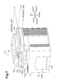
FIG. 10 is a sectional view taken along line I-I of FIG. 9.
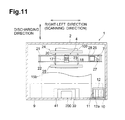
FIG. 11 is a sectional view taken along line II-II of FIG. 10.
FIG. 12 is a perspective view of a paper cassette.
FIG. 13 is a block diagram schematically showing an electric configuration of the ink jet printer of FIG. 8.
FIGS. 14 and 15 are front views of ink jet printers having different modified forms of a terminal receiving member.
FIGS. 16 and 17 are perspective views of further different modified forms of the terminal receiving member.
DETAILED DESCRIPTION
Hereinafter, one or more aspects of the disclosure are described.
An image forming apparatus 1 according to an illustrative embodiment, illustrated in FIG. 1, is one practical example of an image forming apparatus according to aspects of the present disclosure. In short, the matters specifying the claimed invention are not limited to particular members, structures or the like exemplified by the following illustrative embodiments. In the following, the illustrative embodiments are described with reference to the drawings.
First Illustrative Embodiment
1. General Configuration of the Image Forming Apparatus
Referring first to FIG. 1, a housing 103 of an image forming apparatus 101 according to the present illustrative embodiment configures a design surface appearance of the image forming apparatus 101. In the apparatus main body, namely, in the housing 103, an image forming unit 105 for forming an image on a sheet such as a paper sheet is accommodated as shown in FIG. 2.
It is to be noted that the image forming unit 105 in the present illustrative embodiment is an image forming unit of the monochromatic type or an image forming member of the xerographic type having a photosensitive member 105A, a charger 105B, an exposure unit 105C, a transfer member 105D, a fixing unit 105E and so forth.
The photosensitive member 105A carries a developer image thereon. The charger 105B charges the photosensitive member 105A. The exposure unit 105C exposes the surface of the charged photosensitive member 105A to form an electrostatic latent image on the surface of the photosensitive member 105A. Then, if charged developer is supplied to the photosensitive member 105A on which the electrostatic latent image is formed, then a developer image is carried on the surface of the photosensitive member 105A.
The transfer member 105D is configured to transfer the developer image carried on the photosensitive member 105A to a sheet and is disposed at a position opposing to the photosensitive member 105A. The fixing unit 105E fixes the developer image transferred to the sheet. It is to be noted that the fixing unit 105E in the present illustrative embodiment is a fixing device of the heating type which heats the developer to deposit the developer onto the sheet.
Then, the sheet for which image formation is completed is discharged from a discharge port 107A to a discharge tray 107. It is to be noted that the discharge port 107A in the present illustrative embodiment is open to the forward side at a rearward side upper portion of the housing 103. The discharge tray 107 is configured to have an inclined face which is inclined downward toward the discharge port 107A.
Below the image forming unit 105 in the housing 103, a feed tray 109 is disposed which has a receiving portion 109A on which a plurality of sheets can be placed. The feed tray 109 is removably mounted on the apparatus main body, namely, on the housing 103. In the present illustrative embodiment, the feed tray 109 may be mounted on and removed from the housing 103 by moving the feed tray 109 in forward and backward directions.
Sheets placed in a stacked state on the feed tray 109 are successively fed to the image forming unit 105 from the upper end side of the feed tray 109 in the stacking direction.
2. Antenna Portion for Short-Range Wireless Communication
In the housing 103, a communication board 111 having an antenna portion 111A for short-range wireless communication is disposed as shown in FIG. 2. Further, the image forming apparatus 101 according to the present illustrative embodiment carries out short-range wireless communication with a communication device such as a portable apparatus (not shown) through the antenna portion 111A. By such short-range wireless communication, for example, the following acts can be carried out.
In particular, (a) the image forming apparatus 101 can be operated through an operation unit of the communication device. (b) Image data to be formed on a sheet can be transmitted from the communication device to the image forming apparatus 101 directly without passing through a computer or the like so that it is printed by the image forming apparatus 101. Or, (c) by authenticating an owner of the communication device, an operation permitted in advance to the owner is executed while operations other than the permitted operation are prohibited.
A communication unit 111B which corresponds to the antenna portion 111A is provided at a position on the outer surface of the housing 103 at which the communication unit 111B may be seen without obstruction from the upper side as shown in FIG. 1.
In particular, the image forming apparatus 101 does not have any portion above the communication unit 111B. Therefore, in a region from above the communication unit 111B to the communication unit 111B, nothing blocks the field of vision of the user, and the user may see the communication unit 111B without obstruction from the upper side.
In particular, the communication unit 111B is provided on an upper face of a forward side of the housing 103. An operation region 113 which is operated by a user is provided on the front side of the housing 103. In particular, the communication unit 111B in the present illustrative embodiment is provided, at least in the forward and backward direction of the housing 103, on the same side as the operation region 113.
More particularly, the communication unit 111B is provided at a position displaced toward the front side with respect to the discharge tray 107 in the forward and backward direction of the housing 103. It is to be noted that the “front face side in the forward and backward direction of the housing 103” is a side of the housing 103 on which the operation region 113 is provided, for example, with respect to the center in the forward and backward direction.
Therefore, if the antenna portion 111A and the charger 105B are projected to a horizontal plane, then the antenna portion 111A projected to the horizontal plane is displaced with respect to the charger 105B projected to the horizontal plane. In other words, the antenna portion 111A projected to the horizontal plane is positioned on the opposite side to the fixing unit 105E projected to the horizontal plane across the charger 105B projected to the horizontal plane.
Further, the communication unit 111B is formed in a horizontally planar state as shown in FIG. 2. It is to be noted that the term “horizontal” signifies a horizontal state of such a degree that, when a communication device is placed on the communication unit 111B, the communication device does not slip down from the communication unit 111B, namely, from the housing 103. Further, the term “planar state” signifies a planar state of such a degree that, when a communication device is placed on the communication unit 111B, the communication device does not suffer from any significant rattle.
Further, an opening 103A and a front cover 103B are provided on the forward side of the housing 103. The opening 103A establishes communication between the inside and the outside of the housing 103. The front cover 103B is assembled to the housing 103 for displacement between a position at which the front cover 103B closes the opening 103A and a position at which the front cover 103B opens the opening 103A. It is to be noted that the front cover 103B in the present illustrative embodiment opens and closes the opening 103A by rocking displacement thereof around a lower end side thereof.
The antenna portion 111A is disposed on the upper side with respect to an upper end of the front cover 103B. In other words, the antenna portion 111A is positioned at a location displaced to the outer side from an outer edge of the opening 103A as viewed from the opening direction of the opening 103A, in the present illustrative embodiment, from the forward and backward direction.
It is to be noted that the opening 103A can allow a dismounting or mounting operation of a process unit 105F or a removing operation of a jamming sheet or the like to be carried out. Incidentally, the process unit 105F is a casing in which the photosensitive member 105A, developer and so forth can be accommodated.
3. Characteristics of the Image Forming Apparatus
In the present illustrative embodiment, since the communication unit 111B is provided at a position at which it can be seen without obstruction from the upper side, a communication device such as a smartphone can be brought close to or into contact with the communication unit 111B readily. Accordingly, since wireless communication between the antenna portion 111A and a communication device can be established reliably, the operability of the image forming apparatus which utilizes the communication device can be improved.
In the present illustrative embodiment, the antenna portion 111A is disposed such that the antenna portion 111A projected to the horizontal plane is displaced from the charger 105B projected to the horizontal plane. Therefore, the distance between the antenna portion 111A and the charger 105B may be made comparatively great. Accordingly, a situation in which the antenna portion 111A suffers from electric noise from the charger 105B may be suppressed.
In the present illustrative embodiment, the antenna portion 111A is disposed such that the antenna portion 111A projected to the horizontal plane is positioned on the opposite side to the fixing unit 105E projected to the horizontal plane across the charger 105B projected to the horizontal plane. Therefore, the antenna portion 111A can be spaced from the fixing unit 105E. Accordingly, where the fixing unit 105E of the heating type is adopted, the antenna portion 111A can be protected against the heat of the fixing unit 105E.
In the present illustrative embodiment, since the communication unit 111B is provided at a position displaced from the discharge tray 107, such a failure that a sheet placed on the discharge tray 107 makes an obstacle when a communication device is brought close to or into contact with the communication unit 111B can be prevented.
In the present illustrative embodiment, since the communication unit 111B is positioned on the upper face of the forward side of the housing 103, the user can bring a communication device close to or into contact with the communication unit 111B readily.
In the present illustrative embodiment, since the communication unit 111B is formed so as to have a horizontal planar shape, a communication device may be left in a state in the communication device when it is placed on the communication unit 111B. Accordingly, the user need not hold the communication device, and consequently, the image forming apparatus is improved in convenience in use.
In the present illustrative embodiment, since the antenna portion 111A is disposed on the upper side with respect to an upper end of the front cover 103B, the user can bring a communication device close to or into contact with the communication unit 111B readily, independent of the position of the front cover 103B.
In particular, if the communication unit 111B is provided otherwise on a movable member such as the front cover 103B, then since the position of the communication unit 111B is displaced depending upon the state of the movable member, it is difficult to bring a communication device close to or into contact with the communication unit 111B.
Second Illustrative Embodiment
The communication unit 111B in the first illustrative embodiment is provided at a position displaced forwardly with respect to the discharge tray 107 in the forward and backward direction of the housing 103. However, in the present illustrative embodiment, the communication unit 111B is provided at a position displaced with respect to the discharge tray 107 in the leftward and rightward direction of the housing 103 as shown in FIG. 4.
Further, the communication unit 111B in the present illustrative embodiment is formed in an inclined planar shape which extends downwardly toward the forward side. Further, a holding member 111C for holding a communication device thereon is provided on the lower end side of the communication unit 111B.
It is to be noted that the inclined face of the housing 103 which configures the communication unit 111B may have any configuration. For example, the inclined face of the housing 103 may be formed integrally with a top cover 103C which configures the housing 103 or may be formed as a separate member from the top cover 103C and assembled to the top cover 103C.
Further, the communication unit 111B in the present illustrative embodiment is formed in an inclined planar shape which is inclined downwardly toward the forward side. Therefore, for example, where a display unit is provided on a communication device, the user can visually recognize the display unit readily while the communication device remains placed on the communication unit 111B.
Further, in the present illustrative embodiment, since the holding member 111C for holding a communication device is provided on the lower end side of the communication unit 111B, the user need not continue to hold the communication device. Accordingly, the image forming apparatus can be improved in convenience in use.
It is to be noted that, while the communication unit 111B in FIG. 4 is provided on the rear face side, namely, on the rearward side with respect to the center in the forward and backward direction, the present illustrative embodiment is not limited to this, but the communication unit 111B may be provided on the forward side.
Further, while, in FIG. 4, the holding member 111C is configured from a groove extending in the leftward and rightward direction, the present illustrative embodiment is not limited to this, but the holding member 111C may be configured, for example, from a projection which projects upwardly from the top cover 103C or a like element. Or, a flat face of the top cover 103C may be utilized as the holding member 111C, or else, the holding member 111C may be eliminated.
Third Illustrative Embodiment
In the present illustrative embodiment depicted in FIG. 5, an image forming apparatus 101 with which a reading unit 120 for reading in image information described on a manuscript is integrated is shown.
In particular, the housing 103 in the present illustrative embodiment includes a first housing member 131 and a second housing member 132. The first housing member 131 accommodates the image forming unit 105 and corresponds to the housing in the first illustrative embodiment.
The second housing member 132 accommodates the reading unit 120 therein and is positioned at a location spaced above the first housing member 131 with a space 130A left therebetween. In short, the reading unit 120 is positioned at the location spaced above the discharge tray 107 with the space 130A therebetween.
Further, at a position of the second housing member 132 displaced from the reading unit 120, an operation panel 132A which configures part of the second housing member 132 and has the operation region 113 is provided. The communication unit 111B is provided on the operation panel 132A.
Accordingly, if the reading unit 120 and the antenna portion 111A are projected to a horizontal plane, then the antenna portion 111A projected to the horizontal plane is displaced from the reading unit 120 projected to the horizontal plane. Particularly, in the present illustrative embodiment, the operation panel 132A is displaced frontward with respect to the reading unit 120 and is provided at a position at which the operation panel 132A can be seen from the upper side without obstruction.
Therefore, in the present illustrative embodiment, the user may bring a communication device close to or into contact with the communication unit 111B readily without being obstructed by the reading unit 120.
Further, since the communication unit 111B is provided on the second housing member 132 disposed on the upper side with respect to the first housing member 131, the user can bring a communication device close to or into contact with the communication unit 111B readily from the upper side.
Although the communication unit 111B in the present illustrative embodiment is configured in an inclined planar shape similar to that in the second illustrative embodiment, the holding member 111C is not provided on the communication unit 111B as shown in FIG. 5. However, the present illustrative embodiment is not limited to this, but the holding member 111C may be provided otherwise on the lower end side of the communication unit 111B or the communication unit 111B may otherwise be formed in a horizontal planar shape.
Further, where the holding member 111C is provided, it may be configured such that, for example, as shown in FIG. 6, a recessed portion 111D forms a recess in the upper face of the operation panel 132A that allows a communication device to be received therein. If such a configuration as just described is adopted, then since a communication device can fit into the recessed portion 111D, the recessed portion 111D can function as the holding member 111C.
Fourth Illustrative Embodiment
While, in the third illustrative embodiment, the communication unit 111B is provided in the second housing member 132, in the present illustrative embodiment, the communication unit 111B is provided at a position of the first housing member 131 at which the communication unit 111B can be seen without obstruction from the upper side as shown in FIG. 7.
Also in the present illustrative embodiment, if the reading unit 120 and the antenna portion 111A are projected to a horizontal plane, then the antenna portion 111A projected to the horizontal plane is displaced with respect to the reading unit 120 projected to the horizontal plane.
Therefore, also in the present illustrative embodiment, the user may bring a communication device close to or into contact with the communication unit 111B readily without being obstructed by the reading unit 120.
While the image forming units in the first to fourth illustrative embodiments described hereinabove are of the monochromatic xerography type, the present disclosure is not limited to this. In particular, the image forming unit may be of any type such as the color xerography type or the monochromatic or color ink jet type.
Further, the particular utilization form of the short-range wireless communication is not limited to that used in the illustrative embodiments described hereinabove but may be any other utilization form.
For example, a communication device having a display unit such as a liquid crystal panel may be used in such a utilization form that the display unit of the communication device functions as a display unit of the image forming apparatus through short-range wireless communication. Where the communication device is used as the display unit of the image forming apparatus, a configuration wherein the image forming apparatus does not have a display unit can be implemented. Therefore, reduction of the fabrication cost of the image forming apparatus can be anticipated.
Fifth Illustrative Embodiment
A perspective view of an ink jet printer according to the fifth illustrative embodiment is shown in FIG. 8. It is to be noted that upward, downward, leftward, rightward, forward and backward directions are defined in an installation state illustrated in FIG. 8 in which the ink jet printer is used.
Referring to FIG. 8, the ink jet printer 1 is a recording apparatus and also an image forming apparatus and includes a printer housing 2 formed from a synthetic resin material and a cover 3 attached for pivotal motion to the printer housing 2. An opening is formed at a front portion of the printer housing 2 and surrounded by an upper wall 2 a, side walls 2 b and 2 c and a bottom wall 2 d of the printer housing 2. As shown in FIG. 10, a control board 29 is disposed in a horizontal posture on an upper face of the upper wall 2 a. In the control board 29, various circuits for controlling the ink jet printer 1 are incorporated. In FIG. 11, the upper wall 2 a and the control board 29 are not shown.
Referring to FIGS. 10 and 11, the printer housing 2 accommodates a printer unit or recording unit 4 for recording an image and so forth on a recording paper sheet 100 which is recording medium, and a feeding mechanism 5 for feeding the recording paper sheet 100 to the printer unit 4. The printer housing 2 further accommodates a discharge unit 6 into which the recording paper sheet 100 recorded by the printer unit 4 is discharged. The printer housing 2 further accommodates a maintenance unit 7 for carrying out maintenance of an ink jet head 18 of the printer unit 4, and a scanner unit 8 for reading an image, characters and so forth recorded on the recording paper sheet 100. An operation panel 9 for accepting various operations for the ink jet printer 1 by a user is disposed at a front portion of an upper face of the printer housing 2. It is to be noted that a configuration of the components is hereinafter described.
Referring to FIGS. 8 and 11, an opening and closing lid 10 is attached to the right end of a front face of the printer housing 2, and a holder 12 on which ink cartridges 11 are to be mounted is disposed behind the opening and closing lid 10. The holder 12 has four cartridge mounting portions 12 a, into which four ink cartridges 11 in which inks of four colors, namely, cyan (C), magenta (M), yellow (Y) and black (BK, are stored individually, are removably mounted from the front.
Referring to FIG. 8, the cover 3 is disposed behind the operation panel 9 of the printer housing 2 and above the printer housing 2 in such a manner as to cover the upper face of the printer housing 2. Further, the cover 3 is attached to the printer housing 2 through a pivot shaft not shown provided at a rear end portion thereof such that it can be pivoted upwardly and downwardly with respect to the printer housing 2 around the pivot shaft.
Referring to FIG. 10, the feeding mechanism 5 includes a paper cassette 15 mounted on the printer housing 2, and a pickup roller 16 for picking up a recording paper sheet 100 from the paper cassette 15. The paper cassette 15 has a main tray 15 a for holding the recording paper sheets 100 in a stacked state thereon and a discharge tray 15 b provided above the main tray 15 a for receiving the recording paper sheet 100 recorded by and discharged from the printer unit 4 hereinafter described. The pickup roller 16 is disposed above the main tray 15 a and configured to rotate around a rotatable shaft provided on the printer housing 2. The pickup roller 16 is driven to rotate by a paper feed motor 80 shown in FIG. 13 to pick up the recording paper sheets 100 one by one from the main tray 15 a of the paper cassette 15. The recording paper sheet 100 picked up by the pickup roller 16 is pushed upwardly along an inclined face 15 c provided at an end portion of the paper cassette 15 and supplied to the printer unit 4.
Referring to FIGS. 10 and 11, the printer unit 4 is disposed in the printer housing 2 and carries out recording on a recording paper sheet 100. The printer unit 4 is disposed above the feeding mechanism 5. The printer unit 4 includes a carriage 17 mounted for back and forth movement in the leftward and rightward direction, namely, in a scanning direction, and an ink jet head 18 carried on the carriage 17. The printer unit 4 further includes a transport mechanism 19 for transporting a recording paper sheet 100 forwardly, namely, in a discharging direction, along a horizontal plane.
In the printer housing 2, a platen 20 for supporting a recording paper sheet 100 is disposed in a horizontal posture. Two guide rails 21 and 22 are provided above the platen 20 and extend in parallel to each other in the scanning direction. The carriage 17 is driven by a carriage driving motor 78 shown in FIG. 13 to move in the scanning direction, namely, in the leftward and rightward direction, along the two guide rails 21 and 22 in a region opposing the recording paper sheet 100 on the platen 20.
The ink jet head 18 is attached to a lower portion of the carriage 17 in a state in which a gap is provided between the ink jet head 18 and the platen 20. A lower face of the ink jet head 18 serves as an ink drop injection face 18 a to which a plurality of nozzles 23 are opened. The nozzles 23 are arrayed along the discharging direction to configure four nozzle columns for injecting inks of the four colors, namely, of cyan, magenta, yellow and block. The ink jet head 18 carried on the carriage 17 is connected to the holder 12 described hereinabove through tubes not shown such that the inks of the four colors stored in the four ink cartridges 11 mounted on the holder 12 are supplied to the ink jet head 18 through the tubes.
The ink jet head 18 is movable together with the carriage 17 not only within a range within which it is opposed to a recording paper sheet 100 transported on the platen 20 but also to positions displaced to the left and right outer sides from the range. Particularly, the position on the right side with respect to the opposing range to the recording paper sheet 100 is a standby position at which the carriage 17 stands by when the ink jet head 18 is not used. When the carriage 17 arrives at the standby position, it opposes the maintenance unit 7 hereinafter described which is disposed below the carriage 17.
The transport mechanism 19 includes two transport roller pairs 24 and 25 disposed forward and rearward in such a manner that the platen 20 and the carriage 17 are positioned therebetween. The transport roller pairs 24 and 25 are driven by a transport motor 79 shown in FIG. 13 to transport a recording paper sheet 100 forwardly, namely, in the discharging direction, between the ink jet head 18 and the platen 20.
In the printer unit 4 described above, while the carriage 17 is moved in the scanning direction, namely, in the leftward and rightward direction, ink is injected from the ink jet head 18 to a recording paper sheet 100 on the platen 20 and the recording paper sheet 100 is transported in the discharging direction by the two transport roller pairs 24 and 25 to record a desired image or characters on the recording paper sheet 100.
Referring to FIGS. 8 to 10, the above-described opening surrounded by the upper wall 2 a, side walls 2 b and 2 c and bottom wall 2 d is formed below the operation panel 9 at a front portion of the printer housing 2. The paper cassette 15 is mounted on the bottom wall 2 d under the opening. The paper cassette 15 is removable from the printer housing 2. The discharge unit 6 is formed from the discharge tray 15 b, namely, a discharge face of the discharge tray 15 b, at the top of the paper cassette 15, and an opening region above the paper cassette 15 surrounded by the discharge tray 15 b and the upper wall 2 a and side walls 2 b and 2 c of the printer housing 2. A recording paper sheet 100 recorded by the printer unit 4 is transferred forwardly by the transport roller pairs 24 and 25 and placed on the discharge tray 15 b of the discharge unit 6. In this manner, the discharge unit 6 is formed in the printer housing 2, and the recording paper sheet 100 recorded by the printer unit 4 is discharged to the discharge unit 6. The user can take out the recording paper sheet 100 placed on the discharge tray 15 b from the front of the discharge unit 6.
Referring to FIG. 11, the maintenance unit 7 is disposed at a position on the right side of the platen 20, namely, at a position opposing the ink jet head 18 when the ink jet head 18 stands by at the standby position. The maintenance unit 7 includes a cap member 26 which closely contacts with the ink drop injection face 18 a of the ink jet head 18 to cover the openings of the nozzles 23. The maintenance unit 7 further includes a suction pump 27 for compulsorily discharging ink from the nozzles 23 covered with the cap member 26 to the cap member 26, a wiper 28 for wiping off the ink sticking to the ink drop injection face 18 a, and so forth.
Referring to FIG. 10, the scanner unit 8 includes a carriage 30 movable back and forth in the leftward and rightward direction, and an image scanner 31 carried on the carriage 30. At an upper portion in the printer housing 2, a guide rail 32 is provided such that it extends in parallel to the scanning direction, namely, in the leftward and rightward direction. When the carriage 30 is driven by a carriage driving motor not shown, it moves in the scanning direction, namely, in the leftward and rightward direction, along the guide rail 32 within a range opposing a plate member 14 fitted in an opening 13 in the printer housing 2. Thereupon, the recording paper sheet 100 is scanned by the image scanner 31. In other words, the ink jet printer 1 of the present illustrative embodiment is configured as a composite machine which can execute printing, scanning, copying and so forth.
Referring to FIGS. 8 and 10, the operation panel 9 is provided at a front portion of an upper face of the printer housing 2 and above the discharge unit 6, and has various operation buttons 33 to 36, a liquid crystal display unit 37 of the touch panel type, and so forth. The liquid crystal display unit 37 displays various kinds of information thereon, and the user can operate the liquid crystal display unit 37 to instruct the ink jet printer 1 to carry out various operations. A large number of conductors for the liquid crystal display unit 37 and so forth are disposed on the operation panel 9. A panel controlling board 38 for controlling the operation panel 9 is provided below the operation panel 9 as shown in FIG. 10. A panel controlling circuit 81 shown in FIG. 13 for controlling the operation panel 9 and associated elements is incorporated in the panel controlling board 38.
The ink jet printer 1 according to the present illustrative embodiment carries out communication by the NFC (Near Field Communication), which is a type of short-range wireless communication, with a communication terminal 200 such as a portable telephone set or a smartphone. Consequently, the ink jet printer 1 can receive recording data of an image or characters from the communication terminal 200. In the following, a configuration of the ink jet printer 1 which relates to the short-range wireless communication is described.
Referring to FIGS. 8 to 11, a terminal receiving member 39 on which the communication terminal 200 can be placed is provided in the discharge unit 6. In particular, the terminal receiving member 39 is a recessed portion provided on the discharge tray 15 b on which a recording paper sheet 100 recorded by the printer unit 4 is to be placed as shown also in FIG. 12. Further, the terminal receiving member 39 is formed in a substantially rectangular shape at a central portion at a front end portion of the discharge tray 15 b. Furthermore, the terminal receiving member 39 has an extent sufficient to accommodate the communication terminal 200 therein and has a depth with which the communication terminal 200 does not project upwardly from the terminal receiving member 39 in a state in which the communication terminal 200 is mounted in the terminal receiving member 39. The user can place the communication terminal 200 readily into the terminal receiving member 39 from the front of the discharge unit 6. Below the terminal receiving member 39 of the paper cassette 15, a mark 40 which indicates the position of the terminal receiving member 39 and is, in the present illustrative embodiment, an arrow mark, is applied.
According to FIG. 10, an antenna 41 serving as a communication unit may communicate by the NFC with the communication terminal 200 received in the terminal receiving member 39. In particular, the antenna 41 is a loop antenna and is disposed on a lower face, namely, the reverse face, of the panel controlling board 38. Further, the antenna 41 is disposed on a lower face of the panel controlling board 38 disposed in a substantially horizontal posture such that the loop portion thereof lies substantially in parallel to the horizontal direction. Further, the antenna 41 is disposed substantially directly above the terminal receiving member 39 such that the distance L between the terminal receiving member 39 and the antenna 41 is within 10 cm which is a maximum communication distance by the NFC. Another loop antenna not shown is built in the communication terminal 200 such that the loop portion thereof extends in parallel to a direction perpendicular to the thickness direction of the communication terminal 200. Therefore, if the communication terminal 200 is installed on the horizontal bottom face of the terminal receiving member 39, then the loop portions of the antenna 41 of the ink jet printer 1 and the antenna of the communication terminal 200 oppose substantially in parallel to each other.
If the communication terminal 200 is received in the terminal receiving member 39, then communication by NFC is carried out between the antenna 41 on the ink jet printer 1 side and the antenna on the communication terminal 200 side. More particularly, if a magnetic field is generated from one of the loop antenna 41 of the ink jet printer 1 side and the loop antenna of the communication terminal 200 side, then induced current is generated in the other antenna by electromagnetic induction. Consequently, data is transmitted from the one antenna to and received by the other antenna. Then, if the transmission (magnetic field generation) function and the reception (induced current generation) function of both antennae are changed over alternately, then bidirectional communication can be achieved between the ink jet printer 1 and the communication terminal 200.
Now, an electric configuration of the ink jet printer 1 is described. FIG. 13 is a block diagram schematically showing an electric configuration of the ink jet printer 1. Referring to FIG. 13, the control board 29 for controlling operation of the ink jet printer 1 is connected for data communication with a PC (personal computer) 300, which is an external apparatus, through an input/output interface (I/F) 71 such that recording data of an image or characters to be recorded are inputted from the PC 300 to the control board 29. Further, the panel controlling board 38 in which the panel controlling circuit 81 is incorporated is connected to the control board 29 such that various operations from the operation panel 9 are inputted as various signals relating to operation of the ink jet printer 1 to the control board 29 through the panel controlling circuit 81.
Various circuits are incorporated in the control board 29. In particular, a recording controlling circuit 72 for controlling recording operation of the printer unit 4, which includes the ink jet head 18 and so forth, based on received recording data, and a paper feeding controlling circuit 73 for controlling paper feeding operation by the feeding mechanism 5 are incorporated. Further, a maintenance controlling circuit 74 for controlling maintenance operation by the maintenance unit 7, a scanner controlling circuit 75 for controlling scanning of a recording paper sheet by the scanner unit 8 and a communication controlling circuit 76 for controlling data communication by the NFC with the communication terminal 200 are incorporated.
In the following, communication by NFC controlled by the communication controlling circuit 76, particularly reception of recording data, is described. The communication controlling circuit 76 is connected to a communication module 41 a of the antenna 41. In the ink jet printer 1, communication with the communication terminal 200 by NFC is started by the user operating the liquid crystal display unit 37 of the operation panel 9 to input a predetermined instruction. When a communication starting instruction is inputted, the communication controlling circuit 76 carries out communication with the communication terminal 200. At this time, if the communication terminal 200 is placed into the terminal receiving member 39 by the user and then the communication with the communication terminal 200 is carried out normally, then the reception of the recording data is completed. On the other hand, even if a predetermined period of time elapses, if the communication with the communication terminal 200 is not carried out normally, then a message representing that communication is not carried out normally is displayed on the liquid crystal display unit 37. In this manner, recording data received by the antenna 41 are sent from the communication controlling circuit 76 to the recording controlling circuit 72 similarly to recording data received from the PC 300, and the recording operation by the printer unit 4 is controlled based on the recording data.
The ink jet printer 1 according to the present illustrative embodiment described above includes a printer housing 2, a printer unit 4 disposed in the printer housing 2 for carrying out recording on a recording paper sheet 100, a discharge unit 6 formed in the printer housing 2 for receiving the recording paper sheet 100 recorded by the printer unit 4 and discharged thereto, a terminal receiving member 39 provided on the discharge unit 6 for receiving a communication terminal 200 placed therein, and an antenna 41 for communicating with the communication terminal 200 placed in the terminal receiving member 39 by short-range wireless communication.
In the ink jet printer 1 according to the present illustrative embodiment configured in such a manner as described above, the terminal receiving member 39 in which the communication terminal 200 can be received is provided on the discharge unit 6 to which a recording paper sheet 100 is discharged. The discharge unit 6 receives the recording paper sheet 100 discharged thereto and has a large opening to this side, namely, to the user side, so that the user can take out the discharged recording paper sheet 100 therethrough. Accordingly, it is easy for the user to place the communication terminal 200 into such a discharge unit 6 as just described. Further, since the terminal receiving member 39 is provided on the discharge unit 6, a vacant space can be utilized effectively and a receiving space for the communication terminal 200 can be assured without increasing the size of the apparatus. Further, since the communication terminal 200 is received in the discharge unit 6 which has a large opening, the communication terminal 200 can be visually recognized readily by the user, and the communication terminal 200 can be prevented from being left in the terminal receiving member 39.
Further, since the terminal receiving member 39 is provided on the discharge tray 15 b of the discharge unit 6 on which a recording paper sheet 100 recorded by the printer unit 4 is to be placed, the user can place the communication terminal 200 readily into the terminal receiving member 39.
Further, since the terminal receiving member 39 is a recessed portion formed on the discharge tray 15 b of the discharge unit 6 and capable of accommodating the communication terminal 200 therein, the communication terminal 200 is accommodated into the recessed portion formed on the discharge tray 15 b of the discharge unit 6. Consequently, when a recording paper sheet 100 is discharged, it is less likely to contact the communication terminal 200.
Further, the operation panel 9 and the panel controlling board 38 for controlling the operation panel 9 are disposed above the discharge unit 6 and the antenna 41 is disposed on the panel controlling board 38. Therefore, communication between the communication terminal 200 and the antenna 41 can be carried out reliably. Further, the panel controlling board 38 is positioned on the reverse side of the operation panel 9. Namely, the operation panel 9 is positioned on the opposite side to the communication terminal 200 across the panel controlling board 38. Accordingly, wireless communication between the antenna 41 provided on the panel controlling board 38 and the communication terminal 200 is not obstructed by the operation panel 9 which includes a large number of conductors.
Further, since the mark 40 indicating the position of the terminal receiving member 39 may be applied, the user can readily recognize the place at which the communication terminal 200 is to be placed.
While the fifth illustrative embodiment of the present disclosure is described above, the mode to which the present disclosure can be applied is not limited to the illustrative embodiment described hereinabove but can be changed suitably without departing from the subject matter of the present disclosure.
In particular, in a recording apparatus according to a modification, a terminal receiving member 42 is provided at a position spaced from the discharge tray 15 b of the discharge unit 6 as shown in FIG. 14. In particular, referring to FIG. 14, the terminal receiving member 42 is a table provided on the discharge unit 6 and extending horizontally from the side wall 2 b of the printer housing 2 above the discharge tray 15 b such that the communication terminal 200 can be placed on the table. According to the present modification, since the terminal receiving member 42 is provided at a position spaced from the discharge tray 15 b of the discharge unit 6, the communication terminal 200 is placed at a position spaced from the discharge tray 15 b of the discharge unit 6. Consequently, a recording paper sheet 100 discharged along the discharge tray 15 b is less likely to contact the communication terminal 200. Further, since the distance of the communication terminal 200 to the antenna 41 provided on the panel controlling board 38 is reduced in comparison with the fifth illustrative embodiment described above, wireless communication between the antenna 41 and the communication terminal 200 is enhanced.
In a recording apparatus according to another modification, a terminal receiving member 43 is a groove which is formed in a region of the discharge tray 15 b of the discharge unit 6 on the end side in the widthwise direction of a recording paper sheet 100 perpendicular to the discharging direction of the recording paper sheet 100 and extends in the discharging direction of the recording paper sheet 100 as shown in FIGS. 15 and 16. In this instance, the antenna 41 is provided in parallel to the terminal receiving member 43. For example, the antenna 41 can be provided in parallel to the terminal receiving member 43 on a cartridge controlling board not shown, in which a cartridge controlling circuit not shown for controlling the ink cartridges 11 is incorporated, or on a side face of the printer housing 2. According to this modification, if the communication terminal 200 of a flattened shape is inserted into the groove formed at the end portion of the discharge unit 6 in a state in which the communication terminal 200 stands uprightly, then the communication terminal 200 can be disposed along an inner side face of the discharge unit 6. Accordingly, a discharged recording paper sheet 100 is less likely to contact the communication terminal 200.
In a recording apparatus according to a further modification, an upper face of an auxiliary tray 44 serves as a terminal receiving member 45 by which the communication terminal 200 is received as shown in FIG. 17. The auxiliary tray 44 can move out from the discharge tray 15 b of the discharge unit 6 to the discharging side of a recording paper sheet 100. In particular, the auxiliary tray 44 is attached to the discharge tray 15 b through a pivot shaft not shown provided at a rear end portion thereof such that it is pivoted around the pivot shaft to move out to the discharging side of a recording paper 100 from the discharge tray 15 b. By this auxiliary tray 44, a recording paper sheet 100 discharged to the discharging side is prevented from moving out from the discharge unit 6. In this instance, the antenna 41 is provided on the auxiliary tray 44. According to the present modification, since the upper face of the auxiliary tray 44 is the terminal receiving member 45 by which the communication terminal 200 is to be received, when the communication terminal 200 is mounted on the auxiliary tray 44 moved out from the discharge unit 6, a recording paper sheet 100 discharged from the discharge unit 6 is prevented with a higher degree of certainty from moving out by the communication terminal 200. Further, since the antenna 41 is provided on the auxiliary tray 44, the distance between the communication terminal 200 provided on the auxiliary tray 44 and the antenna 41 is very short, and consequently, wireless communication between them can be carried out reliable. While the auxiliary tray 44 in the present modification is provided for pivotal motion on the discharge tray 15 b, it may otherwise be provided for sliding movement on the discharge tray 15 b such that it can be drawn out forwardly.
The terminal receiving member 45 may otherwise be provided on an upper face of the main tray 15 a in the inside of the paper cassette 15. In this instance, the antenna 41 is provided on the main tray 15 a.
Further, since the antenna 41 is connected to the communication module 41 a, it can be provided on a board, in the fifth illustrative embodiment described hereinabove, on the panel controlling board 38. Here, to provide a board for exclusive use for the antenna 41 in order to mount the antenna 41 is not preferable because of increase of the cost, increase of the scale of the apparatus and so forth. Therefore, preferably the antenna 41 is provided on an ink cartridge board as in the modification described hereinabove or on the control board 29. Where the antenna 41 is provided on the control board 29, the terminal receiving member 45 may be provided on the discharge tray 15 b below the antenna 41.
Further, while, in the fifth illustrative embodiment described hereinabove, NFC is applied to carry out short-range wireless communication between the ink jet printer 1 and the communication terminal 200, alternatively an RFID (Radio Frequency Identification) tag or the like may be used to carry out short-range wireless communication. Further, the communication terminal is not limited to a portable telephone set, a smartphone or the like but may be an IC (Integrated Circuit) card, an IC tag or the like. Further, the data communicated by the short-range wireless communication is not limited to recording data but may be data such as log-in information to an ink jet printer.
Further, while, in the fifth illustrative embodiment described hereinabove, the upper face of the paper cassette 15 serves as the discharge tray 15 b, the paper cassette 15 and the discharge tray 15 b may not be formed as a unitary member but may be provided at positions spaced from each other while the upper face of the paper cassette 15 does not serve as the discharge tray 15 b.
According to the aspects of the discloser, an image forming apparatus comprises a housing, an image forming unit, a discharge tray, a terminal receiving member, and an antenna.
The image forming unit disposed in the housing and configured to form an image on a sheet.
The discharge tray disposed in the housing and configured to receive the sheet on which an image is formed by the image forming unit. The terminal receiving member disposed on the discharge tray and configured to receive a communication terminal thereon. The antenna configured to communicate with the communication terminal received on the terminal receiving member by short-range wireless communication.
In the image forming apparatus, the terminal receiving member is a recessed portion formed on the discharge tray and configured to hold the communication terminal therein.
In the image forming apparatus, the terminal receiving member is a groove formed at a side of the discharge tray, the groove extending along a discharging direction in which a sheet is discharged from the image forming unit.
In the image forming apparatus, an operation unit and a panel controlling board configured to control the operation unit are disposed above the discharge tray, and the antenna is disposed on the panel controlling board.
In the image forming apparatus, the discharge tray comprises an auxiliary tray configured to extend from the discharge tray in a discharging direction in which a sheet is discharged from the image forming unit, and the terminal receive member is located on a surface of the auxiliary tray, wherein the surface is the upper face of the auxiliary tray when the auxiliary tray is extended.
In the image forming apparatus, an indicator identifying a position of the terminal receiving member is disposed on a discharge unit.
According to the aspects of the discloser, an image forming apparatus comprises a housing, an image forming unit, a discharge tray, a terminal receiving member, and an antenna.
The image forming unit disposed in the housing and configured to form an image on a sheet. The discharge tray disposed in the housing and configured to receive the sheet on which an image is formed by the image forming unit. The terminal receiving member disposed in and coupled to the housing and configured to receive a communication terminal thereon and disposed at a position spaced away from and overlapping the discharge tray. The antenna configured to communicate with the communication terminal received on the terminal receiving member by short-range wireless communication.
Further, while the ink jet printer 1 in the fifth illustrative embodiment described above is a recording apparatus of the ink jet type, the recording method is not limited to the ink jet type but may be that of a laser type, an LED (Light Emitting Diode) type or the like. Where the recording method is that of the ink jet type, an ink jet method of a line type may be applied.
The present disclosure includes any invention which is consistent with the spirit and scope of the disclosure and is not restricted to the illustrative embodiments described hereinabove but the components of the illustrative embodiments may be used in suitable combinations.

Claims (11)

What is claimed is:
1. An image forming apparatus comprising:
a housing having a lower portion and an upper portion, the upper portion being positioned on an upper side of the lower portion;
an image forming unit configured to form an image on a sheet, the image forming unit being accommodated in the lower portion and configured to discharge the sheet in a first direction; and
a reading unit configured to read an image of an original, the reading unit being accommodated in the upper portion,
wherein the upper portion further comprises:
an operation panel positioned closer to a front side of the upper portion than to a rear side of the upper portion in the first direction, the operation panel being continuous and configured in an inclined planar shape inclined towards an uppermost portion of the upper portion relative to the first direction, and extending in a second direction perpendicular to the first direction,
an antenna device provided under the operational panel and configured for a short-range wireless communication with a maximum communication distance of 10 cm; and
an operation region configured to receive user operations provided on the operation panel separated from the antenna device, a distance between a first edge of the operation panel and the antenna device being less than a distance between the first edge of the operation panel and the operation region in the second direction,
wherein a second edge of the operation panel closest to the lower portion is parallel to the second direction,
wherein the image forming unit comprises:
a photosensitive member configured to carry a developer image,
a charger configured to charge the photosensitive member,
an exposure unit configured to expose the charged photosensitive member,
a transfer member configured to transfer the developer image carried on the photosensitive member to the sheet,
a fixing unit configured to fix the developer image transferred to the sheet, and
a discharge tray configured to receive the sheet discharged from the image forming unit toward a front side of the housing,
wherein the image forming apparatus further comprises a communication unit being disposed at a position on the operation panel of the upper portion, the communication unit configured to receive a communication device for short-range wireless communication with the antenna device, and
wherein when the antenna device and the charger are projected to a horizontal plane that is parallel to a bottom side of the image forming unit opposite to the upper side of the image forming unit, the antenna device projected to the horizontal plane is displaced with respect to the charger projected to the horizontal plane.
2. The image forming apparatus according to claim 1, wherein the projection of the charger on the horizontal plane is positioned between the projections of the antenna device and the fixing unit.
3. The image forming apparatus according to claim 1, wherein the fixing unit is positioned closer to a back face of the housing than a front face of the housing.
4. The image forming apparatus according to claim 1, wherein the communication unit is formed in a horizontal planar shape.
5. The image forming apparatus according to claim 1, wherein the communication unit is formed on an inclined face of the operation panel extending downward toward the front side of the upper portion and the fixing unit is positioned closer to a back face of the housing than a front face of the housing.
6. The image forming apparatus according to claim 5, further comprising:
a holding member configured to hold a communication device received by the communication unit for short-range wireless communication with the antenna device, the antenna device being disposed on a bottom side of the communication unit.
7. The image forming apparatus according to claim 1, wherein the projection of the antenna device to the horizontal plane is displaced with respect to a projection of the reading unit to the horizontal plane.
8. The image forming apparatus according to claim 1, wherein the position at which the communication unit receives the communication device overlaps the antenna device in a vertical direction.
9. The image forming apparatus according to claim 1,
wherein the image forming unit comprise:
a photosensitive member configured to carry a developer image,
a charger configured to charge the photosensitive member,
an exposure unit configured to expose the charged photosensitive member,
a transfer member configured to transfer the developer image carried on the photosensitive member to the sheet,
a fixing unit configured to fix the developer image transferred to the sheet, and
a discharge tray configured to receive the sheet discharged from the image forming unit toward a front side of the housing,
wherein the image forming apparatus further comprises a communication unit being disposed at a position on the operation panel of the upper portion, the communication unit configured to receive a communication device for short-range wireless communication with the antenna device, and
wherein when the antenna device and the fixing unit are projected to a horizontal plane that is parallel to a bottom side of the image forming unit opposite to the upper side of the image forming unit, the antenna device projected to the horizontal plane is displaced with respect to the fixing unit projected to the horizontal plane.
10. The image forming apparatus according to claim 1, wherein the operation panel includes a display unit.
11. The image forming apparatus according to claim 1, wherein the upper portion of the housing is positioned on the upper side of the lower portion in a third direction perpendicular to the first direction and the second direction.
US13/852,795 2012-04-25 2013-03-28 Image forming apparatus with communication device Active US9509873B2 (en)

Priority Applications (3)

Application Number Priority Date Filing Date Title
US15/349,049 US9900453B2 (en) 2012-04-25 2016-11-11 Image forming apparatus
US15/862,395 US10778857B2 (en) 2012-04-25 2018-01-04 Image forming apparatus
US17/018,498 US11811989B2 (en) 2012-04-25 2020-09-11 Image forming apparatus including antenna in cover

Applications Claiming Priority (4)

Application Number Priority Date Filing Date Title
JP2012-100080 2012-04-25
JP2012100080A JP6064361B2 (en) 2012-04-25 2012-04-25 Image forming apparatus
JP2012-139682 2012-06-21
JP2012139682A JP2014004687A (en) 2012-06-21 2012-06-21 Recording apparatus

Related Child Applications (1)

Application Number Title Priority Date Filing Date
US15/349,049 Continuation US9900453B2 (en) 2012-04-25 2016-11-11 Image forming apparatus

Publications (2)

Publication Number Publication Date
US20130286433A1 US20130286433A1 (en) 2013-10-31
US9509873B2 true US9509873B2 (en) 2016-11-29

Family

ID=47997240

Family Applications (3)

Application Number Title Priority Date Filing Date
US13/852,795 Active US9509873B2 (en) 2012-04-25 2013-03-28 Image forming apparatus with communication device
US15/349,049 Active US9900453B2 (en) 2012-04-25 2016-11-11 Image forming apparatus
US15/862,395 Active US10778857B2 (en) 2012-04-25 2018-01-04 Image forming apparatus

Family Applications After (2)

Application Number Title Priority Date Filing Date
US15/349,049 Active US9900453B2 (en) 2012-04-25 2016-11-11 Image forming apparatus
US15/862,395 Active US10778857B2 (en) 2012-04-25 2018-01-04 Image forming apparatus

Country Status (3)

Country Link
US (3) US9509873B2 (en)
EP (2) EP3506018B1 (en)
CN (3) CN107015455A (en)

Cited By (1)

* Cited by examiner, † Cited by third party
Publication number Priority date Publication date Assignee Title
US20150280306A1 (en) * 2014-03-27 2015-10-01 Brother Kogyo Kabushiki Kaisha Communication device provided with antenna for near field wireless communication

Families Citing this family (28)

* Cited by examiner, † Cited by third party
Publication number Priority date Publication date Assignee Title
JP5998704B2 (en) * 2012-07-24 2016-09-28 ブラザー工業株式会社 Image reading device
JP2014096717A (en) 2012-11-09 2014-05-22 Brother Ind Ltd Image forming apparatus
JP6230226B2 (en) 2012-11-29 2017-11-15 キヤノン株式会社 Image forming apparatus
US9083837B2 (en) * 2013-03-26 2015-07-14 Xerox Corporation System and method for keyed operation of devices using near field communication
JP6176078B2 (en) * 2013-11-25 2017-08-09 ブラザー工業株式会社 Image forming apparatus
JP6270137B2 (en) 2014-03-12 2018-01-31 ブラザー工業株式会社 Image forming apparatus
JP6260387B2 (en) * 2014-03-25 2018-01-17 セイコーエプソン株式会社 Printing apparatus and printing apparatus control program
JP6187454B2 (en) * 2014-12-29 2017-08-30 コニカミノルタ株式会社 Image processing device
JP2016124226A (en) 2015-01-06 2016-07-11 セイコーエプソン株式会社 Printer
JP6131985B2 (en) 2015-05-28 2017-05-24 富士ゼロックス株式会社 Image forming apparatus
JP6670012B2 (en) * 2015-07-22 2020-03-18 キヤノン株式会社 Image forming device
JP2017087462A (en) * 2015-11-04 2017-05-25 船井電機株式会社 Electronic equipment
JP6725869B2 (en) 2016-02-26 2020-07-22 セイコーエプソン株式会社 Reader and recorder
JP2017154374A (en) * 2016-03-02 2017-09-07 京セラドキュメントソリューションズ株式会社 Image formation device
CN108778763A (en) * 2016-04-15 2018-11-09 惠普发展公司有限责任合伙企业 Printing device with wireless network module
JP2017204809A (en) * 2016-05-13 2017-11-16 京セラドキュメントソリューションズ株式会社 Image reader and image forming apparatus
CN205942253U (en) * 2016-08-08 2017-02-08 珠海赛纳打印科技股份有限公司 Image formation device
JP6678752B2 (en) * 2016-08-31 2020-04-08 三菱電機株式会社 rice cooker
JP2018060090A (en) * 2016-10-06 2018-04-12 ブラザー工業株式会社 Image formation device
US20180234563A1 (en) * 2017-02-10 2018-08-16 Sharp Kabushiki Kaisha Image forming apparatus
JP7155838B2 (en) * 2018-10-03 2022-10-19 ブラザー工業株式会社 image forming device
JP2020138475A (en) 2019-02-28 2020-09-03 ブラザー工業株式会社 Image formation apparatus
JP7238478B2 (en) * 2019-03-04 2023-03-14 ブラザー工業株式会社 image forming device
JP7180460B2 (en) * 2019-03-07 2022-11-30 ブラザー工業株式会社 Document reading device and image forming device
JP7247746B2 (en) * 2019-05-21 2023-03-29 セイコーエプソン株式会社 recording device
JP7375472B2 (en) 2019-10-31 2023-11-08 ブラザー工業株式会社 Image forming device
WO2021143623A1 (en) * 2020-01-17 2021-07-22 珠海奔图电子有限公司 Image forming device
JP2022086806A (en) 2020-11-30 2022-06-09 ブラザー工業株式会社 Image forming apparatus

Citations (32)

* Cited by examiner, † Cited by third party
Publication number Priority date Publication date Assignee Title
US5765093A (en) * 1995-01-23 1998-06-09 Fuji Xerox Co., Ltd. Image recording apparatus with recording medium bending
EP1182520A2 (en) 2000-08-25 2002-02-27 Canon Kabushiki Kaisha Memory member, unit, process cartridge and electrophotographic image forming apparatus
JP2002225390A (en) 2001-02-06 2002-08-14 Fuji Xerox Co Ltd Imaging apparatus
US20030054859A1 (en) 2001-09-19 2003-03-20 Shinya Goto Cradle for portable terminal for printing image based on print information previously reserved with portable terminal at the time of connection to portable terminal
JP2004330595A (en) 2003-05-07 2004-11-25 Kyocera Mita Corp Image forming apparatus and transmitting/receiving jig for use therein
JP2005227712A (en) 2004-02-16 2005-08-25 Fuji Xerox Co Ltd Image forming apparatus
US20050206667A1 (en) * 2004-03-05 2005-09-22 Brother Kogyo Kabushiki Kaisha Image recording apparatus
JP2005354300A (en) 2004-06-09 2005-12-22 Sony Ericsson Mobilecommunications Japan Inc Mobile terminal
JP2006053477A (en) 2004-08-16 2006-02-23 Canon Inc Image forming apparatus
US20070014620A1 (en) 2005-07-12 2007-01-18 Brother Kogyo Kabushiki Kaisha Printer including wireless communication module
US20070019215A1 (en) * 2005-07-22 2007-01-25 Konica Minolta Business Technologies, Inc. Image Forming System, Image Forming Apparatus, And Data Processing Method
JP2007081509A (en) 2005-09-12 2007-03-29 Fuji Xerox Co Ltd Image reading apparatus
US20070223055A1 (en) * 2006-03-24 2007-09-27 Brother Kogyo Kabushiki Kaisha Multifunction apparatus
JP2008009293A (en) 2006-06-30 2008-01-17 Brother Ind Ltd Image forming apparatus
JP2008123476A (en) 2006-10-16 2008-05-29 Canon Inc Image processing apparatus and its control method
US20080204801A1 (en) 2007-02-28 2008-08-28 Brother Kogyo Kabushiki Kaisha Communication apparatus and communication system
US20090184817A1 (en) 2008-01-22 2009-07-23 Oki Data Corporation Image Forming Apparatus
JP2010023526A (en) 2009-11-05 2010-02-04 Brother Ind Ltd Image recording device
US7764236B2 (en) 2007-01-04 2010-07-27 Apple Inc. Broadband antenna for handheld devices
US20100190445A1 (en) 2009-01-28 2010-07-29 Seiko Epson Corporation Information processing apparatus
US20100277763A1 (en) * 2009-05-01 2010-11-04 Konica Minolta Business Technologies, Inc. Information equipment apparatus
JP2011103572A (en) 2009-11-11 2011-05-26 Canon Inc User interface of image processor
CN201928324U (en) 2010-12-27 2011-08-10 中兴通讯股份有限公司 Terminal
JP2011193393A (en) 2010-03-16 2011-09-29 Canon Inc Imaging apparatus, printing apparatus, and control method and program for them
US20120092714A1 (en) * 2010-10-13 2012-04-19 Toshiba Tec Kabushiki Kaisha Communication apparatus and communication method for information processing apparatus
US20120262749A1 (en) * 2011-04-13 2012-10-18 Sharp Kabushiki Kaisha Image output system
US20120329392A1 (en) * 2011-06-24 2012-12-27 Kabushiki Kaisha Toshiba Content data distribution system, content data delivery method, and semiconductor device
JP2013228540A (en) 2012-04-25 2013-11-07 Brother Ind Ltd Image forming apparatus
US20130324056A1 (en) 2011-05-31 2013-12-05 Yael Maguire Sensing Proximity Utilizing A Wireless Radio Subsystem
US20140132652A1 (en) 2012-11-09 2014-05-15 Brother Kogyo Kabushiki Kaisha Image Forming Apparatus
US9089064B2 (en) 2010-01-26 2015-07-21 Ricoh Company, Limited Operating section structure, image processing apparatus, and information processing apparatus
US9131086B2 (en) 2012-11-29 2015-09-08 Canon Kabushiki Kaisha Image forming apparatus

Family Cites Families (22)

* Cited by examiner, † Cited by third party
Publication number Priority date Publication date Assignee Title
JPH09245985A (en) 1996-03-05 1997-09-19 Canon Inc Static electricity preventive structure for operation panel
JP2001016026A (en) 1999-06-29 2001-01-19 Mitsubishi Electric Corp Planar antenna
US7079079B2 (en) 2004-06-30 2006-07-18 Skycross, Inc. Low profile compact multi-band meanderline loaded antenna
US20070041036A1 (en) 2005-08-18 2007-02-22 Kabushiki Kaisha Toshiba Image forming apparatus
JP4813184B2 (en) 2006-01-16 2011-11-09 株式会社東芝 Wireless card reader and image forming apparatus using the same
JP2007292968A (en) 2006-04-25 2007-11-08 Kyocera Mita Corp Image forming apparatus
JP2009208465A (en) * 2008-02-06 2009-09-17 Seiko Epson Corp Printing system, method for controlling printing system, controlling program for printing system, and printer
JP5035001B2 (en) * 2008-02-14 2012-09-26 セイコーエプソン株式会社 Printing device management system, printing device management method, and printing device management program
JP2009214460A (en) * 2008-03-11 2009-09-24 Seiko Epson Corp Image forming apparatus, control method of image forming apparatus, control program of image forming apparatus, and printing medium
JP2010000616A (en) 2008-06-18 2010-01-07 Canon Inc Printer
US20090323104A1 (en) * 2008-06-27 2009-12-31 Kabushiki Kaisha Toshiba Image forming apparatus and image forming method
JP2010114784A (en) 2008-11-07 2010-05-20 Murata Machinery Ltd Image forming apparatus
JP2009160936A (en) 2009-01-23 2009-07-23 Fuji Xerox Co Ltd Image forming apparatus and mobile terminal mount unit
JP2011203371A (en) 2010-03-24 2011-10-13 Kyocera Mita Corp Image forming apparatus
JP2011240531A (en) 2010-05-14 2011-12-01 Ricoh Co Ltd Device provided with wireless lan card and ic card authentication section, and image forming apparatus which is the device
JP5663458B2 (en) 2011-03-22 2015-02-04 京セラドキュメントソリューションズ株式会社 IC card reader mounting portion and image forming apparatus having the same
JP5799883B2 (en) 2011-06-16 2015-10-28 コニカミノルタ株式会社 Connection control apparatus, information processing apparatus, image forming apparatus, portable mobile terminal, information processing system, connection control apparatus control method, and connection control apparatus control program
US8736878B2 (en) * 2011-11-23 2014-05-27 Canon U.S.A., Inc. System and method for obtaining an electronic document
US9449261B2 (en) 2011-12-01 2016-09-20 Sharp Kabushiki Kaisha Image forming apparatus
JP5561297B2 (en) * 2012-03-16 2014-07-30 コニカミノルタ株式会社 Information processing system, communication terminal device, information processing device, and program
JP6048224B2 (en) 2013-03-05 2016-12-21 ブラザー工業株式会社 Communication device, communication system
KR20150014317A (en) 2013-07-29 2015-02-06 삼성전자주식회사 Image forming apparatus and mobile device for performing wireless configuration using near field communication

Patent Citations (44)

* Cited by examiner, † Cited by third party
Publication number Priority date Publication date Assignee Title
US5765093A (en) * 1995-01-23 1998-06-09 Fuji Xerox Co., Ltd. Image recording apparatus with recording medium bending
EP1182520A2 (en) 2000-08-25 2002-02-27 Canon Kabushiki Kaisha Memory member, unit, process cartridge and electrophotographic image forming apparatus
JP2002225390A (en) 2001-02-06 2002-08-14 Fuji Xerox Co Ltd Imaging apparatus
US20030054859A1 (en) 2001-09-19 2003-03-20 Shinya Goto Cradle for portable terminal for printing image based on print information previously reserved with portable terminal at the time of connection to portable terminal
JP2003091409A (en) 2001-09-19 2003-03-28 Canon Inc Cradle format printer device for portable terminal and its printing processing method and storage medium
US6975882B2 (en) 2001-09-19 2005-12-13 Canon Kabushiki Kaisha Cradle for portable terminal for printing image based on print information previously reserved with portable terminal at the time connection to portable terminal
JP2004330595A (en) 2003-05-07 2004-11-25 Kyocera Mita Corp Image forming apparatus and transmitting/receiving jig for use therein
JP2005227712A (en) 2004-02-16 2005-08-25 Fuji Xerox Co Ltd Image forming apparatus
US20050206667A1 (en) * 2004-03-05 2005-09-22 Brother Kogyo Kabushiki Kaisha Image recording apparatus
US7871140B2 (en) 2004-03-05 2011-01-18 Brother Kogyo Kabushiki Kaisha Image recording apparatus
JP2005354300A (en) 2004-06-09 2005-12-22 Sony Ericsson Mobilecommunications Japan Inc Mobile terminal
JP2006053477A (en) 2004-08-16 2006-02-23 Canon Inc Image forming apparatus
JP2007021767A (en) 2005-07-12 2007-02-01 Brother Ind Ltd Printer compatible with wireless communication
US20070014620A1 (en) 2005-07-12 2007-01-18 Brother Kogyo Kabushiki Kaisha Printer including wireless communication module
US7612791B2 (en) 2005-07-12 2009-11-03 Brother Kogyo Kabushiki Kaisha Printer including wireless communication module
US20070019215A1 (en) * 2005-07-22 2007-01-25 Konica Minolta Business Technologies, Inc. Image Forming System, Image Forming Apparatus, And Data Processing Method
JP2007081509A (en) 2005-09-12 2007-03-29 Fuji Xerox Co Ltd Image reading apparatus
US20070223055A1 (en) * 2006-03-24 2007-09-27 Brother Kogyo Kabushiki Kaisha Multifunction apparatus
JP2008009293A (en) 2006-06-30 2008-01-17 Brother Ind Ltd Image forming apparatus
US20080012771A1 (en) 2006-06-30 2008-01-17 Brother Kogyo Kabushiki Kaisha Image Forming Apparatus
JP2008123476A (en) 2006-10-16 2008-05-29 Canon Inc Image processing apparatus and its control method
US20080291283A1 (en) 2006-10-16 2008-11-27 Canon Kabushiki Kaisha Image processing apparatus and control method thereof
US7764236B2 (en) 2007-01-04 2010-07-27 Apple Inc. Broadband antenna for handheld devices
US8064902B2 (en) 2007-02-28 2011-11-22 Brother Kogyo Kabushiki Kaisha Communication apparatus and communication system
JP2008219199A (en) 2007-02-28 2008-09-18 Brother Ind Ltd Communication apparatus and communication system
US20080204801A1 (en) 2007-02-28 2008-08-28 Brother Kogyo Kabushiki Kaisha Communication apparatus and communication system
US20090184817A1 (en) 2008-01-22 2009-07-23 Oki Data Corporation Image Forming Apparatus
US8140036B2 (en) 2009-01-28 2012-03-20 Seiko Epson Corporation Information processing apparatus
JP2010177938A (en) 2009-01-28 2010-08-12 Seiko Epson Corp Information processing apparatus
US20100190445A1 (en) 2009-01-28 2010-07-29 Seiko Epson Corporation Information processing apparatus
US20100277763A1 (en) * 2009-05-01 2010-11-04 Konica Minolta Business Technologies, Inc. Information equipment apparatus
JP2010023526A (en) 2009-11-05 2010-02-04 Brother Ind Ltd Image recording device
JP2011103572A (en) 2009-11-11 2011-05-26 Canon Inc User interface of image processor
US9089064B2 (en) 2010-01-26 2015-07-21 Ricoh Company, Limited Operating section structure, image processing apparatus, and information processing apparatus
JP2011193393A (en) 2010-03-16 2011-09-29 Canon Inc Imaging apparatus, printing apparatus, and control method and program for them
US20120092714A1 (en) * 2010-10-13 2012-04-19 Toshiba Tec Kabushiki Kaisha Communication apparatus and communication method for information processing apparatus
CN201928324U (en) 2010-12-27 2011-08-10 中兴通讯股份有限公司 Terminal
US20120262749A1 (en) * 2011-04-13 2012-10-18 Sharp Kabushiki Kaisha Image output system
US20130324056A1 (en) 2011-05-31 2013-12-05 Yael Maguire Sensing Proximity Utilizing A Wireless Radio Subsystem
US20120329392A1 (en) * 2011-06-24 2012-12-27 Kabushiki Kaisha Toshiba Content data distribution system, content data delivery method, and semiconductor device
JP2013228540A (en) 2012-04-25 2013-11-07 Brother Ind Ltd Image forming apparatus
US20140132652A1 (en) 2012-11-09 2014-05-15 Brother Kogyo Kabushiki Kaisha Image Forming Apparatus
US9116490B2 (en) 2012-11-09 2015-08-25 Brother Kogyo Kabushiki Kaisha Image forming apparatus having communication board for near field communication
US9131086B2 (en) 2012-11-29 2015-09-08 Canon Kabushiki Kaisha Image forming apparatus

Non-Patent Citations (12)

* Cited by examiner, † Cited by third party
Title
Dec. 3, 2014-(US) Non-Final Office Action-U.S. Appl. No. 14/039,747.
Dec. 3, 2015-(CN) Notification of First Office Action-App 201310450047.3, Eng Tran.
Feb. 2, 2016-(JP) Notice of Reasons for Rejection-App 2012-100080, Eng Tran.
Jan. 6, 2016-(CN) The Third Office Action-App 201310146433.3, Eng Tran.
Jul 19, 2016 - (JP) Notice of Reasons for Rejection - App 2012-100080.
Jun 21, 2016 - (JP) Decision of Refusal - App 2012-247461.
Jun. 23, 2016-(US) Non-Final Office Action-U.S. Appl. No. 14/645,530.
Mar. 12, 2015-(US) Application as filed-U.S. Appl. No. 14/645,530.
Mar. 8, 2016-(JP) Office Action-App 2012-247461, Eng Tran.
May 8, 2015-(EP) Extended Search Report-App 13161645.0.
Sep. 18, 2015-(US)-Non-Final Office Action-U.S. Appl. No. 14/824,199.
Sep. 30, 2015-(CN) The Second Office Action-App 201310146433.3, Eng Tran.

Cited By (2)

* Cited by examiner, † Cited by third party
Publication number Priority date Publication date Assignee Title
US20150280306A1 (en) * 2014-03-27 2015-10-01 Brother Kogyo Kabushiki Kaisha Communication device provided with antenna for near field wireless communication
US9722293B2 (en) * 2014-03-27 2017-08-01 Brother Kogyo Kabushiki Kaisha Communication device provided with antenna for near field wireless communication

Also Published As

Publication number Publication date
EP2657776A3 (en) 2015-06-03
US20180131826A1 (en) 2018-05-10
CN107015455A (en) 2017-08-04
EP2657776A2 (en) 2013-10-30
US10778857B2 (en) 2020-09-15
US20170064111A1 (en) 2017-03-02
CN203444240U (en) 2014-02-19
CN103376691B (en) 2016-12-28
CN103376691A (en) 2013-10-30
EP3506018B1 (en) 2022-02-23
EP2657776B1 (en) 2019-05-01
US20130286433A1 (en) 2013-10-31
US9900453B2 (en) 2018-02-20
EP3506018A1 (en) 2019-07-03

Similar Documents

Publication Publication Date Title
US10778857B2 (en) Image forming apparatus
US9757938B2 (en) Image forming apparatus
US8988696B2 (en) Image forming apparatus
US8262048B2 (en) Display supports and electronic devices including such display supports
EP1574351B1 (en) Image recording apparatus
US20130155450A1 (en) Recording apparatus having a plurality of antennas
EP1685969B1 (en) Electrical appliance equipped with liquid crystal display
EP1695831B1 (en) Image forming apparatus
US7731352B2 (en) Image forming apparatus capable of allowing easy maintenance
CN110462526B (en) Image forming apparatus with a plurality of image forming units
US11811989B2 (en) Image forming apparatus including antenna in cover
JP4569757B2 (en) Image recording device
JP2014004687A (en) Recording apparatus
JP2014004755A (en) Recording apparatus
JP2009288398A (en) Image forming apparatus, and working table of image forming apparatus
JP4446178B2 (en) Electric appliances
US9467539B2 (en) Electronic apparatus
JP4314484B2 (en) Electric appliances
JP2006218651A (en) Image recorder

Legal Events

Date Code Title Description
AS Assignment

Owner name: BROTHER KOGYO KABUSHIKI KAISHA, JAPAN

Free format text: ASSIGNMENT OF ASSIGNORS INTEREST;ASSIGNORS:MATSUSHIMA, RYOICHI;KONDO, HIROFUMI;KATO, YASUHIRO;AND OTHERS;SIGNING DATES FROM 20130409 TO 20130412;REEL/FRAME:030813/0115

STCF Information on status: patent grant

Free format text: PATENTED CASE

MAFP Maintenance fee payment

Free format text: PAYMENT OF MAINTENANCE FEE, 4TH YEAR, LARGE ENTITY (ORIGINAL EVENT CODE: M1551); ENTITY STATUS OF PATENT OWNER: LARGE ENTITY

Year of fee payment: 4