JP7247746B2 - recording device - Google Patents
recording device Download PDFInfo
- Publication number
- JP7247746B2 JP7247746B2 JP2019095327A JP2019095327A JP7247746B2 JP 7247746 B2 JP7247746 B2 JP 7247746B2 JP 2019095327 A JP2019095327 A JP 2019095327A JP 2019095327 A JP2019095327 A JP 2019095327A JP 7247746 B2 JP7247746 B2 JP 7247746B2
- Authority
- JP
- Japan
- Prior art keywords
- unit
- housing
- reading
- section
- recording
- Prior art date
- Legal status (The legal status is an assumption and is not a legal conclusion. Google has not performed a legal analysis and makes no representation as to the accuracy of the status listed.)
- Active
Links
Images


Classifications
-
- H—ELECTRICITY
- H04—ELECTRIC COMMUNICATION TECHNIQUE
- H04N—PICTORIAL COMMUNICATION, e.g. TELEVISION
- H04N1/00—Scanning, transmission or reproduction of documents or the like, e.g. facsimile transmission; Details thereof
- H04N1/00567—Handling of original or reproduction media, e.g. cutting, separating, stacking
- H04N1/0057—Conveying sheets before or after scanning
-
- B—PERFORMING OPERATIONS; TRANSPORTING
- B41—PRINTING; LINING MACHINES; TYPEWRITERS; STAMPS
- B41J—TYPEWRITERS; SELECTIVE PRINTING MECHANISMS, i.e. MECHANISMS PRINTING OTHERWISE THAN FROM A FORME; CORRECTION OF TYPOGRAPHICAL ERRORS
- B41J13/00—Devices or arrangements of selective printing mechanisms, e.g. ink-jet printers or thermal printers, specially adapted for supporting or handling copy material in short lengths, e.g. sheets
- B41J13/10—Sheet holders, retainers, movable guides, or stationary guides
- B41J13/103—Sheet holders, retainers, movable guides, or stationary guides for the sheet feeding section
-
- B—PERFORMING OPERATIONS; TRANSPORTING
- B41—PRINTING; LINING MACHINES; TYPEWRITERS; STAMPS
- B41J—TYPEWRITERS; SELECTIVE PRINTING MECHANISMS, i.e. MECHANISMS PRINTING OTHERWISE THAN FROM A FORME; CORRECTION OF TYPOGRAPHICAL ERRORS
- B41J15/00—Devices or arrangements of selective printing mechanisms, e.g. ink-jet printers or thermal printers, specially adapted for supporting or handling copy material in continuous form, e.g. webs
- B41J15/04—Supporting, feeding, or guiding devices; Mountings for web rolls or spindles
-
- B—PERFORMING OPERATIONS; TRANSPORTING
- B41—PRINTING; LINING MACHINES; TYPEWRITERS; STAMPS
- B41J—TYPEWRITERS; SELECTIVE PRINTING MECHANISMS, i.e. MECHANISMS PRINTING OTHERWISE THAN FROM A FORME; CORRECTION OF TYPOGRAPHICAL ERRORS
- B41J2/00—Typewriters or selective printing mechanisms characterised by the printing or marking process for which they are designed
- B41J2/005—Typewriters or selective printing mechanisms characterised by the printing or marking process for which they are designed characterised by bringing liquid or particles selectively into contact with a printing material
- B41J2/01—Ink jet
- B41J2/17—Ink jet characterised by ink handling
- B41J2/175—Ink supply systems ; Circuit parts therefor
- B41J2/17503—Ink cartridges
- B41J2/17506—Refilling of the cartridge
- B41J2/17509—Whilst mounted in the printer
-
- B—PERFORMING OPERATIONS; TRANSPORTING
- B41—PRINTING; LINING MACHINES; TYPEWRITERS; STAMPS
- B41J—TYPEWRITERS; SELECTIVE PRINTING MECHANISMS, i.e. MECHANISMS PRINTING OTHERWISE THAN FROM A FORME; CORRECTION OF TYPOGRAPHICAL ERRORS
- B41J25/00—Actions or mechanisms not otherwise provided for
- B41J25/001—Mechanisms for bodily moving print heads or carriages parallel to the paper surface
-
- B—PERFORMING OPERATIONS; TRANSPORTING
- B41—PRINTING; LINING MACHINES; TYPEWRITERS; STAMPS
- B41J—TYPEWRITERS; SELECTIVE PRINTING MECHANISMS, i.e. MECHANISMS PRINTING OTHERWISE THAN FROM A FORME; CORRECTION OF TYPOGRAPHICAL ERRORS
- B41J29/00—Details of, or accessories for, typewriters or selective printing mechanisms not otherwise provided for
- B41J29/02—Framework
-
- B—PERFORMING OPERATIONS; TRANSPORTING
- B41—PRINTING; LINING MACHINES; TYPEWRITERS; STAMPS
- B41J—TYPEWRITERS; SELECTIVE PRINTING MECHANISMS, i.e. MECHANISMS PRINTING OTHERWISE THAN FROM A FORME; CORRECTION OF TYPOGRAPHICAL ERRORS
- B41J29/00—Details of, or accessories for, typewriters or selective printing mechanisms not otherwise provided for
- B41J29/12—Guards, shields or dust excluders
- B41J29/13—Cases or covers
-
- B—PERFORMING OPERATIONS; TRANSPORTING
- B65—CONVEYING; PACKING; STORING; HANDLING THIN OR FILAMENTARY MATERIAL
- B65H—HANDLING THIN OR FILAMENTARY MATERIAL, e.g. SHEETS, WEBS, CABLES
- B65H1/00—Supports or magazines for piles from which articles are to be separated
- B65H1/04—Supports or magazines for piles from which articles are to be separated adapted to support articles substantially horizontally, e.g. for separation from top of pile
-
- B—PERFORMING OPERATIONS; TRANSPORTING
- B65—CONVEYING; PACKING; STORING; HANDLING THIN OR FILAMENTARY MATERIAL
- B65H—HANDLING THIN OR FILAMENTARY MATERIAL, e.g. SHEETS, WEBS, CABLES
- B65H31/00—Pile receivers
- B65H31/02—Pile receivers with stationary end support against which pile accumulates
-
- H—ELECTRICITY
- H04—ELECTRIC COMMUNICATION TECHNIQUE
- H04N—PICTORIAL COMMUNICATION, e.g. TELEVISION
- H04N1/00—Scanning, transmission or reproduction of documents or the like, e.g. facsimile transmission; Details thereof
- H04N1/00567—Handling of original or reproduction media, e.g. cutting, separating, stacking
- H04N1/00631—Ejecting or stacking
-
- H—ELECTRICITY
- H04—ELECTRIC COMMUNICATION TECHNIQUE
- H04N—PICTORIAL COMMUNICATION, e.g. TELEVISION
- H04N1/00—Scanning, transmission or reproduction of documents or the like, e.g. facsimile transmission; Details thereof
- H04N1/21—Intermediate information storage
-
- H—ELECTRICITY
- H04—ELECTRIC COMMUNICATION TECHNIQUE
- H04N—PICTORIAL COMMUNICATION, e.g. TELEVISION
- H04N1/00—Scanning, transmission or reproduction of documents or the like, e.g. facsimile transmission; Details thereof
- H04N1/23—Reproducing arrangements
- H04N1/2307—Circuits or arrangements for the control thereof, e.g. using a programmed control device, according to a measured quantity
-
- B—PERFORMING OPERATIONS; TRANSPORTING
- B65—CONVEYING; PACKING; STORING; HANDLING THIN OR FILAMENTARY MATERIAL
- B65H—HANDLING THIN OR FILAMENTARY MATERIAL, e.g. SHEETS, WEBS, CABLES
- B65H2405/00—Parts for holding the handled material
- B65H2405/30—Other features of supports for sheets
- B65H2405/32—Supports for sheets partially insertable - extractable, e.g. upon sliding movement, drawer
- B65H2405/321—Shutter type element, i.e. involving multiple interlinked support elements
-
- B—PERFORMING OPERATIONS; TRANSPORTING
- B65—CONVEYING; PACKING; STORING; HANDLING THIN OR FILAMENTARY MATERIAL
- B65H—HANDLING THIN OR FILAMENTARY MATERIAL, e.g. SHEETS, WEBS, CABLES
- B65H2405/00—Parts for holding the handled material
- B65H2405/30—Other features of supports for sheets
- B65H2405/32—Supports for sheets partially insertable - extractable, e.g. upon sliding movement, drawer
- B65H2405/324—Supports for sheets partially insertable - extractable, e.g. upon sliding movement, drawer between operative position and non operative position
-
- B—PERFORMING OPERATIONS; TRANSPORTING
- B65—CONVEYING; PACKING; STORING; HANDLING THIN OR FILAMENTARY MATERIAL
- B65H—HANDLING THIN OR FILAMENTARY MATERIAL, e.g. SHEETS, WEBS, CABLES
- B65H2405/00—Parts for holding the handled material
- B65H2405/30—Other features of supports for sheets
- B65H2405/33—Compartmented support
- B65H2405/331—Juxtaposed compartments
- B65H2405/3311—Juxtaposed compartments for storing articles horizontally or slightly inclined
-
- B—PERFORMING OPERATIONS; TRANSPORTING
- B65—CONVEYING; PACKING; STORING; HANDLING THIN OR FILAMENTARY MATERIAL
- B65H—HANDLING THIN OR FILAMENTARY MATERIAL, e.g. SHEETS, WEBS, CABLES
- B65H2405/00—Parts for holding the handled material
- B65H2405/30—Other features of supports for sheets
- B65H2405/33—Compartmented support
- B65H2405/331—Juxtaposed compartments
- B65H2405/3312—Juxtaposed compartments for storing articles vertically or inclined (>45)
-
- B—PERFORMING OPERATIONS; TRANSPORTING
- B65—CONVEYING; PACKING; STORING; HANDLING THIN OR FILAMENTARY MATERIAL
- B65H—HANDLING THIN OR FILAMENTARY MATERIAL, e.g. SHEETS, WEBS, CABLES
- B65H2405/00—Parts for holding the handled material
- B65H2405/30—Other features of supports for sheets
- B65H2405/33—Compartmented support
- B65H2405/332—Superposed compartments
-
- B—PERFORMING OPERATIONS; TRANSPORTING
- B65—CONVEYING; PACKING; STORING; HANDLING THIN OR FILAMENTARY MATERIAL
- B65H—HANDLING THIN OR FILAMENTARY MATERIAL, e.g. SHEETS, WEBS, CABLES
- B65H2601/00—Problem to be solved or advantage achieved
- B65H2601/50—Diminishing, minimizing or reducing
- B65H2601/52—Diminishing, minimizing or reducing entities relating to handling machine
- B65H2601/523—Required space
-
- B—PERFORMING OPERATIONS; TRANSPORTING
- B65—CONVEYING; PACKING; STORING; HANDLING THIN OR FILAMENTARY MATERIAL
- B65H—HANDLING THIN OR FILAMENTARY MATERIAL, e.g. SHEETS, WEBS, CABLES
- B65H2801/00—Application field
- B65H2801/03—Image reproduction devices
- B65H2801/06—Office-type machines, e.g. photocopiers
-
- B—PERFORMING OPERATIONS; TRANSPORTING
- B65—CONVEYING; PACKING; STORING; HANDLING THIN OR FILAMENTARY MATERIAL
- B65H—HANDLING THIN OR FILAMENTARY MATERIAL, e.g. SHEETS, WEBS, CABLES
- B65H2801/00—Application field
- B65H2801/39—Scanning
Description
本発明は、記録装置に関する。 The present invention relates to recording apparatuses.
特許文献1には、記録装置の一例として、原稿の画像を読み取る画像読取部と、媒体に画像を形成する画像形成部とを備える画像形成装置が記載されている。この画像形成装置は、原稿を画像読取部に向けて送る原稿給送部と、媒体を収容するカセットとを備える。原稿給送部が画像読取部に向けて原稿を送ると、画像読取部はその原稿を読み取る。カセットに収容された媒体が画像形成部に向けて搬送されると、画像形成部はその媒体に画像を形成する。この画像形成装置において、画像読取部は、画像形成部よりも上方に位置する。 Japanese Patent Application Laid-Open No. 2002-200002 describes an image forming apparatus that includes an image reading unit that reads an image of a document and an image forming unit that forms an image on a medium, as an example of a recording apparatus. This image forming apparatus includes a document feeding section that feeds a document toward an image reading section, and a cassette that stores a medium. When the document feeding section sends a document toward the image reading section, the image reading section reads the document. When the medium accommodated in the cassette is conveyed toward the image forming section, the image forming section forms an image on the medium. In this image forming apparatus, the image reading section is positioned above the image forming section.
特許文献1に記載された画像形成装置においては、画像読取部が画像形成部と上下で重なるように位置する。すなわち、画像形成装置を上方から見た場合に、画像読取部と画像形成部とが重なる。この場合、画像形成装置の高さが高くなりやすい。 In the image forming apparatus described in Japanese Patent Application Laid-Open No. 2002-200311, the image reading section is positioned so as to overlap the image forming section in the vertical direction. That is, when the image forming apparatus is viewed from above, the image reading section and the image forming section overlap. In this case, the height of the image forming apparatus tends to increase.
上記課題を解決する記録装置は、筐体と、前記筐体に収容され、媒体に記録する記録部と、前記筐体に対して着脱可能に構成され、前記媒体を収容する収容部と、前記収容部から前記記録部に向けて延び、前記媒体が搬送される搬送経路と、前記搬送経路に沿って前記媒体を搬送する搬送部と、前記記録部よりも上方に位置し、原稿を読み取る読取部と、前記読取部に向けて前記原稿を送る供給部と、前記読取部に読み取られた前記原稿を排出する排出部と、前記原稿が通過する前記供給部から前記排出部までの供給経路と、を備え、前記筐体は、前記記録部によって記録された前記媒体が排出される排出口を前記筐体の前面に有し、前記供給経路及び前記搬送経路は、前記筐体の幅方向と直交する方向に形成され、前記収容部は、前記筐体の前記前面から着脱可能であり、前記搬送経路は、前記収容部から前記記録部に向かう過程で前記媒体の姿勢を上下に反転させるように湾曲する湾曲部分を有し、前記読取部は、前記筐体の前記前面から前記筐体の後面に向かう奥行方向において、前記記録部よりも後方に位置する。 A recording apparatus for solving the above-described problems includes a housing, a recording unit that is housed in the housing and records on a medium, a housing unit that is detachably attached to the housing and houses the medium, and a transport path that extends from an accommodation unit toward the recording unit and transports the medium; a transport unit that transports the medium along the transport path; a supply unit that feeds the document toward the reading unit; a discharge unit that discharges the document read by the reading unit; and a supply path through which the document passes from the supply unit to the discharge unit. , wherein the housing has a discharge port on the front surface of the housing through which the medium recorded by the recording unit is discharged, and the supply path and the transport path extend in the width direction of the housing. The container is formed in a direction orthogonal to the housing, and the container is detachable from the front surface of the housing. The reading section is located behind the recording section in the depth direction from the front surface of the housing to the rear surface of the housing.
以下、記録装置の一実施形態について図を参照しながら説明する。記録装置は、例えば、用紙等の媒体に液体の一例であるインクを吐出することによって、文字、写真等の画像を記録するインクジェット式のプリンターである。 An embodiment of the recording apparatus will be described below with reference to the drawings. A recording apparatus is, for example, an inkjet printer that records images such as characters and photographs by ejecting ink, which is an example of liquid, onto a medium such as paper.
図1に示すように、記録装置11は、筐体12を備える。記録装置11は、媒体99に記録する記録部13を備える。記録部13は、筐体12に収容される。記録部13は、例えば媒体99に向けて液体を吐出するヘッドである。記録部13は、筐体12内を搬送される媒体99に液体を吐出することにより、媒体99に画像を記録する。
As shown in FIG. 1, the
本実施形態の記録装置11は、記録部13を搭載するキャリッジ14を備える。キャリッジ14は、媒体99に対して走査する。すなわち、本実施形態の記録装置11は、いわゆるシリアルタイプのプリンターである。記録装置11は、媒体99の幅にわたって記録部13が長尺に構成されるラインタイプのプリンターでもよい。
A
記録装置11は、ユーザーが記録装置11を操作するための操作部15を備える。操作部15は、例えば、情報を表示する表示画面16と、操作に関する指示を記録装置11に与えるための操作ボタン17とを有する。本実施形態において、操作部15は、筐体12の前面12Aに位置する。
The
本実施形態の記録装置11は、排出カバー18を備える。排出カバー18は、筐体12に対して開閉可能に構成される。排出カバー18は、筐体12の前面12Aに位置する。図1において、排出カバー18は閉じている。排出カバー18が開くことによって、記録された媒体99を排出可能となる。記録された媒体99は、筐体12の前方に向けて排出される。本実施形態において、筐体12の前面12Aとは、記録された媒体99が筐体12外に排出されるときに通過する面である。
The
図2に示すように、本実施形態の記録装置11は、筐体12に対して開くことによって、筐体12内を露出させるメンテナンスカバー19を備える。本実施形態においては、メンテナンスカバー19が筐体12に対して開くことによって、キャリッジ14が露出する。メンテナンスカバー19は、筐体12に対して開閉可能に構成される。ユーザーは、メンテナンスカバー19を開くことによって、記録装置11をメンテナンスできる。例えば、ユーザーは、メンテナンスカバー19を開くことによって、筐体12内で詰まった媒体99を除去したり、記録部13に液体を補充したりできる。
As shown in FIG. 2, the
図3に示すように、記録装置11は、読取ユニット21を備える。読取ユニット21は、筐体12の上部に位置する。読取ユニット21は、筐体12に取り付けられる。読取ユニット21は、原稿91を読取可能に構成される。原稿91とは、例えば用紙である。原稿91には、文字、写真などの画像が記録されている。読取ユニット21内に原稿91が送られることによって、その原稿91に記録された画像が読み取られる。すなわち、読取ユニット21は、シートフィード式のスキャナーである。
As shown in FIG. 3, the
読取ユニット21は、筐体12の上部において、閉じているメンテナンスカバー19と奥行方向F1に並ぶように位置する。奥行方向F1とは、筐体12の前面12Aから筐体12の後面12Cに向かう方向である。筐体12の後面12Cとは、筐体12の前面12Aとは反対となる面である。読取ユニット21は、奥行方向F1において、閉じているメンテナンスカバー19よりも後方に位置する。
The
読取ユニット21は、原稿91を案内するための案内部材22を有してもよい。案内部材22は、読み取られる原稿91を案内する。案内部材22は、筐体12に対して開閉可能に構成される。図3において、案内部材22は、筐体12に対して開いている。
The
案内部材22は、筐体12に対して開いている場合に、原稿91を案内可能となる。本実施形態の案内部材22は、筐体12に対して開いている場合に、読取後の原稿91を受けるトレイとして機能する。この場合、案内部材22は、読取後の原稿91を受けるときにその原稿91を案内する。案内部材22は、読取前の原稿91が置かれるトレイとして機能してもよい。本実施形態においては、閉じられたメンテナンスカバー19上に置かれた原稿91が読取ユニット21内に送られる。
The
案内部材22は、筐体12に対して閉じている場合に、読取ユニット21のカバーとして機能する。例えば、案内部材22は、筐体12に対して閉じている場合に、読取ユニット21内に大気中の塵埃が進入することを抑制する。
The
図4に示すように、記録装置11は、媒体99を収容する収容部23を備える。収容部23は、記録前の媒体99を収容する。収容部23は、筐体12に対して着脱可能に構成される。本実施形態の収容部23は、例えば、複数の媒体99を積層する状態で収容可能なカセットである。収容部23は、筐体12の前面12Aから着脱可能に構成される。図4において収容部23は、筐体12から引き出されている。
As shown in FIG. 4 , the
本実施形態において、収容部23に排出カバー18が取り付けられている。そのため、収容部23が筐体12から引き出されると、排出カバー18が筐体12に対して開く。排出カバー18は、収容部23に対して回転可能な状態で取り付けられている。
In this embodiment, a
筐体12は、その前面12Aに排出口24を有する。排出口24は、記録部13によって記録された媒体99が排出される開口である。排出カバー18が筐体12に対して開くと、排出口24が露出する。
The
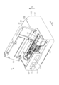
図5に示すように、記録装置11は、収容部23から記録部13に向けて延びる搬送経路26を備える。搬送経路26は、媒体99が搬送される経路である。収容部23に収容される媒体99は、搬送経路26を通じて記録部13に搬送される。図5において、筐体12内に1点鎖線で示される経路が搬送経路26である。
As shown in FIG. 5 , the
搬送経路26は、収容部23から記録部13に向かう過程で媒体99の姿勢を上下に反転させるように湾曲する湾曲部分26Aを有する。湾曲部分26Aは、搬送経路26において、湾曲しながら延びる部分である。そのため、搬送経路26は、湾曲部分26Aにおいて媒体99を湾曲させる。
The conveying
記録装置11は、片面に記録された媒体99を搬送経路26に戻すための反転経路27を備えてもよい。本実施形態においては、図5において、筐体12内に破線で示される経路が反転経路27である。反転経路27は、搬送経路26の下流部分と搬送経路26の上流部分とに繋がる。反転経路27と搬送経路26との接続点は、搬送経路26において、湾曲部分26Aを挟むように位置する。
The
例えば、媒体99の両面に記録する場合に、媒体99は反転経路27を搬送される。片面に記録された媒体99は、搬送経路26を通常とは逆向きに搬送されることによって、反転経路27に案内される。反転経路27に案内された媒体99は、反転経路27を搬送されることによって、搬送経路26に戻される。搬送経路26に戻された媒体99は、再び搬送経路26を記録部13に向けて搬送される。このとき、媒体99は、記録された面とは反対の面が記録部13と対向する姿勢となる。このようにして、記録装置11は、媒体99の両面に記録する。
For example, when recording on both sides of the medium 99 , the medium 99 is conveyed through the reversing
搬送経路26を搬送される媒体99は、前面12Aから後面12Cに向かう方向、及び後面12Cから前面12Aに向かう方向に進行する。収容部23に収容される媒体99は、記録される場合に、搬送経路26に沿って、前面12Aから後面12Cに向けて進行する。媒体99は、反転経路27を通過した後、搬送経路26に沿って、後面12Cから前面12Aに向けて進行する。
A medium 99 conveyed along the conveying
記録装置11は、搬送経路26に沿って媒体99を搬送する搬送部28を備える。搬送部28は、収容部23から記録部13に向けて媒体99を搬送する。搬送部28は、例えば複数のローラーで構成される。搬送部28を構成する複数のローラーは、例えば、搬送経路26に沿って配置される。
The
搬送部28は、収容部23から記録部13に向かう過程において媒体99の姿勢を上下に反転させる反転ローラー28Aを有してもよい。反転ローラー28Aは、媒体99を湾曲させながら搬送する。これにより、媒体99の姿勢が、収容部23から記録部13に向かう過程で、上下に反転する。本実施形態の反転ローラー28Aは、搬送経路26の湾曲部分26Aにその外周面が沿うように位置する。すなわち、本実施形態において、湾曲部分26Aは、搬送経路26において反転ローラー28Aの外周面に沿って延びる部分である。
The conveying
本実施形態の搬送部28は、搬送経路26を搬送される媒体99のスキューを除去するための搬送ローラー28Bを有する。スキューとは、搬送される媒体99の傾きのことである。回転が停止した状態の搬送ローラー28Bに媒体99が突き当てられることによって、媒体99のスキューが除去される。本実施形態においては、反転ローラー28Aによって搬送された媒体99が、搬送ローラー28Bに突き当てられる。
The
本実施形態の搬送ローラー28Bは、奥行方向F1において、記録部13と並ぶように位置する。すなわち、本実施形態の搬送ローラー28Bは、記録部13の後方に位置する。本実施形態の搬送ローラー28Bは、搬送部28を構成する複数のローラーのうち、搬送経路26において最も下流に位置するローラーである。
The
本実施形態の搬送部28は、収容部23から媒体99を取り出すピックアップローラー28Cを有する。ピックアップローラー28Cは、収容部23に収容される複数の媒体99のうち、最も上に位置する1枚目の媒体99に接触する。ピックアップローラー28Cは、媒体99に接触する状態で回転することによって、媒体99を収容部23から取り出す。
The
本実施形態のピックアップローラー28Cは、反転ローラー28Aの下方に位置する。本実施形態のピックアップローラー28Cは、反転ローラー28Aに向けて媒体99を搬送する。本実施形態のピックアップローラー28Cは、搬送部28を構成する複数のローラーのうち、搬送経路26において最も上流に位置するローラーである。
The
記録装置11は、収容部23に収容される媒体99を分離させる分離部29を備えてもよい。分離部29は、例えば収容部23から媒体99が複数枚取り出された場合に、その複数の媒体99を1枚ずつに分離させる。本実施形態において、分離部29は、ピックアップローラー28Cによって複数枚取り出された媒体99を1枚ずつに分離させる。
The
本実施形態の分離部29は、搬送経路26の一部を形成する。分離部29は、例えば、その表面に細かい突起が複数形成された部材である。収容部23から取り出された媒体99は、その先端が分離部29の表面に接触することによって、反転ローラー28Aに向けて搬送される。このとき、収容部23から複数枚の媒体99が取り出された場合には、ピックアップローラー28Cと接触しない2枚目以降の媒体99が、分離部29の表面に形成された突起に引っ掛かる。これにより、ピックアップローラー28Cと接触する1枚目の媒体99のみが反転ローラー28Aに向けて搬送される。このようにして、媒体99が1枚ずつに分離される。
The separating
記録装置11は、原稿91を読み取る読取部31と、読取部31に向けて原稿91を送る供給部32とを備える。読取ユニット21は、例えば、読取部31と供給部32とを含む。本実施形態において、記録装置11は、読取部31によって読み取られた原稿91を排出する排出部33と、原稿91が通過する供給部32から排出部33までの供給経路34とを備える。そのため、本実施形態の読取ユニット21は、さらに、案内部材22と、排出部33と、供給経路34とを含む。
The
読取部31は、記録部13よりも上方に位置する。読取部31は、例えばイメージセンサーモジュールである。そのため、読取部31は、例えば、原稿91に向けて光を発する発光素子、原稿91によって反射された光を受ける受光素子などを有する。読取部31は、筐体12に対して固定される。本実施形態の読取部31は、供給経路34を通過する原稿91を読み取る。本実施形態の読取部31は、原稿91を下方から読み取る。そのため、本実施形態の読取部31は、メンテナンスカバー19上に置かれた原稿91の下面を読み取る。
The
供給経路34及び搬送経路26は、筐体12の幅方向と直交する方向に形成される。本実施形態の供給経路34は、奥行方向F1に延びる。本実施形態の搬送経路26は、奥行方向F1と、その反対方向に延びる。筐体12の幅方向とは、奥行方向F1と異なる方向である。筐体12の幅方向は、記録装置11の幅を示す指標となる。
The
本実施形態の供給部32は、奥行方向F1へ原稿91を送る。供給部32は、例えばローラー対である。
本実施形態の排出部33は、奥行方向F1へ原稿91を送る。排出部33は、案内部材22に向けて原稿91を排出する。排出部33は、例えばローラー対である。供給部32及び排出部33は、供給経路34に沿って原稿91を送る。
The
The
供給経路34は、読取部31に向けて原稿91を供給するための供給開口35と、読取後の原稿91を排出するための排出開口36とを有する。原稿91は、供給開口35を通過することによって、読取ユニット21外から読取ユニット21内に送られる。原稿91は、排出開口36を通過することによって、読取ユニット21内から読取ユニット21外に送られる。原稿91は、読取ユニット21にセットされる場合、その先端が供給開口35に差し込まれた状態でメンテナンスカバー19上に置かれる。
The
読取部31、供給部32及び排出部33は、供給経路34沿いに並んで配置される。奥行方向F1において、供給部32、読取部31、排出部33は、この順で供給経路34沿いに並んで配置される。尚、供給部32は供給ローラー、排出部33は排出ローラーである。
The
案内部材22は、閉じることによって、供給開口35と排出開口36とを覆う。これにより、案内部材22は、読取ユニット21内に塵埃が進入することを抑制する。
本実施形態の記録装置11は、読取ユニット21を支持するユニットフレーム38を備える。読取ユニット21は、ユニットフレーム38に取り付けられることによって、筐体12に固定される。
The
The
本実施形態のユニットフレーム38は、湾曲部分26Aを形成する。ユニットフレーム38は、例えば、反転ローラー28Aを覆うように位置することによって、湾曲部分26Aを形成する。このとき、ユニットフレーム38は、湾曲部分26Aの少なくとも一部を形成していればよい。ユニットフレーム38は、読取ユニット21を支持する部材と、湾曲部分26Aを形成する部材とを兼ねる。そのため、本実施形態においては、湾曲部分26Aを形成する部材を別途備える構成と比べて、記録装置11を構成する部品点数の増加を抑制できる。
The
読取部31は、奥行方向F1において、記録部13よりも後方に位置する。この場合、読取部31が記録部13と上下で重ならない。すなわち、筐体12を上方から見た場合に、読取部31は、記録部13と重ならないようにずれて配置される。
The
読取部31が記録部13と上下で重なる構成、すなわち、筐体12を上方から見た場合に読取部31が記録部13と重なるように配置される構成においては、記録装置11の高さが高くなりやすい。この点、読取部31が奥行方向F1において記録部13よりも後方に位置することによって、筐体12を上方から見た場合に読取部31が記録部13と重なる構成と比べて、記録装置11の高さを抑えることができる。
In a configuration in which the
読取部31は、奥行方向F1において、湾曲部分26Aと搬送ローラー28Bとの間に位置してもよい。すなわち、筐体12を上方から見た場合に、読取部31は、湾曲部分26Aと搬送ローラー28Bとに重ならないようにずれて配置されてもよい。この場合、筐体12を上方から見た場合に読取部31が湾曲部分26Aと重なる構成、及び、筐体12を上方から見た場合に読取部31が搬送ローラー28Bと重なる構成と比べて、記録装置11の高さを抑えることができる。
The
分離部29は、奥行方向F1において、読取部31よりも後方に位置してもよい。すなわち、筐体12を上方から見た場合に、分離部29は、読取部31と重ならないようにずれて配置されてもよい。この場合、筐体12を上方から見た場合に分離部29が読取部31と重なる構成と比べて、記録装置11の高さを抑えることができる。
分離部29は、奥行方向F1において、案内部材22が閉じた状態の読取ユニット21よりも後方に位置してもよい。すなわち、筐体12を上方から見た場合に、分離部29は、案内部材22が閉じた状態の読取ユニット21と重ならないようにずれて配置されてもよい。この場合、記録装置11の高さをより抑えることができる。
The
キャリッジ14は、高さ方向F2において読取部31と重なっていてもよい。すなわち、筐体12を前方、又は後方から見た場合に、キャリッジ14は、読取部31と重なるように配置されていてもよい。このとき、キャリッジ14の少なくとも一部分が読取部31と重なっていればよい。本実施形態においては、キャリッジ14の上端部分が、読取部31の下端部分と高さ方向F2において重なる。
The
高さ方向F2とは、記録装置11の高さを示す指標となる方向である。本実施形態において、記録装置11は、水平面に設置される。この場合、高さ方向F2は、鉛直方向と反対の方向となる。
The height direction F2 is a direction that serves as an index indicating the height of the
キャリッジ14が読取部31と高さ方向F2においてずれて配置される場合、記録装置11の高さが高くなりやすい。この点、キャリッジ14が読取部31と高さ方向F2において重なることによって、キャリッジ14が読取部31と高さ方向F2において重ならない構成と比べて、記録装置11の高さを抑えることができる。例えば、キャリッジ14が読取部31よりも下方又は上方に位置する場合と比べて、記録装置11の高さを抑えることができる。
If the
メンテナンスカバー19は、高さ方向F2において読取部31と重なっていてもよい。すなわち、筐体12を前方、又は後方から見た場合に、メンテナンスカバー19は、読取部31と重なるように配置されていてもよい。このとき、メンテナンスカバー19の少なくとも一部分が読取部31と重なっていればよい。
The
メンテナンスカバー19が読取部31と高さ方向F2においてずれて配置される場合、記録装置11の高さが高くなりやすい。この点、メンテナンスカバー19が読取部31と高さ方向F2において重なることによって、メンテナンスカバー19が読取部31と高さ方向F2において重ならない構成と比べて、記録装置11の高さを抑えることができる。例えば、メンテナンスカバー19が読取部31よりも下方又は上方に位置する場合と比べて、記録装置11の高さを抑えることができる。
If the
次に、上記実施形態の作用及び効果について説明する。
(1)読取部31は、奥行方向F1において、記録部13よりも後方に位置する。そのため、読取部31は、記録部13と上下で重ならない。すなわち、筐体12を上方から見た場合に、読取部31は、記録部13と重ならないようにずれて配置される。これにより、筐体12の上方から見た場合に読取部31が記録部13と重なる構成と比べて、記録装置11の高さを抑えることができる。
Next, the operation and effects of the above embodiment will be described.
(1) The
(2)供給部32、読取部31、排出部33は、供給経路34沿いに並んで配置される。これにより、原稿91をスムーズに読み取ることができる。
(3)読取部31は、奥行方向F1において、湾曲部分26Aと搬送ローラー28Bとの間に位置する。これにより、例えば、筐体12を上方から見た場合に読取部31が湾曲部分26Aと重なる構成、及び、筐体12を上方から見た場合に読取部31が搬送ローラー28Bと重なる構成と比べて、記録装置11の高さを抑えることができる。
(2) The
(3) The
(4)分離部29は、奥行方向F1において、読取部31よりも後方に位置する。これにより、例えば、筐体12を上方から見た場合に分離部29が読取部31と重なる構成と比べて、記録装置11の高さを抑えることができる。
(4)
(5)キャリッジ14は、高さ方向F2において、読取部31と重なる。これにより、キャリッジ14が読取部31と高さ方向F2において重ならない構成、例えばキャリッジ14が読取部31よりも下方又は上方に位置する構成と比べて、記録装置11の高さを抑えることができる。
(5) The
(6)メンテナンスカバー19は、高さ方向F2において、読取部31と重なる。これにより、メンテナンスカバー19が読取部31と高さ方向F2において重ならない構成、例えばメンテナンスカバー19が読取部31よりも下方又は上方に位置する構成と比べて、記録装置11の高さを抑えることができる。
(6) The
(7)読取ユニット21を支持するユニットフレーム38は、湾曲部分26Aを形成する。ユニットフレーム38が湾曲部分26Aを形成するため、湾曲部分26Aを形成する部材を別途備える構成と比べて、記録装置11を構成する部品点数の増加を抑制できる。
(7) A
本実施形態は、以下のように変更して実施することができる。本実施形態及び以下の変更例は、技術的に矛盾しない範囲で互いに組み合わせて実施することができる。
・筐体の上面12Bが読取前の原稿91が置かれるトレイとして機能してもよい。
This embodiment can be implemented with the following modifications. This embodiment and the following modified examples can be implemented in combination with each other within a technically consistent range.
- The
・読取部31が、供給経路34の下方に設けられているが、上方に設けられてもよく、また上方、下方の両方に設けられてもよい。
・分離部29は、ピックアップローラー28Cによって取り出された媒体99を挟み込むローラー対であってもよい。例えば、ローラー対を構成する2つのローラーの回転抵抗がそれぞれ異なることによって、媒体99を分離できる。
- Although the
- The
・記録装置11は、収容部23とは別に、筐体12の後面12Cから媒体99を供給可能に構成されてもよい。
・媒体99は、金属フィルム、プラスチックフィルム、布帛などでもよい。
- The
- The medium 99 may be a metal film, a plastic film, a fabric, or the like.
・記録部13は、媒体99に液体を吐出することによって記録する構成に限らず、媒体99に熱を加えることによって記録する構成でもよいし、媒体99に打刻することによって記録する構成でもよい。
The
・記録部13が吐出する液体はインクに限らず、例えば機能材料の粒子が液体に分散又は混合されてなる液状体などでもよい。例えば、記録部13が液晶ディスプレイ、エレクトロルミネッセンスディスプレイ及び面発光ディスプレイの製造などに用いられる電極材または画素材料などの材料を分散または溶解のかたちで含む液状体を吐出してもよい。
The liquid ejected by the
以下に、上述した実施形態及び変更例から把握される技術的思想及びその作用効果を記載する。
(A)記録装置は、筐体と、前記筐体に収容され、媒体に記録する記録部と、前記筐体に対して着脱可能に構成され、前記媒体を収容する収容部と、前記収容部から前記記録部に向けて延び、前記媒体が搬送される搬送経路と、前記搬送経路に沿って前記媒体を搬送する搬送部と、前記記録部よりも上方に位置し、原稿を読み取る読取部と、前記読取部に向けて前記原稿を送る供給部と、前記読取部に読み取られた前記原稿を排出する排出部と、前記原稿が通過する前記供給部から前記排出部までの供給経路と、を備え、前記筐体は、前記記録部によって記録された前記媒体が排出される排出口を前記筐体の前面に有し、前記供給経路及び前記搬送経路は、前記筐体の幅方向と直交する方向に形成され、前記収容部は、前記筐体の前記前面から着脱可能であり、前記搬送経路は、前記収容部から前記記録部に向かう過程で前記媒体の姿勢を上下に反転させるように湾曲する湾曲部分を有し、前記読取部は、前記筐体の前記前面から前記筐体の後面に向かう奥行方向において、前記記録部よりも後方に位置する。
The technical ideas and effects obtained from the above-described embodiments and modifications will be described below.
(A) A recording apparatus includes a housing, a recording unit that is housed in the housing and records on a medium, a storage unit that is detachable from the housing and stores the medium, and the storage unit. a conveying path for conveying the medium, a conveying section for conveying the medium along the conveying path, and a reading section positioned above the recording section for reading an original document. a supply section for feeding the document toward the reading section; a discharge section for discharging the document read by the reading section; and a supply path through which the document passes from the supply section to the discharge section. The housing has a discharge port on the front surface of the housing through which the medium recorded by the recording unit is discharged, and the supply path and the transport path are orthogonal to the width direction of the housing. The storage section is detachable from the front surface of the housing, and the transport path is curved so as to invert the posture of the medium in the process of moving from the storage section to the recording section. The reading unit is located behind the recording unit in the depth direction from the front surface of the housing to the rear surface of the housing.
この構成によれば、読取部は、記録部と上下で重ならない。すなわち、筐体を上方から見た場合に、読取部は、記録部と重ならないようにずれて配置される。これにより、筐体の上方から見た場合に読取部が記録部と重なる構成と比べて、記録装置の高さを抑えることができる。 According to this configuration, the reading section does not overlap the recording section. In other words, when the housing is viewed from above, the reading section is displaced from the recording section so as not to overlap. This makes it possible to reduce the height of the recording apparatus compared to a configuration in which the reading section overlaps the recording section when viewed from above the housing.
(B)上記記録装置において、前記供給部、前記読取部、前記排出部は、前記供給経路沿いに並んで配置されてもよい。
この構成によれば、原稿をスムーズに読み取ることができる。
(B) In the above recording apparatus, the supply section, the reading section, and the discharge section may be arranged side by side along the supply route.
According to this configuration, the document can be read smoothly.
(C)上記記録装置において、前記搬送部は、前記搬送経路を搬送される前記媒体のスキューを除去するための搬送ローラーを有し、前記読取部は、前記奥行方向において、前記湾曲部分と前記搬送ローラーとの間に位置してもよい。 (C) In the above-described recording apparatus, the transport section has a transport roller for removing skew of the medium transported on the transport path, and the reading section is arranged in the depth direction between the curved portion and the It may be positioned between the transport rollers.
この構成によれば、例えば、筐体を上方から見た場合に読取部が湾曲部分と重なる構成、及び、筐体を上方から見た場合に読取部が搬送ローラーと重なる構成と比べて、記録装置の高さを抑えることができる。 According to this configuration, for example, when the housing is viewed from above, the reading section overlaps the curved portion, and when the housing is viewed from above, the reading section overlaps the transport roller. The height of the device can be suppressed.
(D)上記記録装置は、前記収容部に収容される前記媒体を分離させる分離部を備え、前記分離部は、前記奥行方向において、前記読取部よりも後方に位置してもよい。
この構成によれば、例えば、筐体を上方から見た場合に分離部が読取部と重なる構成と比べて、記録装置の高さを抑えることができる。
(D) The recording apparatus may include a separating section that separates the medium accommodated in the accommodating section, and the separating section may be positioned behind the reading section in the depth direction.
According to this configuration, the height of the recording apparatus can be reduced compared to, for example, a configuration in which the separation section overlaps the reading section when the housing is viewed from above.
(E)上記記録装置は、前記記録部を搭載し、前記媒体に対して走査するキャリッジを備え、前記キャリッジは、高さ方向において、前記読取部と重なってもよい。
この構成によれば、キャリッジが読取部と高さ方向において重ならない構成、例えばキャリッジが読取部よりも下方又は上方に位置する構成と比べて、記録装置の高さを抑えることができる。
(E) The recording apparatus may include a carriage on which the recording unit is mounted and which scans the medium, and the carriage may overlap the reading unit in a height direction.
According to this configuration, the height of the recording apparatus can be reduced compared to a configuration in which the carriage does not overlap the reading unit in the height direction, for example, a configuration in which the carriage is positioned below or above the reading unit.
(F)上記記録装置は、前記筐体に対して開くことによって、前記筐体内を露出させるメンテナンスカバーを備え、前記メンテナンスカバーは、高さ方向において、前記読取部と重なってもよい。 (F) The recording apparatus may include a maintenance cover that exposes the interior of the housing by opening the housing, and the maintenance cover may overlap the reading section in the height direction.
この構成によれば、メンテナンスカバーが読取部と高さ方向において重ならない構成、例えばメンテナンスカバーが読取部よりも下方又は上方に位置する構成と比べて、記録装置の高さを抑えることができる。 With this configuration, the height of the recording apparatus can be reduced compared to a configuration in which the maintenance cover does not overlap the reading unit in the height direction, for example, a configuration in which the maintenance cover is positioned below or above the reading unit.
(G)上記記録装置は、前記読取部と、前記供給部と、を含む読取ユニットと、前記読取ユニットを支持するユニットフレームと、を備え、前記ユニットフレームは、前記湾曲部分を形成してもよい。 (G) The recording apparatus includes a reading unit including the reading section and the feeding section, and a unit frame that supports the reading unit, and the unit frame may form the curved portion. good.
この構成によれば、ユニットフレームが湾曲部分を形成するため、湾曲部分を形成する部材を別途備える構成と比べて、記録装置を構成する部品点数の増加を抑制できる。 According to this configuration, since the unit frame forms the curved portion, it is possible to suppress an increase in the number of parts constituting the recording apparatus, compared to a configuration in which a separate member for forming the curved portion is provided.
11…記録装置、12…筐体、12A…前面、12B…上面、12C…後面、13…記録部、14…キャリッジ、15…操作部、16…表示画面、17…操作ボタン、18…排出カバー、19…メンテナンスカバー、21…読取ユニット、22…案内部材、23…収容部、24…排出口、26…搬送経路、26A…湾曲部分、27…反転経路、28…搬送部、28A…反転ローラー、28B…搬送ローラー、28C…ピックアップローラー、29…分離部、31…読取部、32…供給部、33…排出部、34…供給経路、35…供給開口、36…排出開口、38…ユニットフレーム、91…原稿、99…媒体、F1…奥行方向、F2…高さ方向。
DESCRIPTION OF
Claims (8)
前記筐体に収容され、媒体に記録する記録部と、
前記媒体を収容する収容部と、
前記収容部から前記記録部に向けて延び、前記媒体が搬送される搬送経路と、
前記搬送経路に沿って前記媒体を搬送する搬送部と、
前記記録部よりも上方に位置し、原稿を読み取る読取部と、
前記読取部に向けて前記原稿を送る供給部と、
前記読取部に読み取られた前記原稿を排出する排出部と、
前記原稿が通過する前記供給部から前記排出部までの供給経路と、を備え、
前記筐体は、前記記録部によって記録された前記媒体が排出される排出口を前記筐体の前面に有し、
前記供給経路及び前記搬送経路は、それぞれ合流することなく独立した経路であり、前記筐体の幅方向と直交する方向に形成され、
前記供給経路は、前記搬送経路よりも上方に位置し、
前記搬送経路は、前記収容部から前記記録部に向かう過程で前記媒体の姿勢を上下に反転させるように湾曲する湾曲部分を有し、
前記読取部は、前記筐体の前記前面から前記筐体の後面に向かう奥行方向において、前記記録部よりも後方に位置することを特徴とする記録装置。 a housing;
a recording unit that is housed in the housing and records on a medium;
a storage unit that stores the medium;
a transport path that extends from the storage unit toward the recording unit and transports the medium;
a transport unit that transports the medium along the transport path;
a reading unit positioned above the recording unit for reading a document;
a supply unit that feeds the document toward the reading unit;
a discharge unit for discharging the document read by the reading unit;
a supply path through which the document passes from the supply unit to the discharge unit;
the housing has a discharge port on the front surface of the housing through which the medium recorded by the recording unit is discharged;
The supply route and the transport route are independent routes without merging, and are formed in a direction perpendicular to the width direction of the housing,
The supply route is positioned above the transport route,
the transport path has a curved portion that curves so as to reverse the posture of the medium in the process of moving from the storage unit to the recording unit;
The recording apparatus according to claim 1, wherein the reading section is positioned behind the recording section in a depth direction from the front surface of the housing to the rear surface of the housing.
前記読取部は、前記奥行方向において、前記湾曲部分と前記搬送ローラーとの間に位置することを特徴とする請求項1又は請求項2に記載の記録装置。 The transport unit has a transport roller,
3. The recording apparatus according to claim 1, wherein the reading section is positioned between the curved portion and the transport roller in the depth direction.
前記分離部は、前記奥行方向において、前記読取部よりも後方に位置することを特徴とする請求項1から請求項3の何れか一項に記載の記録装置。 a separation unit that separates the medium stored in the storage unit;
4. The recording apparatus according to any one of claims 1 to 3, wherein the separating section is positioned behind the reading section in the depth direction.
前記キャリッジは、高さ方向において、前記読取部と重なることを特徴とする請求項1から請求項4の何れか一項に記載の記録装置。 A carriage on which the recording unit is mounted and which scans the medium,
5. The recording apparatus according to claim 1, wherein the carriage overlaps the reading section in the height direction.
前記メンテナンスカバーは、高さ方向において、前記読取部と重なることを特徴とする請求項1から請求項5の何れか一項に記載の記録装置。 a maintenance cover that exposes the inside of the housing by opening the housing;
6. The recording apparatus according to claim 1, wherein the maintenance cover overlaps the reading section in the height direction.
前記読取ユニットを支持するユニットフレームと、を備え、
前記ユニットフレームは、前記湾曲部分を形成することを特徴とする請求項1から請求項6の何れか一項に記載の記録装置。 a reading unit including the reading unit and the supply unit;
a unit frame that supports the reading unit;
7. The recording apparatus according to claim 1, wherein said unit frame forms said curved portion.
前記供給部、前記読取部、前記排出部は、前記奥行方向において、前記供給部、前記読取部、前記排出部の順に前記供給経路沿いに上下で重ならずに並んで配置されることを特徴とする請求項1から請求項7の何れか一項に記載の記録装置。 The supply unit, the reading unit, and the discharge unit are arranged side by side along the supply path in the order of the supply unit, the reading unit, and the discharge unit in the depth direction without overlapping each other. 8. The recording apparatus according to any one of claims 1 to 7.
Priority Applications (4)
| Application Number | Priority Date | Filing Date | Title |
|---|---|---|---|
| JP2019095327A JP7247746B2 (en) | 2019-05-21 | 2019-05-21 | recording device |
| US16/876,277 US11707940B2 (en) | 2019-05-21 | 2020-05-18 | Recording apparatus |
| CN202010430244.9A CN111976290B (en) | 2019-05-21 | 2020-05-20 | Recording apparatus |
| US18/331,506 US20230311549A1 (en) | 2019-05-21 | 2023-06-08 | Recording apparatus |
Applications Claiming Priority (1)
| Application Number | Priority Date | Filing Date | Title |
|---|---|---|---|
| JP2019095327A JP7247746B2 (en) | 2019-05-21 | 2019-05-21 | recording device |
Publications (3)
| Publication Number | Publication Date |
|---|---|
| JP2020191526A JP2020191526A (en) | 2020-11-26 |
| JP2020191526A5 JP2020191526A5 (en) | 2022-04-14 |
| JP7247746B2 true JP7247746B2 (en) | 2023-03-29 |
Family
ID=73441811
Family Applications (1)
| Application Number | Title | Priority Date | Filing Date |
|---|---|---|---|
| JP2019095327A Active JP7247746B2 (en) | 2019-05-21 | 2019-05-21 | recording device |
Country Status (3)
| Country | Link |
|---|---|
| US (2) | US11707940B2 (en) |
| JP (1) | JP7247746B2 (en) |
| CN (1) | CN111976290B (en) |
Families Citing this family (2)
| Publication number | Priority date | Publication date | Assignee | Title |
|---|---|---|---|---|
| JP7188263B2 (en) * | 2019-04-24 | 2022-12-13 | セイコーエプソン株式会社 | recording device |
| JP7251309B2 (en) * | 2019-05-21 | 2023-04-04 | セイコーエプソン株式会社 | recording device |
Citations (3)
| Publication number | Priority date | Publication date | Assignee | Title |
|---|---|---|---|---|
| JP2001109210A (en) | 1992-12-28 | 2001-04-20 | Canon Inc | Image forming device |
| JP2015211415A (en) | 2014-04-30 | 2015-11-24 | セイコーエプソン株式会社 | Multi-function peripheral |
| JP2019059590A (en) | 2017-09-27 | 2019-04-18 | セイコーエプソン株式会社 | Recording device |
Family Cites Families (27)
| Publication number | Priority date | Publication date | Assignee | Title |
|---|---|---|---|---|
| JP3543511B2 (en) * | 1996-10-17 | 2004-07-14 | 村田機械株式会社 | Image recording device |
| CN1257640C (en) * | 2001-12-27 | 2006-05-24 | 尼司卡股份有限公司 | Image fetch device |
| AU2003219553A1 (en) * | 2002-03-28 | 2003-10-13 | Brother Kogyo Kabushiki Kaisha | Printing device |
| JP4635426B2 (en) * | 2003-10-22 | 2011-02-23 | ブラザー工業株式会社 | Image forming apparatus |
| US7712891B2 (en) * | 2003-12-26 | 2010-05-11 | Brother Kogyo Kabushiki Kaisha | Image-forming device |
| JP4386173B2 (en) * | 2003-12-26 | 2009-12-16 | ブラザー工業株式会社 | Image forming apparatus |
| JP2005309014A (en) * | 2004-04-20 | 2005-11-04 | Matsushita Electric Ind Co Ltd | Image forming apparatus |
| JP2006103954A (en) * | 2004-10-08 | 2006-04-20 | Brother Ind Ltd | Image recording device |
| CN100503401C (en) * | 2005-02-03 | 2009-06-24 | 光宝科技股份有限公司 | Paper feeding device and its paper turning method |
| JP2007036605A (en) * | 2005-07-26 | 2007-02-08 | Brother Ind Ltd | Multifunction device |
| US8228511B2 (en) * | 2007-08-31 | 2012-07-24 | Kabushiki Kaisha Toshiba | Image forming apparatus |
| JP5640626B2 (en) | 2010-10-08 | 2014-12-17 | セイコーエプソン株式会社 | Compound machine |
| JP5948909B2 (en) * | 2012-01-31 | 2016-07-06 | ブラザー工業株式会社 | Image forming apparatus |
| EP2657776B1 (en) * | 2012-04-25 | 2019-05-01 | Brother Kogyo Kabushiki Kaisha | Image forming apparatus |
| JP2014096717A (en) * | 2012-11-09 | 2014-05-22 | Brother Ind Ltd | Image forming apparatus |
| JP6216123B2 (en) | 2013-01-30 | 2017-10-18 | ブラザー工業株式会社 | Image forming apparatus |
| JP6036488B2 (en) * | 2013-03-29 | 2016-11-30 | ブラザー工業株式会社 | Sheet conveying apparatus and image reading apparatus |
| US9427982B2 (en) * | 2013-03-29 | 2016-08-30 | Seiko Epson Corporation | Recording apparatus |
| US9387694B2 (en) * | 2013-06-17 | 2016-07-12 | Seiko Epson Corporation | Recording apparatus |
| JP6330275B2 (en) * | 2013-08-29 | 2018-05-30 | セイコーエプソン株式会社 | Recording device |
| US9118830B2 (en) * | 2013-09-17 | 2015-08-25 | Seiko Epson Corporation | Recording apparatus |
| JP6094466B2 (en) | 2013-12-20 | 2017-03-15 | ブラザー工業株式会社 | Compound machine |
| JP6394039B2 (en) * | 2014-04-14 | 2018-09-26 | セイコーエプソン株式会社 | Recording device |
| CN105979111B (en) * | 2015-03-12 | 2019-09-24 | 精工爱普生株式会社 | Image read-out and image read system |
| JP6730657B2 (en) * | 2016-02-01 | 2020-07-29 | セイコーエプソン株式会社 | Recording device |
| JP2018174519A (en) | 2017-03-31 | 2018-11-08 | キヤノン株式会社 | Image forming apparatus |
| US10603926B2 (en) | 2017-03-31 | 2020-03-31 | Canon Kabushiki Kaisha | Image forming apparatus |
-
2019
- 2019-05-21 JP JP2019095327A patent/JP7247746B2/en active Active
-
2020
- 2020-05-18 US US16/876,277 patent/US11707940B2/en active Active
- 2020-05-20 CN CN202010430244.9A patent/CN111976290B/en active Active
-
2023
- 2023-06-08 US US18/331,506 patent/US20230311549A1/en active Pending
Patent Citations (3)
| Publication number | Priority date | Publication date | Assignee | Title |
|---|---|---|---|---|
| JP2001109210A (en) | 1992-12-28 | 2001-04-20 | Canon Inc | Image forming device |
| JP2015211415A (en) | 2014-04-30 | 2015-11-24 | セイコーエプソン株式会社 | Multi-function peripheral |
| JP2019059590A (en) | 2017-09-27 | 2019-04-18 | セイコーエプソン株式会社 | Recording device |
Also Published As
| Publication number | Publication date |
|---|---|
| CN111976290B (en) | 2022-08-30 |
| JP2020191526A (en) | 2020-11-26 |
| US11707940B2 (en) | 2023-07-25 |
| CN111976290A (en) | 2020-11-24 |
| US20230311549A1 (en) | 2023-10-05 |
| US20200369057A1 (en) | 2020-11-26 |
Similar Documents
| Publication | Publication Date | Title |
|---|---|---|
| US7806524B2 (en) | Platen for marginless image recording and image recording apparatus with such a platen mounted therein | |
| JP4289357B2 (en) | Image forming apparatus and paper feed cassette | |
| JP2007223735A (en) | Image recording device | |
| US20230311549A1 (en) | Recording apparatus | |
| CN104228356A (en) | Recording apparatus | |
| JP4678480B2 (en) | Image recording apparatus and paper feed tray applied thereto | |
| JP2007091429A (en) | Paper feeder | |
| JP2005187166A (en) | Conveying device for sheet-like member to be conveyed, dust removing member used therefor, and information processing device having conveying device and dust removing member | |
| JP2008156101A (en) | Image recording device | |
| JP5545058B2 (en) | Image recording device | |
| JP5899997B2 (en) | Recording device | |
| US10759191B2 (en) | Printing apparatus with curved feed path | |
| JP7251309B2 (en) | recording device | |
| JP2023050317A (en) | Image recording device | |
| JP2014015325A (en) | Feeding unit and recording device | |
| JP6447664B2 (en) | Image recording device | |
| JP7099130B2 (en) | Printing equipment | |
| JP2013112459A (en) | Image recorder | |
| JP5970707B2 (en) | Recording device | |
| JP6156525B2 (en) | Image recording device | |
| JP2023050315A (en) | Image recording device | |
| JP5874779B2 (en) | Image recording device | |
| JP2019034859A (en) | Image recording device | |
| JP2023050319A (en) | Image recording device | |
| JP2012176581A (en) | Image forming apparatus |
Legal Events
| Date | Code | Title | Description |
|---|---|---|---|
| A521 | Request for written amendment filed |
Free format text: JAPANESE INTERMEDIATE CODE: A523 Effective date: 20220406 |
|
| A621 | Written request for application examination |
Free format text: JAPANESE INTERMEDIATE CODE: A621 Effective date: 20220406 |
|
| A977 | Report on retrieval |
Free format text: JAPANESE INTERMEDIATE CODE: A971007 Effective date: 20221208 |
|
| A131 | Notification of reasons for refusal |
Free format text: JAPANESE INTERMEDIATE CODE: A131 Effective date: 20221213 |
|
| A521 | Request for written amendment filed |
Free format text: JAPANESE INTERMEDIATE CODE: A523 Effective date: 20230203 |
|
| TRDD | Decision of grant or rejection written | ||
| A01 | Written decision to grant a patent or to grant a registration (utility model) |
Free format text: JAPANESE INTERMEDIATE CODE: A01 Effective date: 20230214 |
|
| A61 | First payment of annual fees (during grant procedure) |
Free format text: JAPANESE INTERMEDIATE CODE: A61 Effective date: 20230227 |
|
| R150 | Certificate of patent or registration of utility model |
Ref document number: 7247746 Country of ref document: JP Free format text: JAPANESE INTERMEDIATE CODE: R150 |