JP6330275B2 - Recording device - Google Patents
Recording device Download PDFInfo
- Publication number
- JP6330275B2 JP6330275B2 JP2013177661A JP2013177661A JP6330275B2 JP 6330275 B2 JP6330275 B2 JP 6330275B2 JP 2013177661 A JP2013177661 A JP 2013177661A JP 2013177661 A JP2013177661 A JP 2013177661A JP 6330275 B2 JP6330275 B2 JP 6330275B2
- Authority
- JP
- Japan
- Prior art keywords
- holding
- holding body
- housing
- recording apparatus
- liquid
- Prior art date
- Legal status (The legal status is an assumption and is not a legal conclusion. Google has not performed a legal analysis and makes no representation as to the accuracy of the status listed.)
- Active
Links
Images


Classifications
-
- B—PERFORMING OPERATIONS; TRANSPORTING
- B41—PRINTING; LINING MACHINES; TYPEWRITERS; STAMPS
- B41J—TYPEWRITERS; SELECTIVE PRINTING MECHANISMS, i.e. MECHANISMS PRINTING OTHERWISE THAN FROM A FORME; CORRECTION OF TYPOGRAPHICAL ERRORS
- B41J2/00—Typewriters or selective printing mechanisms characterised by the printing or marking process for which they are designed
- B41J2/005—Typewriters or selective printing mechanisms characterised by the printing or marking process for which they are designed characterised by bringing liquid or particles selectively into contact with a printing material
- B41J2/01—Ink jet
- B41J2/17—Ink jet characterised by ink handling
- B41J2/175—Ink supply systems ; Circuit parts therefor
- B41J2/17503—Ink cartridges
- B41J2/1752—Mounting within the printer
-
- B—PERFORMING OPERATIONS; TRANSPORTING
- B41—PRINTING; LINING MACHINES; TYPEWRITERS; STAMPS
- B41J—TYPEWRITERS; SELECTIVE PRINTING MECHANISMS, i.e. MECHANISMS PRINTING OTHERWISE THAN FROM A FORME; CORRECTION OF TYPOGRAPHICAL ERRORS
- B41J2/00—Typewriters or selective printing mechanisms characterised by the printing or marking process for which they are designed
- B41J2/005—Typewriters or selective printing mechanisms characterised by the printing or marking process for which they are designed characterised by bringing liquid or particles selectively into contact with a printing material
- B41J2/01—Ink jet
- B41J2/17—Ink jet characterised by ink handling
- B41J2/175—Ink supply systems ; Circuit parts therefor
- B41J2/17503—Ink cartridges
- B41J2/17513—Inner structure
-
- B—PERFORMING OPERATIONS; TRANSPORTING
- B41—PRINTING; LINING MACHINES; TYPEWRITERS; STAMPS
- B41J—TYPEWRITERS; SELECTIVE PRINTING MECHANISMS, i.e. MECHANISMS PRINTING OTHERWISE THAN FROM A FORME; CORRECTION OF TYPOGRAPHICAL ERRORS
- B41J29/00—Details of, or accessories for, typewriters or selective printing mechanisms not otherwise provided for
- B41J29/02—Framework
-
- B—PERFORMING OPERATIONS; TRANSPORTING
- B41—PRINTING; LINING MACHINES; TYPEWRITERS; STAMPS
- B41J—TYPEWRITERS; SELECTIVE PRINTING MECHANISMS, i.e. MECHANISMS PRINTING OTHERWISE THAN FROM A FORME; CORRECTION OF TYPOGRAPHICAL ERRORS
- B41J29/00—Details of, or accessories for, typewriters or selective printing mechanisms not otherwise provided for
- B41J29/12—Guards, shields or dust excluders
- B41J29/13—Cases or covers
-
- B—PERFORMING OPERATIONS; TRANSPORTING
- B41—PRINTING; LINING MACHINES; TYPEWRITERS; STAMPS
- B41J—TYPEWRITERS; SELECTIVE PRINTING MECHANISMS, i.e. MECHANISMS PRINTING OTHERWISE THAN FROM A FORME; CORRECTION OF TYPOGRAPHICAL ERRORS
- B41J2/00—Typewriters or selective printing mechanisms characterised by the printing or marking process for which they are designed
- B41J2/005—Typewriters or selective printing mechanisms characterised by the printing or marking process for which they are designed characterised by bringing liquid or particles selectively into contact with a printing material
- B41J2/01—Ink jet
- B41J2/17—Ink jet characterised by ink handling
- B41J2/175—Ink supply systems ; Circuit parts therefor
- B41J2/17503—Ink cartridges
- B41J2/17513—Inner structure
- B41J2002/17516—Inner structure comprising a collapsible ink holder, e.g. a flexible bag
Landscapes
- Ink Jet (AREA)
- Impression-Transfer Materials And Handling Thereof (AREA)
Description
本発明は、記録装置に関する。 The present invention relates to a recording apparatus.
従来から、記録装置の一種として、記録ヘッドから用紙等に対してインクを噴射して印刷を行うインクジェット式プリンターが知られている。このようなインクジェット式プリンターにおいては、比較的大量の印刷を行う場合にプリンターヘッドへ連続的に安定してインクを供給するために、インクジェット式プリンターの本体装置とは別体に外部インク供給装置(液体供給装置)備え、プリンターヘッドにインクを供給する構成が提案されている(例えば、特許文献1参照)。 2. Description of the Related Art Conventionally, as a kind of recording apparatus, an ink jet printer that performs printing by ejecting ink from a recording head onto a sheet or the like is known. In such an ink jet printer, in order to continuously and stably supply ink to a printer head when a relatively large amount of printing is performed, an external ink supply device ( A configuration has been proposed in which a liquid supply device is provided and ink is supplied to a printer head (see, for example, Patent Document 1).
こうした液体供給装置には、大容量のインクパック(液体収容体)が備えられ、液体供給装置と本体装置内のプリンターヘッドとを連通するインク供給チューブによって、インクが供給される。 Such a liquid supply device includes a large-capacity ink pack (liquid container), and ink is supplied by an ink supply tube that communicates the liquid supply device and the printer head in the main body device.
しかしながら、インクジェット式プリンターの本体装置とは別体に、大容量のインクパックを保持する保持部を備える。そのため、インクジェット式プリンターが大型化するという課題がある。また、インクジェット式プリンターの本体装置に、大容量のインクパックを保持させる構成においても大容量のインクパックを本体装置の片側に配置するとバランスが悪く、本体装置が不安定になるという課題がある。 However, a holding unit that holds a large-capacity ink pack is provided separately from the main body of the ink jet printer. Therefore, there is a problem that the ink jet printer is increased in size. Further, even in a configuration in which a main body device of an ink jet printer holds a large capacity ink pack, if a large capacity ink pack is disposed on one side of the main body device, there is a problem that the balance is poor and the main body device becomes unstable.
本発明は、上述の課題の少なくとも一部を解決するためになされたものであり、以下の形態または適用例として実現することが可能である。 SUMMARY An advantage of some aspects of the invention is to solve at least a part of the problems described above, and the invention can be implemented as the following forms or application examples.
[適用例1]液体を記録媒体に噴射可能な記録ヘッドと、前記記録媒体を保持する記録媒体保持ユニットと、前記記録媒体を前記記録ヘッドに搬送する搬送ユニットと、前記記録ヘッドと前記搬送ユニットとを収容し、前記記録媒体保持ユニットが挿入される筐体と、前記筐体の外側面に形成され、前記記録媒体保持ユニットを挿入する挿入口と、前記液体を収容する液体収容体と、前記筐体の前記挿入口が形成された外側面に隣接する両側の外側面に配置され、前記液体収容体を保持する保持体と、前記液体収容体から前記筐体の内部に前記液体を供給する供給部と、を備え、両側の前記保持体の大きさが異なることを特徴とする記録装置。 Application Example 1 A recording head capable of ejecting liquid onto a recording medium, a recording medium holding unit that holds the recording medium, a conveying unit that conveys the recording medium to the recording head, the recording head, and the conveying unit A housing into which the recording medium holding unit is inserted, an insertion port that is formed on the outer surface of the housing and into which the recording medium holding unit is inserted, and a liquid container that contains the liquid; A holding body that holds the liquid container and is disposed on both outer surfaces adjacent to the outer surface of the housing where the insertion port is formed, and the liquid is supplied from the liquid container to the inside of the housing. And a supply unit that has different sizes of the holding bodies on both sides.
本適用例によれば、筐体の挿入口が形成された外側面に隣接する両側の外側面に配置され、液体収容体を保持する保持体が備えられ、両側の保持体の大きさが異なる。これにより、液体の種類によって異なる使用量に応じて、必要な大きさや個数の液体収容体を配置することができる。そのため、記録装置の大型化を抑制できる。また、液体収容体を筐体の両側に備えるので、左右の重量バランスが向上し、本体装置が不安定になることを抑制する。 According to this application example, the holding body is provided on the outer side surfaces on both sides adjacent to the outer side surface on which the insertion opening of the housing is formed, and the holding body for holding the liquid container is provided. . Thereby, the liquid container of a required magnitude | size and number can be arrange | positioned according to the usage-amount changed with the kind of liquid. Therefore, it is possible to suppress an increase in size of the recording apparatus. Moreover, since the liquid container is provided on both sides of the housing, the left and right weight balance is improved, and the main unit is prevented from becoming unstable.
[適用例2]両側の前記保持体は、奥行き、幅、高さのうちの少なくとも一つが異なることを特徴とする上記記録装置。 Application Example 2 In the recording apparatus, the holding bodies on both sides are different in at least one of depth, width, and height.
本適用例によれば、両側の保持体の大きさが異なる。 According to this application example, the sizes of the holding bodies on both sides are different.
[適用例3]両側の前記保持体のうちの小さいほうの前記保持体には容量の大きな前記液体収容体が保持され、大きいほうの前記保持体には容量の小さな前記液体収容体が保持され、前記大きいほうの保持体は、前記小さいほうの保持体よりも多くの数の前記液体収容体が保持されることを特徴とする上記記録装置。 Application Example 3 The liquid container having a large capacity is held in the smaller one of the holding bodies on both sides, and the liquid container having a small capacity is held in the larger holding body. In the recording apparatus, the larger holding body holds a larger number of the liquid containers than the smaller holding body.
本適用例によれば、液体の種類によって異なる使用量に応じて、必要な大きさや個数の液体収容体を配置することができる。そのため、記録装置の大型化を抑制できる。 According to this application example, a liquid container having a required size and number can be arranged according to the amount of use that varies depending on the type of liquid. Therefore, it is possible to suppress an increase in size of the recording apparatus.
[適用例4]両側の前記保持体には、同数の前記液体収容体が保持され、大きいほうの前記保持体に保持される前記液体収容体のうちの少なくとも一つは他の前記液体収容体よりも容量が多いことを特徴とする上記記録装置。 Application Example 4 The same number of the liquid containers are held by the holding bodies on both sides, and at least one of the liquid containers held by the larger holding body is the other liquid container. The recording apparatus having a capacity larger than that of the recording apparatus.
本適用例によれば、液体の種類によって異なる使用量に応じて、必要な大きさや個数の液体収容体を配置することができる。そのため、記録装置の大型化を抑制できる。 According to this application example, a liquid container having a required size and number can be arranged according to the amount of use that varies depending on the type of liquid. Therefore, it is possible to suppress an increase in size of the recording apparatus.
[適用例5]前記筐体を前記挿入口が形成された側から見た方向において、両側の前記保持体において、右側の前記保持体は、左側の前記保持体より多数の前記液体収容体が保持されることを特徴とする上記記録装置。 Application Example 5 In the holding body on both sides in the direction of viewing the housing from the side where the insertion port is formed, the right holding body has a larger number of liquid containers than the left holding body. The recording apparatus, wherein the recording apparatus is held.
本適用例によれば、右利きの使用者が保持体に液体収容体を取り付けたり、取り外したりするときの操作性がよい。 According to this application example, operability when a right-handed user attaches or removes the liquid container to or from the holding body is good.
[適用例6]前記保持体の下部には、外側に凸となる凸部が形成され、保持される前記液体収容体は当該凸部に対応して配置されることを特徴とする上記記録装置。 Application Example 6 In the recording apparatus, a convex portion that is convex outward is formed at a lower portion of the holding body, and the liquid container to be held is disposed corresponding to the convex portion. .
本適用例によれば、液体収容体の一部を、凸部に沿って保持体の内側に形成された凹部に保持させることができる。 According to this application example, a part of the liquid container can be held in the concave portion formed inside the holding body along the convex portion.
[適用例7]前記液体収容体は可撓性であることを特徴とする上記記録装置。 Application Example 7 In the recording apparatus described above, the liquid container is flexible.
本適用例によれば、液体の消費に応じて液体収容体が収縮するので、液体収容体内部が負圧となってしまうことにより液体が記録ヘッド側に供給不可となることを防止できる。 According to this application example, the liquid container contracts as the liquid is consumed, so that it is possible to prevent the liquid from being supplied to the recording head due to the negative pressure inside the liquid container.
[適用例8]前記凸部の上側には窓が形成されていることを特徴とする上記記録装置。 Application Example 8 In the recording apparatus described above, a window is formed above the convex portion.
本適用例によれば、使用者は液体収容体に収容された液体の消費量を視認できる。 According to this application example, the user can visually recognize the consumption amount of the liquid stored in the liquid container.
[適用例9]原稿台に載置された原稿に描かれた画像を読み取る読取部を備え、両側の前記保持体の最上部の位置は、前記原稿台より低い位置にあることを特徴とする上記記録装置。 Application Example 9 A reading unit that reads an image drawn on a document placed on a document table is provided, and the uppermost positions of the holding members on both sides are lower than the document table. The recording device.
本適用例によれば、使用者が読取部に原稿を載置したり、読取部から原稿を取り除く際の操作性がよい。 According to this application example, the operability when the user places a document on the reading unit or removes the document from the reading unit is good.
(実施形態1)
以下、記録装置の一実施形態について、図面に従って説明する。図1は、本実施形態における記録装置としてのインクジェット式プリンター(以降は、プリンターと称する)11の外観斜視図である。プリンター11は、インク(液体)を噴射して画像を形成する印刷部12及び原稿G(媒体)を読み取る読取部13を有する本体装置14と、印刷部12にインクを供給するインク供給装置15a,15bとを備えている。インク供給装置15aは、本体装置14の左側に取り付けられ、インク供給装置15bは、本体装置14の右側に取り付けられている。
(Embodiment 1)
Hereinafter, an embodiment of a recording apparatus will be described with reference to the drawings. FIG. 1 is an external perspective view of an ink jet printer (hereinafter referred to as a printer) 11 as a recording apparatus in the present embodiment. The
読取部13は、印刷部12の上に配置されている。読取部13にはガラスなどの透明板状部材によって形成された不図示の原稿台が備えられ、原稿台に載置された原稿Gを読み取ることが可能である。また、読取部13上には、不図示のヒンジ部を介して読取部13の後面における上端部に連結されるオートドキュメントフィーダー16が配置されている。オートドキュメントフィーダー16は、積層された複数の原稿Gを一枚ずつ反転させながらガラスなどの透明板状部材によって形成された不図示の読取窓上に順次給送して原稿Gを読み取ることが可能である。
The
筐体25の正面側に形成された開口部30には、用紙カセット29が前後方向において挿抜可能に設けられる。開口部30は、用紙カセット29が、筐体25に対して着脱自在に装着される挿入口である。用紙カセット29の上側には、排紙トレイ32が前後方向において伸縮自在に設けられる。
A
用紙カセット29には、複数の用紙が積層状態で載置される。用紙カセット29に載置された用紙は、筐体25の内部に一枚ずつ供給され、印刷された用紙が排紙口31から排出されて排紙トレイ32に載置される。
A plurality of sheets are stacked on the
筐体25の下には、増設カセットユニット141が備えられる。増設カセットユニット141には、前後方向に挿抜可能な用紙カセット140が設けられる。
An
インク供給装置15a,15bのケース18の構成について詳述する。ケース18の蓋体21は、容器本体20側が開口し、前後方向に長く且つ容器本体20よりも浅い有蓋矩形箱状をなしている。蓋体21は、不図示のヒンジ部を介して容器本体20の後面における上端部に連結されている。したがって、蓋体21は、開閉動作される場合、ヒンジ部を支点として回動する。すなわち、蓋体21は、容器本体20の前側から開かれ、容器本体20の前側で閉じられる。
The configuration of the
容器本体20は、有底矩形箱状の底壁形成部材50と、側壁の内側半分(左右方向において本体装置14側半分)を形成するとともに略U字状に湾曲した板状の内側壁形成部材51と、側壁の外側半分(左右方向において本体装置14と反対側半分)を形成するとともに略U字状に湾曲した板状の外側壁形成部材52と、開口部の周縁部を構成する中空で矩形枠状をなす縁部材53とを備えている。
The
容器本体20は、分割部材の一例としての内側壁形成部材51と、分割部材の一例としての外側壁形成部材52とを組み合わせることによって構成される。すなわち、容器本体20の側壁は、2つの分割部材である内側壁形成部材51及び外側壁形成部材52を組み合わせることによって構成される。
The
インク供給装置15a,15bの蓋体21と縁部材53との正面側には、ロック機構22が設けられる。ロック機構22は、所謂南京錠60によって、蓋体21を容器本体20に対して閉状態に維持することができる。
A
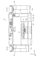
図2は、図1の状態からオートドキュメントフィーダー16を取り外した状態におけるプリンター11を正面側から見た図である。
FIG. 2 is a diagram of the
破線13aは、原稿Gが載置される原稿台の高さ方向における位置を示す。インク供給装置15a,15bは、蓋体21が閉じた状態において、蓋体21の上端21aの位置が読み取り面(原稿台)の高さ方向の位置13aと同じか、または位置13aより低い位置になるように備えられる。
A
このような構成により、使用者が、図1のオートドキュメントフィーダー16を持ち上げて回動させて原稿台を開放してから、原稿台に原稿Gを載置し、読取部13によって原稿Gの画像を読み取らせた後に、原稿Gを原稿台から取り除くまでの動作において操作性がよい。また、原稿Gのサイズが、原稿台からはみだすほど大きな場合に、特に原稿台の左右方向にはみだした原稿Gがインク供給装置15a,15bに干渉することがなく操作性が良い。また、インク供給装置15a,15bの上面の高さを、原稿台の高さと略同一に設定しておけば、はみだした原稿Gを支持することができ、原稿Gが撓むことによる原稿Gの損傷を防止することができる。
With such a configuration, the user lifts and rotates the
図3は、インク供給装置15a,15bの蓋体21を取り外した状態におけるプリンター11の斜視図である。インク供給装置15aには、モノクロインクを収容する1個のインク収容体17aが着脱可能に備えられる。インク供給装置15bには、イエロー、マゼンタ、シアンのカラーインクをそれぞれ収容する3個のインク収容体17bが着脱可能に備えられる。インク収容体17aにインクを収容可能なインク容量は、インク収容体17bにインクを収容可能なインク容量より多い。また、3個のインク収容体17bのインク容量は、略同じである。
FIG. 3 is a perspective view of the
図4は、インク収容体17a,17bの斜視図である。インク収容体17a,17bは、インクを収容するインク袋90を備えている。インク袋90における上端側には、支持部材(ハンガー部材)92が取着されている。すなわちインク袋90は、支持部材92と係合している。
FIG. 4 is a perspective view of the
インク袋90は、2つの矩形状の可撓性フィルム90aの周縁に筒状のインク導出部(図示略)を挟んだ状態でこれら2つの可撓性フィルム90aの周縁同士を溶着することによって形成される。
The
インク収容体17a,17bの支持部材92は、インク袋90の上端部に対して当該上端部を互いに挟むように取り付けられる第1支持部材105及び第2支持部材106を備えている。また、第2支持部材106における両端部には、インク袋90に形成されたインク袋貫通孔(図示略)に挿通される円柱状の凸部123がそれぞれ突設されている。また、第2支持部材106には、インク袋貫通孔に挿通された凸部123と係合する係合切欠凹部130が形成されている。
The
3個のインク収容体17bは、第1支持部材105の長手方向が左右方向に対して傾斜した角度(例えば30度)の姿勢で、突片部122を容器本体20内の凹部(不図示)に保持させる。
The three
インク収容体17a,17bの上部には、弁体部(図示略)が設けられており、キャップ87を押し下げる方向に回転させることによって弁体部が動作し、インク収容体17a,17bの内部と接続チューブ37a,37bとが連通状態となる。
A valve body (not shown) is provided on the upper portions of the
インク供給装置15aのケース18における奥行きの長さは、インク供給装置15bのケース18における奥行きの長さより短い。そして、インク供給装置15aおよびインク供給装置15bの正面側の端部の位置は、前後方向において略同じ位置にあるが、インク供給装置15aの背面側の位置は、インク供給装置15bの背面側の位置より前側にある。そのため、筐体25の左側背面部には、インク供給装置15aが配置されない。
The depth of the
このような構成により、使用者が、電源コードに接続されて交流電源を供給するためのプラグ(不図示)を、筐体25の左側背面部に設けられたプラグ受け(不図示)に接続する際の接続作業を容易にすることができる。
With such a configuration, the user connects a plug (not shown) connected to the power cord to supply AC power to a plug receptacle (not shown) provided on the left rear surface of the
また、インク供給装置15aのケース18における幅の長さL1は、インク供給装置15bのケース18における幅の長さL2より短く、インク供給装置15aのケース18における高さ方向の長さは、インク供給装置15bのケース18における高さ方向の長さより短い。このように、インク供給装置15aのケース18とインク供給装置15bのケース18の大きさが異なる。
Further, the width L1 of the
図5は、筐体25の上部を取り外した状態におけるプリンター11の斜視図である。印刷部12は、左右方向に長い略直方体状の筐体25を備えている。筐体25内の中央部には、記録媒体としての用紙Pを支持する支持台26が設けられている。支持台26の上方には、主走査方向である左右方向に往復移動可能なキャリッジ27が設けられている。
FIG. 5 is a perspective view of the
キャリッジ27内には、キャリッジ27の下面から露出するようにインクを噴射する記録ヘッド28が支持されている。記録ヘッド28は、支持台26と対向している。記録ヘッド28は、キャリッジ27が左右方向に移動しながら支持台26上を後側から前側に向かって搬送される用紙Pに対して複数のノズル(図示略)からインクを噴射することで、用紙Pに印刷を行う。
A
用紙カセット29は、筐体25内における支持台26の下側に備えられる。用紙カセット29内の用紙Pは、紙送り機構(図示略)により、一枚ずつ反転されながら支持台26上へ後側から給送される。
The
支持台26上で印刷された用紙Pは、開口部30における用紙カセット29よりも上側の領域によって構成される図1の排紙口31から順次排紙される。
The paper P printed on the
筐体25内における左端部には、前側が開口した矩形箱状をなすホルダーケース34が設けられる。ホルダーケース34内には、左右方向に並ぶ4個の中空のインク供給針(不図示)が備えられている。
A
各インク供給針は、前後方向に延びるとともに、ホルダーケース34の側壁を貫通している。可撓性のインク供給チューブ36の一端側は、各インク供給針の後端部に接続され、インク供給チューブ36の他端側は記録ヘッド28に接続されている。
Each ink supply needle extends in the front-rear direction and penetrates the side wall of the
1本の可撓性の接続チューブ37aの一端側は、インク供給針の前端部と接続され、接続チューブ37aの他端側は、インク供給装置15aに収容されるインク収容体17aと接続される(図3参照)。
One end of one
3本の可撓性の接続チューブ37bの一端側は、各インク供給針の前端部と接続され、接続チューブ37bの他端側は、インク供給装置15bに収容される各インク収容体17bと接続される(図3参照)。
One end side of the three
インク収容体17a,17bの上部には、弁体部(図示略)が設けられており、キャップ87を押し下げる方向に回転させることによって弁体部が動作し、インク収容体17a,17bの内部と接続チューブ37a,37bとが連通状態となる。
A valve body (not shown) is provided on the upper portions of the
従って、インク供給装置15aに収容されたインク収容体17aから接続チューブ37a、インク供給針、インク供給チューブ36を介して、記録ヘッド28にモノクロインクが供給される。
Accordingly, monochrome ink is supplied to the
また、インク供給装置15bに収容されたインク収容体17bから接続チューブ37b、インク供給針、インク供給チューブ36を介して、記録ヘッド28に、イエローインク、マゼンタインク、シアンインクのカラーインクがそれぞれ供給される。
Further, yellow ink, magenta ink, and cyan ink are supplied to the
本実施形態における用紙カセット29は記録媒体保持ユニットを構成し、インク収容体17a,17bは液体収容体を構成し、ケース18は保持体を構成する。
The
以上、本実施形態のプリンター11は、インクを用紙Pに噴射可能な記録ヘッドと、用紙Pを保持する用紙カセット29と、用紙Pを記録ヘッドに搬送する搬送ユニットと、記録ヘッドと搬送ユニットとを収容し、用紙カセット29が挿入される筐体25と、筐体25の外側面に形成され、用紙カセット29を挿入する挿入口(開口部30)と、インクを収容するインク収容体17a,17bと、筐体25の開口部30が形成された外側面に隣接する両側の外側面に配置され、インク収容体を保持するケース18と、インク収容体から筐体25の内部にインクを供給する供給部(接続チューブ37a,37bを少なくとも含む)と、を備え、両側のケース18の大きさが異なる。
As described above, the
この構成により、インクの種類によって異なる使用量に応じてインク収容体17a,17bの大きさや個数を変えてケース18に備えることができる。そのため、プリンター11の大型化を抑制できる。また、インク収容体17a,17bを筐体25の両側に備えるので、左右の重量バランスが向上し、本体装置14が不安定になることを抑制する。
With this configuration, it is possible to prepare the
本実施形態では、両側のケース18において、奥行き、幅、高さが異なったが、奥行き、幅、高さのうちの少なくとも一つが異なるケースを備えてもよい。
In the present embodiment, the
また、両側のケース18のうちの小さいほうのインク供給装置15aのケース18には容量の大きなインク収容体17aが保持され、大きいほうのインク供給装置15bのケース18には容量の小さなインク収容体17bが保持され、大きいほうの右側のケース18には、小さいほうの左側のケース18のインク収容体17a(1個)よりも多くの数のインク収容体17b(3個)が保持される。
In addition, a large
モノクロインクの使用量は、カラーインクの使用量より多い。そこで、このような構成にすることにより、インクの種類によって異なる使用量に応じて、インク収容体17a,17bを配置することができる。
The amount of monochrome ink used is greater than the amount of color ink used. Thus, with such a configuration, the
また、両側のケース18には、同数のインク収容体が保持され、大きいほうのケースに保持されるインク収容体のうちの少なくとも1つは他のインク収容体よりも容量が多いようにしてもよい。
The
これにより、モノクロインクやカラーインクなどのインクの種類によって異なる使用量に応じて、インク収容体を配置することができる。 Accordingly, the ink container can be arranged according to the amount of use that varies depending on the type of ink such as monochrome ink or color ink.
また、筐体25を挿入口(開口部30)が形成された側から見た方向において、両側のケース18において、右側のケース18には、左側のケース18の1個のインク収容体17aより多い3個のインク収容体17bが保持される。
Further, in the
これにより、右利きの使用者がケース18にインク収容体17bを取り付けたり、取り外したりするときの操作性がよい。
Thereby, the operability when a right-handed user attaches or removes the
インク収容体17a,17bは可撓性である。これにより、インクの消費に応じてインク収容体17a,17bのインク袋90が収縮するので、インク袋90内部が負圧となってしまい、インクの記録ヘッド28側への供給が不可となることを防止できる。
The
(実施形態2)
実施形態1では、蓋体21の回動軸が背面側に設けられて、正面側が開口するケース18について説明したが、実施形態2では、前後方向に延びる回動軸が蓋体21の下部に設けられて、筐体の側面側が開口するケースについて説明する。
(Embodiment 2)
In the first embodiment, the
図6(a)は、実施形態2におけるインク供給装置210が備えられた側の部分を示す外観斜視図である。図6(b)は、インク供給装置210が備えられた側の部分を、正面側から見た図である。インク供給装置210のケース209は、容器本体207と蓋体208とから構成される。
FIG. 6A is an external perspective view illustrating a portion on the side where the
図6(b)に示すように、蓋体208は、蓋体208における下部に設けられて軸方向が前後方向に延びる回動軸216を支点として、矢印方向に回動する。これにより、蓋体208の右側が開口可能に備えられる。
As shown in FIG. 6B, the
本体装置203は、読取部201と印刷部202とから構成される。読取部201の右側には、印刷部202を収容する筐体205の壁面より右側に突出した庇部204が形成される。すなわち、図6(b)に示すように、庇部204は、左右方向において、容器本体207と重なる位置にある。これにより、プリンター200が大型化することを抑制できる。
The
蓋体208の下部は他の部分よりも蓋体208の厚さが薄く、下部がすぼむ形状となっている。このすぼんだ蓋体208の下部には、蓋体208のすぼんだ壁面212より外側に凸状に突出した凸部211が形成される。凸部の突出量は他のすぼんでいない領域と同等である。言い換えるとすぼんでいる領域があることによって、相対的に凸部が突出した形状となっている。蓋体208の下部内側の壁面には、凸部211の形状に沿って形成された凹部(不図示)が形成される。これにより、この凹部に、容器本体207に収容されたインク収容体(図4参照)の下部の一端側を保持させることができる。
The lower part of the
蓋体208には透明性を有する透明部材213が設けられる。これにより、容器本体207に収容されたインク収容体を視認可能な窓として機能する。そのため、透明部材213の外側からケース209内の全てのインク収容体のインク袋の萎み具合をケース209の前側から視認することができる。このため、各インク収容体のインク袋90の萎み具合から各インク収容体の交換時期を認識できる。
The
図6(a)の蓋体208には、蓋体208を開閉する際の開閉レバー214が設けられる。開閉レバー214は、容器本体207に収容された複数のインク収容体の間の位置に設けられる。開閉レバー214には容器本体207と蓋体208とを閉状態に固定するためのロック機構や不図示のフック等の構造物が含まれており、それらの設置スペースが必要となる。このような場合であっても、開閉レバー214を、容器本体207に収容された複数のインク収容体の間の位置に設けることにより、ケース209の幅の長さを短くすることができる。
The
蓋体208と容器本体207とには蓋体208を閉状態に維持可能なロック機構215が備えられる。図6(c)は、ロック機構215の概略構成を示す図である。ロック機構215は、所謂シリンダー錠によって構成される。
The
蓋体208の上部には保持部材217が備えられる。保持部材217には、回動部材218が回動可能に備えられる。回動部材218の端部にはレバー219が備えられる。使用者が、キー221を回動部材218の開口部に挿入し、回動させるとレバー219が回動し、容器本体207に設けられた係合部220と係合し、蓋体208は容器本体207に対して閉状態となる。
A holding
筐体205の下には、筐体205の挿入口に挿抜可能に設けられた用紙カセット(不図示)とは別に増設カセットユニット206が備えられる。ケース209の下端部は、筐体205の底部205aより下側の位置にあり、ケース209の下端部は、増設カセットユニット206の底部206aより上側の位置にある。
An
増設カセットユニット206の底部206aの右側角部には、凹状の取っ手部222が前後方向に長く設けられる。取っ手部222は、上下方向において、蓋体208と容器本体207と重ならない位置に設けられる。インク供給装置210が筐体205に装着された状態で、使用者は、取っ手部222を把持し、増設カセットユニット206と、増設カセットユニット206に搭載された本体装置203とを保持した状態でプリンター200を持ち上げて移動することができる。また、取っ手部222が明確に示されることにより、移動時に誤ってインク供給装置15a、15bを保持してしまい、インク供給装置15a、15bを損傷してしまうことを防止できる。
At the right corner of the bottom 206a of the
11,200…インクジェット式プリンター、13,201…読取部、17a,17b…インク収容体、18,209…ケース、25,205…筐体、28…記録ヘッド、29,140…用紙カセット、30…開口部、37a,37b…接続チューブ、90a…可撓性フィルム、211…凸部、213…透明部材、L1,L2…幅の長さ。 DESCRIPTION OF SYMBOLS 11,200 ... Inkjet printer, 13, 201 ... Reading part, 17a, 17b ... Ink container, 18, 209 ... Case, 25, 205 ... Housing, 28 ... Recording head, 29, 140 ... Paper cassette, 30 ... Opening part, 37a, 37b ... connection tube, 90a ... flexible film, 211 ... convex part, 213 ... transparent member, L1, L2 ... length of width.
Claims (10)
前記記録媒体を保持する記録媒体保持ユニットと、
前記記録媒体保持ユニットから前記記録媒体を前記記録ヘッドに搬送する搬送ユニットと、
前記記録ヘッドと前記搬送ユニットとを収容し、前記記録媒体保持ユニットが挿入される筐体と、
前記筐体の外側面に形成され、前記記録媒体保持ユニットを挿入する挿入口と、
前記筐体の前記挿入口が形成された外側面に隣接する一方の外側面に取り付けられ、前記液体を収容する第1の液体収容体を保持する前記筐体とは別に形成された第1の保持体と、
前記筐体の前記挿入口が形成された外側面に隣接する他方の外側面に取り付けられ、前記液体を収容する第2の液体収容体を保持する前記筐体とは別に形成された第2の保持体と、
前記第1の液体収容体および前記第2の液体収容体から前記筐体の前記記録ヘッドに前記液体を供給する供給部と、
を備え、
前記第1の保持体と前記第2の保持体の大きさが異なり、
前記第1の液体収容体および第2の液体収容体は可撓性を有し、前記第1の保持体および前記第2の保持体に保持された状態における上方に支持部材が取り付けられ、当該支持部材によって前記第1の保持体および前記第2の保持体に着脱可能に保持されるとともに、当該支持部材を介して前記供給部が接続されることを特徴とする記録装置。 A recording head capable of ejecting liquid onto a recording medium;
A recording medium holding unit for holding the recording medium;
A transport unit for transporting the recording medium from the recording medium holding unit to the recording head;
A housing that houses the recording head and the transport unit, and into which the recording medium holding unit is inserted;
An insertion port formed on the outer surface of the housing for inserting the recording medium holding unit;
The first casing is attached to one outer surface adjacent to the outer surface on which the insertion port is formed, and is formed separately from the casing that holds the first liquid container that stores the liquid. Holding body,
A second attachment formed on the other outer surface adjacent to the outer surface on which the insertion port of the housing is formed and formed separately from the housing for holding the second liquid container for containing the liquid. Holding body,
A supply unit for supplying the liquid from the first liquid container and the second liquid container to the recording head of the housing;
With
Wherein Ri is Do different sizes of the first holding member and the second holding member,
The first liquid container and the second liquid container have flexibility, and a support member is attached to the upper side in a state of being held by the first holder and the second holder, A recording apparatus, wherein the recording apparatus is detachably held by the first holding body and the second holding body by a support member, and the supply unit is connected via the support member.
前記第1の保持体と前記第2の保持体は、奥行き、幅、高さのうちの少なくとも一つが異なることを特徴とする記録装置。 The recording apparatus according to claim 1 ,
The recording apparatus, wherein the first holding body and the second holding body are different in at least one of depth, width, and height.
前記第1の保持体の大きさは、前記第2の保持体の大きさよりも小さいことを特徴とする記録装置。 The recording apparatus according to claim 1 , wherein the recording apparatus is a recording apparatus according to claim 1 .
The size of the first holding body is smaller than the size of the second holding body.
前記第2の保持体に保持される前記第2の液体収容体の数は、前記第1の保持体に保持される前記第1の液体収容体の数よりも多いことを特徴とする記録装置。 The recording apparatus according to claim 3 ,
The number of the second liquid containers held by the second holding body is larger than the number of the first liquid containers held by the first holding body. .
前記第2の保持体に収容される複数の前記第2の液体収容体は、前記筐体の前記記録媒体保持ユニットが挿入される前記挿入口が形成された外側面の延在方向に対して、斜めになるように収容されることを特徴とする記録装置。 The recording apparatus according to claim 4 ,
The plurality of second liquid containers accommodated in the second holder are extending in an extending direction of an outer surface of the housing in which the insertion port into which the recording medium holding unit is inserted is formed. The recording apparatus is housed so as to be inclined.
前記第1の保持体の複数の前記液体収容体は、前記筐体の前記第1の保持体が配置された外側面の延在方向に沿うように収容されることを特徴とする記録装置。 The recording apparatus according to claim 4 or 5 , wherein
The recording apparatus according to claim 1, wherein the plurality of liquid containers of the first holding body are accommodated along an extending direction of an outer surface of the housing where the first holding body is disposed.
前記筐体を前記挿入口が形成された側から見た方向において、前記第2の保持体は右側に配置されることを特徴とする記録装置。 The recording apparatus according to any one of claims 4 to 6 ,
The recording apparatus according to claim 1, wherein the second holding body is disposed on the right side when the housing is viewed from the side where the insertion port is formed.
前記第1の液体収容体の総容量は、前記第2の液体収容体の総容量とほぼ等しいことを特徴とする記録装置。 The recording apparatus according to any one of claims 4 to 7 ,
The recording apparatus according to claim 1, wherein a total capacity of the first liquid container is substantially equal to a total capacity of the second liquid container.
前記第1の保持体および前記第2の保持体の下部には、外側に凸となる凸部が形成され、保持される前記第1の液体収容体および第2の液体収容体は当該凸部に対応して配置されることを特徴とする記録装置。 A recording apparatus according to any one of claims 1 to 8,
The first holding body and the second holding body are formed with convex portions protruding outward, and the first liquid container and the second liquid container to be held are the convex portions. The recording apparatus is arranged corresponding to the above.
前記記録媒体を保持する記録媒体保持ユニットと、
前記記録媒体保持ユニットから前記記録媒体を前記記録ヘッドに搬送する搬送ユニットと、
前記記録ヘッドと前記搬送ユニットとを収容し、前記記録媒体保持ユニットが挿入される筐体と、
前記筐体の外側面に形成され、前記記録媒体保持ユニットを挿入する挿入口と、
前記筐体の前記挿入口が形成された外側面に隣接する一方の外側面に取り付けられ、前記液体を収容する第1の液体収容体を保持する前記筐体とは別に形成された第1の保持体と、
前記筐体の前記挿入口が形成された外側面に隣接する他方の外側面に取り付けられ、前記液体を収容する第2の液体収容体を保持する前記筐体とは別に形成された第2の保持体と、
前記第1の液体収容体および前記第2の液体収容体から前記筐体の前記記録ヘッドに前記液体を供給する供給部と、
原稿台に載置された原稿に描かれた画像を読み取る読取部と、
を備え、
前記第1の保持体と前記第2の保持体の大きさが異なり、
前記第1の保持体および第2の保持体の最上部の位置は、前記原稿台と同じ位置にあることを特徴とする記録装置。 A recording head capable of ejecting liquid onto a recording medium;
A recording medium holding unit for holding the recording medium;
A transport unit for transporting the recording medium from the recording medium holding unit to the recording head;
A housing that houses the recording head and the transport unit, and into which the recording medium holding unit is inserted;
An insertion port formed on the outer surface of the housing for inserting the recording medium holding unit;
The first casing is attached to one outer surface adjacent to the outer surface on which the insertion port is formed, and is formed separately from the casing that holds the first liquid container that stores the liquid. Holding body,
A second attachment formed on the other outer surface adjacent to the outer surface on which the insertion port of the housing is formed and formed separately from the housing for holding the second liquid container for containing the liquid. Holding body,
A supply unit for supplying the liquid from the first liquid container and the second liquid container to the recording head of the housing;
A reading unit for reading an image drawn on a document placed on a document table ;
With
The first holding body and the second holding body have different sizes,
An uppermost position of the first holding body and the second holding body is in the same position as the document table.
Priority Applications (7)
| Application Number | Priority Date | Filing Date | Title |
|---|---|---|---|
| JP2013177661A JP6330275B2 (en) | 2013-08-29 | 2013-08-29 | Recording device |
| EP14839612.0A EP3040204B1 (en) | 2013-08-29 | 2014-08-22 | Storage device |
| US14/913,572 US9498968B2 (en) | 2013-08-29 | 2014-08-22 | Recording apparatus |
| PCT/JP2014/004339 WO2015029405A1 (en) | 2013-08-29 | 2014-08-22 | Storage device |
| CN201480045967.XA CN105517805B (en) | 2013-08-29 | 2014-08-22 | Tape deck |
| PH12016500259A PH12016500259A1 (en) | 2013-08-29 | 2016-02-05 | Recording apparatus |
| US15/297,915 US9821559B2 (en) | 2013-08-29 | 2016-10-19 | Recording apparatus |
Applications Claiming Priority (1)
| Application Number | Priority Date | Filing Date | Title |
|---|---|---|---|
| JP2013177661A JP6330275B2 (en) | 2013-08-29 | 2013-08-29 | Recording device |
Publications (3)
| Publication Number | Publication Date |
|---|---|
| JP2015044370A JP2015044370A (en) | 2015-03-12 |
| JP2015044370A5 JP2015044370A5 (en) | 2016-09-15 |
| JP6330275B2 true JP6330275B2 (en) | 2018-05-30 |
Family
ID=52585995
Family Applications (1)
| Application Number | Title | Priority Date | Filing Date |
|---|---|---|---|
| JP2013177661A Active JP6330275B2 (en) | 2013-08-29 | 2013-08-29 | Recording device |
Country Status (6)
| Country | Link |
|---|---|
| US (2) | US9498968B2 (en) |
| EP (1) | EP3040204B1 (en) |
| JP (1) | JP6330275B2 (en) |
| CN (1) | CN105517805B (en) |
| PH (1) | PH12016500259A1 (en) |
| WO (1) | WO2015029405A1 (en) |
Families Citing this family (7)
| Publication number | Priority date | Publication date | Assignee | Title |
|---|---|---|---|---|
| JP6330275B2 (en) | 2013-08-29 | 2018-05-30 | セイコーエプソン株式会社 | Recording device |
| CN106536208A (en) | 2014-08-05 | 2017-03-22 | 精工爱普生株式会社 | Composite device |
| JP6631019B2 (en) * | 2015-03-12 | 2020-01-15 | セイコーエプソン株式会社 | Liquid container unit |
| JP6672783B2 (en) * | 2015-12-24 | 2020-03-25 | セイコーエプソン株式会社 | Tank unit, printer |
| JP6790357B2 (en) * | 2015-12-24 | 2020-11-25 | セイコーエプソン株式会社 | printer |
| US10343409B2 (en) | 2015-06-09 | 2019-07-09 | Seiko Epson Corporation | Liquid jet apparatus, tank unit, and printer |
| JP7247746B2 (en) * | 2019-05-21 | 2023-03-29 | セイコーエプソン株式会社 | recording device |
Family Cites Families (24)
| Publication number | Priority date | Publication date | Assignee | Title |
|---|---|---|---|---|
| JP4193719B2 (en) * | 2003-03-05 | 2008-12-10 | セイコーエプソン株式会社 | Liquid container, liquid ejecting apparatus, and liquid container case |
| US5369429A (en) * | 1993-10-20 | 1994-11-29 | Lasermaster Corporation | Continuous ink refill system for disposable ink jet cartridges having a predetermined ink capacity |
| JP3572854B2 (en) * | 1996-04-05 | 2004-10-06 | セイコーエプソン株式会社 | Inkjet printer and damper |
| JPH106525A (en) * | 1996-06-26 | 1998-01-13 | Ricoh Co Ltd | Ink cartridge package and ink jet recording apparatus |
| JPH1158792A (en) * | 1997-08-21 | 1999-03-02 | Seiko Epson Corp | Ink jet recorder and ink cartridge |
| JP2000280570A (en) * | 1999-03-31 | 2000-10-10 | Brother Ind Ltd | Image forming apparatus |
| US6338553B1 (en) * | 2000-05-15 | 2002-01-15 | Hewlett-Packard Company Intellectual Property Administration | Ink supply tube guiding system for large format printer |
| US7370949B2 (en) * | 2002-02-28 | 2008-05-13 | Seiko Epson Corporation | Liquid supplying member, method of manufacturing the same, and liquid ejection apparatus incorporating the same |
| US7008051B2 (en) * | 2002-10-10 | 2006-03-07 | Akermalm Per G | Expanded ink supply system for ink jet printers |
| JP2007044885A (en) * | 2005-08-05 | 2007-02-22 | Seiko Epson Corp | Inkjet recorder, its controlling method, its maintenance method and its cartridge for maintenance |
| EP2014889A1 (en) | 2007-06-20 | 2009-01-14 | Ford Global Technologies, LLC | A method for thermally managing an internal combustion engine |
| JP4645682B2 (en) * | 2007-06-20 | 2011-03-09 | セイコーエプソン株式会社 | Fluid ejecting apparatus and manufacturing method thereof |
| JP4766011B2 (en) | 2007-06-20 | 2011-09-07 | セイコーエプソン株式会社 | Fluid ejecting apparatus and manufacturing method thereof |
| US7959268B2 (en) | 2007-06-20 | 2011-06-14 | Seiko Epson Corporation | Installing fluid container in fluid ejection device |
| JP2009202346A (en) | 2008-02-26 | 2009-09-10 | Mimaki Engineering Co Ltd | Printer system and external ink supplying device |
| JP2013023846A (en) | 2011-07-19 | 2013-02-04 | Nippon Hume Corp | Connection part structure of propulsion pipe |
| JP6044068B2 (en) * | 2011-12-14 | 2016-12-14 | セイコーエプソン株式会社 | Recording device |
| JP2013123847A (en) * | 2011-12-14 | 2013-06-24 | Seiko Epson Corp | Liquid supply system |
| JP5998471B2 (en) * | 2011-12-20 | 2016-09-28 | セイコーエプソン株式会社 | adapter |
| JP5948929B2 (en) * | 2012-02-10 | 2016-07-06 | セイコーエプソン株式会社 | Recording device |
| JP2013180465A (en) * | 2012-03-01 | 2013-09-12 | Seiko Epson Corp | Inkjet recording apparatus |
| JP5991462B2 (en) * | 2012-02-29 | 2016-09-14 | セイコーエプソン株式会社 | Recording device |
| JP6221303B2 (en) * | 2013-03-29 | 2017-11-01 | セイコーエプソン株式会社 | Liquid ejector |
| JP6330275B2 (en) | 2013-08-29 | 2018-05-30 | セイコーエプソン株式会社 | Recording device |
-
2013
- 2013-08-29 JP JP2013177661A patent/JP6330275B2/en active Active
-
2014
- 2014-08-22 WO PCT/JP2014/004339 patent/WO2015029405A1/en active Application Filing
- 2014-08-22 CN CN201480045967.XA patent/CN105517805B/en active Active
- 2014-08-22 EP EP14839612.0A patent/EP3040204B1/en active Active
- 2014-08-22 US US14/913,572 patent/US9498968B2/en active Active
-
2016
- 2016-02-05 PH PH12016500259A patent/PH12016500259A1/en unknown
- 2016-10-19 US US15/297,915 patent/US9821559B2/en active Active
Also Published As
| Publication number | Publication date |
|---|---|
| CN105517805B (en) | 2017-06-13 |
| CN105517805A (en) | 2016-04-20 |
| EP3040204A4 (en) | 2017-07-19 |
| US20160207320A1 (en) | 2016-07-21 |
| US9498968B2 (en) | 2016-11-22 |
| EP3040204A1 (en) | 2016-07-06 |
| US9821559B2 (en) | 2017-11-21 |
| PH12016500259B1 (en) | 2016-05-16 |
| JP2015044370A (en) | 2015-03-12 |
| EP3040204B1 (en) | 2018-09-19 |
| PH12016500259A1 (en) | 2016-05-16 |
| WO2015029405A1 (en) | 2015-03-05 |
| US20170190183A1 (en) | 2017-07-06 |
Similar Documents
| Publication | Publication Date | Title |
|---|---|---|
| JP6330275B2 (en) | Recording device | |
| US9834001B2 (en) | Recording apparatus | |
| JP5887295B2 (en) | Ink container and ink jet image forming apparatus | |
| US12023941B2 (en) | Inkjet printer | |
| JP6326741B2 (en) | Recording device | |
| TW201800268A (en) | Recording device solves the problem of residual printer ink amount adversely affected by dust or damage from the outside of the printer | |
| JP2017081094A (en) | Liquid consuming device | |
| JP7243048B2 (en) | printer | |
| US9073332B2 (en) | Inkjet recording apparatus, multifunction device, and ink cartridge container | |
| JP6330355B2 (en) | Recording device | |
| JP6229373B2 (en) | Recording device | |
| JP6264083B2 (en) | Recording device | |
| JP2015066822A (en) | Recording device | |
| WO2016021171A1 (en) | Composite device | |
| JP2018065363A (en) | Supply device | |
| JP6299085B2 (en) | Recording device | |
| JP2016101751A (en) | Ink cartridge and printer | |
| JP2015112777A (en) | Recording device | |
| JP2015066823A (en) | Recording device | |
| JP2012176581A (en) | Image forming apparatus | |
| JP2016196150A (en) | Liquid container storage device and image formation device |
Legal Events
| Date | Code | Title | Description |
|---|---|---|---|
| RD04 | Notification of resignation of power of attorney |
Free format text: JAPANESE INTERMEDIATE CODE: A7424 Effective date: 20150114 |
|
| RD04 | Notification of resignation of power of attorney |
Free format text: JAPANESE INTERMEDIATE CODE: A7424 Effective date: 20160617 |
|
| RD03 | Notification of appointment of power of attorney |
Free format text: JAPANESE INTERMEDIATE CODE: A7423 Effective date: 20160627 |
|
| A521 | Written amendment |
Free format text: JAPANESE INTERMEDIATE CODE: A523 Effective date: 20160728 |
|
| A621 | Written request for application examination |
Free format text: JAPANESE INTERMEDIATE CODE: A621 Effective date: 20160728 |
|
| A131 | Notification of reasons for refusal |
Free format text: JAPANESE INTERMEDIATE CODE: A131 Effective date: 20170808 |
|
| A521 | Written amendment |
Free format text: JAPANESE INTERMEDIATE CODE: A523 Effective date: 20170905 |
|
| A131 | Notification of reasons for refusal |
Free format text: JAPANESE INTERMEDIATE CODE: A131 Effective date: 20180306 |
|
| A521 | Written amendment |
Free format text: JAPANESE INTERMEDIATE CODE: A523 Effective date: 20180312 |
|
| TRDD | Decision of grant or rejection written | ||
| A01 | Written decision to grant a patent or to grant a registration (utility model) |
Free format text: JAPANESE INTERMEDIATE CODE: A01 Effective date: 20180327 |
|
| A61 | First payment of annual fees (during grant procedure) |
Free format text: JAPANESE INTERMEDIATE CODE: A61 Effective date: 20180409 |
|
| R150 | Certificate of patent or registration of utility model |
Ref document number: 6330275 Country of ref document: JP Free format text: JAPANESE INTERMEDIATE CODE: R150 |