EP3506018B1 - Image forming apparatus - Google Patents
Image forming apparatus Download PDFInfo
- Publication number
- EP3506018B1 EP3506018B1 EP19155304.9A EP19155304A EP3506018B1 EP 3506018 B1 EP3506018 B1 EP 3506018B1 EP 19155304 A EP19155304 A EP 19155304A EP 3506018 B1 EP3506018 B1 EP 3506018B1
- Authority
- EP
- European Patent Office
- Prior art keywords
- unit
- communication
- housing
- image forming
- forming apparatus
- Prior art date
- Legal status (The legal status is an assumption and is not a legal conclusion. Google has not performed a legal analysis and makes no representation as to the accuracy of the status listed.)
- Active
Links
- 230000006854 communication Effects 0.000 claims description 219
- 238000004891 communication Methods 0.000 claims description 219
- 239000000976 ink Substances 0.000 description 62
- 238000007599 discharging Methods 0.000 description 12
- 238000012423 maintenance Methods 0.000 description 9
- 238000012986 modification Methods 0.000 description 9
- 230000004048 modification Effects 0.000 description 9
- 239000004973 liquid crystal related substance Substances 0.000 description 7
- 230000006870 function Effects 0.000 description 5
- 238000000034 method Methods 0.000 description 5
- 230000033001 locomotion Effects 0.000 description 4
- 230000007246 mechanism Effects 0.000 description 4
- 239000003086 colorant Substances 0.000 description 3
- 238000011161 development Methods 0.000 description 3
- 238000002347 injection Methods 0.000 description 3
- 239000007924 injection Substances 0.000 description 3
- 238000012546 transfer Methods 0.000 description 3
- 239000004020 conductor Substances 0.000 description 2
- 238000010586 diagram Methods 0.000 description 2
- 238000006073 displacement reaction Methods 0.000 description 2
- 238000010438 heat treatment Methods 0.000 description 2
- 230000008569 process Effects 0.000 description 2
- 230000007723 transport mechanism Effects 0.000 description 2
- 230000003466 anti-cipated effect Effects 0.000 description 1
- 230000007175 bidirectional communication Effects 0.000 description 1
- 230000005540 biological transmission Effects 0.000 description 1
- 230000015572 biosynthetic process Effects 0.000 description 1
- 239000002131 composite material Substances 0.000 description 1
- 238000013461 design Methods 0.000 description 1
- 230000005674 electromagnetic induction Effects 0.000 description 1
- 238000012840 feeding operation Methods 0.000 description 1
- 238000009434 installation Methods 0.000 description 1
- 238000004519 manufacturing process Methods 0.000 description 1
- 239000000463 material Substances 0.000 description 1
- 108091008695 photoreceptors Proteins 0.000 description 1
- 230000009467 reduction Effects 0.000 description 1
- 229920003002 synthetic resin Polymers 0.000 description 1
- 239000000057 synthetic resin Substances 0.000 description 1
Images


Classifications
-
- H—ELECTRICITY
- H04—ELECTRIC COMMUNICATION TECHNIQUE
- H04N—PICTORIAL COMMUNICATION, e.g. TELEVISION
- H04N1/00—Scanning, transmission or reproduction of documents or the like, e.g. facsimile transmission; Details thereof
- H04N1/00519—Constructional details not otherwise provided for, e.g. housings, covers
- H04N1/00559—Mounting or support of components or elements
-
- B—PERFORMING OPERATIONS; TRANSPORTING
- B41—PRINTING; LINING MACHINES; TYPEWRITERS; STAMPS
- B41J—TYPEWRITERS; SELECTIVE PRINTING MECHANISMS, i.e. MECHANISMS PRINTING OTHERWISE THAN FROM A FORME; CORRECTION OF TYPOGRAPHICAL ERRORS
- B41J29/00—Details of, or accessories for, typewriters or selective printing mechanisms not otherwise provided for
- B41J29/02—Framework
-
- B—PERFORMING OPERATIONS; TRANSPORTING
- B41—PRINTING; LINING MACHINES; TYPEWRITERS; STAMPS
- B41J—TYPEWRITERS; SELECTIVE PRINTING MECHANISMS, i.e. MECHANISMS PRINTING OTHERWISE THAN FROM A FORME; CORRECTION OF TYPOGRAPHICAL ERRORS
- B41J29/00—Details of, or accessories for, typewriters or selective printing mechanisms not otherwise provided for
- B41J29/12—Guards, shields or dust excluders
- B41J29/13—Cases or covers
-
- G—PHYSICS
- G03—PHOTOGRAPHY; CINEMATOGRAPHY; ANALOGOUS TECHNIQUES USING WAVES OTHER THAN OPTICAL WAVES; ELECTROGRAPHY; HOLOGRAPHY
- G03G—ELECTROGRAPHY; ELECTROPHOTOGRAPHY; MAGNETOGRAPHY
- G03G15/00—Apparatus for electrographic processes using a charge pattern
- G03G15/50—Machine control of apparatus for electrographic processes using a charge pattern, e.g. regulating differents parts of the machine, multimode copiers, microprocessor control
- G03G15/5016—User-machine interface; Display panels; Control console
-
- G—PHYSICS
- G03—PHOTOGRAPHY; CINEMATOGRAPHY; ANALOGOUS TECHNIQUES USING WAVES OTHER THAN OPTICAL WAVES; ELECTROGRAPHY; HOLOGRAPHY
- G03G—ELECTROGRAPHY; ELECTROPHOTOGRAPHY; MAGNETOGRAPHY
- G03G15/00—Apparatus for electrographic processes using a charge pattern
- G03G15/50—Machine control of apparatus for electrographic processes using a charge pattern, e.g. regulating differents parts of the machine, multimode copiers, microprocessor control
- G03G15/5075—Remote control machines, e.g. by a host
- G03G15/5087—Remote control machines, e.g. by a host for receiving image data
-
- G—PHYSICS
- G03—PHOTOGRAPHY; CINEMATOGRAPHY; ANALOGOUS TECHNIQUES USING WAVES OTHER THAN OPTICAL WAVES; ELECTROGRAPHY; HOLOGRAPHY
- G03G—ELECTROGRAPHY; ELECTROPHOTOGRAPHY; MAGNETOGRAPHY
- G03G15/00—Apparatus for electrographic processes using a charge pattern
- G03G15/50—Machine control of apparatus for electrographic processes using a charge pattern, e.g. regulating differents parts of the machine, multimode copiers, microprocessor control
- G03G15/5075—Remote control machines, e.g. by a host
- G03G15/5091—Remote control machines, e.g. by a host for user-identification or authorisation
-
- G—PHYSICS
- G03—PHOTOGRAPHY; CINEMATOGRAPHY; ANALOGOUS TECHNIQUES USING WAVES OTHER THAN OPTICAL WAVES; ELECTROGRAPHY; HOLOGRAPHY
- G03G—ELECTROGRAPHY; ELECTROPHOTOGRAPHY; MAGNETOGRAPHY
- G03G21/00—Arrangements not provided for by groups G03G13/00 - G03G19/00, e.g. cleaning, elimination of residual charge
- G03G21/16—Mechanical means for facilitating the maintenance of the apparatus, e.g. modular arrangements
- G03G21/1642—Mechanical means for facilitating the maintenance of the apparatus, e.g. modular arrangements for connecting the different parts of the apparatus
- G03G21/1657—Wireless connection means, e.g. RFID
-
- H—ELECTRICITY
- H04—ELECTRIC COMMUNICATION TECHNIQUE
- H04N—PICTORIAL COMMUNICATION, e.g. TELEVISION
- H04N1/00—Scanning, transmission or reproduction of documents or the like, e.g. facsimile transmission; Details thereof
- H04N1/00519—Constructional details not otherwise provided for, e.g. housings, covers
-
- H—ELECTRICITY
- H04—ELECTRIC COMMUNICATION TECHNIQUE
- H04N—PICTORIAL COMMUNICATION, e.g. TELEVISION
- H04N2201/00—Indexing scheme relating to scanning, transmission or reproduction of documents or the like, and to details thereof
- H04N2201/0008—Connection or combination of a still picture apparatus with another apparatus
- H04N2201/0034—Details of the connection, e.g. connector, interface
- H04N2201/0048—Type of connection
- H04N2201/0055—By radio
Definitions
- aspects of the present disclosure relate to an image forming apparatus which includes an antenna portion for short range wireless communication.
- a known image forming apparatus includes short-range wireless communication function which may be carried out between an image forming apparatus and a portable apparatus.
- short range wireless communication used herein is intended to signify wireless communication within a maximum range of, for example, 1 meter.
- JP 2005 22 7712 A discloses an image forming apparatus provided with a rotary developing device to inexpensively make a communication between radio communication tags and an antenna.
- a rotary developing device to inexpensively make a communication between radio communication tags and an antenna.
- communications take place between the radio communication tag 104 of the toner cartridge 56 of a previous developing unit 54 in a position right after it has moved from the developing position and the antenna of the communication device.
- a rotor 52 is rotated for development by the subsequent developing unit 54.
- the present developing unit 54 which has been in the developing position G1 moves.
- Communications take place between the radio communication tag 104 of the toner cartridge 56 of the developing unit 54 which has just moved from the developing position and the antenna 136 of the communication device.
- communications successively take place between the radio communication tags 104 of the toner cartridge 56 and the antenna 136 of the communication device.
- the antenna 136 of the communication device which is fewer than the radio communication tags 104. Namely, the inexpensive communication between the radio communication tags 104 and the antenna 136 of the communication device is made.
- US 2009/0184817 A1 discloses an image forming apparatus is supplied capable of improving distance precision and relative position precision of RFID tag and RFID unit so as to heighten communication quality of image forming apparatus.
- the image forming apparatus comprises attachable and removable exchange cartridge which is used for accommodating toner and has a RFID tag, and RFID unit that communicates with the RFID tag through radio communication, wherein the exchange cartridge is furnished as retreating in non-operational time; the exposure head unit is furnished movably; in the case that the exchange cartridge retreats, the exposure head unit moves together with the exchange cartridge.
- EP 1 182 520 A2 discloses a memory member usable with an electrophotographic image forming apparatus, includes a base; a storing element, provided in the base, for storing information; a memory antenna, provided in the base, for sending the information stored in the storing element to a main assembly antenna provided in a main assembly of the apparatus, when the memory member is mounted to the main assembly of the electrophotographic image forming apparatus; a sending member, provided in the base, for sending the information stored in the storing element to the memory antenna; and an outer casing member covering the base provided with the storing element, the sending member and the memory antenna.
- An image forming apparatus 1 is one practical example of an image forming apparatus according to aspects of the present disclosure.
- the matters specifying the claimed invention are not limited to particular members, structures or the like exemplified by the following illustrative embodiments.
- the illustrative embodiments are described with reference to the drawings.
- a housing 103 of an image forming apparatus 101 configures a design surface appearance of the image forming apparatus 101.
- an image forming unit 105 for forming an image on a sheet such as a paper sheet is accommodated as shown in FIG. 2 .
- the image forming unit 105 in the present illustrative embodiment is an image forming unit of the monochromatic type or an image forming member of the xerographic type having a photosensitive member 105A, a charger 105B, an exposure unit 105C, a transfer member 105D, a fixing unit 105E and so forth.
- the photosensitive member 105A carries a developer image thereon.
- the charger 105B charges the photosensitive member 105A.
- the exposure unit 105C exposes the surface of the charged photosensitive member 105A to form an electrostatic latent image on the surface of the photosensitive member 105A. Then, if charged developer is supplied to the photosensitive member 105A on which the electrostatic latent image is formed, then a developer image is carried on the surface of the photosensitive member 105A.
- the transfer member 105D is configured to transfer the developer image carried on the photosensitive member 105A to a sheet and is disposed at a position opposing to the photosensitive member 105A.
- the fixing unit 105E fixes the developer image transferred to the sheet. It is to be noted that the fixing unit 105E in the present illustrative embodiment is a fixing device of the heating type which heats the developer to deposit the developer onto the sheet.
- the sheet for which image formation is completed is discharged from a discharge port 107A to a discharge tray 107.
- the discharge port 107A in the present illustrative embodiment is open to the forward side at a rearward side upper portion of the housing 103.
- the discharge tray 107 is configured to have an inclined face which is inclined downward toward the discharge port 107A.
- a feed tray 109 is disposed which has a receiving portion 109A on which a plurality of sheets can be placed.
- the feed tray 109 is removably mounted on the apparatus main body, namely, on the housing 103.
- the feed tray 109 may be mounted on and removed from the housing 103 by moving the feed tray 109 in forward and backward directions.
- Sheets placed in a stacked state on the feed tray 109 are successively fed to the image forming unit 105 from the upper end side of the feed tray 109 in the stacking direction.
- a communication board 111 having an antenna portion 111A for short-range wireless communication is disposed as shown in FIG. 2 .
- the image forming apparatus 101 carries out short-range wireless communication with a communication device such as a portable apparatus (not shown) through the antenna portion 111A.
- a communication device such as a portable apparatus (not shown)
- the following acts can be carried out.
- the image forming apparatus 101 can be operated through an operation unit of the communication device.
- Image data to be formed on a sheet can be transmitted from the communication device to the image forming apparatus 101 directly without passing through a computer or the like so that it is printed by the image forming apparatus 101.
- a communication unit 111B which corresponds to the antenna portion 111A is provided at a position on the outer surface of the housing 103 at which the communication unit 111B may be seen without obstruction from the upper side as shown in FIG. 1 .
- the image forming apparatus 101 does not have any portion above the communication unit 111B. Therefore, in a region from above the communication unit 111B to the communication unit 111B, nothing blocks the field of vision of the user, and the user may see the communication unit 111B without obstruction from the upper side.
- the communication unit 111B is provided on an upper face of a forward side of the housing 103.
- An operation region 113 which is operated by a user is provided on the front side of the housing 103.
- the communication unit 111B in the present illustrative embodiment is provided, at least in the forward and backward direction of the housing 103, on the same side as the operation region 113.
- the communication unit 111B is provided at a position displaced toward the front side with respect to the discharge tray 107 in the forward and backward direction of the housing 103.
- the "front face side in the forward and backward direction of the housing 103" is a side of the housing 103 on which the operation region 113 is provided, for example, with respect to the center in the forward and backward direction.
- the antenna portion 111A and the charger 105B are projected to a horizontal plane, then the antenna portion 111A projected to the horizontal plane is displaced with respect to the charger 105B projected to the horizontal plane.
- the antenna portion 111A projected to the horizontal plane is positioned on the opposite side to the fixing unit 105E projected to the horizontal plane across the charger 105B projected to the horizontal plane.
- the communication unit 111B is formed in a horizontally planar state as shown in FIG. 2 .
- horizontal signifies a horizontal state of such a degree that, when a communication device is placed on the communication unit 111B, the communication device does not slip down from the communication unit 111B, namely, from the housing 103.
- planar state signifies a planar state of such a degree that, when a communication device is placed on the communication unit 111B, the communication device does not suffer from any significant rattle.
- an opening 103A and a front cover 103B are provided on the forward side of the housing 103.
- the opening 103A establishes communication between the inside and the outside of the housing 103.
- the front cover 103B is assembled to the housing 103 for displacement between a position at which the front cover 103B closes the opening 103A and a position at which the front cover 103B opens the opening 103A.
- the front cover 103B in the present illustrative embodiment opens and closes the opening 103A by rocking displacement thereof around a lower end side thereof.
- the antenna portion 111A is disposed on the upper side with respect to an upper end of the front cover 103B. In other words, the antenna portion 111A is positioned at a location displaced to the outer side from an outer edge of the opening 103A as viewed from the opening direction of the opening 103A, in the present illustrative embodiment, from the forward and backward direction.
- the opening 103A can allow a dismounting or mounting operation of a process unit 105F or a removing operation of a jamming sheet or the like to be carried out.
- the process unit 105F is a casing in which the photosensitive member 105A, developer and so forth can be accommodated.
- the communication unit 111B is provided at a position at which it can be seen without obstruction from the upper side, a communication device such as a smartphone can be brought close to or into contact with the communication unit 111B readily. Accordingly, since wireless communication between the antenna portion 111A and a communication device can be established reliably, the operability of the image forming apparatus which utilizes the communication device can be improved.
- the antenna portion 111A is disposed such that the antenna portion 111A projected to the horizontal plane is displaced from the charger 105B projected to the horizontal plane. Therefore, the distance between the antenna portion 111A and the charger 105B may be made comparatively great. Accordingly, a situation in which the antenna portion 111A suffers from electric noise from the charger 105B may be suppressed.
- the antenna portion 111A is disposed such that the antenna portion 111A projected to the horizontal plane is positioned on the opposite side to the fixing unit 105E projected to the horizontal plane across the charger 105B projected to the horizontal plane. Therefore, the antenna portion 111A can be spaced from the fixing unit 105E. Accordingly, where the fixing unit 105E of the heating type is adopted, the antenna portion 111A can be protected against the heat of the fixing unit 105E.
- the communication unit 111B is provided at a position displaced from the discharge tray 107, such a failure that a sheet placed on the discharge tray 107 makes an obstacle when a communication device is brought close to or into contact with the communication unit 111B can be prevented.
- the communication unit 111B is positioned on the upper face of the forward side of the housing 103, the user can bring a communication device close to or into contact with the communication unit 111B readily.
- the communication unit 111B is formed so as to have a horizontal planar shape, a communication device may be layed down stablewhen it is placed on the communication unit 111B. Accordingly, the user need not hold the communication device, and consequently, the image forming apparatus is improved in convenience in use.
- the antenna portion 111A is disposed on the upper side with respect to an upper end of the front cover 103B, the user can bring a communication device close to or into contact with the communication unit 111B readily, independent of the position of the front cover 103B.
- the communication unit 111B is provided otherwise on a movable member such as the front cover 103B, then since the position of the communication unit 111B is displaced depending upon the state of the movable member, it is difficult to bring a communication device close to or into contact with the communication unit 111B.
- the communication unit 111B in the first illustrative embodiment is provided at a position displaced forwardly with respect to the discharge tray 107 in the forward and backward direction of the housing 103. However, in the present illustrative embodiment, the communication unit 111B is provided at a position displaced with respect to the discharge tray 107 in the leftward and rightward direction of the housing 103 as shown in FIG. 4 .
- the communication unit 111B in the present illustrative embodiment is formed in an inclined planar shape which extends downwardly toward the forward side. Further, a holding member 111C for holding a communication device thereon is provided on the lower end side of the communication unit 111B.
- the inclined face of the housing 103 which configures the communication unit 111B may have any configuration.
- the inclined face of the housing 103 may be formed integrally with a top cover 103C which configures the housing 103 or may be formed as a separate member from the top cover 103C and assembled to the top cover 103C.
- the communication unit 111B in the present illustrative embodiment is formed in an inclined planar shape which is inclined downwardly toward the forward side. Therefore, for example, where a display unit is provided on a communication device, the user can visually recognize the display unit readily while the communication device remains placed on the communication unit 111B.
- the holding member 111C for holding a communication device is provided on the lower end side of the communication unit 111B, the user need not continue to hold the communication device. Accordingly, the image forming apparatus can be improved in convenience in use.
- the communication unit 111B in FIG. 4 is provided on the rear face side, namely, on the rearward side with respect to the center in the forward and backward direction, the present illustrative embodiment is not limited to this, but the communication unit 111B may be provided on the forward side.
- the holding member 111C is configured from a groove extending in the leftward and rightward direction
- the present illustrative embodiment is not limited to this, but the holding member 111C may be configured, for example, from a projection which projects upwardly from the top cover 103C or a like element. Or, a flat face of the top cover 103C may be utilized as the holding member 111C, or else, the holding member 111C may be eliminated.
- FIG. 5 an image forming apparatus 101 with which a reading unit 120 for reading in image information described on a manuscript is integrated is shown.
- the housing 103 in the present illustrative embodiment includes a first housing member 131 and a second housing member 132.
- the first housing member 131 accommodates the image forming unit 105 and corresponds to the housing in the first illustrative embodiment.
- the second housing member 132 accommodates the reading unit 120 therein and is positioned at a location spaced above the first housing member 131 with a space 130A left therebetween. In short, the reading unit 120 is positioned at the location spaced above the discharge tray 107 with the space 130A therebetween.
- an operation panel 132A which configures part of the second housing member 132 and has the operation region 113 is provided.
- the communication unit 111B is provided on the operation panel 132A.
- the antenna portion 111A projected to the horizontal plane is displaced from the reading unit 120 projected to the horizontal plane.
- the operation panel 132A is displaced frontward with respect to the reading unit 120 and is provided at a position at which the operation panel 132A can be seen from the upper side without obstruction.
- the user may bring a communication device close to or into contact with the communication unit 111B readily without being obstructed by the reading unit 120.
- the communication unit 111B is provided on the second housing member 132 disposed on the upper side with respect to the first housing member 131, the user can bring a communication device close to or into contact with the communication unit 11 1B readily from the upper side.
- the holding member 111C is not provided on the communication unit 111B as shown in FIG. 5 .
- the present illustrative embodiment is not limited to this, but the holding member 111C may be provided otherwise on the lower end side of the communication unit 111B or the communication unit 111B may otherwise be formed in a horizontal planar shape.
- the holding member 111C may be configured such that, for example, as shown in FIG. 6 , a recessed portion 111D forms a recess in the upper face of the operation panel 132A that allows a communication device to be received therein. If such a configuration as just described is adopted, then since a communication device can fit into the recessed portion 111D, the recessed portion 111D can function as the holding member 111C.
- the communication unit 111B is provided in the second housing member 132, in the present illustrative embodiment, the communication unit 111B is provided at a position of the first housing member 131 at which the communication unit 111B can be seen without obstruction from the upper side as shown in FIG. 7 .
- the antenna portion 111A projected to the horizontal plane is displaced with respect to the reading unit 120 projected to the horizontal plane.
- the user may bring a communication device close to or into contact with the communication unit 111B readily without being obstructed by the reading unit 120.
- the image forming units in the first to fourth illustrative embodiments described hereinabove are of the monochromatic xerography type, the present disclosure is not limited to this.
- the image forming unit may be of any type such as the color xerography type or the monochromatic or color ink jet type.
- the particular utilization form of the short-range wireless communication is not limited to that used in the illustrative embodiments described hereinabove but may be any other utilization form.
- a communication device having a display unit such as a liquid crystal panel may be used in such a utilization form that the display unit of the communication device functions as a display unit of the image forming apparatus through short-range wireless communication.
- the communication device is used as the display unit of the image forming apparatus, a configuration wherein the image forming apparatus does not have a display unit can be implemented. Therefore, reduction of the fabrication cost of the image forming apparatus can be anticipated.
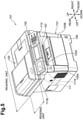
- FIG. 8 A perspective view of an ink jet printer according to the fifth illustrative embodiment is shown in FIG. 8 . It is to be noted that upward, downward, leftward, rightward, forward and backward directions are defined in an installation state illustrated in FIG. 8 in which the ink jet printer is used.
- the ink jet printer 1 is a recording apparatus and also an image forming apparatus and includes a printer housing 2 formed from a synthetic resin material and a cover 3 attached for pivotal motion to the printer housing 2.
- An opening is formed at a front portion of the printer housing 2 and surrounded by an upper wall 2a, side walls 2b and 2c and a bottom wall 2d of the printer housing 2.
- a control board 29 is disposed in a horizontal posture on an upper face of the upper wall 2a. In the control board 29, various circuits for controlling the ink jet printer 1 are incorporated. In FIG. 11 , the upper wall 2a and the control board 29 are not shown.
- the printer housing 2 accommodates a printer unit or recording unit 4 for recording an image and so forth on a recording paper sheet 100 which is recording medium, and a feeding mechanism 5 for feeding the recording paper sheet 100 to the printer unit 4.
- the printer housing 2 further accommodates a discharge unit 6 into which the recording paper sheet 100 recorded by the printer unit 4 is discharged.
- the printer housing 2 further accommodates a maintenance unit 7 for carrying out maintenance of an ink jet head 18 of the printer unit 4, and a scanner unit 8 for reading an image, characters and so forth recorded on the recording paper sheet 100.
- An operation panel 9 for accepting various operations for the ink jet printer 1 by a user is disposed at a front portion of an upper face of the printer housing 2. It is to be noted that a configuration of the components is hereinafter described.
- an opening and closing lid 10 is attached to the right end of a front face of the printer housing 2, and a holder 12 on which ink cartridges 11 are to be mounted is disposed behind the opening and closing lid 10.
- the holder 12 has four cartridge mounting portions 12a, into which four ink cartridges 11 in which inks of four colors, namely, cyan (C), magenta (M), yellow (Y) and black (BK, are stored individually, are removably mounted from the front.
- the cover 3 is disposed behind the operation panel 9 of the printer housing 2 and above the printer housing 2 in such a manner as to cover the upper face of the printer housing 2. Further, the cover 3 is attached to the printer housing 2 through a pivot shaft not shown provided at a rear end portion thereof such that it can be pivoted upwardly and downwardly with respect to the printer housing 2 around the pivot shaft.
- the feeding mechanism 5 includes a paper cassette 15 mounted on the printer housing 2, and a pickup roller 16 for picking up a recording paper sheet 100 from the paper cassette 15.
- the paper cassette 15 has a main tray 15a for holding the recording paper sheets 100 in a stacked state thereon and a discharge tray 15b provided above the main tray 15a for receiving the recording paper sheet 100 recorded by and discharged from the printer unit 4 hereinafter described.
- the pickup roller 16 is disposed above the main tray 15a and configured to rotate around a rotatable shaft provided on the printer housing 2.
- the pickup roller 16 is driven to rotate by a paper feed motor 80 shown in FIG. 13 to pick up the recording paper sheets 100 one by one from the main tray 15a of the paper cassette 15.
- the recording paper sheet 100 picked up by the pickup roller 16 is pushed upwardly along an inclined face 15c provided at an end portion of the paper cassette 15 and supplied to the printer unit 4.
- the printer unit 4 is disposed in the printer housing 2 and carries out recording on a recording paper sheet 100.
- the printer unit 4 is disposed above the feeding mechanism 5.
- the printer unit 4 includes a carriage 17 mounted for back and forth movement in the leftward and rightward direction, namely, in a scanning direction, and an ink jet head 18 carried on the carriage 17.
- the printer unit 4 further includes a transport mechanism 19 for transporting a recording paper sheet 100 forwardly, namely, in a discharging direction, along a horizontal plane.
- a platen 20 for supporting a recording paper sheet 100 is disposed in a horizontal posture.
- Two guide rails 21 and 22 are provided above the platen 20 and extend in parallel to each other in the scanning direction.
- the carriage 17 is driven by a carriage driving motor 78 shown in FIG. 13 to move in the scanning direction, namely, in the leftward and rightward direction, along the two guide rails 21 and 22 in a region opposing the recording paper sheet 100 on the platen 20.
- the ink jet head 18 is attached to a lower portion of the carriage 17 in a state in which a gap is provided between the ink jet head 18 and the platen 20.
- a lower face of the ink jet head 18 serves as an ink drop injection face 18a to which a plurality of nozzles 23 are opened.
- the nozzles 23 are arrayed along the discharging direction to configure four nozzle columns for injecting inks of the four colors, namely, of cyan, magenta, yellow and block.
- the ink jet head 18 carried on the carriage 17 is connected to the holder 12 described hereinabove through tubes not shown such that the inks of the four colors stored in the four ink cartridges 11 mounted on the holder 12 are supplied to the ink jet head 18 through the tubes.
- the ink jet head 18 is movable together with the carriage 17 not only within a range within which it is opposed to a recording paper sheet 100 transported on the platen 20 but also to positions displaced to the left and right outer sides from the range. Particularly, the position on the right side with respect to the opposing range to the recording paper sheet 100 is a standby position at which the carriage 17 stands by when the ink jet head 18 is not used. When the carriage 17 arrives at the standby position, it opposes the maintenance unit 7 hereinafter described which is disposed below the carriage 17.
- the transport mechanism 19 includes two transport roller pairs 24 and 25 disposed forward and rearward in such a manner that the platen 20 and the carriage 17 are positioned therebetween.
- the transport roller pairs 24 and 25 are driven by a transport motor 79 shown in FIG. 13 to transport a recording paper sheet 100 forwardly, namely, in the discharging direction, between the ink jet head 18 and the platen 20.
- ink is injected from the ink jet head 18 to a recording paper sheet 100 on the platen 20 and the recording paper sheet 100 is transported in the discharging direction by the two transport roller pairs 24 and 25 to record a desired image or characters on the recording paper sheet 100.
- the above-described opening surrounded by the upper wall 2a, side walls 2b and 2c and bottom wall 2d is formed below the operation panel 9 at a front portion of the printer housing 2.
- the paper cassette 15 is mounted on the bottom wall 2d under the opening.
- the paper cassette 15 is removable from the printer housing 2.
- the discharge unit 6 is formed from the discharge tray 15b, namely, a discharge face of the discharge tray 15b, at the top of the paper cassette 15, and an opening region above the paper cassette 15 surrounded by the discharge tray 15b and the upper wall 2a and side walls 2b and 2c of the printer housing 2.
- a recording paper sheet 100 recorded by the printer unit 4 is transferred forwardly by the transport roller pairs 24 and 25 and placed on the discharge tray 15b of the discharge unit 6. In this manner, the discharge unit 6 is formed in the printer housing 2, and the recording paper sheet 100 recorded by the printer unit 4 is discharged to the discharge unit 6. The user can take out the recording paper sheet 100 placed on the discharge tray 15b from the front of the discharge unit 6.
- the maintenance unit 7 is disposed at a position on the right side of the platen 20, namely, at a position opposing the ink jet head 18 when the ink jet head 18 stands by at the standby position.
- the maintenance unit 7 includes a cap member 26 which closely contacts with the ink drop injection face 18a of the ink jet head 18 to cover the openings of the nozzles 23.
- the maintenance unit 7 further includes a suction pump 27 for compulsorily discharging ink from the nozzles 23 covered with the cap member 26 to the cap member 26, a wiper 28 for wiping off the ink sticking to the ink drop injection face 18a, and so forth.
- the scanner unit 8 includes a carriage 30 movable back and forth in the leftward and rightward direction, and an image scanner 31 carried on the carriage 30.
- a guide rail 32 is provided such that it extends in parallel to the scanning direction, namely, in the leftward and rightward direction.
- the carriage 30 is driven by a carriage driving motor not shown, it moves in the scanning direction, namely, in the leftward and rightward direction, along the guide rail 32 within a range opposing a plate member 14 fitted in an opening 13 in the printer housing 2.
- the recording paper sheet 100 is scanned by the image scanner 31.
- the ink jet printer 1 of the present illustrative embodiment is configured as a composite machine which can execute printing, scanning, copying and so forth.
- the operation panel 9 is provided at a front portion of an upper face of the printer housing 2 and above the discharge unit 6, and has various operation buttons 33 to 36, a liquid crystal display unit 37 of the touch panel type, and so forth.
- the liquid crystal display unit 37 displays various kinds of information thereon, and the user can operate the liquid crystal display unit 37 to instruct the ink jet printer 1 to carry out various operations.
- a large number of conductors for the liquid crystal display unit 37 and so forth are disposed on the operation panel 9.
- a panel controlling board 38 for controlling the operation panel 9 is provided below the operation panel 9 as shown in FIG. 10 .
- a panel controlling circuit 81 shown in FIG. 13 for controlling the operation panel 9 and associated elements is incorporated in the panel controlling board 38.
- the ink jet printer 1 carries out communication by the NFC (Near Field Communication), which is a type of short-range wireless communication, with a communication terminal 200 such as a portable telephone set or a smartphone. Consequently, the ink jet printer 1 can receive recording data of an image or characters from the communication terminal 200.
- NFC Near Field Communication
- the ink jet printer 1 can receive recording data of an image or characters from the communication terminal 200.
- a configuration of the ink jet printer 1 which relates to the short-range wireless communication is described.
- a terminal receiving member 39 on which the communication terminal 200 can be placed is provided in the discharge unit 6.
- the terminal receiving member 39 is a recessed portion provided on the discharge tray 15b on which a recording paper sheet 100 recorded by the printer unit 4 is to be placed as shown also in FIG. 12 .
- the terminal receiving member 39 is formed in a substantially rectangular shape at a central portion at a front end portion of the discharge tray 15b.
- the terminal receiving member 39 has an extent sufficient to accommodate the communication terminal 200 therein and has a depth with which the communication terminal 200 does not project upwardly from the terminal receiving member 39 in a state in which the communication terminal 200 is mounted in the terminal receiving member 39.
- the user can place the communication terminal 200 readily into the terminal receiving member 39 from the front of the discharge unit 6.
- a mark 40 which indicates the position of the terminal receiving member 39 and is, in the present illustrative embodiment, an arrow mark, is applied.
- an antenna 41 serving as a communication unit may communicate by the NFC with the communication terminal 200 received in the terminal receiving member 39.
- the antenna 41 is a loop antenna and is disposed on a lower face, namely, the reverse face, of the panel controlling board 38. Further, the antenna 41 is disposed on a lower face of the panel controlling board 38 disposed in a substantially horizontal posture such that the loop portion thereof lies substantially in parallel to the horizontal direction. Further, the antenna 41 is disposed substantially directly above the terminal receiving member 39 such that the distance L between the terminal receiving member 39 and the antenna 41 is within 10 cm which is a maximum communication distance by the NFC.
- Another loop antenna not shown is built in the communication terminal 200 such that the loop portion thereof extends in parallel to a direction perpendicular to the thickness direction of the communication terminal 200. Therefore, if the communication terminal 200 is installed on the horizontal bottom face of the terminal receiving member 39, then the loop portions of the antenna 41 of the ink jet printer 1 and the antenna of the communication terminal 200 oppose substantially in parallel to each other.
- the communication terminal 200 is received in the terminal receiving member 39, then communication by NFC is carried out between the antenna 41 on the ink jet printer 1 side and the antenna on the communication terminal 200 side. More particularly, if a magnetic field is generated from one of the loop antenna 41 of the ink jet printer 1 side and the loop antenna of the communication terminal 200 side, then induced current is generated in the other antenna by electromagnetic induction. Consequently, data is transmitted from the one antenna to and received by the other antenna. Then, if the transmission (magnetic field generation) function and the reception (induced current generation) function of both antennae are changed over alternately, then bidirectional communication can be achieved between the ink jet printer 1 and the communication terminal 200.
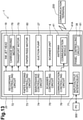
- FIG. 13 is a block diagram schematically showing an electric configuration of the ink jet printer 1.
- the control board 29 for controlling operation of the ink jet printer 1 is connected for data communication with a PC (personal computer) 300, which is an external apparatus, through an input/output interface (I/F) 71 such that recording data of an image or characters to be recorded are inputted from the PC 300 to the control board 29.
- the panel controlling board 38 in which the panel controlling circuit 81 is incorporated is connected to the control board 29 such that various operations from the operation panel 9 are inputted as various signals relating to operation of the ink jet printer 1 to the control board 29 through the panel controlling circuit 81.
- a recording controlling circuit 72 for controlling recording operation of the printer unit 4, which includes the ink jet head 18 and so forth, based on received recording data, and a paper feeding controlling circuit 73 for controlling paper feeding operation by the feeding mechanism 5 are incorporated.
- a maintenance controlling circuit 74 for controlling maintenance operation by the maintenance unit 7 a scanner controlling circuit 75 for controlling scanning of a recording paper sheet by the scanner unit 8 and a communication controlling circuit 76 for controlling data communication by the NFC with the communication terminal 200 are incorporated.
- the communication controlling circuit 76 is connected to a communication module 41a of the antenna 41.
- communication with the communication terminal 200 by NFC is started by the user operating the liquid crystal display unit 37 of the operation panel 9 to input a predetermined instruction.
- the communication controlling circuit 76 carries out communication with the communication terminal 200. At this time, if the communication terminal 200 is placed into the terminal receiving member 39 by the user and then the communication with the communication terminal 200 is carried out normally, then the reception of the recording data is completed.
- the ink jet printer 1 includes a printer housing 2, a printer unit 4 disposed in the printer housing 2 for carrying out recording on a recording paper sheet 100, a discharge unit 6 formed in the printer housing 2 for receiving the recording paper sheet 100 recorded by the printer unit 4 and discharged thereto, a terminal receiving member 39 provided on the discharge unit 6 for receiving a communication terminal 200 placed therein, and an antenna 41 for communicating with the communication terminal 200 placed in the terminal receiving member 39 by short-range wireless communication.
- the terminal receiving member 39 in which the communication terminal 200 can be received is provided on the discharge unit 6 to which a recording paper sheet 100 is discharged.
- the discharge unit 6 receives the recording paper sheet 100 discharged thereto and has a large opening to this side, namely, to the user side, so that the user can take out the discharged recording paper sheet 100 therethrough. Accordingly, it is easy for the user to place the communication terminal 200 into such a discharge unit 6 as just described.
- the terminal receiving member 39 is provided on the discharge unit 6, a vacant space can be utilized effectively and a receiving space for the communication terminal 200 can be assured without increasing the size of the apparatus.
- the communication terminal 200 since the communication terminal 200 is received in the discharge unit 6 which has a large opening, the communication terminal 200 can be visually recognized readily by the user, and the communication terminal 200 can be prevented from being left in the terminal receiving member 39.
- the terminal receiving member 39 is provided on the discharge tray 15b of the discharge unit 6 on which a recording paper sheet 100 recorded by the printer unit 4 is to be placed, the user can place the communication terminal 200 readily into the terminal receiving member 39.
- the terminal receiving member 39 is a recessed portion formed on the discharge tray 15b of the discharge unit 6 and capable of accommodating the communication terminal 200 therein, the communication terminal 200 is accommodated into the recessed portion formed on the discharge tray 15b of the discharge unit 6. Consequently, when a recording paper sheet 100 is discharged, it is less likely to contact the communication terminal 200.
- the operation panel 9 and the panel controlling board 38 for controlling the operation panel 9 are disposed above the discharge unit 6 and the antenna 41 is disposed on the panel controlling board 38. Therefore, communication between the communication terminal 200 and the antenna 41 can be carried out reliably.
- the panel controlling board 38 is positioned on the reverse side of the operation panel 9. Namely, the operation panel 9 is positioned on the opposite side to the communication terminal 200 across the panel controlling board 38. Accordingly, wireless communication between the antenna 41 provided on the panel controlling board 38 and the communication terminal 200 is not obstructed by the operation panel 9 which includes a large number of conductors.
- the mark 40 indicating the position of the terminal receiving member 39 may be applied, the user can readily recognize the place at which the communication terminal 200 is to be placed.
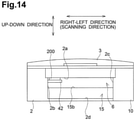
- a terminal receiving member 42 is provided at a position spaced from the discharge tray 15b of the discharge unit 6 as shown in FIG. 14 .
- the terminal receiving member 42 is a table provided on the discharge unit 6 and extending horizontally from the side wall 2b of the printer housing 2 above the discharge tray 15b such that the communication terminal 200 can be placed on the table.
- the communication terminal 200 is placed at a position spaced from the discharge tray 15b of the discharge unit 6. Consequently, a recording paper sheet 100 discharged along the discharge tray 15b is less likely to contact the communication terminal 200.
- the distance of the communication terminal 200 to the antenna 41 provided on the panel controlling board 38 is reduced in comparison with the fifth illustrative embodiment described above, wireless communication between the antenna 41 and the communication terminal 200 is enhanced.
- a terminal receiving member 43 is a groove which is formed in a region of the discharge tray 15b of the discharge unit 6 on the end side in the widthwise direction of a recording paper sheet 100 perpendicular to the discharging direction of the recording paper sheet 100 and extends in the discharging direction of the recording paper sheet 100 as shown in FIGS. 15 and 16 .
- the antenna 41 is provided in parallel to the terminal receiving member 43.
- the antenna 41 can be provided in parallel to the terminal receiving member 43 on a cartridge controlling board not shown, in which a cartridge controlling circuit not shown for controlling the ink cartridges 11 is incorporated, or on a side face of the printer housing 2.
- the communication terminal 200 of a flattened shape is inserted into the groove formed at the end portion of the discharge unit 6 in a state in which the communication terminal 200 stands uprightly, then the communication terminal 200 can be disposed along an inner side face of the discharge unit 6. Accordingly, a discharged recording paper sheet 100 is less likely to contact the communication terminal 200.
- an upper face of an auxiliary tray 44 serves as a terminal receiving member 45 by which the communication terminal 200 is received as shown in FIG. 17 .
- the auxiliary tray 44 can move out from the discharge tray 15b of the discharge unit 6 to the discharging side of a recording paper sheet 100.
- the auxiliary tray 44 is attached to the discharge tray 15b through a pivot shaft not shown provided at a rear end portion thereof such that it is pivoted around the pivot shaft to move out to the discharging side of a recording paper 100 from the discharge tray 15b.
- the antenna 41 is provided on the auxiliary tray 44.
- the auxiliary tray 44 since the upper face of the auxiliary tray 44 is the terminal receiving member 45 by which the communication terminal 200 is to be received, when the communication terminal 200 is mounted on the auxiliary tray 44 moved out from the discharge unit 6, a recording paper sheet 100 discharged from the discharge unit 6 is prevented with a higher degree of certainty from moving out by the communication terminal 200. Further, since the antenna 41 is provided on the auxiliary tray 44, the distance between the communication terminal 200 provided on the auxiliary tray 44 and the antenna 41 is very short, and consequently, wireless communication between them can be carried out reliable. While the auxiliary tray 44 in the present modification is provided for pivotal motion on the discharge tray 15b, it may otherwise be provided for sliding movement on the discharge tray 15b such that it can be drawn out forwardly.
- the terminal receiving member 45 may otherwise be provided on an upper face of the main tray 15a in the inside of the paper cassette 15. In this instance, the antenna 41 is provided on the main tray 15a.
- the antenna 41 is connected to the communication module 41a, it can be provided on a board, in the fifth illustrative embodiment described hereinabove, on the panel controlling board 38.
- the antenna 41 is provided on an ink cartridge board as in the modification described hereinabove or on the control board 29.
- the terminal receiving member 45 may be provided on the discharge tray 15b below the antenna 41.
- NFC is applied to carry out short-range wireless communication between the ink jet printer 1 and the communication terminal 200
- RFID Radio Frequency Identification
- the communication terminal is not limited to a portable telephone set, a smartphone or the like but may be an IC (Integrated Circuit) card, an IC tag or the like.
- the data communicated by the short-range wireless communication is not limited to recording data but may be data such as log-in information to an ink jet printer.
- the paper cassette 15 and the discharge tray 15b may not be formed as a unitary member but may be provided at positions spaced from each other while the upper face of the paper cassette 15 does not serve as the discharge tray 15b.
- an image forming apparatus comprises a housing, an image forming unit, a discharge tray, a terminal receiving member, and an antenna.
- the image forming unit disposed in the housing and configured to form an image on a sheet.
- the discharge tray disposed in the housing and configured to receive the sheet on which an image is formed by the image forming unit.
- the terminal receiving member disposed on the discharge tray and configured to receive a communication terminal thereon.
- the antenna configured to communicate with the communication terminal received on the terminal receiving member by short-range wireless communication.
- the terminal receiving member is a recessed portion formed on the discharge tray and configured to hold the communication terminal therein.
- the terminal receiving member is a groove formed at a side of the discharge tray, the groove extending along a discharging direction in which a sheet is discharged from the image forming unit.
- an operation unit and a panel controlling board configured to control the operation unit are disposed above the discharge tray, and the antenna is disposed on the panel controlling board.
- the discharge tray comprises an auxiliary tray configured to extend from the discharge tray in a discharging direction in which a sheet is discharged from the image forming unit, and the terminal receive member is located on a surface of the auxiliary tray, wherein the surface is the upper face of the auxiliary tray when the auxiliary tray is extended.
- an indicator identifying a position of the terminal receiving member is disposed on a discharge unit.
- an image forming apparatus comprises a housing, an image forming unit, a discharge tray, a terminal receiving member, and an antenna.
- the image forming unit is disposed in the housing and configured to form an image on a sheet.
- the discharge tray is disposed in the housing and configured to receive the sheet on which an image is formed by the image forming unit.
- the terminal receiving member is disposed in and coupled to the housing and configured to receive a communication terminal thereon and is disposed at a position spaced away from and overlapping the discharge tray.
- the antenna is configured to communicate with the communication terminal received on the terminal receiving member by short-range wireless communication.
- the ink jet printer 1 in the fifth illustrative embodiment described above is a recording apparatus of the ink jet type
- the recording method is not limited to the ink jet type but may be that of a laser type, an LED (Light Emitting Diode) type or the like.
- the recording method is that of the ink jet type
- an ink jet method of a line type may be applied.
Description
- Aspects of the present disclosure relate to an image forming apparatus which includes an antenna portion for short range wireless communication.
- A known image forming apparatus includes short-range wireless communication function which may be carried out between an image forming apparatus and a portable apparatus. The term "short range wireless communication" used herein is intended to signify wireless communication within a maximum range of, for example, 1 meter.
-
JP 2005 22 7712 A -
US 2009/0184817 A1 discloses an image forming apparatus is supplied capable of improving distance precision and relative position precision of RFID tag and RFID unit so as to heighten communication quality of image forming apparatus. The image forming apparatus comprises attachable and removable exchange cartridge which is used for accommodating toner and has a RFID tag, and RFID unit that communicates with the RFID tag through radio communication, wherein the exchange cartridge is furnished as retreating in non-operational time; the exposure head unit is furnished movably; in the case that the exchange cartridge retreats, the exposure head unit moves together with the exchange cartridge. -
EP 1 182 520 A2 discloses a memory member usable with an electrophotographic image forming apparatus, includes a base; a storing element, provided in the base, for storing information; a memory antenna, provided in the base, for sending the information stored in the storing element to a main assembly antenna provided in a main assembly of the apparatus, when the memory member is mounted to the main assembly of the electrophotographic image forming apparatus; a sending member, provided in the base, for sending the information stored in the storing element to the memory antenna; and an outer casing member covering the base provided with the storing element, the sending member and the memory antenna. - However, if an antenna portion used for short-range wireless communication is disposed at an inappropriate position, then the operability of the image forming apparatus which utilizes a communication device such as a portable device degrades.
- Therefore, it is desirable to provide an image forming apparatus which utilizes a communication device and is improved in operability.
-
-
FIG. 1 is a perspective view showing an appearance of an image forming apparatus according to a first illustrative embodiment. -
FIG. 2 is a central sectional view of the image forming apparatus ofFIG. 1 . -
FIG. 3 is a projection view of the image forming apparatus ofFIG. 1 to a horizontal plane. -
FIG. 4 is a perspective view showing an appearance of an image forming apparatus according to a second illustrative embodiment. -
FIG. 5 is a perspective view showing an appearance of an image forming apparatus according to a third illustrative embodiment. -
FIG. 6 is a partial perspective view showing a modification to the image forming apparatus ofFIG. 5 . -
FIG. 7 is a perspective view showing an appearance of an image forming apparatus according to a fourth illustrative embodiment; -
FIG. 8 is a perspective view showing an appearance of an ink jet printer according to a fifth illustrative embodiment. -
FIG. 9 is a front view of the ink jet printer ofFIG. 8 . -
FIG. 10 is a sectional view taken along line I-I ofFIG. 9 . -
FIG. 11 is a sectional view taken along line II-II ofFIG. 10 . -
FIG. 12 is a perspective view of a paper cassette. -
FIG. 13 is a block diagram schematically showing an electric configuration of the ink jet printer ofFIG. 8 . -
FIGS. 14 and15 are front views of ink jet printers having different modified forms of a terminal receiving member. -
FIGS. 16 and17 are perspective views of further different modified forms of the terminal receiving member. - Hereinafter, one or more aspects of the disclosure are described.
- An image forming apparatus 1 according to an illustrative embodiment, illustrated in
Fig. 1 , is one practical example of an image forming apparatus according to aspects of the present disclosure. In short, the matters specifying the claimed invention are not limited to particular members, structures or the like exemplified by the following illustrative embodiments. In the following, the illustrative embodiments are described with reference to the drawings. - Referring first to
FIG. 1 , ahousing 103 of animage forming apparatus 101 according to the present illustrative embodiment configures a design surface appearance of theimage forming apparatus 101. In the apparatus main body, namely, in thehousing 103, animage forming unit 105 for forming an image on a sheet such as a paper sheet is accommodated as shown inFIG. 2 . - It is to be noted that the
image forming unit 105 in the present illustrative embodiment is an image forming unit of the monochromatic type or an image forming member of the xerographic type having aphotosensitive member 105A, acharger 105B, anexposure unit 105C, atransfer member 105D, afixing unit 105E and so forth. - The
photosensitive member 105A carries a developer image thereon. Thecharger 105B charges thephotosensitive member 105A. Theexposure unit 105C exposes the surface of the chargedphotosensitive member 105A to form an electrostatic latent image on the surface of thephotosensitive member 105A. Then, if charged developer is supplied to thephotosensitive member 105A on which the electrostatic latent image is formed, then a developer image is carried on the surface of thephotosensitive member 105A. - The
transfer member 105D is configured to transfer the developer image carried on thephotosensitive member 105A to a sheet and is disposed at a position opposing to thephotosensitive member 105A. Thefixing unit 105E fixes the developer image transferred to the sheet. It is to be noted that thefixing unit 105E in the present illustrative embodiment is a fixing device of the heating type which heats the developer to deposit the developer onto the sheet. - Then, the sheet for which image formation is completed is discharged from a
discharge port 107A to adischarge tray 107. It is to be noted that thedischarge port 107A in the present illustrative embodiment is open to the forward side at a rearward side upper portion of thehousing 103. Thedischarge tray 107 is configured to have an inclined face which is inclined downward toward thedischarge port 107A. - Below the
image forming unit 105 in thehousing 103, afeed tray 109 is disposed which has a receivingportion 109A on which a plurality of sheets can be placed. Thefeed tray 109 is removably mounted on the apparatus main body, namely, on thehousing 103. In the present illustrative embodiment, thefeed tray 109 may be mounted on and removed from thehousing 103 by moving thefeed tray 109 in forward and backward directions. - Sheets placed in a stacked state on the
feed tray 109 are successively fed to theimage forming unit 105 from the upper end side of thefeed tray 109 in the stacking direction. - In the
housing 103, acommunication board 111 having anantenna portion 111A for short-range wireless communication is disposed as shown inFIG. 2 . Further, theimage forming apparatus 101 according to the present illustrative embodiment carries out short-range wireless communication with a communication device such as a portable apparatus (not shown) through theantenna portion 111A. By such short-range wireless communication, for example, the following acts can be carried out. - In particular, (a) the
image forming apparatus 101 can be operated through an operation unit of the communication device. (b) Image data to be formed on a sheet can be transmitted from the communication device to theimage forming apparatus 101 directly without passing through a computer or the like so that it is printed by theimage forming apparatus 101. Or, (c) by authenticating an owner of the communication device, an operation permitted in advance to the owner is executed while operations other than the permitted operation are prohibited. - A
communication unit 111B which corresponds to theantenna portion 111A is provided at a position on the outer surface of thehousing 103 at which thecommunication unit 111B may be seen without obstruction from the upper side as shown inFIG. 1 . - In particular, the
image forming apparatus 101 does not have any portion above thecommunication unit 111B. Therefore, in a region from above thecommunication unit 111B to thecommunication unit 111B, nothing blocks the field of vision of the user, and the user may see thecommunication unit 111B without obstruction from the upper side. - In particular, the
communication unit 111B is provided on an upper face of a forward side of thehousing 103. Anoperation region 113 which is operated by a user is provided on the front side of thehousing 103. In particular, thecommunication unit 111B in the present illustrative embodiment is provided, at least in the forward and backward direction of thehousing 103, on the same side as theoperation region 113. - More particularly, the
communication unit 111B is provided at a position displaced toward the front side with respect to thedischarge tray 107 in the forward and backward direction of thehousing 103. It is to be noted that the "front face side in the forward and backward direction of thehousing 103" is a side of thehousing 103 on which theoperation region 113 is provided, for example, with respect to the center in the forward and backward direction. - Therefore, if the
antenna portion 111A and thecharger 105B are projected to a horizontal plane, then theantenna portion 111A projected to the horizontal plane is displaced with respect to thecharger 105B projected to the horizontal plane. In other words, theantenna portion 111A projected to the horizontal plane is positioned on the opposite side to thefixing unit 105E projected to the horizontal plane across thecharger 105B projected to the horizontal plane. - Further, the
communication unit 111B is formed in a horizontally planar state as shown inFIG. 2 . It is to be noted that the term "horizontal" signifies a horizontal state of such a degree that, when a communication device is placed on thecommunication unit 111B, the communication device does not slip down from thecommunication unit 111B, namely, from thehousing 103. Further, the term "planar state" signifies a planar state of such a degree that, when a communication device is placed on thecommunication unit 111B, the communication device does not suffer from any significant rattle. - Further, an opening 103A and a
front cover 103B are provided on the forward side of thehousing 103. The opening 103A establishes communication between the inside and the outside of thehousing 103. Thefront cover 103B is assembled to thehousing 103 for displacement between a position at which thefront cover 103B closes the opening 103A and a position at which thefront cover 103B opens the opening 103A. It is to be noted that thefront cover 103B in the present illustrative embodiment opens and closes the opening 103A by rocking displacement thereof around a lower end side thereof. - The
antenna portion 111A is disposed on the upper side with respect to an upper end of thefront cover 103B. In other words, theantenna portion 111A is positioned at a location displaced to the outer side from an outer edge of the opening 103A as viewed from the opening direction of the opening 103A, in the present illustrative embodiment, from the forward and backward direction. - It is to be noted that the opening 103A can allow a dismounting or mounting operation of a
process unit 105F or a removing operation of a jamming sheet or the like to be carried out. Incidentally, theprocess unit 105F is a casing in which thephotosensitive member 105A, developer and so forth can be accommodated. - In the present illustrative embodiment, since the
communication unit 111B is provided at a position at which it can be seen without obstruction from the upper side, a communication device such as a smartphone can be brought close to or into contact with thecommunication unit 111B readily. Accordingly, since wireless communication between theantenna portion 111A and a communication device can be established reliably, the operability of the image forming apparatus which utilizes the communication device can be improved. - In the present illustrative embodiment, the
antenna portion 111A is disposed such that theantenna portion 111A projected to the horizontal plane is displaced from thecharger 105B projected to the horizontal plane. Therefore, the distance between theantenna portion 111A and thecharger 105B may be made comparatively great. Accordingly, a situation in which theantenna portion 111A suffers from electric noise from thecharger 105B may be suppressed. - In the present illustrative embodiment, the
antenna portion 111A is disposed such that theantenna portion 111A projected to the horizontal plane is positioned on the opposite side to thefixing unit 105E projected to the horizontal plane across thecharger 105B projected to the horizontal plane. Therefore, theantenna portion 111A can be spaced from the fixingunit 105E. Accordingly, where the fixingunit 105E of the heating type is adopted, theantenna portion 111A can be protected against the heat of the fixingunit 105E. - In the present illustrative embodiment, since the
communication unit 111B is provided at a position displaced from thedischarge tray 107, such a failure that a sheet placed on thedischarge tray 107 makes an obstacle when a communication device is brought close to or into contact with thecommunication unit 111B can be prevented. - In the present illustrative embodiment, since the
communication unit 111B is positioned on the upper face of the forward side of thehousing 103, the user can bring a communication device close to or into contact with thecommunication unit 111B readily. - In the present illustrative embodiment, since the
communication unit 111B is formed so as to have a horizontal planar shape, a communication device may be layed down stablewhen it is placed on thecommunication unit 111B. Accordingly, the user need not hold the communication device, and consequently, the image forming apparatus is improved in convenience in use. - In the present illustrative embodiment, since the
antenna portion 111A is disposed on the upper side with respect to an upper end of thefront cover 103B, the user can bring a communication device close to or into contact with thecommunication unit 111B readily, independent of the position of thefront cover 103B. - In particular, if the
communication unit 111B is provided otherwise on a movable member such as thefront cover 103B, then since the position of thecommunication unit 111B is displaced depending upon the state of the movable member, it is difficult to bring a communication device close to or into contact with thecommunication unit 111B. - The
communication unit 111B in the first illustrative embodiment is provided at a position displaced forwardly with respect to thedischarge tray 107 in the forward and backward direction of thehousing 103. However, in the present illustrative embodiment, thecommunication unit 111B is provided at a position displaced with respect to thedischarge tray 107 in the leftward and rightward direction of thehousing 103 as shown inFIG. 4 . - Further, the
communication unit 111B in the present illustrative embodiment is formed in an inclined planar shape which extends downwardly toward the forward side. Further, a holdingmember 111C for holding a communication device thereon is provided on the lower end side of thecommunication unit 111B. - It is to be noted that the inclined face of the
housing 103 which configures thecommunication unit 111B may have any configuration. For example, the inclined face of thehousing 103 may be formed integrally with atop cover 103C which configures thehousing 103 or may be formed as a separate member from thetop cover 103C and assembled to thetop cover 103C. - Further, the
communication unit 111B in the present illustrative embodiment is formed in an inclined planar shape which is inclined downwardly toward the forward side. Therefore, for example, where a display unit is provided on a communication device, the user can visually recognize the display unit readily while the communication device remains placed on thecommunication unit 111B. - Further, in the present illustrative embodiment, since the holding
member 111C for holding a communication device is provided on the lower end side of thecommunication unit 111B, the user need not continue to hold the communication device. Accordingly, the image forming apparatus can be improved in convenience in use. - It is to be noted that, while the
communication unit 111B inFIG. 4 is provided on the rear face side, namely, on the rearward side with respect to the center in the forward and backward direction, the present illustrative embodiment is not limited to this, but thecommunication unit 111B may be provided on the forward side. - Further, while, in
FIG. 4 , the holdingmember 111C is configured from a groove extending in the leftward and rightward direction, the present illustrative embodiment is not limited to this, but the holdingmember 111C may be configured, for example, from a projection which projects upwardly from thetop cover 103C or a like element. Or, a flat face of thetop cover 103C may be utilized as the holdingmember 111C, or else, the holdingmember 111C may be eliminated. - In the present illustrative embodiment depicted in
FIG. 5 , animage forming apparatus 101 with which areading unit 120 for reading in image information described on a manuscript is integrated is shown. - In particular, the
housing 103 in the present illustrative embodiment includes afirst housing member 131 and asecond housing member 132. Thefirst housing member 131 accommodates theimage forming unit 105 and corresponds to the housing in the first illustrative embodiment. - The
second housing member 132 accommodates thereading unit 120 therein and is positioned at a location spaced above thefirst housing member 131 with aspace 130A left therebetween. In short, thereading unit 120 is positioned at the location spaced above thedischarge tray 107 with thespace 130A therebetween. - Further, at a position of the
second housing member 132 displaced from thereading unit 120, anoperation panel 132A which configures part of thesecond housing member 132 and has theoperation region 113 is provided. Thecommunication unit 111B is provided on theoperation panel 132A. - Accordingly, if the
reading unit 120 and theantenna portion 111A are projected to a horizontal plane, then theantenna portion 111A projected to the horizontal plane is displaced from thereading unit 120 projected to the horizontal plane. Particularly, in the present illustrative embodiment, theoperation panel 132A is displaced frontward with respect to thereading unit 120 and is provided at a position at which theoperation panel 132A can be seen from the upper side without obstruction. - Therefore, in the present illustrative embodiment, the user may bring a communication device close to or into contact with the
communication unit 111B readily without being obstructed by thereading unit 120. - Further, since the
communication unit 111B is provided on thesecond housing member 132 disposed on the upper side with respect to thefirst housing member 131, the user can bring a communication device close to or into contact with thecommunication unit 11 1B readily from the upper side. - Although the
communication unit 111B in the present illustrative embodiment is configured in an inclined planar shape similar to that in the second illustrative embodiment, the holdingmember 111C is not provided on thecommunication unit 111B as shown inFIG. 5 . However, the present illustrative embodiment is not limited to this, but the holdingmember 111C may be provided otherwise on the lower end side of thecommunication unit 111B or thecommunication unit 111B may otherwise be formed in a horizontal planar shape. - Further, where the holding
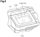
member 111C is provided, it may be configured such that, for example, as shown inFIG. 6 , a recessedportion 111D forms a recess in the upper face of theoperation panel 132A that allows a communication device to be received therein. If such a configuration as just described is adopted, then since a communication device can fit into the recessedportion 111D, the recessedportion 111D can function as the holdingmember 111C. - While, in the third illustrative embodiment, the
communication unit 111B is provided in thesecond housing member 132, in the present illustrative embodiment, thecommunication unit 111B is provided at a position of thefirst housing member 131 at which thecommunication unit 111B can be seen without obstruction from the upper side as shown inFIG. 7 . - Also in the present illustrative embodiment, if the
reading unit 120 and theantenna portion 111A are projected to a horizontal plane, then theantenna portion 111A projected to the horizontal plane is displaced with respect to thereading unit 120 projected to the horizontal plane. - Therefore, also in the present illustrative embodiment, the user may bring a communication device close to or into contact with the
communication unit 111B readily without being obstructed by thereading unit 120. - While the image forming units in the first to fourth illustrative embodiments described hereinabove are of the monochromatic xerography type, the present disclosure is not limited to this. In particular, the image forming unit may be of any type such as the color xerography type or the monochromatic or color ink jet type.
- Further, the particular utilization form of the short-range wireless communication is not limited to that used in the illustrative embodiments described hereinabove but may be any other utilization form.
- For example, a communication device having a display unit such as a liquid crystal panel may be used in such a utilization form that the display unit of the communication device functions as a display unit of the image forming apparatus through short-range wireless communication. Where the communication device is used as the display unit of the image forming apparatus, a configuration wherein the image forming apparatus does not have a display unit can be implemented. Therefore, reduction of the fabrication cost of the image forming apparatus can be anticipated.
- A perspective view of an ink jet printer according to the fifth illustrative embodiment is shown in
FIG. 8 . It is to be noted that upward, downward, leftward, rightward, forward and backward directions are defined in an installation state illustrated inFIG. 8 in which the ink jet printer is used. - Referring to
FIG. 8 , the ink jet printer 1 is a recording apparatus and also an image forming apparatus and includes aprinter housing 2 formed from a synthetic resin material and acover 3 attached for pivotal motion to theprinter housing 2. An opening is formed at a front portion of theprinter housing 2 and surrounded by anupper wall 2a,side walls bottom wall 2d of theprinter housing 2. As shown inFIG. 10 , acontrol board 29 is disposed in a horizontal posture on an upper face of theupper wall 2a. In thecontrol board 29, various circuits for controlling the ink jet printer 1 are incorporated. InFIG. 11 , theupper wall 2a and thecontrol board 29 are not shown. - Referring to
FIGS. 10 and11 , theprinter housing 2 accommodates a printer unit orrecording unit 4 for recording an image and so forth on arecording paper sheet 100 which is recording medium, and afeeding mechanism 5 for feeding therecording paper sheet 100 to theprinter unit 4. Theprinter housing 2 further accommodates adischarge unit 6 into which therecording paper sheet 100 recorded by theprinter unit 4 is discharged. Theprinter housing 2 further accommodates a maintenance unit 7 for carrying out maintenance of anink jet head 18 of theprinter unit 4, and ascanner unit 8 for reading an image, characters and so forth recorded on therecording paper sheet 100. Anoperation panel 9 for accepting various operations for the ink jet printer 1 by a user is disposed at a front portion of an upper face of theprinter housing 2. It is to be noted that a configuration of the components is hereinafter described. - Referring to
FIGS. 8 and11 , an opening and closinglid 10 is attached to the right end of a front face of theprinter housing 2, and aholder 12 on whichink cartridges 11 are to be mounted is disposed behind the opening and closinglid 10. Theholder 12 has fourcartridge mounting portions 12a, into which fourink cartridges 11 in which inks of four colors, namely, cyan (C), magenta (M), yellow (Y) and black (BK, are stored individually, are removably mounted from the front. - Referring to
FIG. 8 , thecover 3 is disposed behind theoperation panel 9 of theprinter housing 2 and above theprinter housing 2 in such a manner as to cover the upper face of theprinter housing 2. Further, thecover 3 is attached to theprinter housing 2 through a pivot shaft not shown provided at a rear end portion thereof such that it can be pivoted upwardly and downwardly with respect to theprinter housing 2 around the pivot shaft. - Referring to
FIG. 10 , thefeeding mechanism 5 includes apaper cassette 15 mounted on theprinter housing 2, and apickup roller 16 for picking up arecording paper sheet 100 from thepaper cassette 15. Thepaper cassette 15 has amain tray 15a for holding therecording paper sheets 100 in a stacked state thereon and adischarge tray 15b provided above themain tray 15a for receiving therecording paper sheet 100 recorded by and discharged from theprinter unit 4 hereinafter described. Thepickup roller 16 is disposed above themain tray 15a and configured to rotate around a rotatable shaft provided on theprinter housing 2. Thepickup roller 16 is driven to rotate by apaper feed motor 80 shown inFIG. 13 to pick up therecording paper sheets 100 one by one from themain tray 15a of thepaper cassette 15. Therecording paper sheet 100 picked up by thepickup roller 16 is pushed upwardly along aninclined face 15c provided at an end portion of thepaper cassette 15 and supplied to theprinter unit 4. - Referring to
FIGS. 10 and11 , theprinter unit 4 is disposed in theprinter housing 2 and carries out recording on arecording paper sheet 100. Theprinter unit 4 is disposed above thefeeding mechanism 5. Theprinter unit 4 includes acarriage 17 mounted for back and forth movement in the leftward and rightward direction, namely, in a scanning direction, and anink jet head 18 carried on thecarriage 17. Theprinter unit 4 further includes atransport mechanism 19 for transporting arecording paper sheet 100 forwardly, namely, in a discharging direction, along a horizontal plane. - In the
printer housing 2, aplaten 20 for supporting arecording paper sheet 100 is disposed in a horizontal posture. Twoguide rails platen 20 and extend in parallel to each other in the scanning direction. Thecarriage 17 is driven by acarriage driving motor 78 shown inFIG. 13 to move in the scanning direction, namely, in the leftward and rightward direction, along the twoguide rails recording paper sheet 100 on theplaten 20. - The
ink jet head 18 is attached to a lower portion of thecarriage 17 in a state in which a gap is provided between theink jet head 18 and theplaten 20. A lower face of theink jet head 18 serves as an ink drop injection face 18a to which a plurality ofnozzles 23 are opened. Thenozzles 23 are arrayed along the discharging direction to configure four nozzle columns for injecting inks of the four colors, namely, of cyan, magenta, yellow and block. Theink jet head 18 carried on thecarriage 17 is connected to theholder 12 described hereinabove through tubes not shown such that the inks of the four colors stored in the fourink cartridges 11 mounted on theholder 12 are supplied to theink jet head 18 through the tubes. - The
ink jet head 18 is movable together with thecarriage 17 not only within a range within which it is opposed to arecording paper sheet 100 transported on theplaten 20 but also to positions displaced to the left and right outer sides from the range. Particularly, the position on the right side with respect to the opposing range to therecording paper sheet 100 is a standby position at which thecarriage 17 stands by when theink jet head 18 is not used. When thecarriage 17 arrives at the standby position, it opposes the maintenance unit 7 hereinafter described which is disposed below thecarriage 17. - The
transport mechanism 19 includes two transport roller pairs 24 and 25 disposed forward and rearward in such a manner that theplaten 20 and thecarriage 17 are positioned therebetween. The transport roller pairs 24 and 25 are driven by atransport motor 79 shown inFIG. 13 to transport arecording paper sheet 100 forwardly, namely, in the discharging direction, between theink jet head 18 and theplaten 20. - In the
printer unit 4 described above, while thecarriage 17 is moved in the scanning direction, namely, in the leftward and rightward direction, ink is injected from theink jet head 18 to arecording paper sheet 100 on theplaten 20 and therecording paper sheet 100 is transported in the discharging direction by the two transport roller pairs 24 and 25 to record a desired image or characters on therecording paper sheet 100. - Referring to
FIGS. 8 to 10 , the above-described opening surrounded by theupper wall 2a,side walls bottom wall 2d is formed below theoperation panel 9 at a front portion of theprinter housing 2. Thepaper cassette 15 is mounted on thebottom wall 2d under the opening. Thepaper cassette 15 is removable from theprinter housing 2. Thedischarge unit 6 is formed from thedischarge tray 15b, namely, a discharge face of thedischarge tray 15b, at the top of thepaper cassette 15, and an opening region above thepaper cassette 15 surrounded by thedischarge tray 15b and theupper wall 2a andside walls printer housing 2. Arecording paper sheet 100 recorded by theprinter unit 4 is transferred forwardly by the transport roller pairs 24 and 25 and placed on thedischarge tray 15b of thedischarge unit 6. In this manner, thedischarge unit 6 is formed in theprinter housing 2, and therecording paper sheet 100 recorded by theprinter unit 4 is discharged to thedischarge unit 6. The user can take out therecording paper sheet 100 placed on thedischarge tray 15b from the front of thedischarge unit 6. - Referring to
FIG. 11 , the maintenance unit 7 is disposed at a position on the right side of theplaten 20, namely, at a position opposing theink jet head 18 when theink jet head 18 stands by at the standby position. The maintenance unit 7 includes acap member 26 which closely contacts with the ink drop injection face 18a of theink jet head 18 to cover the openings of thenozzles 23. The maintenance unit 7 further includes asuction pump 27 for compulsorily discharging ink from thenozzles 23 covered with thecap member 26 to thecap member 26, awiper 28 for wiping off the ink sticking to the ink drop injection face 18a, and so forth. - Referring to
FIG. 10 , thescanner unit 8 includes acarriage 30 movable back and forth in the leftward and rightward direction, and animage scanner 31 carried on thecarriage 30. At an upper portion in theprinter housing 2, aguide rail 32 is provided such that it extends in parallel to the scanning direction, namely, in the leftward and rightward direction. When thecarriage 30 is driven by a carriage driving motor not shown, it moves in the scanning direction, namely, in the leftward and rightward direction, along theguide rail 32 within a range opposing aplate member 14 fitted in anopening 13 in theprinter housing 2. Thereupon, therecording paper sheet 100 is scanned by theimage scanner 31. In other words, the ink jet printer 1 of the present illustrative embodiment is configured as a composite machine which can execute printing, scanning, copying and so forth. - Referring to
FIGS. 8 and10 , theoperation panel 9 is provided at a front portion of an upper face of theprinter housing 2 and above thedischarge unit 6, and hasvarious operation buttons 33 to 36, a liquidcrystal display unit 37 of the touch panel type, and so forth. The liquidcrystal display unit 37 displays various kinds of information thereon, and the user can operate the liquidcrystal display unit 37 to instruct the ink jet printer 1 to carry out various operations. A large number of conductors for the liquidcrystal display unit 37 and so forth are disposed on theoperation panel 9. Apanel controlling board 38 for controlling theoperation panel 9 is provided below theoperation panel 9 as shown inFIG. 10 . Apanel controlling circuit 81 shown inFIG. 13 for controlling theoperation panel 9 and associated elements is incorporated in thepanel controlling board 38. - The ink jet printer 1 according to the present illustrative embodiment carries out communication by the NFC (Near Field Communication), which is a type of short-range wireless communication, with a
communication terminal 200 such as a portable telephone set or a smartphone. Consequently, the ink jet printer 1 can receive recording data of an image or characters from thecommunication terminal 200. In the following, a configuration of the ink jet printer 1 which relates to the short-range wireless communication is described. - Referring to
FIGS. 8 to 11 , aterminal receiving member 39 on which thecommunication terminal 200 can be placed is provided in thedischarge unit 6. In particular, theterminal receiving member 39 is a recessed portion provided on thedischarge tray 15b on which arecording paper sheet 100 recorded by theprinter unit 4 is to be placed as shown also inFIG. 12 . Further, theterminal receiving member 39 is formed in a substantially rectangular shape at a central portion at a front end portion of thedischarge tray 15b. Furthermore, theterminal receiving member 39 has an extent sufficient to accommodate thecommunication terminal 200 therein and has a depth with which thecommunication terminal 200 does not project upwardly from theterminal receiving member 39 in a state in which thecommunication terminal 200 is mounted in theterminal receiving member 39. The user can place thecommunication terminal 200 readily into theterminal receiving member 39 from the front of thedischarge unit 6. Below theterminal receiving member 39 of thepaper cassette 15, amark 40 which indicates the position of theterminal receiving member 39 and is, in the present illustrative embodiment, an arrow mark, is applied. - to
FIG. 10 , anantenna 41 serving as a communication unit may communicate by the NFC with thecommunication terminal 200 received in theterminal receiving member 39. In particular, theantenna 41 is a loop antenna and is disposed on a lower face, namely, the reverse face, of thepanel controlling board 38. Further, theantenna 41 is disposed on a lower face of thepanel controlling board 38 disposed in a substantially horizontal posture such that the loop portion thereof lies substantially in parallel to the horizontal direction. Further, theantenna 41 is disposed substantially directly above theterminal receiving member 39 such that the distance L between theterminal receiving member 39 and theantenna 41 is within 10 cm which is a maximum communication distance by the NFC. Another loop antenna not shown is built in thecommunication terminal 200 such that the loop portion thereof extends in parallel to a direction perpendicular to the thickness direction of thecommunication terminal 200. Therefore, if thecommunication terminal 200 is installed on the horizontal bottom face of theterminal receiving member 39, then the loop portions of theantenna 41 of the ink jet printer 1 and the antenna of thecommunication terminal 200 oppose substantially in parallel to each other. - If the
communication terminal 200 is received in theterminal receiving member 39, then communication by NFC is carried out between theantenna 41 on the ink jet printer 1 side and the antenna on thecommunication terminal 200 side. More particularly, if a magnetic field is generated from one of theloop antenna 41 of the ink jet printer 1 side and the loop antenna of thecommunication terminal 200 side, then induced current is generated in the other antenna by electromagnetic induction. Consequently, data is transmitted from the one antenna to and received by the other antenna. Then, if the transmission (magnetic field generation) function and the reception (induced current generation) function of both antennae are changed over alternately, then bidirectional communication can be achieved between the ink jet printer 1 and thecommunication terminal 200. - Now, an electric configuration of the ink jet printer 1 is described.
FIG. 13 is a block diagram schematically showing an electric configuration of the ink jet printer 1. Referring toFIG. 13 , thecontrol board 29 for controlling operation of the ink jet printer 1 is connected for data communication with a PC (personal computer) 300, which is an external apparatus, through an input/output interface (I/F) 71 such that recording data of an image or characters to be recorded are inputted from thePC 300 to thecontrol board 29. Further, thepanel controlling board 38 in which thepanel controlling circuit 81 is incorporated is connected to thecontrol board 29 such that various operations from theoperation panel 9 are inputted as various signals relating to operation of the ink jet printer 1 to thecontrol board 29 through thepanel controlling circuit 81. - Various circuits are incorporated in the
control board 29. In particular, arecording controlling circuit 72 for controlling recording operation of theprinter unit 4, which includes theink jet head 18 and so forth, based on received recording data, and a paperfeeding controlling circuit 73 for controlling paper feeding operation by thefeeding mechanism 5 are incorporated. Further, amaintenance controlling circuit 74 for controlling maintenance operation by the maintenance unit 7, ascanner controlling circuit 75 for controlling scanning of a recording paper sheet by thescanner unit 8 and acommunication controlling circuit 76 for controlling data communication by the NFC with thecommunication terminal 200 are incorporated. - In the following, communication by NFC controlled by the
communication controlling circuit 76, particularly reception of recording data, is described. Thecommunication controlling circuit 76 is connected to a communication module 41a of theantenna 41. In the ink jet printer 1, communication with thecommunication terminal 200 by NFC is started by the user operating the liquidcrystal display unit 37 of theoperation panel 9 to input a predetermined instruction. When a communication starting instruction is inputted, thecommunication controlling circuit 76 carries out communication with thecommunication terminal 200. At this time, if thecommunication terminal 200 is placed into theterminal receiving member 39 by the user and then the communication with thecommunication terminal 200 is carried out normally, then the reception of the recording data is completed. On the other hand, even if a predetermined period of time elapses, if the communication with thecommunication terminal 200 is not carried out normally, then a message representing that communication is not carried out normally is displayed on the liquidcrystal display unit 37. In this manner, recording data received by theantenna 41 are sent from thecommunication controlling circuit 76 to therecording controlling circuit 72 similarly to recording data received from thePC 300, and the recording operation by theprinter unit 4 is controlled based on the recording data. - The ink jet printer 1 according to the present illustrative embodiment described above includes a
printer housing 2, aprinter unit 4 disposed in theprinter housing 2 for carrying out recording on arecording paper sheet 100, adischarge unit 6 formed in theprinter housing 2 for receiving therecording paper sheet 100 recorded by theprinter unit 4 and discharged thereto, aterminal receiving member 39 provided on thedischarge unit 6 for receiving acommunication terminal 200 placed therein, and anantenna 41 for communicating with thecommunication terminal 200 placed in theterminal receiving member 39 by short-range wireless communication. - In the ink jet printer 1 according to the present illustrative embodiment configured in such a manner as described above, the
terminal receiving member 39 in which thecommunication terminal 200 can be received is provided on thedischarge unit 6 to which arecording paper sheet 100 is discharged. Thedischarge unit 6 receives therecording paper sheet 100 discharged thereto and has a large opening to this side, namely, to the user side, so that the user can take out the dischargedrecording paper sheet 100 therethrough. Accordingly, it is easy for the user to place thecommunication terminal 200 into such adischarge unit 6 as just described. Further, since theterminal receiving member 39 is provided on thedischarge unit 6, a vacant space can be utilized effectively and a receiving space for thecommunication terminal 200 can be assured without increasing the size of the apparatus. Further, since thecommunication terminal 200 is received in thedischarge unit 6 which has a large opening, thecommunication terminal 200 can be visually recognized readily by the user, and thecommunication terminal 200 can be prevented from being left in theterminal receiving member 39. - Further, since the
terminal receiving member 39 is provided on thedischarge tray 15b of thedischarge unit 6 on which arecording paper sheet 100 recorded by theprinter unit 4 is to be placed, the user can place thecommunication terminal 200 readily into theterminal receiving member 39. - Further, since the
terminal receiving member 39 is a recessed portion formed on thedischarge tray 15b of thedischarge unit 6 and capable of accommodating thecommunication terminal 200 therein, thecommunication terminal 200 is accommodated into the recessed portion formed on thedischarge tray 15b of thedischarge unit 6. Consequently, when arecording paper sheet 100 is discharged, it is less likely to contact thecommunication terminal 200. - Further, the
operation panel 9 and thepanel controlling board 38 for controlling theoperation panel 9 are disposed above thedischarge unit 6 and theantenna 41 is disposed on thepanel controlling board 38. Therefore, communication between thecommunication terminal 200 and theantenna 41 can be carried out reliably. Further, thepanel controlling board 38 is positioned on the reverse side of theoperation panel 9. Namely, theoperation panel 9 is positioned on the opposite side to thecommunication terminal 200 across thepanel controlling board 38. Accordingly, wireless communication between theantenna 41 provided on thepanel controlling board 38 and thecommunication terminal 200 is not obstructed by theoperation panel 9 which includes a large number of conductors. - Further, since the
mark 40 indicating the position of theterminal receiving member 39 may be applied, the user can readily recognize the place at which thecommunication terminal 200 is to be placed. - While the fifth illustrative embodiment of the present disclosure is described above, the mode to which the present disclosure can be applied is not limited to the illustrative embodiment described hereinabove but can be changed suitably without departing from the subject matter of the present disclosure.
- In particular, in a recording apparatus according to a modification, a
terminal receiving member 42 is provided at a position spaced from thedischarge tray 15b of thedischarge unit 6 as shown inFIG. 14 . In particular, referring toFIG. 14 , theterminal receiving member 42 is a table provided on thedischarge unit 6 and extending horizontally from theside wall 2b of theprinter housing 2 above thedischarge tray 15b such that thecommunication terminal 200 can be placed on the table. According to the present modification, since theterminal receiving member 42 is provided at a position spaced from thedischarge tray 15b of thedischarge unit 6, thecommunication terminal 200 is placed at a position spaced from thedischarge tray 15b of thedischarge unit 6. Consequently, arecording paper sheet 100 discharged along thedischarge tray 15b is less likely to contact thecommunication terminal 200. Further, since the distance of thecommunication terminal 200 to theantenna 41 provided on thepanel controlling board 38 is reduced in comparison with the fifth illustrative embodiment described above, wireless communication between theantenna 41 and thecommunication terminal 200 is enhanced. - In a recording apparatus according to another modification, a
terminal receiving member 43 is a groove which is formed in a region of thedischarge tray 15b of thedischarge unit 6 on the end side in the widthwise direction of arecording paper sheet 100 perpendicular to the discharging direction of therecording paper sheet 100 and extends in the discharging direction of therecording paper sheet 100 as shown inFIGS. 15 and16 . In this instance, theantenna 41 is provided in parallel to theterminal receiving member 43. For example, theantenna 41 can be provided in parallel to theterminal receiving member 43 on a cartridge controlling board not shown, in which a cartridge controlling circuit not shown for controlling theink cartridges 11 is incorporated, or on a side face of theprinter housing 2. According to this modification, if thecommunication terminal 200 of a flattened shape is inserted into the groove formed at the end portion of thedischarge unit 6 in a state in which thecommunication terminal 200 stands uprightly, then thecommunication terminal 200 can be disposed along an inner side face of thedischarge unit 6. Accordingly, a dischargedrecording paper sheet 100 is less likely to contact thecommunication terminal 200. - In a recording apparatus according to a further modification, an upper face of an
auxiliary tray 44 serves as aterminal receiving member 45 by which thecommunication terminal 200 is received as shown inFIG. 17 . Theauxiliary tray 44 can move out from thedischarge tray 15b of thedischarge unit 6 to the discharging side of arecording paper sheet 100. In particular, theauxiliary tray 44 is attached to thedischarge tray 15b through a pivot shaft not shown provided at a rear end portion thereof such that it is pivoted around the pivot shaft to move out to the discharging side of arecording paper 100 from thedischarge tray 15b. By thisauxiliary tray 44, arecording paper sheet 100 discharged to the discharging side is prevented from moving out from thedischarge unit 6. In this instance, theantenna 41 is provided on theauxiliary tray 44. According to the present modification, since the upper face of theauxiliary tray 44 is theterminal receiving member 45 by which thecommunication terminal 200 is to be received, when thecommunication terminal 200 is mounted on theauxiliary tray 44 moved out from thedischarge unit 6, arecording paper sheet 100 discharged from thedischarge unit 6 is prevented with a higher degree of certainty from moving out by thecommunication terminal 200. Further, since theantenna 41 is provided on theauxiliary tray 44, the distance between thecommunication terminal 200 provided on theauxiliary tray 44 and theantenna 41 is very short, and consequently, wireless communication between them can be carried out reliable. While theauxiliary tray 44 in the present modification is provided for pivotal motion on thedischarge tray 15b, it may otherwise be provided for sliding movement on thedischarge tray 15b such that it can be drawn out forwardly. - The
terminal receiving member 45 may otherwise be provided on an upper face of themain tray 15a in the inside of thepaper cassette 15. In this instance, theantenna 41 is provided on themain tray 15a. - Further, since the
antenna 41 is connected to the communication module 41a, it can be provided on a board, in the fifth illustrative embodiment described hereinabove, on thepanel controlling board 38. Here, to provide a board for exclusive use for theantenna 41 in order to mount theantenna 41 is not preferable because of increase of the cost, increase of the scale of the apparatus and so forth. Therefore, preferably theantenna 41 is provided on an ink cartridge board as in the modification described hereinabove or on thecontrol board 29. Where theantenna 41 is provided on thecontrol board 29, theterminal receiving member 45 may be provided on thedischarge tray 15b below theantenna 41. - Further, while, in the fifth illustrative embodiment described hereinabove, NFC is applied to carry out short-range wireless communication between the ink jet printer 1 and the
communication terminal 200, alternatively an RFID (Radio Frequency Identification) tag or the like may be used to carry out short-range wireless communication. Further, the communication terminal is not limited to a portable telephone set, a smartphone or the like but may be an IC (Integrated Circuit) card, an IC tag or the like. Further, the data communicated by the short-range wireless communication is not limited to recording data but may be data such as log-in information to an ink jet printer. - Further, while, in the fifth illustrative embodiment described hereinabove, the upper face of the
paper cassette 15 serves as thedischarge tray 15b, thepaper cassette 15 and thedischarge tray 15b may not be formed as a unitary member but may be provided at positions spaced from each other while the upper face of thepaper cassette 15 does not serve as thedischarge tray 15b. - According to the aspects of the discloser, an image forming apparatus comprises a housing, an image forming unit, a discharge tray, a terminal receiving member, and an antenna.
- The image forming unit disposed in the housing and configured to form an image on a sheet.
- The discharge tray disposed in the housing and configured to receive the sheet on which an image is formed by the image forming unit. The terminal receiving member disposed on the discharge tray and configured to receive a communication terminal thereon. The antenna configured to communicate with the communication terminal received on the terminal receiving member by short-range wireless communication.
- In the image forming apparatus, the terminal receiving member is a recessed portion formed on the discharge tray and configured to hold the communication terminal therein.
- In the image forming apparatus, the terminal receiving member is a groove formed at a side of the discharge tray, the groove extending along a discharging direction in which a sheet is discharged from the image forming unit.
- In the image forming apparatus, an operation unit and a panel controlling board configured to control the operation unit are disposed above the discharge tray, and the antenna is disposed on the panel controlling board.
- In the image forming apparatus, the discharge tray comprises an auxiliary tray configured to extend from the discharge tray in a discharging direction in which a sheet is discharged from the image forming unit, and the terminal receive member is located on a surface of the auxiliary tray, wherein the surface is the upper face of the auxiliary tray when the auxiliary tray is extended.
- In the image forming apparatus, an indicator identifying a position of the terminal receiving member is disposed on a discharge unit.
- According to the aspects of the discloser, an image forming apparatus comprises a housing, an image forming unit, a discharge tray, a terminal receiving member, and an antenna.
- The image forming unit is disposed in the housing and configured to form an image on a sheet. The discharge tray is disposed in the housing and configured to receive the sheet on which an image is formed by the image forming unit. The terminal receiving member is disposed in and coupled to the housing and configured to receive a communication terminal thereon and is disposed at a position spaced away from and overlapping the discharge tray. The antenna is configured to communicate with the communication terminal received on the terminal receiving member by short-range wireless communication.
- Further, while the ink jet printer 1 in the fifth illustrative embodiment described above is a recording apparatus of the ink jet type, the recording method is not limited to the ink jet type but may be that of a laser type, an LED (Light Emitting Diode) type or the like. Where the recording method is that of the ink jet type, an ink jet method of a line type may be applied.
Claims (6)
- An image forming apparatus (101), comprising:an image forming unit (105) configured to form an image on a sheet;a housing (103) configured to accommodate the image forming unit (105);an antenna portion (111A) disposed in the housing (103) for short-range wireless communication;a communication unit (111B) being disposed at a position on an upper face of the housing (103), the communication unit (111B) configured to receive a communication device for short-range wireless communication with the antenna portion (111A);a holding member (111C) configured to hold a communication device received by the communication unit (111B)for short-range wireless communication with the antenna portion (111A); anda discharge tray (107) configured to receive the sheet on which an image is formed by the image forming unit (105), the discharge tray (107) being disposed on an upper side of the image forming unit (105), characterized in thatthe communication unit (111B) is disposed at a position displaced with respect to the discharge tray (107), and the communication unit (111B) is formed in a horizontal planar shape.
- The image forming apparatus according to claim 1, further comprising:a discharge port (107A) opening to a forward side of the housing (103) at a rearward side upper portion of the housing (103) and the discharge tray (107) is configured to have an inclined face which is inclined downward toward the discharge port (107A) andwherein the communication unit (111B) is provided at a position displaced with respect to the discharge tray (107) in the leftward and rightward direction of the housing (103).
- The image forming apparatus according to claim 1, further comprising:a discharge port (107A) opening to a forward side of the housing (103) at a rearward side upper portion of the housing (103) and the discharge tray (107) is configured to have an inclined face which is inclined downward toward the discharge port (107A) andwherein the communication unit (111B) is provided at a position displaced forwardly with respect to the discharge tray (107) in the forward and backward direction of the housing (103).
- The image forming apparatus according to claim 3, further comprising:an operation unit (113) configured to accept an input,wherein the communication unit (111B) is provided on the same side as the operation unit (113) in the forward and backward direction of the housing (103).
- The image forming apparatus according to claim3, further comprisingan operation unit (113) configured to accept an input,wherein the housing (103) includes a front side and a rear side and the operation unit (113) is disposed on the front side of the housing (103).
- The image forming apparatus according to any one of claims 1 to 5, wherein a type of the short-range wireless communication with the antenna portion (111A) is a Near Field Communication (NFC).
Applications Claiming Priority (3)
| Application Number | Priority Date | Filing Date | Title |
|---|---|---|---|
| JP2012100080A JP6064361B2 (en) | 2012-04-25 | 2012-04-25 | Image forming apparatus |
| JP2012139682A JP2014004687A (en) | 2012-06-21 | 2012-06-21 | Recording apparatus |
| EP13161645.0A EP2657776B1 (en) | 2012-04-25 | 2013-03-28 | Image forming apparatus |
Related Parent Applications (2)
| Application Number | Title | Priority Date | Filing Date |
|---|---|---|---|
| EP13161645.0A Division-Into EP2657776B1 (en) | 2012-04-25 | 2013-03-28 | Image forming apparatus |
| EP13161645.0A Division EP2657776B1 (en) | 2012-04-25 | 2013-03-28 | Image forming apparatus |
Publications (2)
| Publication Number | Publication Date |
|---|---|
| EP3506018A1 EP3506018A1 (en) | 2019-07-03 |
| EP3506018B1 true EP3506018B1 (en) | 2022-02-23 |
Family
ID=47997240
Family Applications (2)
| Application Number | Title | Priority Date | Filing Date |
|---|---|---|---|
| EP13161645.0A Active EP2657776B1 (en) | 2012-04-25 | 2013-03-28 | Image forming apparatus |
| EP19155304.9A Active EP3506018B1 (en) | 2012-04-25 | 2013-03-28 | Image forming apparatus |
Family Applications Before (1)
| Application Number | Title | Priority Date | Filing Date |
|---|---|---|---|
| EP13161645.0A Active EP2657776B1 (en) | 2012-04-25 | 2013-03-28 | Image forming apparatus |
Country Status (3)
| Country | Link |
|---|---|
| US (3) | US9509873B2 (en) |
| EP (2) | EP2657776B1 (en) |
| CN (3) | CN203444240U (en) |
Families Citing this family (29)
| Publication number | Priority date | Publication date | Assignee | Title |
|---|---|---|---|---|
| JP5998704B2 (en) * | 2012-07-24 | 2016-09-28 | ブラザー工業株式会社 | Image reading device |
| JP2014096717A (en) | 2012-11-09 | 2014-05-22 | Brother Ind Ltd | Image forming apparatus |
| JP6230226B2 (en) | 2012-11-29 | 2017-11-15 | キヤノン株式会社 | Image forming apparatus |
| US9083837B2 (en) * | 2013-03-26 | 2015-07-14 | Xerox Corporation | System and method for keyed operation of devices using near field communication |
| JP6176078B2 (en) * | 2013-11-25 | 2017-08-09 | ブラザー工業株式会社 | Image forming apparatus |
| JP6270137B2 (en) | 2014-03-12 | 2018-01-31 | ブラザー工業株式会社 | Image forming apparatus |
| JP6260387B2 (en) * | 2014-03-25 | 2018-01-17 | セイコーエプソン株式会社 | Printing apparatus and printing apparatus control program |
| JP6124144B2 (en) * | 2014-03-27 | 2017-05-10 | ブラザー工業株式会社 | Communication device, image processing device |
| JP6187454B2 (en) * | 2014-12-29 | 2017-08-30 | コニカミノルタ株式会社 | Image processing device |
| JP2016124226A (en) | 2015-01-06 | 2016-07-11 | セイコーエプソン株式会社 | Printer |
| JP6131985B2 (en) | 2015-05-28 | 2017-05-24 | 富士ゼロックス株式会社 | Image forming apparatus |
| JP6670012B2 (en) * | 2015-07-22 | 2020-03-18 | キヤノン株式会社 | Image forming device |
| JP2017087462A (en) * | 2015-11-04 | 2017-05-25 | 船井電機株式会社 | Electronic equipment |
| JP6725869B2 (en) | 2016-02-26 | 2020-07-22 | セイコーエプソン株式会社 | Reader and recorder |
| JP2017154374A (en) * | 2016-03-02 | 2017-09-07 | 京セラドキュメントソリューションズ株式会社 | Image formation device |
| EP3442810A4 (en) * | 2016-04-15 | 2019-12-04 | Hewlett-Packard Development Company, L.P. | Printing device with wireless-network module |
| JP2017204809A (en) * | 2016-05-13 | 2017-11-16 | 京セラドキュメントソリューションズ株式会社 | Image reader and image forming apparatus |
| CN205942253U (en) * | 2016-08-08 | 2017-02-08 | 珠海赛纳打印科技股份有限公司 | Image formation device |
| WO2018042706A1 (en) * | 2016-08-31 | 2018-03-08 | 三菱電機株式会社 | Rice cooker |
| JP2018060090A (en) | 2016-10-06 | 2018-04-12 | ブラザー工業株式会社 | Image formation device |
| US20180234563A1 (en) * | 2017-02-10 | 2018-08-16 | Sharp Kabushiki Kaisha | Image forming apparatus |
| JP7155838B2 (en) * | 2018-10-03 | 2022-10-19 | ブラザー工業株式会社 | image forming device |
| JP2020138475A (en) | 2019-02-28 | 2020-09-03 | ブラザー工業株式会社 | Image formation apparatus |
| JP7238478B2 (en) * | 2019-03-04 | 2023-03-14 | ブラザー工業株式会社 | image forming device |
| JP7180460B2 (en) | 2019-03-07 | 2022-11-30 | ブラザー工業株式会社 | Document reading device and image forming device |
| JP7247746B2 (en) * | 2019-05-21 | 2023-03-29 | セイコーエプソン株式会社 | recording device |
| JP7375472B2 (en) * | 2019-10-31 | 2023-11-08 | ブラザー工業株式会社 | Image forming device |
| WO2021143623A1 (en) * | 2020-01-17 | 2021-07-22 | 珠海奔图电子有限公司 | Image forming device |
| JP2022086806A (en) | 2020-11-30 | 2022-06-09 | ブラザー工業株式会社 | Image forming apparatus |
Family Cites Families (54)
| Publication number | Priority date | Publication date | Assignee | Title |
|---|---|---|---|---|
| JPH08202169A (en) * | 1995-01-23 | 1996-08-09 | Fuji Xerox Co Ltd | Image recorder |
| JPH09245985A (en) | 1996-03-05 | 1997-09-19 | Canon Inc | Static electricity preventive structure for operation panel |
| JP2001016026A (en) | 1999-06-29 | 2001-01-19 | Mitsubishi Electric Corp | Planar antenna |
| US6697578B2 (en) * | 2000-08-25 | 2004-02-24 | Canon Kabushiki Kaisha | Memory member, unit, process cartridge and electrophotographic image forming apparatus |
| JP2002225390A (en) | 2001-02-06 | 2002-08-14 | Fuji Xerox Co Ltd | Imaging apparatus |
| JP4574089B2 (en) | 2001-09-19 | 2010-11-04 | キヤノン株式会社 | Cradle for portable terminal, control method thereof, and storage medium |
| JP2004330595A (en) | 2003-05-07 | 2004-11-25 | Kyocera Mita Corp | Image forming apparatus and transmitting/receiving jig for use therein |
| JP2005227712A (en) * | 2004-02-16 | 2005-08-25 | Fuji Xerox Co Ltd | Image forming apparatus |
| JP4431961B2 (en) * | 2004-03-05 | 2010-03-17 | ブラザー工業株式会社 | Image recording device |
| JP2005354300A (en) | 2004-06-09 | 2005-12-22 | Sony Ericsson Mobilecommunications Japan Inc | Mobile terminal |
| US7079079B2 (en) | 2004-06-30 | 2006-07-18 | Skycross, Inc. | Low profile compact multi-band meanderline loaded antenna |
| JP2006053477A (en) | 2004-08-16 | 2006-02-23 | Canon Inc | Image forming apparatus |
| JP4654804B2 (en) | 2005-07-12 | 2011-03-23 | ブラザー工業株式会社 | Wireless communication compatible printer |
| JP4049174B2 (en) * | 2005-07-22 | 2008-02-20 | コニカミノルタビジネステクノロジーズ株式会社 | Image forming system, image forming apparatus, and data processing method in image forming apparatus |
| US20070041036A1 (en) | 2005-08-18 | 2007-02-22 | Kabushiki Kaisha Toshiba | Image forming apparatus |
| JP2007081509A (en) | 2005-09-12 | 2007-03-29 | Fuji Xerox Co Ltd | Image reading apparatus |
| JP4813184B2 (en) | 2006-01-16 | 2011-11-09 | 株式会社東芝 | Wireless card reader and image forming apparatus using the same |
| US7733540B2 (en) * | 2006-03-24 | 2010-06-08 | Brother Kogyo Kabushiki Kaisha | Multifunction apparatus |
| JP2007292968A (en) | 2006-04-25 | 2007-11-08 | Kyocera Mita Corp | Image forming apparatus |
| JP4289375B2 (en) | 2006-06-30 | 2009-07-01 | ブラザー工業株式会社 | Image forming apparatus |
| JP4933304B2 (en) | 2006-10-16 | 2012-05-16 | キヤノン株式会社 | Image processing apparatus, control method thereof, and program |
| US7764236B2 (en) | 2007-01-04 | 2010-07-27 | Apple Inc. | Broadband antenna for handheld devices |
| JP4821657B2 (en) | 2007-02-28 | 2011-11-24 | ブラザー工業株式会社 | Communication apparatus and communication system |
| JP4646007B2 (en) * | 2008-01-22 | 2011-03-09 | 株式会社沖データ | Image forming apparatus |
| JP2009208465A (en) * | 2008-02-06 | 2009-09-17 | Seiko Epson Corp | Printing system, method for controlling printing system, controlling program for printing system, and printer |
| JP5035001B2 (en) * | 2008-02-14 | 2012-09-26 | セイコーエプソン株式会社 | Printing device management system, printing device management method, and printing device management program |
| JP2009214460A (en) * | 2008-03-11 | 2009-09-24 | Seiko Epson Corp | Image forming apparatus, control method of image forming apparatus, control program of image forming apparatus, and printing medium |
| JP2010000616A (en) | 2008-06-18 | 2010-01-07 | Canon Inc | Printer |
| US20090323104A1 (en) * | 2008-06-27 | 2009-12-31 | Kabushiki Kaisha Toshiba | Image forming apparatus and image forming method |
| JP2010114784A (en) | 2008-11-07 | 2010-05-20 | Murata Machinery Ltd | Image forming apparatus |
| JP2009160936A (en) | 2009-01-23 | 2009-07-23 | Fuji Xerox Co Ltd | Image forming apparatus and mobile terminal mount unit |
| JP5347536B2 (en) | 2009-01-28 | 2013-11-20 | セイコーエプソン株式会社 | Information processing device |
| CN101877754B (en) * | 2009-05-01 | 2012-11-28 | 柯尼卡美能达商用科技株式会社 | Information equipment apparatus |
| JP4702477B2 (en) | 2009-11-05 | 2011-06-15 | ブラザー工業株式会社 | Image recording device |
| JP2011103572A (en) | 2009-11-11 | 2011-05-26 | Canon Inc | User interface of image processor |
| JP5593709B2 (en) * | 2010-01-26 | 2014-09-24 | 株式会社リコー | Image processing device |
| JP2011193393A (en) | 2010-03-16 | 2011-09-29 | Canon Inc | Imaging apparatus, printing apparatus, and control method and program for them |
| JP2011203371A (en) | 2010-03-24 | 2011-10-13 | Kyocera Mita Corp | Image forming apparatus |
| JP2011240531A (en) | 2010-05-14 | 2011-12-01 | Ricoh Co Ltd | Device provided with wireless lan card and ic card authentication section, and image forming apparatus which is the device |
| US9131064B2 (en) * | 2010-10-13 | 2015-09-08 | Kabushiki Kaisha Toshiba | Communication apparatus and communication method for information processing apparatus |
| CN201928324U (en) | 2010-12-27 | 2011-08-10 | 中兴通讯股份有限公司 | Terminal |
| JP5663458B2 (en) | 2011-03-22 | 2015-02-04 | 京セラドキュメントソリューションズ株式会社 | IC card reader mounting portion and image forming apparatus having the same |
| JP5259769B2 (en) * | 2011-04-13 | 2013-08-07 | シャープ株式会社 | Image output system |
| US9191829B2 (en) | 2011-05-31 | 2015-11-17 | Facebook, Inc. | Sensing proximity utilizing a wireless radio subsystem |
| JP5799883B2 (en) | 2011-06-16 | 2015-10-28 | コニカミノルタ株式会社 | Connection control apparatus, information processing apparatus, image forming apparatus, portable mobile terminal, information processing system, connection control apparatus control method, and connection control apparatus control program |
| JP5634337B2 (en) * | 2011-06-24 | 2014-12-03 | 株式会社東芝 | Content data distribution system, content data distribution method, and semiconductor device |
| US8736878B2 (en) * | 2011-11-23 | 2014-05-27 | Canon U.S.A., Inc. | System and method for obtaining an electronic document |
| US9449261B2 (en) | 2011-12-01 | 2016-09-20 | Sharp Kabushiki Kaisha | Image forming apparatus |
| JP5561297B2 (en) * | 2012-03-16 | 2014-07-30 | コニカミノルタ株式会社 | Information processing system, communication terminal device, information processing device, and program |
| JP6064361B2 (en) | 2012-04-25 | 2017-01-25 | ブラザー工業株式会社 | Image forming apparatus |
| JP2014096717A (en) | 2012-11-09 | 2014-05-22 | Brother Ind Ltd | Image forming apparatus |
| JP6230226B2 (en) | 2012-11-29 | 2017-11-15 | キヤノン株式会社 | Image forming apparatus |
| JP6048224B2 (en) | 2013-03-05 | 2016-12-21 | ブラザー工業株式会社 | Communication device, communication system |
| KR20150014317A (en) | 2013-07-29 | 2015-02-06 | 삼성전자주식회사 | Image forming apparatus and mobile device for performing wireless configuration using near field communication |
-
2013
- 2013-03-28 EP EP13161645.0A patent/EP2657776B1/en active Active
- 2013-03-28 EP EP19155304.9A patent/EP3506018B1/en active Active
- 2013-03-28 US US13/852,795 patent/US9509873B2/en active Active
- 2013-04-24 CN CN201320214222.4U patent/CN203444240U/en not_active Expired - Lifetime
- 2013-04-24 CN CN201610979544.6A patent/CN107015455A/en active Pending
- 2013-04-24 CN CN201310146433.3A patent/CN103376691B/en active Active
-
2016
- 2016-11-11 US US15/349,049 patent/US9900453B2/en active Active
-
2018
- 2018-01-04 US US15/862,395 patent/US10778857B2/en active Active
Also Published As
| Publication number | Publication date |
|---|---|
| CN103376691A (en) | 2013-10-30 |
| EP2657776A2 (en) | 2013-10-30 |
| US20180131826A1 (en) | 2018-05-10 |
| CN203444240U (en) | 2014-02-19 |
| US10778857B2 (en) | 2020-09-15 |
| EP2657776B1 (en) | 2019-05-01 |
| EP2657776A3 (en) | 2015-06-03 |
| EP3506018A1 (en) | 2019-07-03 |
| US9509873B2 (en) | 2016-11-29 |
| CN103376691B (en) | 2016-12-28 |
| US20170064111A1 (en) | 2017-03-02 |
| CN107015455A (en) | 2017-08-04 |
| US20130286433A1 (en) | 2013-10-31 |
| US9900453B2 (en) | 2018-02-20 |
Similar Documents
| Publication | Publication Date | Title |
|---|---|---|
| US10778857B2 (en) | Image forming apparatus | |
| US8988696B2 (en) | Image forming apparatus | |
| KR100847485B1 (en) | Wireless communication system and image forming device | |
| US7941061B2 (en) | Image forming apparatus with a plurality of antennas | |
| US20130155450A1 (en) | Recording apparatus having a plurality of antennas | |
| JP6064361B2 (en) | Image forming apparatus | |
| CN110462526B (en) | Image forming apparatus with a plurality of image forming units | |
| CN113646179A (en) | Image recording apparatus | |
| JP2015043494A (en) | Image forming apparatus | |
| US11811989B2 (en) | Image forming apparatus including antenna in cover | |
| JP2008168590A (en) | Electronic instrument | |
| JP2014004687A (en) | Recording apparatus | |
| JP6323544B2 (en) | Image forming apparatus | |
| JP2014004755A (en) | Recording apparatus | |
| EP3165376A1 (en) | Electronics device | |
| JP2009288398A (en) | Image forming apparatus, and working table of image forming apparatus | |
| JP6947203B2 (en) | Image forming device | |
| US11061360B2 (en) | Image forming apparatus | |
| JP4976760B2 (en) | Information management system and image forming apparatus | |
| JP4314484B2 (en) | Electric appliances | |
| JP2018112760A (en) | Image forming apparatus | |
| JP2007076769A (en) | Image forming device |
Legal Events
| Date | Code | Title | Description |
|---|---|---|---|
| PUAI | Public reference made under article 153(3) epc to a published international application that has entered the european phase |
Free format text: ORIGINAL CODE: 0009012 |
|
| STAA | Information on the status of an ep patent application or granted ep patent |
Free format text: STATUS: THE APPLICATION HAS BEEN PUBLISHED |
|
| AC | Divisional application: reference to earlier application |
Ref document number: 2657776 Country of ref document: EP Kind code of ref document: P |
|
| AK | Designated contracting states |
Kind code of ref document: A1 Designated state(s): AL AT BE BG CH CY CZ DE DK EE ES FI FR GB GR HR HU IE IS IT LI LT LU LV MC MK MT NL NO PL PT RO RS SE SI SK SM TR |
|
| STAA | Information on the status of an ep patent application or granted ep patent |
Free format text: STATUS: REQUEST FOR EXAMINATION WAS MADE |
|
| 17P | Request for examination filed |
Effective date: 20191230 |
|
| RBV | Designated contracting states (corrected) |
Designated state(s): AL AT BE BG CH CY CZ DE DK EE ES FI FR GB GR HR HU IE IS IT LI LT LU LV MC MK MT NL NO PL PT RO RS SE SI SK SM TR |
|
| GRAP | Despatch of communication of intention to grant a patent |
Free format text: ORIGINAL CODE: EPIDOSNIGR1 |
|
| STAA | Information on the status of an ep patent application or granted ep patent |
Free format text: STATUS: GRANT OF PATENT IS INTENDED |
|
| INTG | Intention to grant announced |
Effective date: 20210907 |
|
| GRAS | Grant fee paid |
Free format text: ORIGINAL CODE: EPIDOSNIGR3 |
|
| GRAA | (expected) grant |
Free format text: ORIGINAL CODE: 0009210 |
|
| STAA | Information on the status of an ep patent application or granted ep patent |
Free format text: STATUS: THE PATENT HAS BEEN GRANTED |
|
| AC | Divisional application: reference to earlier application |
Ref document number: 2657776 Country of ref document: EP Kind code of ref document: P |
|
| AK | Designated contracting states |
Kind code of ref document: B1 Designated state(s): AL AT BE BG CH CY CZ DE DK EE ES FI FR GB GR HR HU IE IS IT LI LT LU LV MC MK MT NL NO PL PT RO RS SE SI SK SM TR |
|
| REG | Reference to a national code |
Ref country code: GB Ref legal event code: FG4D |
|
| REG | Reference to a national code |
Ref country code: CH Ref legal event code: EP |
|
| REG | Reference to a national code |
Ref country code: DE Ref legal event code: R096 Ref document number: 602013080996 Country of ref document: DE |
|
| REG | Reference to a national code |
Ref country code: AT Ref legal event code: REF Ref document number: 1470921 Country of ref document: AT Kind code of ref document: T Effective date: 20220315 |
|
| REG | Reference to a national code |
Ref country code: IE Ref legal event code: FG4D |
|
| REG | Reference to a national code |
Ref country code: LT Ref legal event code: MG9D |
|
| REG | Reference to a national code |
Ref country code: NL Ref legal event code: MP Effective date: 20220223 |
|
| REG | Reference to a national code |
Ref country code: AT Ref legal event code: MK05 Ref document number: 1470921 Country of ref document: AT Kind code of ref document: T Effective date: 20220223 |
|
| PG25 | Lapsed in a contracting state [announced via postgrant information from national office to epo] |
Ref country code: SE Free format text: LAPSE BECAUSE OF FAILURE TO SUBMIT A TRANSLATION OF THE DESCRIPTION OR TO PAY THE FEE WITHIN THE PRESCRIBED TIME-LIMIT Effective date: 20220223 Ref country code: RS Free format text: LAPSE BECAUSE OF FAILURE TO SUBMIT A TRANSLATION OF THE DESCRIPTION OR TO PAY THE FEE WITHIN THE PRESCRIBED TIME-LIMIT Effective date: 20220223 Ref country code: PT Free format text: LAPSE BECAUSE OF FAILURE TO SUBMIT A TRANSLATION OF THE DESCRIPTION OR TO PAY THE FEE WITHIN THE PRESCRIBED TIME-LIMIT Effective date: 20220623 Ref country code: NO Free format text: LAPSE BECAUSE OF FAILURE TO SUBMIT A TRANSLATION OF THE DESCRIPTION OR TO PAY THE FEE WITHIN THE PRESCRIBED TIME-LIMIT Effective date: 20220523 Ref country code: NL Free format text: LAPSE BECAUSE OF FAILURE TO SUBMIT A TRANSLATION OF THE DESCRIPTION OR TO PAY THE FEE WITHIN THE PRESCRIBED TIME-LIMIT Effective date: 20220223 Ref country code: LT Free format text: LAPSE BECAUSE OF FAILURE TO SUBMIT A TRANSLATION OF THE DESCRIPTION OR TO PAY THE FEE WITHIN THE PRESCRIBED TIME-LIMIT Effective date: 20220223 Ref country code: HR Free format text: LAPSE BECAUSE OF FAILURE TO SUBMIT A TRANSLATION OF THE DESCRIPTION OR TO PAY THE FEE WITHIN THE PRESCRIBED TIME-LIMIT Effective date: 20220223 Ref country code: ES Free format text: LAPSE BECAUSE OF FAILURE TO SUBMIT A TRANSLATION OF THE DESCRIPTION OR TO PAY THE FEE WITHIN THE PRESCRIBED TIME-LIMIT Effective date: 20220223 Ref country code: BG Free format text: LAPSE BECAUSE OF FAILURE TO SUBMIT A TRANSLATION OF THE DESCRIPTION OR TO PAY THE FEE WITHIN THE PRESCRIBED TIME-LIMIT Effective date: 20220523 |
|
| PG25 | Lapsed in a contracting state [announced via postgrant information from national office to epo] |
Ref country code: PL Free format text: LAPSE BECAUSE OF FAILURE TO SUBMIT A TRANSLATION OF THE DESCRIPTION OR TO PAY THE FEE WITHIN THE PRESCRIBED TIME-LIMIT Effective date: 20220223 Ref country code: LV Free format text: LAPSE BECAUSE OF FAILURE TO SUBMIT A TRANSLATION OF THE DESCRIPTION OR TO PAY THE FEE WITHIN THE PRESCRIBED TIME-LIMIT Effective date: 20220223 Ref country code: GR Free format text: LAPSE BECAUSE OF FAILURE TO SUBMIT A TRANSLATION OF THE DESCRIPTION OR TO PAY THE FEE WITHIN THE PRESCRIBED TIME-LIMIT Effective date: 20220524 Ref country code: FI Free format text: LAPSE BECAUSE OF FAILURE TO SUBMIT A TRANSLATION OF THE DESCRIPTION OR TO PAY THE FEE WITHIN THE PRESCRIBED TIME-LIMIT Effective date: 20220223 Ref country code: AT Free format text: LAPSE BECAUSE OF FAILURE TO SUBMIT A TRANSLATION OF THE DESCRIPTION OR TO PAY THE FEE WITHIN THE PRESCRIBED TIME-LIMIT Effective date: 20220223 |
|
| PG25 | Lapsed in a contracting state [announced via postgrant information from national office to epo] |
Ref country code: IS Free format text: LAPSE BECAUSE OF FAILURE TO SUBMIT A TRANSLATION OF THE DESCRIPTION OR TO PAY THE FEE WITHIN THE PRESCRIBED TIME-LIMIT Effective date: 20220623 |
|
| PG25 | Lapsed in a contracting state [announced via postgrant information from national office to epo] |
Ref country code: SM Free format text: LAPSE BECAUSE OF FAILURE TO SUBMIT A TRANSLATION OF THE DESCRIPTION OR TO PAY THE FEE WITHIN THE PRESCRIBED TIME-LIMIT Effective date: 20220223 Ref country code: SK Free format text: LAPSE BECAUSE OF FAILURE TO SUBMIT A TRANSLATION OF THE DESCRIPTION OR TO PAY THE FEE WITHIN THE PRESCRIBED TIME-LIMIT Effective date: 20220223 Ref country code: RO Free format text: LAPSE BECAUSE OF FAILURE TO SUBMIT A TRANSLATION OF THE DESCRIPTION OR TO PAY THE FEE WITHIN THE PRESCRIBED TIME-LIMIT Effective date: 20220223 Ref country code: EE Free format text: LAPSE BECAUSE OF FAILURE TO SUBMIT A TRANSLATION OF THE DESCRIPTION OR TO PAY THE FEE WITHIN THE PRESCRIBED TIME-LIMIT Effective date: 20220223 Ref country code: DK Free format text: LAPSE BECAUSE OF FAILURE TO SUBMIT A TRANSLATION OF THE DESCRIPTION OR TO PAY THE FEE WITHIN THE PRESCRIBED TIME-LIMIT Effective date: 20220223 Ref country code: CZ Free format text: LAPSE BECAUSE OF FAILURE TO SUBMIT A TRANSLATION OF THE DESCRIPTION OR TO PAY THE FEE WITHIN THE PRESCRIBED TIME-LIMIT Effective date: 20220223 |
|
| REG | Reference to a national code |
Ref country code: CH Ref legal event code: PL |
|
| REG | Reference to a national code |
Ref country code: DE Ref legal event code: R097 Ref document number: 602013080996 Country of ref document: DE |
|
| PG25 | Lapsed in a contracting state [announced via postgrant information from national office to epo] |
Ref country code: MC Free format text: LAPSE BECAUSE OF FAILURE TO SUBMIT A TRANSLATION OF THE DESCRIPTION OR TO PAY THE FEE WITHIN THE PRESCRIBED TIME-LIMIT Effective date: 20220223 Ref country code: AL Free format text: LAPSE BECAUSE OF FAILURE TO SUBMIT A TRANSLATION OF THE DESCRIPTION OR TO PAY THE FEE WITHIN THE PRESCRIBED TIME-LIMIT Effective date: 20220223 |
|
| REG | Reference to a national code |
Ref country code: BE Ref legal event code: MM Effective date: 20220331 |
|
| PLBE | No opposition filed within time limit |
Free format text: ORIGINAL CODE: 0009261 |
|
| STAA | Information on the status of an ep patent application or granted ep patent |
Free format text: STATUS: NO OPPOSITION FILED WITHIN TIME LIMIT |
|
| PG25 | Lapsed in a contracting state [announced via postgrant information from national office to epo] |
Ref country code: LU Free format text: LAPSE BECAUSE OF NON-PAYMENT OF DUE FEES Effective date: 20220328 Ref country code: LI Free format text: LAPSE BECAUSE OF NON-PAYMENT OF DUE FEES Effective date: 20220331 Ref country code: IE Free format text: LAPSE BECAUSE OF NON-PAYMENT OF DUE FEES Effective date: 20220328 Ref country code: CH Free format text: LAPSE BECAUSE OF NON-PAYMENT OF DUE FEES Effective date: 20220331 |
|
| 26N | No opposition filed |
Effective date: 20221124 |
|
| PG25 | Lapsed in a contracting state [announced via postgrant information from national office to epo] |
Ref country code: SI Free format text: LAPSE BECAUSE OF FAILURE TO SUBMIT A TRANSLATION OF THE DESCRIPTION OR TO PAY THE FEE WITHIN THE PRESCRIBED TIME-LIMIT Effective date: 20220223 Ref country code: BE Free format text: LAPSE BECAUSE OF NON-PAYMENT OF DUE FEES Effective date: 20220331 |
|
| PGFP | Annual fee paid to national office [announced via postgrant information from national office to epo] |
Ref country code: FR Payment date: 20230209 Year of fee payment: 11 |
|
| PGFP | Annual fee paid to national office [announced via postgrant information from national office to epo] |
Ref country code: GB Payment date: 20230111 Year of fee payment: 11 Ref country code: DE Payment date: 20230210 Year of fee payment: 11 |
|
| P01 | Opt-out of the competence of the unified patent court (upc) registered |
Effective date: 20230529 |
|
| PG25 | Lapsed in a contracting state [announced via postgrant information from national office to epo] |
Ref country code: IT Free format text: LAPSE BECAUSE OF FAILURE TO SUBMIT A TRANSLATION OF THE DESCRIPTION OR TO PAY THE FEE WITHIN THE PRESCRIBED TIME-LIMIT Effective date: 20220223 |
|
| PG25 | Lapsed in a contracting state [announced via postgrant information from national office to epo] |
Ref country code: HU Free format text: LAPSE BECAUSE OF FAILURE TO SUBMIT A TRANSLATION OF THE DESCRIPTION OR TO PAY THE FEE WITHIN THE PRESCRIBED TIME-LIMIT; INVALID AB INITIO Effective date: 20130328 |