US9507475B2 - Touch panel device with second touch detector - Google Patents
Touch panel device with second touch detector Download PDFInfo
- Publication number
- US9507475B2 US9507475B2 US14/643,184 US201514643184A US9507475B2 US 9507475 B2 US9507475 B2 US 9507475B2 US 201514643184 A US201514643184 A US 201514643184A US 9507475 B2 US9507475 B2 US 9507475B2
- Authority
- US
- United States
- Prior art keywords
- touch
- baseline
- values
- baseline value
- updating
- Prior art date
- Legal status (The legal status is an assumption and is not a legal conclusion. Google has not performed a legal analysis and makes no representation as to the accuracy of the status listed.)
- Active
Links
Images


Classifications
-
- G—PHYSICS
- G06—COMPUTING OR CALCULATING; COUNTING
- G06F—ELECTRIC DIGITAL DATA PROCESSING
- G06F3/00—Input arrangements for transferring data to be processed into a form capable of being handled by the computer; Output arrangements for transferring data from processing unit to output unit, e.g. interface arrangements
- G06F3/01—Input arrangements or combined input and output arrangements for interaction between user and computer
- G06F3/03—Arrangements for converting the position or the displacement of a member into a coded form
- G06F3/041—Digitisers, e.g. for touch screens or touch pads, characterised by the transducing means
- G06F3/0416—Control or interface arrangements specially adapted for digitisers
- G06F3/04166—Details of scanning methods, e.g. sampling time, grouping of sub areas or time sharing with display driving
-
- G—PHYSICS
- G06—COMPUTING OR CALCULATING; COUNTING
- G06F—ELECTRIC DIGITAL DATA PROCESSING
- G06F3/00—Input arrangements for transferring data to be processed into a form capable of being handled by the computer; Output arrangements for transferring data from processing unit to output unit, e.g. interface arrangements
- G06F3/01—Input arrangements or combined input and output arrangements for interaction between user and computer
- G06F3/03—Arrangements for converting the position or the displacement of a member into a coded form
- G06F3/041—Digitisers, e.g. for touch screens or touch pads, characterised by the transducing means
- G06F3/044—Digitisers, e.g. for touch screens or touch pads, characterised by the transducing means by capacitive means
-
- G—PHYSICS
- G06—COMPUTING OR CALCULATING; COUNTING
- G06F—ELECTRIC DIGITAL DATA PROCESSING
- G06F3/00—Input arrangements for transferring data to be processed into a form capable of being handled by the computer; Output arrangements for transferring data from processing unit to output unit, e.g. interface arrangements
- G06F3/01—Input arrangements or combined input and output arrangements for interaction between user and computer
- G06F3/03—Arrangements for converting the position or the displacement of a member into a coded form
- G06F3/041—Digitisers, e.g. for touch screens or touch pads, characterised by the transducing means
- G06F3/0416—Control or interface arrangements specially adapted for digitisers
-
- G—PHYSICS
- G06—COMPUTING OR CALCULATING; COUNTING
- G06F—ELECTRIC DIGITAL DATA PROCESSING
- G06F3/00—Input arrangements for transferring data to be processed into a form capable of being handled by the computer; Output arrangements for transferring data from processing unit to output unit, e.g. interface arrangements
- G06F3/01—Input arrangements or combined input and output arrangements for interaction between user and computer
- G06F3/03—Arrangements for converting the position or the displacement of a member into a coded form
- G06F3/041—Digitisers, e.g. for touch screens or touch pads, characterised by the transducing means
- G06F3/044—Digitisers, e.g. for touch screens or touch pads, characterised by the transducing means by capacitive means
- G06F3/0446—Digitisers, e.g. for touch screens or touch pads, characterised by the transducing means by capacitive means using a grid-like structure of electrodes in at least two directions, e.g. using row and column electrodes
Definitions
- This disclosure relates to a touch panel device and is suitably used in an information processing apparatus having a touch input function using a touch panel.
- a touch panel device detects a touch of an instructing body such as a finger and specifies the coordinates of the touched point, and it is considered as excellent user interface unit which can be attached to display devices so as to substitute for mechanical keyboards and mouse of an information processing apparatus, and various coordinate detection types such as resistive film types and electrostatic capacitance types have been manufactured.
- a projected capacitive touchscreen type (hereinafter, referred to as PCT type) capable of detecting a touch of an instructing body even in a case where the front surface side of a touch panel including a touch sensor is covered by a protective plate, such as a glass plate, with several mm thickness. Since it is possible to dispose the protective plate on the front surface, the PCT type is excellent in toughness. Also, since there is no operating unit, the PCT type has advantages in long life. Since these advantages have been recognized, PCT type touch panels are attached on image display devices so as to be used as various touch input units for mobile communication devices, ATMs of financial institutions, car navigation devices, and so on (Japanese Patent Application Laid-Open No. 2008-134836).
- correction may require a long time. For example, in a case where a small number of sensors corresponding to the area of the tip of a finger changes, since a touch panel device becomes the same state as a case where there is a touch of a finger, it is impossible in a short time to determine that state as an abnormality. Therefore, a state where it is impossible to detect any touch continues for a long time.
- This disclosure is to surely perform returning to normal baseline values in a short time, regardless of deviations of baseline values.
- a touch panel device includes: a touch sensor panel that includes a plurality of sensors; a coordinate detection circuit that is connected to the touch sensor panel and detects touch coordinates when an instructing body touches the touch sensor panel; and a control unit that controls the coordinate detection circuit.
- the coordinate detection circuit comprises: a sensing unit, which performs capacitance measurement on respective sensors of the touch sensor panel, a first baseline value managing unit, which generates first baseline values as references for touch detection based on measurement values output from the sensing unit and stores the first baseline values and which performs updating according to a predetermined rule, a first touch detection unit, which performs touch detection based on the measurement values and the first baseline values, a second baseline value management unit which generates second baseline values as references for touch detection based on the measurement values and stores the second baseline values and which performs updating according to rule different from the predetermined rule of the first baseline value management unit, and a second touch detection unit, which performs touch detection based on the measurement values and the second baseline values, and wherein the control unit outputs a detection result of the first touch detection unit as an operation input to the outside, and wherein in a case where the second touch detection unit detects a touch, after the touch is disappeared, the control unit controls the first baseline value management unit to regenerate the first baseline value.
- control unit outputs the detection result of the first touch detection unit as an operation input to the outside, and if the second touch detection unit detects a touch, after the touch is disappeared, the control unit controls the first baseline storing-and-updating unit such to regenerate the baseline value. Therefore, it is possible to surely correct deviations of baseline values in a short time.
- FIG. 1 is a schematic configuration diagram illustrating a touch panel device according to a first embodiment of this disclosure
- FIG. 2 is a configuration diagram illustrating the structure of a touch sensor panel
- FIG. 3 is a flow chart illustrating an operation during baseline value generation according to the first embodiment of this disclosure
- FIG. 4 is a flow chart illustrating an operation during touch detection according to the first embodiment of this disclosure
- FIG. 5 is a graph illustrating examples of measurement values when there is no touch
- FIG. 6 is a graph illustrating examples of normal baseline values having no deviation
- FIG. 7 is a graph illustrating examples of difference values when there is no touch and baseline values are normal
- FIG. 8 is a graph illustrating examples of baseline values having deviations
- FIG. 9 is a graph illustrating examples of difference values in a case where there is no touch and baseline values have deviations
- FIG. 10 is a graph illustrating examples of measurement values in a case where there is a touch
- FIG. 11 is a graph illustrating difference values which are obtained from the measurement values of FIG. 10 and the baseline values of FIG. 6 ;
- FIG. 12 is a graph illustrating difference values which are obtained from the measurement values of FIG. 10 and the baseline values of FIG. 8 ;
- FIG. 13 is a flow chart illustrating an operation during touch detection according to a second embodiment of this disclosure.
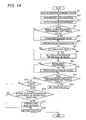
- FIG. 14 is a flow chart illustrating an operation during touch detection according to a third embodiment of this disclosure.
- FIG. 1 is a schematic configuration diagram illustrating a touch panel device 10 according to a first embodiment of this disclosure.
- a reference symbol “ 1 ” represents a touch sensor panel which includes a plurality of sensors.
- a reference symbol “ 11 ” shown by a broken wire in FIG. 1 represents a coordinate detection circuit.
- the coordinate detection circuit 11 includes a sensing unit 2 , a first baseline storing-and-updating unit (first baseline value management unit) 3 , a first touch detection unit 4 , a second baseline storing-and-updating unit (second baseline value management unit) 5 , and a second touch detection unit 6 .
- the sensing unit 2 uses the sensors of the touch sensor panel 1 to perform capacitance measurement, thereby acquiring measurement values.
- the first baseline storing-and-updating unit 3 generates first baseline values as touch detection references, and stores and updates the first baseline values.
- the first touch detection unit 4 performs touch detection based on the measurement values output from the sensing unit 2 and the first baseline values stored in the first baseline storing-and-updating unit 3 .
- the second baseline storing-and-updating unit 5 generates second baseline values and also stores and updates the second baseline values, based on the measurement values output from the sensing unit 2 , according to a rule different from that of the first baseline storing-and-updating unit 3 .
- the second touch detection unit 6 performs touch detection based on the measurement values output from the sensing unit 2 and the second baseline values stored in the second baseline storing-and-updating unit 5 .
- a reference symbol “ 7 ” represents a control unit controls the first baseline storing-and-updating unit 3 or the second baseline storing-and-updating unit 5 to update the baseline values stored therein, and the control unit computes touch coordinate data (an X coordinate and a Y coordinate) based on the touch detection result of the first touch detection unit 4 or the second touch detection unit 6 a and then outputs the touch coordinate data to a host computer (not shown).
- the touch sensor panel 1 includes a touch sensor substrate 33 and a cable 12 for exchanging signals between the coordinate detection circuit 11 and the touch sensor substrate 33 .
- the touch sensor substrate 33 includes a plurality of detection column wires (hereinafter, referred to as X sensors) 8 which extends in a column direction (corresponding to a y direction of FIG. 2 ) and is arranged in parallel with a predetermined pitch in a row direction (corresponding to an x direction of FIG. 2 ), and a plurality of detection row wires (hereinafter, referred to as Y sensors) 9 which extends in the row direction x and is arranged in parallel with a predetermined pitch in the column direction y.
- the X sensors 8 form one set of detection column wire groups X 0 to X 5 (hereinafter, referred to as an X sensor group) each of which is composed of a predetermined number of X sensors.
- the X sensors 8 including predetermined wires are electrically connected to a common connection wire (not shown) at an upper end and a lower end.
- the Y sensors 9 form one set of detection row wire groups Y 0 to Y 4 (hereinafter, referred to as a Y sensor group) each of which is composed of a predetermined number of Y sensors.
- the Y sensors 9 including predetermined wires are electrically connected to a common connection wire (not shown) at a left and a right end.
- the number of X sensor group is 6 (the X sensor group X 0 to X 5 of FIG. 2 ), and the number of Y sensor group is 5 (the Y sensor group Y 0 to Y 4 of FIG. 2 ) will be described.
- the X sensor group X 0 to X 5 are connected to terminals (not shown) formed on an upper end portion of the touch sensor substrate 33 , by leading wires from the common connection wires positioned on the upper end, respectively.
- the Y sensor group Y 0 to Y 4 are connected to terminals (not shown) formed on a upper end portion of the touch sensor substrate 33 positioned, by leading wires from the common connection wires positioned on the left end, respectively.
- an instructing body such as a finger of an operator, or a stylus
- touch capacitance is generated between the instructing body and the X and Y sensors.
- the number of the wires and the pitch of the wires of the X sensor group and the Y sensor group, and also the number, width, and pitch of detection wires which configures each X sensor group, and the number, width, and pitch of detection wires which constitute each Y sensor group can be appropriately selected based on resolution required for a touch coordinate (x touch coordinate data and y touch coordinate data) of the touch sensor panel 1 .
- each of the X and Y sensor group is not composed of a plurality of detection wires but is formed as one so-called solid wire, it is possible to secure high touch capacitance.
- the touch sensor substrate 33 is disposed on the front surface of an image display device or the like, the X and Y sensor group inhibit transmission of display light of the image display device or the like, and thus the transmittance of the display light decreases.
- each of the X and Y sensor group is composed of a plurality of detection wires, and the area of a slit-like opening between neighboring detection wires is set to be large, whereby a decrease in the transmittance of display light is suppressed.
- each of the X and Y sensor group is formed as one solid wire, and this configuration may be applied.
- each of the X sensor groups X 0 to X 5 and the Y sensor groups Y 0 to Y 4 serves one sensor, and measurement is performed in respective units of a sensor, not in s unit of a sensor group.
- the top surface layer of the touch sensor substrate 33 is a transparent substrate 34 , which is formed by a transparent glass material or a transparent resin.
- the X sensors 8 are formed by a transparent wire material such as ITO.
- a transparent inter-layer insulating film (not shown) is formed by silicon nitride (SiN) or the like so as to cover the X sensors 8 .
- the Y sensors 9 are formed by a transparent wire material.
- a transparent protective film (not shown) is formed by SiN or the like.
- the formation positions of the X sensors 8 and the Y sensors 9 may be reversed. That is, on the rear surface of the transparent substrate, the Y sensors 9 may be formed, and on the rear surface of the inter-layer insulating film, the X sensors 8 may be formed.
- the detection wires may not be transparent wires using a transparent wire material such as ITO, and may be formed by a metal such as aluminum. In this case, as described above, if each detection wire group is composed of a plurality of detection wires, and the area of a slit-like opening between neighboring detection wires is set to be large, the transmittance relative to display light is secured.
- the cable 12 of FIG. 2 is are mounted by flexible printed circuit (FPC) terminals with using of an anisotropic conductive film (ACF) so as to be connected to the terminals (not shown) of the touch sensor substrate 33 described above.
- the end portions of the detection wire groups formed on the touch sensor substrate 33 are electrically connected to the coordinate detection circuit 11 via the FPC.
- the touch sensor substrate 33 of FIG. 2 functions as a touch sensor panel.
- the sensing unit 2 is configured by an X switch circuit connected to the X sensors 8 , a Y switch circuit connected to the Y sensors 9 , an oscillation circuit, and a detection control circuit (which are not shown), and the sensing unit 2 sequentially scans the sensor groups of the X sensors 8 or the Y sensors 9 . That is, based on instructions of the detection control circuit, the sensing unit 2 sequentially applies an alternative signal from the oscillation circuit to the X or Y sensor group and performs capacitance measurement.
- the sensing unit 2 subtracts the first baseline values (capacitance measurement values in a state where the instructing body was far from the touch sensor panel 1 so as not to affect the touch sensor panel 1 ) stored in advance in the first baseline storing-and-updating unit 3 , from the measurement values, thereby obtaining difference values for touch determination, and outputs the difference values to the control unit 7 .
- Each difference value represents a change in electrostatic capacitance between the instructing body and an X or Y sensor group. Therefore, if the instructing body is far from the touch sensor panel 1 , the difference value becomes 0. Meanwhile, if the instructing body is in contact with or close to the touch sensor panel 1 (they are known collectively as “touch”), the difference value becomes large.
- the first touch detection unit 4 determines whether there is a touch. If there is any X sensor difference value exceeding a predetermined touch threshold value for the X sensors and there is any Y sensor difference value exceeding a predetermined touch threshold value for the Y sensors, the first touch detection unit 4 determines that there is a touch. As described above, the first touch detection unit 4 determines that the instructing body has touched an respective sensor group corresponding to the largest one of difference values of respective sensor group exceeding the predetermined touch threshold value, and outputs the detection result representing that there is a touch and the difference values of the X and Y sensor group to the control unit 7 .
- the control unit 7 Based on the touch detection result and the difference values corresponding to the X sensor group and the Y sensor group, the control unit 7 computes touch coordinate data (an X coordinate and a Y coordinate).
- touch coordinate data an X coordinate and a Y coordinate.
- the control unit 7 computes touch coordinate data based on the touch detection result and the difference values corresponding to the X and Y sensor group, for example, by a known complementing method disclosed in Japanese Patent Application Laid-Open No. 2008-134836, and outputs the touch coordinate data to the host computer (not shown).
- the second baseline storing-and-updating unit 5 and the second touch detection unit 6 shown in FIG. 1 are provided.
- the second touch detection unit 6 subtracts the second baseline values stored in the second baseline storing-and-updating unit 5 , from the measurement values, thereby obtaining difference values for touch determination, and outputs the difference values to the control unit 7 . If there is any X sensor difference value exceeding the predetermined touch threshold value for the X sensors and there is any Y sensor difference value exceeding a predetermined touch threshold value for the Y sensors, the second touch detection unit 6 determines that there is a touch.
- the second touch detection unit 6 determines that the instructing body has an X sensor group corresponding to the largest one of difference values of X sensor group exceeding the predetermined touch threshold value and a Y sensor group corresponding to the largest one of difference values of Y sensor group exceeding the predetermined touch threshold value, and outputs the detection result representing that there is a touch, and the difference values of the X and Y sensor group, to the control unit 7 .
- FIGS. 3 and 4 are flow charts illustrating operations of the touch panel device 10 .
- FIG. 5 is a graph illustrating examples of measurement values when the instructing body is not touched.
- FIG. 6 is a graph illustrating examples of normal baseline values having no deviation.
- FIG. 7 is a graph illustrating examples of difference values (values which are obtained by subtracting baseline values from measurement values) when the instructing body is not touched and the baseline values are normal.
- FIG. 8 is a graph illustrating examples of baseline values having deviations.
- FIG. 9 is a graph illustrating examples of difference values when the instructing body is not touched and baseline values have deviations.
- FIG. 10 is a graph illustrating examples of measurement values when the instructing body is touched a position (X 2 , Y 2 ).
- FIG. 11 is a graph illustrating difference values which are obtained from the measurement values of FIG. 10 and the baseline values shown in FIG. 6 and having no deviation.
- FIG. 12 is a graph illustrating difference values which are obtained from the measurement values of FIG. 10 and the baseline values shown in FIG. 8 and having deviations.
- initialization is performed immediately after the touch panel device 10 starts up, for example.
- the touch panel device 10 generates the first and second baseline values.
- the touch panel device 10 acquires sensor measurement values n number of times (wherein n is a predetermined integer of 1 or greater), and sets the averages of the measurement values as baseline values.
- the flow chart of that operation is FIG. 3 .
- Step S 1 the control unit 7 initializes a counter I, for counting the number of times of acquisition, to 0.
- Step S 2 the sensing unit 2 acquires sensor measurement values.
- the sensing unit 2 performs capacitance measurement on every sensor, thereby acquiring a predetermined number of measurement values.
- This predetermined number depends on the measuring method, and may be equal to the number of sensors, or may be less than the number of sensors by 2, or may be the product of the number of X sensor group and the number of Y sensor group. In the present embodiment, the same number of measurement values as the number of sensors is obtained (one measurement value is obtained with respect to every sensor).
- Step S 3 the first baseline storing-and-updating unit 3 and the second baseline storing-and-updating unit 5 stores the measurement values.
- the control unit 7 increments the counter i in Step S 4 and checks whether the value of the counter i is equal to n in Step S 5 . If the value of the counter i is not equal to n, the control unit 7 returns to Step S 2 . Meanwhile, if the value of the counter i is equal to n, the control unit 7 proceeds to Step S 6 in which the control unit 7 averages the n number of measurement values of each sensor.
- the first baseline storing-and-updating unit 3 and the second baseline storing-and-updating unit 5 divides the sum of the measurement values stored with respect to each sensor by n, thereby acquiring the average value of each sensor. Thereafter, in Step S 7 , the first baseline storing-and-updating unit 3 and the second baseline storing-and-updating unit 5 stores the average values as baseline values.
- FIG. 4 is a flow chart of one touch detecting process, and an operation of detecting a touch of the instructing body is performed by repeating the Steps of FIG. 4 at predetermined intervals.
- Step SA 1 the sensing unit 2 acquires sensor measurement values, similarly in Step S 2 during the baseline value generation.
- Step SA 2 the first touch detection unit 4 detects whether the instructing body is touched. In this touch detection, the first touch detection unit 4 subtracts the first baseline values stored in the first baseline storing-and-updating unit 3 from the measurement values acquired in Step SA 1 , thereby obtaining difference values. If there is any X sensor group 8 having a difference value exceeding the predetermined touch threshold value and there is a Y sensor group 9 having a difference value exceeding the predetermined touch threshold value, the first touch detection unit 4 determines that there is a touch, and the control unit computes a touch coordinate based on the difference values.
- Step SA 3 the control unit 7 outputs the touch coordinate to the host computer (not shown). Meanwhile, if the control unit 7 does not obtain any touch coordinate, in Step SA 3 , the control unit 7 outputs information representing that there is no touch, to the host computer (not shown).
- Step SA 4 it is determined in Step SA 4 that the result of the first touch detection of Step SA 2 represents that any instructing body is not touched, in Step SA 5 , the first baseline storing-and-updating unit 3 updates the first baseline values stored therein, according to the following Expression 1.
- Step SA 4 if it is determined in Step SA 4 that the result of the first touch detection of Step SA 2 represents that an instructing body is touched, the first baseline storing-and-updating unit 3 maintains the first baseline values without performing updating.
- [UPDATE BASELINE VALUE] W 1 ⁇ [BASELINE VALUE BEFORE UPDATE]+ W 2 ⁇ [SENSOR MEASUREMENT VALUE] (Expression 1)
- W1 and W2 represent predetermined weight values, and the sum of W1 and W2 is set to 1.0.
- measurement values of FIG. 5 is a value in case where any instructing body is not touched.
- the baseline values stored in the first baseline storing-and-updating unit 3 are values of FIG. 6 having small deviations
- difference values calculated in Step SA 2 is a value as shown in FIG. 7 .
- the touch threshold values are set to 20 (shown by alternate long and short dash lines in FIG. 7 )
- the first baseline values are corrected by updating of Step SA 5 .
- difference values are values as shown in FIG. 9 .
- Any difference value of X sensor group 8 and Y sensor group 9 exceeds the touch threshold values of 20 (shown by alternate long and short dash lines in FIG. 9 ). As a result, it is erroneously determined that there is a touch, and updating of the first baseline values is not performed.
- difference values of FIG. 11 are obtained from the baseline values of FIG. 6 having small deviations, and thus correct touch detection is possible.
- difference values of FIG. 12 are obtained from the baseline values of FIG. 8 , and an error is made in touch detection. As described above, if the baseline values have large deviations, it is impossible to correctly perform touch detection, and it is impossible to correct the deviations (in FIGS. 11 and 12 , the touch threshold values of 20 are shown by alternate long and short dash lines).
- Step SA 6 the second touch detection unit 6 performs touch detection.
- the second touch detection unit 6 subtracts the second baseline values stored in the second baseline storing-and-updating unit 5 from the measurement values acquired in Step SA 1 , thereby obtaining difference values. If there is any X sensor group 8 having a difference value exceeding the predetermined touch threshold value and there is a Y sensor group 9 having a difference value exceeding the predetermined touch threshold value, the second touch detection unit 6 determines that there is a touch of an instructing body.
- Step SA 7 the second baseline storing-and-updating unit 5 updates the second baseline values stored therein.
- the second baseline storing-and-updating unit 5 updates the baseline values according to the following Expression 2.
- Step SA 5 for updating the first baseline values if the baseline values have large deviations, touch detection may be impossible, and all of the baseline values may not be updated.
- Step SA 7 for updating the second baseline values since updating is always performed, it is guaranteed that, after any instructing body does not actually touch for a predetermined period, the baseline values become normal. If the first baseline values are normal, the touch detection of Step SA 6 is also always correctly performed.
- W4 of Expression 2 is set to a value smaller than W2 of Expression 1, whereby the degree of update is reduced.
- W2 is set to 0.25 (W1 is set to 0.75), and W4 is set to 0.05 (W3 is set to 0.95).
- [UPDATE BASELINE VALUE] W 3 ⁇ [BASELINE VALUE BEFORE UPDATE]+ W 4 ⁇ [SENSOR MEASUREMENT VALUE] (Expression 2)
- W3 and W4 represent predetermined weight values, and the sum of W3 and W4 is set to 1.0.
- Step SA 8 the control unit 7 determines whether the touch detection result of Step SA 6 represents that an instructing body is touched. If it is determined that there is a touch, in Step SA 9 , the control unit 7 sets a touch flag to 1. Meanwhile, if it is determined that there is no touch, the control unit 7 proceeds to Step SA 10 in which the control unit 7 checks the touch flag. If the touch flag 1 , in Step SA 11 , the first baseline storing-and-updating unit 3 regenerates first baseline values to be stored therein. In the present embodiment, like during initialization, the process shown in FIG. 3 is performed, whereby the first baseline values are generated. Next, in Step SA 12 , the control unit 7 sets the touch flag to 0. Due to the touch flag, after the second touch detection unit 6 detects that any instructing body is touched, at a timing when it is determined for the first time that there is no touch, the baseline value generation is performed.
- the operator regardless of any deviations of the baseline values, if the operator only touches the touch panel device with an instructing body such as a finger, it is possible to correct (generate) the baseline values for touch detection.
- the generation method of the baseline value in the initialization is a calculation of averages of measurement values acquired n number of times.
- the baseline values may be obtained by any other calculation method, or measurement values acquired in one time may be used as a baseline value.
- the first baseline storing-and-updating unit 3 and the second baseline storing-and-updating unit 5 use the same procedure to generate the baseline values.
- another method may be used.
- the first baseline value regeneration of Step SA 11 is the same as the first baseline value generation during initialization. However, another process different from the first baseline value generation during initialization may be used. Also, as described above, the timing when the first baseline value generation of Step SA 11 is performed is a timing when it is determined that there is no touch for the first time after the second touch detection unit 6 detects a touch. However, the timing when the first baseline value generation of Step SA 11 is performed may be any other timing such as a timing delayed for a predetermined time when there is no touch from when the second touch detection unit 6 detects a touch.
- FIG. 13 is a flow chart illustrating an operation of a touch panel device 10 of the second embodiment.
- the second baseline storing-and-updating unit 5 and the second touch detection unit 6 operate only when updating of the first baseline storing-and-updating unit 3 is in a stop state will be described.
- Step SB 1 the sensing unit 2 acquires sensor measurement values.
- Step SB 2 the first touch detection unit 4 performs touch detection.
- Step SB 3 the control unit 7 outputs touch information to the host computer. If it is determined in Step SB 2 that any instructing body is not touched, in Step SB 5 , updating of the first baseline values is performed according to the above Expression 1. Meanwhile, if it determined in Step SB 2 that there is a touch, in Step SB 4 , it is determined to maintain the first baseline values without performing updating.
- Step SB 6 the control unit 7 determines whether updating of the first baseline values has been performed in Step SB 5 . If updating has been performed, the control unit 7 sets the current time as t 1 , in Step SB 7 , and sets an initial flag to 1 in Step SB 8 , and then finishes the process. If updating has not been performed, in Step SB 9 , the control unit 7 determines whether a different between t 1 and the current time is a predetermined threshold value Th 1 or more. If the difference between t 1 and the current time is less than the predetermined threshold value Th 1 , the control unit 7 finishes the process.
- Th 1 a predetermined threshold value
- Step SB 10 it is checked whether the predetermined threshold value Th 1 or more has elapsed from the latest performance time of updating of Step SB 5 .
- Step SB 10 the control unit 7 checks whether the initial flag is 1. If the initial flag is 1, in Step SB 11 , the second baseline storing-and-updating unit 5 generates the second baseline values. In a case where Step SB 10 and the subsequent steps have not been performed but are performed for the first time (a case where the second baseline storing-and-updating unit 5 and the second touch detection unit 6 stopped and then restart), the initial flag becomes 1. Therefore, in this case, it is necessary to regenerate the second baseline values (initialize the second baseline values) and activate the operations of the second touch detection unit 6 and the second baseline storing-and-updating unit 5 . As a method of regenerating the second baseline values, for example, the first baseline values stored in the first baseline storing-and-updating unit 3 can be copied into the second baseline storing-and-updating unit 5 , whereby second baseline value generation is performed.
- Step SB 12 the control unit 7 clears the initial flag to 0.
- Steps SB 13 to SB 19 are performed in the same procedure as that of Steps SA 6 to SA 12 of the above described first embodiment.
- the second touch detection unit 6 performs touch detection.
- Step SB 14 the second baseline storing-and-updating unit 5 updates the second baseline values stored therein.
- Step SB 15 the control unit 7 checks whether the result of the touch detection of Step SB 13 represents that there is a touch. If it is determined that there is a touch, in Step SB 16 , the control unit 7 sets the touch flag to 1. Meanwhile, if it is determined that there is no touch, the control unit 7 proceeds to Step SB 17 .
- Step SB 17 the control unit 7 checks the touch flag. If the touch flag is 1, in Step SB 18 , the first baseline storing-and-updating unit 3 regenerates first baseline values to be stored therein. Next, in Step SB 19 , the control unit 7 sets the touch flag to 0.
- the operations of the second baseline storing-and-updating unit 5 and the second touch detection unit 6 are stopped, whereby it is possible to suppress an increase in the process time.
- the first baseline values stored in the first baseline storing-and-updating unit 3 are copied into the second baseline storing-and-updating unit 5 , whereby second baseline value regeneration is performed.
- second baseline value regeneration any other method is used for second baseline value regeneration.
- FIG. 13 is a flow chart illustrating an operation of a touch panel device 10 of the third embodiment.
- Step SC 1 the sensing unit 2 acquires sensor measurement values.
- Step SC 2 the first touch detection unit 4 performs touch detection.
- Step SC 3 the control unit 7 outputs touch information to the host computer. If it is determined in Step SC 2 that any instructing body is not touched, in Step SC 5 , updating of the first baseline values is performed according to the above-described Expression 1. Meanwhile, if it determined in Step SC 2 that there is a touch, in Step SC 4 , it is determined to maintain the first baseline values without performing updating.
- Step SC 6 the second touch detection unit performs touch detection.
- Step SC 8 an update stop period of the second baseline values is set based on the touch detection result of Step SC 6 . For example, if it is determined in Step SC 7 that it is a touch start time, in Step SC 8 , based on the number of X sensor group exceeding the touch threshold value and the number of Y sensor group exceeding the touch threshold value, seconds for the update stop period is determined. If both of the number of X sensor group and the number of Y sensor group are 1, the update stop period is set to 30 seconds.
- the update stop period is set to 15 seconds, and if the other is 3 or more, the update stop period is set to 0 second (an update stop period is not set).
- Step SC 9 the second baseline storing-and-updating unit 5 performs updating of the second baseline values stored therein.
- Step SC 10 of the present embodiment Expression 2 which is used in Step SA 7 of the first embodiment is applied, but the values of W3 and W4 are changed.
- the second baseline values are always updated.
- W3 and W4 are set to the same values as those of W1 and W2 of Expression 1, or W4 is set to be larger than W2 (W3 is set to be smaller than W1), it is possible to change the second baseline values to normal states as quickly as possible. For example, W1 and W2 are set to 0.75 and 0.25, respectively, whereas W3 and W4 are set to 0.65 and 0.35, respectively.
- Steps SC 11 to SC 13 are the same processes as Steps SA 8 to SA 10 of the first embodiment.
- the control unit 7 checks whether the touch detection result of Step SC 6 represents that there is a touch. If it is determined that there is a touch, in Step SC 12 , the control unit 7 sets the touch flag to 1. If it is determined that there is no touch, the control unit 7 proceeds to Step SC 13 in which the control unit 7 checks the touch flag. If the touch flag is 1, in Step SC 14 , the control unit 7 checks whether the result of the first touch detection of Step SC 2 is equivalent to the result of the second touch detection of Step SC 6 (for example, whether differences in touch coordinates are within a predetermined range).
- Step SC 15 If the result of the first touch detection of Step SC 2 is not equivalent to the result of the second touch detection of Step SC 6 , in Step SC 15 , regeneration of first baseline values to be stored in the first baseline storing-and-updating unit 3 is performed. Next, the control unit 7 sets the touch flag to 0 in Step SC 16 , and finishes the process.
- Step SC 14 Since the result of the second touch detection is correct, in a case where it is determined in Step SC 14 that the two touch detection results are equivalent, it can be said that the result of the first touch detection is correct, that is, a possibility that the baseline values of the first baseline storing-and-updating unit 3 have no deviation is high.
- the control unit 7 skips Step S 15 for generation of the first baseline values to be stored in the first baseline storing-and-updating unit 3 , and proceeds to Step SC 16 in which the control unit 7 sets the touch flag to 0. If first baseline value generation is performed even though the baseline values have no deviation, too much process time is required, and there is a risk that deviations may increase. However, if the determination of Step SC 14 is added, it is possible to avoid those problems.
- the update stop period is set according to three criteria based on the number of X sensor group exceeding the touch threshold value and the number of Y sensor group exceeding the touch threshold value.
- the update stop period may be set according to any other criteria.
- whether the result of the first touch detection is equivalent to the result of the second touch detection is determined by determining whether differences in touch coordinates are within the predetermined range.
- any other determination criterion may be used.
Landscapes
- Engineering & Computer Science (AREA)
- General Engineering & Computer Science (AREA)
- Theoretical Computer Science (AREA)
- Human Computer Interaction (AREA)
- Physics & Mathematics (AREA)
- General Physics & Mathematics (AREA)
- Position Input By Displaying (AREA)
Applications Claiming Priority (2)
| Application Number | Priority Date | Filing Date | Title |
|---|---|---|---|
| JP2014-056391 | 2014-03-19 | ||
| JP2014056391A JP6314570B2 (ja) | 2014-03-19 | 2014-03-19 | タッチパネル装置 |
Publications (2)
| Publication Number | Publication Date |
|---|---|
| US20150268764A1 US20150268764A1 (en) | 2015-09-24 |
| US9507475B2 true US9507475B2 (en) | 2016-11-29 |
Family
ID=54142088
Family Applications (1)
| Application Number | Title | Priority Date | Filing Date |
|---|---|---|---|
| US14/643,184 Active US9507475B2 (en) | 2014-03-19 | 2015-03-10 | Touch panel device with second touch detector |
Country Status (2)
| Country | Link |
|---|---|
| US (1) | US9507475B2 (enExample) |
| JP (1) | JP6314570B2 (enExample) |
Families Citing this family (10)
| Publication number | Priority date | Publication date | Assignee | Title |
|---|---|---|---|---|
| US9594456B2 (en) * | 2014-12-19 | 2017-03-14 | Apex Material Technology Corp. | Background signal processing system and background signal processing method |
| US9569033B2 (en) * | 2014-12-19 | 2017-02-14 | Apex Material Technology Corp. | Background signal processing system and background signal processing method |
| JP6416691B2 (ja) * | 2015-05-14 | 2018-10-31 | アルプス電気株式会社 | 入力装置及び入力装置の動作方法 |
| KR20160137259A (ko) * | 2015-05-22 | 2016-11-30 | 삼성전자주식회사 | 터치 패널을 포함하는 전자 장치 및 그 제어 방법 |
| US10466839B2 (en) * | 2016-03-30 | 2019-11-05 | Synaptics Incorporated | Dynamic differential algorithm for side touch signals |
| US10795518B2 (en) * | 2018-10-30 | 2020-10-06 | Synaptics Incorporated | Baseline update for input object detection |
| JP7200056B2 (ja) * | 2019-06-28 | 2023-01-06 | 株式会社東海理化電機製作所 | タッチセンサ、制御装置、およびコンピュータプログラム |
| JP7196026B2 (ja) * | 2019-06-28 | 2022-12-26 | 株式会社東海理化電機製作所 | タッチセンサ、制御装置、およびコンピュータプログラム |
| CN110971225A (zh) * | 2019-12-17 | 2020-04-07 | 珠海格力电器股份有限公司 | 触摸按键抗干扰方法及电路 |
| TWI779547B (zh) * | 2020-04-05 | 2022-10-01 | 昇佳電子股份有限公司 | 電容感測裝置操作方法 |
Citations (5)
| Publication number | Priority date | Publication date | Assignee | Title |
|---|---|---|---|---|
| JP2007208682A (ja) | 2006-02-02 | 2007-08-16 | Matsushita Electric Ind Co Ltd | タッチパネル |
| JP2008134836A (ja) | 2006-11-28 | 2008-06-12 | Wacom Co Ltd | タッチパネル装置 |
| JP2012150747A (ja) | 2011-01-21 | 2012-08-09 | Mitsubishi Electric Corp | タッチパネル装置 |
| US20120283972A1 (en) * | 2011-05-05 | 2012-11-08 | Synaptics Incorporated | System and method for determining user input using dual baseline modes |
| US8773146B1 (en) * | 2010-04-16 | 2014-07-08 | Cypress Semiconductor Corporation | Waterproof scanning of a capacitive sense array |
Family Cites Families (5)
| Publication number | Priority date | Publication date | Assignee | Title |
|---|---|---|---|---|
| JP4714070B2 (ja) * | 2006-04-14 | 2011-06-29 | アルプス電気株式会社 | 入力装置 |
| JP4881331B2 (ja) * | 2008-01-29 | 2012-02-22 | 株式会社東海理化電機製作所 | タッチスイッチ |
| JP5220886B2 (ja) * | 2011-05-13 | 2013-06-26 | シャープ株式会社 | タッチパネル装置、表示装置、タッチパネル装置のキャリブレーション方法、プログラムおよび記録媒体 |
| JP5978663B2 (ja) * | 2012-03-12 | 2016-08-24 | 株式会社デンソー | 表示装置 |
| CN103677452B (zh) * | 2012-08-30 | 2017-05-24 | 华为终端有限公司 | 一种电容式触摸屏的校准方法和电容式触摸装置 |
-
2014
- 2014-03-19 JP JP2014056391A patent/JP6314570B2/ja active Active
-
2015
- 2015-03-10 US US14/643,184 patent/US9507475B2/en active Active
Patent Citations (5)
| Publication number | Priority date | Publication date | Assignee | Title |
|---|---|---|---|---|
| JP2007208682A (ja) | 2006-02-02 | 2007-08-16 | Matsushita Electric Ind Co Ltd | タッチパネル |
| JP2008134836A (ja) | 2006-11-28 | 2008-06-12 | Wacom Co Ltd | タッチパネル装置 |
| US8773146B1 (en) * | 2010-04-16 | 2014-07-08 | Cypress Semiconductor Corporation | Waterproof scanning of a capacitive sense array |
| JP2012150747A (ja) | 2011-01-21 | 2012-08-09 | Mitsubishi Electric Corp | タッチパネル装置 |
| US20120283972A1 (en) * | 2011-05-05 | 2012-11-08 | Synaptics Incorporated | System and method for determining user input using dual baseline modes |
Also Published As
| Publication number | Publication date |
|---|---|
| JP6314570B2 (ja) | 2018-04-25 |
| JP2015179393A (ja) | 2015-10-08 |
| US20150268764A1 (en) | 2015-09-24 |
Similar Documents
| Publication | Publication Date | Title |
|---|---|---|
| US9507475B2 (en) | Touch panel device with second touch detector | |
| EP3654155B1 (en) | Electronic device equipped with touch panel and update method of base line value | |
| CN109478113B (zh) | 用于检测和确认触摸输入的方法 | |
| US9207801B2 (en) | Force sensing input device and method for determining force information | |
| US10061433B2 (en) | Touch-type input device | |
| US20120319987A1 (en) | System and method for calibrating an input device | |
| JP5055231B2 (ja) | タッチパネルのタッチ位置検出方法 | |
| US10139964B2 (en) | Control apparatus for a touch panel and control method for the touch panel | |
| US20100271322A1 (en) | Position detecting method for touchscreen panel, touchscreen panel, and electronic apparatus | |
| US9459729B2 (en) | Sensing baseline management | |
| WO2008057237A2 (en) | Method and system for calibrating a touch screen | |
| CN108475137B (zh) | 使用混合估计方法减轻共模显示噪声 | |
| US20150355740A1 (en) | Touch panel system | |
| US10488987B2 (en) | Touch panel apparatus | |
| WO2011101894A1 (ja) | タッチパネル装置 | |
| US10379672B2 (en) | Dynamic proximity object detection | |
| JP5814704B2 (ja) | タッチパネルコントローラ、タッチパネルの制御方法、それを用いた入力装置および電子機器 | |
| KR100480155B1 (ko) | 다중 터치패널의 구동방법, 구동장치 및 그를 사용한 다중터치패널 장치 | |
| US10108298B2 (en) | Portable electronic device and touch control chip and touch control method thereof | |
| KR20160091642A (ko) | 자동 모드 전환 방법 | |
| CN112513796B (zh) | 触控面板检测方法与触控面板 | |
| US12141400B2 (en) | Input detection device, input detection method, and recording medium recording an input detection program for accurately detecting an input position of an input operation on a display panel | |
| US9317167B2 (en) | Touch control system and signal processing method thereof | |
| US20140327648A1 (en) | Input Device, Control Unit and Method for Ascertaining a Position | |
| JP2024175886A (ja) | 入力検出装置、入力検出方法、及び入力検出プログラム |
Legal Events
| Date | Code | Title | Description |
|---|---|---|---|
| AS | Assignment |
Owner name: MITSUBISHI ELECTRIC CORPORATION, JAPAN Free format text: ASSIGNMENT OF ASSIGNORS INTEREST;ASSIGNORS:MIYAHARA, KAGEYASU;MORI, SEIICHIRO;REEL/FRAME:035126/0360 Effective date: 20150203 |
|
| STCF | Information on status: patent grant |
Free format text: PATENTED CASE |
|
| MAFP | Maintenance fee payment |
Free format text: PAYMENT OF MAINTENANCE FEE, 4TH YEAR, LARGE ENTITY (ORIGINAL EVENT CODE: M1551); ENTITY STATUS OF PATENT OWNER: LARGE ENTITY Year of fee payment: 4 |
|
| AS | Assignment |
Owner name: TRIVALE TECHNOLOGIES, LLC, CALIFORNIA Free format text: ASSIGNMENT OF ASSIGNORS INTEREST;ASSIGNOR:MITSUBISHI ELECTRIC CORPORATION;REEL/FRAME:059024/0437 Effective date: 20211228 |
|
| MAFP | Maintenance fee payment |
Free format text: PAYMENT OF MAINTENANCE FEE, 8TH YEAR, LARGE ENTITY (ORIGINAL EVENT CODE: M1552); ENTITY STATUS OF PATENT OWNER: LARGE ENTITY Year of fee payment: 8 |