US9506844B2 - Measuring device for measuring dust in flue gas - Google Patents
Measuring device for measuring dust in flue gas Download PDFInfo
- Publication number
- US9506844B2 US9506844B2 US14/388,591 US201314388591A US9506844B2 US 9506844 B2 US9506844 B2 US 9506844B2 US 201314388591 A US201314388591 A US 201314388591A US 9506844 B2 US9506844 B2 US 9506844B2
- Authority
- US
- United States
- Prior art keywords
- weighing
- measuring device
- measuring
- flue gas
- module
- Prior art date
- Legal status (The legal status is an assumption and is not a legal conclusion. Google has not performed a legal analysis and makes no representation as to the accuracy of the status listed.)
- Active, expires
Links
- UGFAIRIUMAVXCW-UHFFFAOYSA-N Carbon monoxide Chemical compound [O+]#[C-] UGFAIRIUMAVXCW-UHFFFAOYSA-N 0.000 title claims abstract description 27
- 239000003546 flue gas Substances 0.000 title claims abstract description 27
- 239000000428 dust Substances 0.000 title claims abstract description 13
- 238000005303 weighing Methods 0.000 claims abstract description 59
- 239000000523 sample Substances 0.000 claims abstract description 14
- 238000009434 installation Methods 0.000 claims abstract description 13
- 239000004449 solid propellant Substances 0.000 claims abstract description 7
- 239000007789 gas Substances 0.000 claims description 5
- 238000005259 measurement Methods 0.000 description 14
- 238000000034 method Methods 0.000 description 7
- 238000010438 heat treatment Methods 0.000 description 5
- 230000003287 optical effect Effects 0.000 description 3
- 239000013618 particulate matter Substances 0.000 description 3
- 238000004140 cleaning Methods 0.000 description 2
- 238000009833 condensation Methods 0.000 description 2
- 230000005494 condensation Effects 0.000 description 2
- 239000002245 particle Substances 0.000 description 2
- 238000001556 precipitation Methods 0.000 description 2
- 238000011144 upstream manufacturing Methods 0.000 description 2
- 239000002028 Biomass Substances 0.000 description 1
- 239000000809 air pollutant Substances 0.000 description 1
- 231100001243 air pollutant Toxicity 0.000 description 1
- XAGFODPZIPBFFR-UHFFFAOYSA-N aluminium Chemical compound [Al] XAGFODPZIPBFFR-UHFFFAOYSA-N 0.000 description 1
- 229910052782 aluminium Inorganic materials 0.000 description 1
- 238000002485 combustion reaction Methods 0.000 description 1
- 230000001143 conditioned effect Effects 0.000 description 1
- 238000010276 construction Methods 0.000 description 1
- 238000000151 deposition Methods 0.000 description 1
- 238000013461 design Methods 0.000 description 1
- 238000011161 development Methods 0.000 description 1
- 231100001261 hazardous Toxicity 0.000 description 1
- 238000009413 insulation Methods 0.000 description 1
- 238000012544 monitoring process Methods 0.000 description 1
- 230000010355 oscillation Effects 0.000 description 1
- 239000012716 precipitator Substances 0.000 description 1
- 238000002310 reflectometry Methods 0.000 description 1
- 238000003860 storage Methods 0.000 description 1
- 238000006467 substitution reaction Methods 0.000 description 1
- 239000002023 wood Substances 0.000 description 1
Images


Classifications
-
- G—PHYSICS
- G01—MEASURING; TESTING
- G01N—INVESTIGATING OR ANALYSING MATERIALS BY DETERMINING THEIR CHEMICAL OR PHYSICAL PROPERTIES
- G01N1/00—Sampling; Preparing specimens for investigation
- G01N1/02—Devices for withdrawing samples
- G01N1/22—Devices for withdrawing samples in the gaseous state
- G01N1/2247—Sampling from a flowing stream of gas
- G01N1/2258—Sampling from a flowing stream of gas in a stack or chimney
-
- G—PHYSICS
- G01—MEASURING; TESTING
- G01N—INVESTIGATING OR ANALYSING MATERIALS BY DETERMINING THEIR CHEMICAL OR PHYSICAL PROPERTIES
- G01N33/00—Investigating or analysing materials by specific methods not covered by groups G01N1/00 - G01N31/00
- G01N33/0004—Gaseous mixtures, e.g. polluted air
- G01N33/0009—General constructional details of gas analysers, e.g. portable test equipment
-
- G—PHYSICS
- G01—MEASURING; TESTING
- G01N—INVESTIGATING OR ANALYSING MATERIALS BY DETERMINING THEIR CHEMICAL OR PHYSICAL PROPERTIES
- G01N5/00—Analysing materials by weighing, e.g. weighing small particles separated from a gas or liquid
-
- G—PHYSICS
- G01—MEASURING; TESTING
- G01N—INVESTIGATING OR ANALYSING MATERIALS BY DETERMINING THEIR CHEMICAL OR PHYSICAL PROPERTIES
- G01N15/00—Investigating characteristics of particles; Investigating permeability, pore-volume or surface-area of porous materials
- G01N15/06—Investigating concentration of particle suspensions
- G01N15/0606—Investigating concentration of particle suspensions by collecting particles on a support
- G01N15/0618—Investigating concentration of particle suspensions by collecting particles on a support of the filter type
-
- G—PHYSICS
- G01—MEASURING; TESTING
- G01N—INVESTIGATING OR ANALYSING MATERIALS BY DETERMINING THEIR CHEMICAL OR PHYSICAL PROPERTIES
- G01N1/00—Sampling; Preparing specimens for investigation
- G01N1/02—Devices for withdrawing samples
- G01N1/22—Devices for withdrawing samples in the gaseous state
- G01N1/2247—Sampling from a flowing stream of gas
- G01N1/2258—Sampling from a flowing stream of gas in a stack or chimney
- G01N2001/2261—Sampling from a flowing stream of gas in a stack or chimney preventing condensation (heating lines)
-
- G—PHYSICS
- G01—MEASURING; TESTING
- G01N—INVESTIGATING OR ANALYSING MATERIALS BY DETERMINING THEIR CHEMICAL OR PHYSICAL PROPERTIES
- G01N1/00—Sampling; Preparing specimens for investigation
- G01N1/02—Devices for withdrawing samples
- G01N1/22—Devices for withdrawing samples in the gaseous state
- G01N2001/2285—Details of probe structures
-
- G—PHYSICS
- G01—MEASURING; TESTING
- G01N—INVESTIGATING OR ANALYSING MATERIALS BY DETERMINING THEIR CHEMICAL OR PHYSICAL PROPERTIES
- G01N15/00—Investigating characteristics of particles; Investigating permeability, pore-volume or surface-area of porous materials
- G01N2015/0096—Investigating consistence of powders, dustability, dustiness
-
- G—PHYSICS
- G01—MEASURING; TESTING
- G01N—INVESTIGATING OR ANALYSING MATERIALS BY DETERMINING THEIR CHEMICAL OR PHYSICAL PROPERTIES
- G01N2291/00—Indexing codes associated with group G01N29/00
- G01N2291/02—Indexing codes associated with the analysed material
- G01N2291/024—Mixtures
- G01N2291/02408—Solids in gases, e.g. particle suspensions
Definitions
- the invention is directed to a measuring device, particularly for measuring dust in the flue gas of small-scale furnace installations for solid fuels, having a measuring probe and a heated suction hose connecting the measuring probe to a weighing device with a filter device.
- 1st BImSchV stipulates regular monitoring of furnace installations and prescribes maximum levels for fine particulate matter in the flue gas depending on the type of furnace installations.
- limiting values of 0.02 g/m 3 are called for as of 2015. These limiting values present a challenge to metrology even though the basic principle is simple and remains the same, namely, to guide a predefined amount of the flue gas of a furnace installation through a filter and ascertain the difference of mass before and after the measuring process in order to determine the fine particulates content in the flue gas.
- optical systems such as those described, for example, in DE 10 2006 039670 A1, DE 10 2005 009582 A1 or DE 6 9627922 T2 are currently favored in technical development.
- a device mentioned in this reference has an elastic element in the form of a hollow pipe that narrows in diameter from a clamped-in first end toward a second, free end.
- the free end of the pipe is widened and carries a platform-like base for articles to be weighed.
- the mass of the article to be weighed can be deduced from the change in the resonant frequency of the vibratory pipe in a loaded condition and when loaded by the article to be weighed.
- An accurate weighing of a sample appears possible with this device, but this known device is fundamentally unsuited for analyzing flue gas in a solid fuel furnace.
- a predefined amount of the flue gas flews through a vibratory tube, whereupon a quantity of dust deposits on a filter device of the tube.
- the tube is set in oscillation and the dust quantity is calculated from the deviation from the predetermined resonant frequency and/or natural frequency of the tube by an evaluating device.
- a measuring device with a weighing device comparable to DE 2 553 638 C2 is known from U.S. Pat. No. 7,947,503 B2.
- a heated suction hose is provided between a gas inlet opening and the weighing device. By heating the suction hose, particles are prevented from depositing in the hose upstream of the weighing device and distorting the measurement results. Measuring accuracy is appreciably increased through this step.
- an object of the invention is to provide a practice-oriented measuring device in which, in particular, the fine particulates measurements according to 1st BImSchV can be carried out in a simple manner but very accurately.
- a measuring device particularly for measuring dust in the flue gas of small-scale furnace installations for solid fuels, having a measuring probe and a heated suction hose connecting the measuring probe to a weighing device with a filter device as set forth herein
- the above-stated set of technical problems is remedied through the features consisting in that the weighing device is arranged in a weighing module, and in that the weighing device is thermally insulated in the weighing module.
- the measuring device according to the invention has many advantages.
- the heated hose and the thermal insulation of the weighing device ensure that, after a heating-up phase, there is hardly any condensation or the like precipitation on the path from the probe to the location where the fine particulate matter is separated and weighed.
- precipitators of any kind upstream of the weighing location can be dispensed with, as can the admixture of fresh air.
- the weighing device is arranged in a heatable sleeve in the weighing module.
- the invention also provides for an exact measurement of a flue gas particularly of a small-scale furnace installation for solid fuels. These measurements are to be carried out at a flue gas temperature of about 70°.
- a flue gas temperature of about 70°.
- a hose temperature sensor arranged between the weighing device and hose is provided as an actual-temperature transducer.
- the hose temperature sensor is detachably connected to the weighing device and to one end of the suction hose to prevent the sensor from damage when the suction hose is bent and from falling out or the like on the one hand and to allow easy cleaning of the hose temperature sensor and flue gas hose on the other hand.
- the weighing device itself has a vibratory tube arranged in the sleeve, the free end of the vibratory tube being disposed on the gas outlet side and closed by a filter cartridge fitted thereto.
- the quantity of dust is determined in a manner comparable to the method known from DE 10 2007 041 369 A1, and the attached filter cartridge ensures a rapid exchange thereof, because an unused filter cartridge is required for every measurement.
- the weighing module is designed in a self-contained manner and can be removed from a case together with a display-and-control module on a telescoping stand.
- the measuring device including equipment, be accommodated completely within a case, for example, in an aluminum case of sufficient stability.
- This case can advisably be provided additionally with rollers or the like on the underside.
- the weighing module With the weighing device combined with the display-and-control module, is pulled out on a telescoping stand after opening the case until the display-and-control module is at a convenient working height for the operator.
- the suction hose connecting the weighing module with weighing device to the measuring probe is accordingly also pulled out of the case at the same time.
- the measuring probe is also easily accessible and can also be exchanged if need be.
- a holding device for the heated suction hose is provided inside the case.
- the weighing module with the display-and-control module is removably connected to the stand and, for example, depending on construction, is used on a further stand separate from the case.
- the weighing module is provided with a handle. Also provided at the handle is an operating layer, for example, for a clamping device or the like, for unlocking from a stand.
- a connection hose leads from the weighing module into the interior of the case to the pump arranged therein.
- a flue gas condenser is provided, in order to protect this pump and the sensors further arranged therein.
- a folding case cover is preferably provided with a flue gas condenser of this type. In an open position of the cover locked vertically upward, gravitational force can be incorporated in a condensation process.
- the flue gas condenser is preferably fastened to the case cover so as to be detachable for cleaning, exchanging filters or the like.
- a front flap further improves the accessibility of the interior of the case.
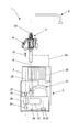
- FIG. 1 is a schematic front view of the measuring device overall
- FIG. 2 is an enlarged section through the weighing module with connected display-and-control module.
- FIG. 1 schematically shows a measuring device 1 , according to an embodiment of the invention, which can be accommodated in its entirety in a case 2 for transport or storage.
- the case 2 has a folding case cover 3 which, as is shown, can be locked in a vertical position.
- a front flap, not shown in FIG. 1 which extends approximately over half of the height of the case, improves accessibility to the interior of the case.
- a weighing module 5 with display-and-control module 6 connected to it can be pulled out of the interior of the case on a telescoping stand 4 to a convenient working height.
- a handle 7 is helpful for this purpose, and a lever 8 of a clamping device, for example, by which the weighing module 5 with display-and-control module 6 can be detachably locked to the stand 4 , is also arranged at the handle 7 .
- a heatable suction hose 10 leads from a measuring probe 9 to be introduced into a flue gas flow for measurement to the weighing module 5 and is detachably connected at the weighing module 5 .
- the suction hose can be removed from a hose temperature sensor 13 , and the electrical connection to the weighing module 5 can be separated after detaching a plug 14 (see FIG. 2 ) so that it is possible to clean the suction hose 10 in a simple manner separate from the measuring device 1 .
- the hose temperature sensor 13 is connected to a tube 15 of the weighing device 16 .
- the tube 15 is fixedly clamped in a cover 17 at one end and at the other, vibratory free end, is closed by an attached filter cartridge 18 .
- the tube 15 centrally penetrates an evacuable sleeve 19 so as to be closed at the top by cover 17 and on the bottom by a closure cover 20 with a suction hose connection piece 21 .
- Axial bore holes which serve to receive heating cartridges, which also make it possible to heat the weighing device 16 , are inserted into the wall of the sleeve 19 .
- An electric connection cable 22 leads from the display-and-control module 6 , in which the weighing electronics are also preferably arranged, into the interior of the case and is connected therein to control electronics 23 .
- connection hose 24 leads from the suction hose connection piece 21 of the weighing module 5 to a flue gas condenser 25 .
- the flue gas condenser 25 is detachably fastened to the vertically lockable case cover 3 .
- a further connection hose 26 shown schematically, is connected to the flue gas condenser 25 on the output side and is connected at the other end via a hose connection 27 with a filter, not shown, to a measuring device 28 , shown schematically, for measuring the normal volume flow.
- a pump 29 for example, a rotary vane pump controlled by the control electronics 23 , generates the differential pressure required for gas throughput, after which the gas that has been sucked out exits into the environment.
- the flue gas is supplied to further sensors, e.g., a sensor 31 for O 2 and/or a sensor 3 for CO, by a further pump 30 , for example, a diaphragm pump controlled by the control electronics 23 , and the measurements of the flue gas are evaluated by the control electronics 23 and can be displayed by the display-and-control module 6 .
- a further pump 30 for example, a diaphragm pump controlled by the control electronics 23 , and the measurements of the flue gas are evaluated by the control electronics 23 and can be displayed by the display-and-control module 6 .
- a cover plate 34 covers the sensor arrangement with sensors 31 , 32 , measuring device 28 , control electronics 23 , and pumps 29 , 30 .
Landscapes
- Chemical & Material Sciences (AREA)
- Health & Medical Sciences (AREA)
- Life Sciences & Earth Sciences (AREA)
- Analytical Chemistry (AREA)
- General Health & Medical Sciences (AREA)
- Pathology (AREA)
- Immunology (AREA)
- Physics & Mathematics (AREA)
- General Physics & Mathematics (AREA)
- Biochemistry (AREA)
- Engineering & Computer Science (AREA)
- Combustion & Propulsion (AREA)
- Medicinal Chemistry (AREA)
- Food Science & Technology (AREA)
- Biomedical Technology (AREA)
- Molecular Biology (AREA)
- Dispersion Chemistry (AREA)
- Sampling And Sample Adjustment (AREA)
- Measuring Oxygen Concentration In Cells (AREA)
Applications Claiming Priority (4)
| Application Number | Priority Date | Filing Date | Title |
|---|---|---|---|
| DE102012006052 | 2012-03-27 | ||
| DE102012006052A DE102012006052A1 (de) | 2012-03-27 | 2012-03-27 | Messvorrichtung |
| DE102012006052.1 | 2012-03-27 | ||
| PCT/DE2013/000163 WO2013143523A1 (de) | 2012-03-27 | 2013-03-25 | Messvorrichtung |
Publications (2)
| Publication Number | Publication Date |
|---|---|
| US20150059443A1 US20150059443A1 (en) | 2015-03-05 |
| US9506844B2 true US9506844B2 (en) | 2016-11-29 |
Family
ID=48443998
Family Applications (1)
| Application Number | Title | Priority Date | Filing Date |
|---|---|---|---|
| US14/388,591 Active 2033-09-13 US9506844B2 (en) | 2012-03-27 | 2013-03-25 | Measuring device for measuring dust in flue gas |
Country Status (6)
| Country | Link |
|---|---|
| US (1) | US9506844B2 (zh) |
| EP (1) | EP2831563B1 (zh) |
| CN (1) | CN104204763B (zh) |
| DE (2) | DE102012006052A1 (zh) |
| PL (1) | PL2831563T3 (zh) |
| WO (1) | WO2013143523A1 (zh) |
Families Citing this family (3)
| Publication number | Priority date | Publication date | Assignee | Title |
|---|---|---|---|---|
| CN107741375B (zh) * | 2017-10-20 | 2020-10-23 | 中煤科工集团重庆研究院有限公司 | 一种粉尘沉积检测感应单元、系统及方法 |
| CN108535155B (zh) * | 2018-03-01 | 2020-06-26 | 四川大学 | 直接封装空气称量测定大坝泄洪雾化浓度的方法 |
| DE102018003755A1 (de) * | 2018-05-09 | 2019-11-14 | Wöhler Technik GmbH | Messverfahren |
Citations (15)
| Publication number | Priority date | Publication date | Assignee | Title |
|---|---|---|---|---|
| US3926271A (en) | 1975-02-03 | 1975-12-16 | Rupprecht Georg | Microbalance |
| US4154088A (en) | 1975-02-12 | 1979-05-15 | F. L. Smidth & Co. | Apparatus for measuring the particulate matter content of a gas |
| US4442699A (en) * | 1980-02-25 | 1984-04-17 | Centre De Recherches Metallurgiques-Centrum Voor Research In De Metallurgie | Monitoring the dust content of gaseous fluid |
| US5694208A (en) | 1995-03-24 | 1997-12-02 | Nohmi Bosai Ltd. | Sensor for detecting fine particles such as smoke or dust contained in the air |
| DE19727969A1 (de) | 1997-07-02 | 1999-01-07 | Volkswagen Ag | Vorrichtung und Verfahren zur Lanzeitprobenahme für partikelgebundene und filtergängige metallische und metalloide Emissionen |
| WO1999041601A1 (en) | 1998-02-11 | 1999-08-19 | Haley Lawrence V | Hand-held detection system using gc/ims |
| US6016688A (en) | 1998-05-14 | 2000-01-25 | Rupprecht & Patashnick Company, Inc. | In-stack direct particulate mass measurement apparatus and method with pressure/flow compensation |
| US6192767B1 (en) | 1998-07-20 | 2001-02-27 | Andrea Fiorina | Aerobiological sampler for airborne particles |
| US6422060B1 (en) * | 1998-01-27 | 2002-07-23 | Rupprecht & Patashnick Company, Inc. | Gas stream conditioning apparatus, system and method for use in measuring particulate matter |
| DE102005009582A1 (de) | 2005-02-28 | 2006-08-31 | Konstantinos Nalpantidis | Verfahren zur Bestimmung der Art, Größe und/oder Konzentration von Bestandteilen in Fluidströmen |
| US7111496B1 (en) | 2004-04-29 | 2006-09-26 | Pedro Lilienfeld | Methods and apparatus for monitoring a mass concentration of particulate matter |
| WO2006138375A2 (en) | 2005-06-17 | 2006-12-28 | The Government Of The United States Of America As Represented By The Secretary Of The Department Of Health And Human Services, Centers For Disease Control And Prevention | Monitor and methods for characterizing airborne particulates |
| DE102006039670A1 (de) | 2005-08-24 | 2007-03-08 | Avago Technologies Ecbu Ip (Singapore) Pte. Ltd. | Partikelerfassungsvorrichtung und Partikelerfassungsverfahren, das dafür verwendet wird |
| DE102006026002A1 (de) | 2006-06-01 | 2007-12-06 | Hengst Gmbh & Co.Kg | Ermittlung des Ölauswurfs einer Kurbelgehäuseentlüftung einer Brennkraftmaschine |
| DE102007041369A1 (de) | 2007-08-07 | 2009-02-12 | Wöhler Meßgeräte Kehrgeräte GmbH | Verfahren und Vorrichtung zur Bestimmung des Staubmassenanteils bei Feststofffeuerungen |
Family Cites Families (1)
| Publication number | Priority date | Publication date | Assignee | Title |
|---|---|---|---|---|
| CN202075193U (zh) * | 2011-01-26 | 2011-12-14 | 青岛中特环保仪器有限公司 | 烟气综合分析仪 |
-
2012
- 2012-03-27 DE DE102012006052A patent/DE102012006052A1/de not_active Withdrawn
-
2013
- 2013-03-25 US US14/388,591 patent/US9506844B2/en active Active
- 2013-03-25 CN CN201380014831.8A patent/CN104204763B/zh active Active
- 2013-03-25 WO PCT/DE2013/000163 patent/WO2013143523A1/de active Application Filing
- 2013-03-25 EP EP13722665.0A patent/EP2831563B1/de active Active
- 2013-03-25 PL PL13722665T patent/PL2831563T3/pl unknown
- 2013-03-25 DE DE112013001726.1T patent/DE112013001726A5/de not_active Withdrawn
Patent Citations (19)
| Publication number | Priority date | Publication date | Assignee | Title |
|---|---|---|---|---|
| DE2553638A1 (de) | 1975-02-03 | 1976-08-05 | Harvey Patashnick | Vorrichtung zur messung von massen |
| US3926271A (en) | 1975-02-03 | 1975-12-16 | Rupprecht Georg | Microbalance |
| US4154088A (en) | 1975-02-12 | 1979-05-15 | F. L. Smidth & Co. | Apparatus for measuring the particulate matter content of a gas |
| US4442699A (en) * | 1980-02-25 | 1984-04-17 | Centre De Recherches Metallurgiques-Centrum Voor Research In De Metallurgie | Monitoring the dust content of gaseous fluid |
| DE69627922T2 (de) | 1995-03-24 | 2004-03-11 | Nohmi Bosai Ltd. | Sensor zur Feststellung feiner Teilchen wie Rauch |
| US5694208A (en) | 1995-03-24 | 1997-12-02 | Nohmi Bosai Ltd. | Sensor for detecting fine particles such as smoke or dust contained in the air |
| DE19727969A1 (de) | 1997-07-02 | 1999-01-07 | Volkswagen Ag | Vorrichtung und Verfahren zur Lanzeitprobenahme für partikelgebundene und filtergängige metallische und metalloide Emissionen |
| US6422060B1 (en) * | 1998-01-27 | 2002-07-23 | Rupprecht & Patashnick Company, Inc. | Gas stream conditioning apparatus, system and method for use in measuring particulate matter |
| WO1999041601A1 (en) | 1998-02-11 | 1999-08-19 | Haley Lawrence V | Hand-held detection system using gc/ims |
| US6016688A (en) | 1998-05-14 | 2000-01-25 | Rupprecht & Patashnick Company, Inc. | In-stack direct particulate mass measurement apparatus and method with pressure/flow compensation |
| US6192767B1 (en) | 1998-07-20 | 2001-02-27 | Andrea Fiorina | Aerobiological sampler for airborne particles |
| US7111496B1 (en) | 2004-04-29 | 2006-09-26 | Pedro Lilienfeld | Methods and apparatus for monitoring a mass concentration of particulate matter |
| DE102005009582A1 (de) | 2005-02-28 | 2006-08-31 | Konstantinos Nalpantidis | Verfahren zur Bestimmung der Art, Größe und/oder Konzentration von Bestandteilen in Fluidströmen |
| WO2006138375A2 (en) | 2005-06-17 | 2006-12-28 | The Government Of The United States Of America As Represented By The Secretary Of The Department Of Health And Human Services, Centers For Disease Control And Prevention | Monitor and methods for characterizing airborne particulates |
| US7947503B2 (en) * | 2005-06-17 | 2011-05-24 | The United States Of America As Represented By The Department Of Health And Human Services | Monitor and methods for characterizing airborne particulates |
| DE102006039670A1 (de) | 2005-08-24 | 2007-03-08 | Avago Technologies Ecbu Ip (Singapore) Pte. Ltd. | Partikelerfassungsvorrichtung und Partikelerfassungsverfahren, das dafür verwendet wird |
| US7292338B2 (en) | 2005-08-24 | 2007-11-06 | Avago Technologies Ecbu Ip (Singapore) Pte Ltd | Particle detection apparatus and particle detection method used therefor |
| DE102006026002A1 (de) | 2006-06-01 | 2007-12-06 | Hengst Gmbh & Co.Kg | Ermittlung des Ölauswurfs einer Kurbelgehäuseentlüftung einer Brennkraftmaschine |
| DE102007041369A1 (de) | 2007-08-07 | 2009-02-12 | Wöhler Meßgeräte Kehrgeräte GmbH | Verfahren und Vorrichtung zur Bestimmung des Staubmassenanteils bei Feststofffeuerungen |
Also Published As
| Publication number | Publication date |
|---|---|
| EP2831563B1 (de) | 2020-03-25 |
| DE102012006052A1 (de) | 2013-10-02 |
| EP2831563A1 (de) | 2015-02-04 |
| CN104204763B (zh) | 2017-05-31 |
| US20150059443A1 (en) | 2015-03-05 |
| DE112013001726A5 (de) | 2014-12-18 |
| WO2013143523A1 (de) | 2013-10-03 |
| PL2831563T3 (pl) | 2020-10-19 |
| CN104204763A (zh) | 2014-12-10 |
Similar Documents
| Publication | Publication Date | Title |
|---|---|---|
| CN108369175B (zh) | 用于测量悬浮在气体中的气溶胶粒子的方法和设备 | |
| AU2017315246B2 (en) | Test apparatus and method for testing dust suppression systems | |
| KR101149624B1 (ko) | 응축핵계수기 | |
| KR100890062B1 (ko) | 시료가스 채취용 프로브 유니트 및 이를 이용한 배기가스 원격측정시스템 | |
| US20170268964A1 (en) | Aerosol sampling system operating at high temperature and pressure | |
| JP6757040B2 (ja) | 排気ガスのエアロゾル粒子を測定するための方法および装置 | |
| US9506844B2 (en) | Measuring device for measuring dust in flue gas | |
| JP5762273B2 (ja) | ミスト含有ガス分析装置 | |
| CN107421787A (zh) | 废气中总颗粒物的采样装置和测定方法 | |
| JP2004511769A (ja) | リアルタイム水分モニタを備えた排ガス微粒子質量測定装置 | |
| CN109959521A (zh) | 一种吸油烟机吸烟效果测试装置及测试方法 | |
| US20100292934A1 (en) | Emissions analyzer and methods of using same | |
| EP3372984B1 (en) | Gas-borne fine particle measuring instrument and clean environmental device | |
| US20110066286A1 (en) | In-line loss-on-ignition measurement system and method | |
| CN108445042A (zh) | 一种测量建筑外表面对流换热系数的方法 | |
| Moody et al. | A Quality Assurance Project Plan for Monitoring Gaseous and Particulate Matter Emissions from Broiler Housing (Appendices JT) | |
| JP2009014404A (ja) | オイルミスト濃度測定装置 | |
| CN110687244A (zh) | 一种航空发动机燃料燃烧特性实验检测系统 | |
| CN207215523U (zh) | 废气中总颗粒物的采样装置 | |
| CN207946126U (zh) | 一种全自动热式气体质量流量计 | |
| CN206627333U (zh) | 一种消除雾滴影响的颗粒物采样器 | |
| Patton et al. | New equipment and techniques for sampling chemical process gases | |
| CN2550763Y (zh) | 油剂发烟性能测试装置 | |
| CN109425672A (zh) | 整合型挥发性有机物质分析机台 | |
| CN209296689U (zh) | 一种气体成分检测装置 |
Legal Events
| Date | Code | Title | Description |
|---|---|---|---|
| AS | Assignment |
Owner name: WOEHLER MESSGERAETE KEHRGERAETE, GERMANY Free format text: ASSIGNMENT OF ASSIGNORS INTEREST;ASSIGNOR:ESTER, STEPHAN;REEL/FRAME:033830/0398 Effective date: 20140717 |
|
| AS | Assignment |
Owner name: WOEHLER TECHNIK GMBH, GERMANY Free format text: CHANGE OF NAME;ASSIGNOR:WOEHLER MESSGERAETE KEHRGERAETE GMBH;REEL/FRAME:039863/0860 Effective date: 20160701 |
|
| STCF | Information on status: patent grant |
Free format text: PATENTED CASE |
|
| MAFP | Maintenance fee payment |
Free format text: PAYMENT OF MAINTENANCE FEE, 4TH YR, SMALL ENTITY (ORIGINAL EVENT CODE: M2551); ENTITY STATUS OF PATENT OWNER: SMALL ENTITY Year of fee payment: 4 |
|
| MAFP | Maintenance fee payment |
Free format text: PAYMENT OF MAINTENANCE FEE, 8TH YR, SMALL ENTITY (ORIGINAL EVENT CODE: M2552); ENTITY STATUS OF PATENT OWNER: SMALL ENTITY Year of fee payment: 8 |