US9478388B2 - Switchable gas cluster and atomic ion gun, and method of surface processing using the gun - Google Patents
Switchable gas cluster and atomic ion gun, and method of surface processing using the gun Download PDFInfo
- Publication number
- US9478388B2 US9478388B2 US13/823,499 US201113823499A US9478388B2 US 9478388 B2 US9478388 B2 US 9478388B2 US 201113823499 A US201113823499 A US 201113823499A US 9478388 B2 US9478388 B2 US 9478388B2
- Authority
- US
- United States
- Prior art keywords
- mode
- ion gun
- ionised
- clusters
- ion
- Prior art date
- Legal status (The legal status is an assumption and is not a legal conclusion. Google has not performed a legal analysis and makes no representation as to the accuracy of the status listed.)
- Active, expires
Links
- 238000000034 method Methods 0.000 title abstract description 39
- 238000012545 processing Methods 0.000 title abstract description 20
- 150000002500 ions Chemical class 0.000 claims abstract description 255
- 230000003287 optical effect Effects 0.000 claims description 24
- 239000002184 metal Substances 0.000 claims description 17
- 229910052751 metal Inorganic materials 0.000 claims description 17
- 230000007935 neutral effect Effects 0.000 claims description 8
- 238000010884 ion-beam technique Methods 0.000 abstract description 84
- 230000001678 irradiating effect Effects 0.000 abstract description 18
- 239000007789 gas Substances 0.000 description 127
- XKRFYHLGVUSROY-UHFFFAOYSA-N Argon Chemical compound [Ar] XKRFYHLGVUSROY-UHFFFAOYSA-N 0.000 description 56
- 238000005530 etching Methods 0.000 description 35
- 238000004458 analytical method Methods 0.000 description 26
- 238000004833 X-ray photoelectron spectroscopy Methods 0.000 description 25
- 229910052786 argon Inorganic materials 0.000 description 25
- 238000005211 surface analysis Methods 0.000 description 17
- 238000004140 cleaning Methods 0.000 description 14
- 238000013461 design Methods 0.000 description 14
- 239000000463 material Substances 0.000 description 13
- 238000011109 contamination Methods 0.000 description 9
- 230000008569 process Effects 0.000 description 9
- OKTJSMMVPCPJKN-UHFFFAOYSA-N Carbon Chemical compound [C] OKTJSMMVPCPJKN-UHFFFAOYSA-N 0.000 description 8
- 229910052799 carbon Inorganic materials 0.000 description 8
- 239000004810 polytetrafluoroethylene Substances 0.000 description 8
- 229920001343 polytetrafluoroethylene Polymers 0.000 description 8
- 235000012431 wafers Nutrition 0.000 description 8
- 230000000694 effects Effects 0.000 description 7
- 238000005086 pumping Methods 0.000 description 7
- 239000000126 substance Substances 0.000 description 7
- 150000001485 argon Chemical class 0.000 description 6
- 230000008901 benefit Effects 0.000 description 6
- XUIMIQQOPSSXEZ-UHFFFAOYSA-N Silicon Chemical compound [Si] XUIMIQQOPSSXEZ-UHFFFAOYSA-N 0.000 description 5
- 239000010408 film Substances 0.000 description 5
- 239000010410 layer Substances 0.000 description 5
- 238000000682 scanning probe acoustic microscopy Methods 0.000 description 5
- 238000001004 secondary ion mass spectrometry Methods 0.000 description 5
- 229910052710 silicon Inorganic materials 0.000 description 5
- 239000010703 silicon Substances 0.000 description 5
- XEEYBQQBJWHFJM-UHFFFAOYSA-N Iron Chemical compound [Fe] XEEYBQQBJWHFJM-UHFFFAOYSA-N 0.000 description 4
- VYPSYNLAJGMNEJ-UHFFFAOYSA-N Silicium dioxide Chemical compound O=[Si]=O VYPSYNLAJGMNEJ-UHFFFAOYSA-N 0.000 description 4
- 230000008859 change Effects 0.000 description 4
- 239000011261 inert gas Substances 0.000 description 4
- 238000004519 manufacturing process Methods 0.000 description 4
- 229910052814 silicon oxide Inorganic materials 0.000 description 4
- 239000000758 substrate Substances 0.000 description 4
- -1 argon ions Chemical class 0.000 description 3
- 229920002313 fluoropolymer Polymers 0.000 description 3
- 239000004811 fluoropolymer Substances 0.000 description 3
- 229910001004 magnetic alloy Inorganic materials 0.000 description 3
- 239000002861 polymer material Substances 0.000 description 3
- 238000001228 spectrum Methods 0.000 description 3
- 238000000026 X-ray photoelectron spectrum Methods 0.000 description 2
- VPUGDVKSAQVFFS-UHFFFAOYSA-N coronene Chemical compound C1=C(C2=C34)C=CC3=CC=C(C=C3)C4=C4C3=CC=C(C=C3)C4=C2C3=C1 VPUGDVKSAQVFFS-UHFFFAOYSA-N 0.000 description 2
- 230000009977 dual effect Effects 0.000 description 2
- 238000001914 filtration Methods 0.000 description 2
- 230000006870 function Effects 0.000 description 2
- 239000011521 glass Substances 0.000 description 2
- 230000006872 improvement Effects 0.000 description 2
- 229910052742 iron Inorganic materials 0.000 description 2
- 150000002605 large molecules Chemical class 0.000 description 2
- 229920002521 macromolecule Polymers 0.000 description 2
- 229910044991 metal oxide Inorganic materials 0.000 description 2
- 239000000203 mixture Substances 0.000 description 2
- 239000011368 organic material Substances 0.000 description 2
- 239000002245 particle Substances 0.000 description 2
- 238000005498 polishing Methods 0.000 description 2
- 229920000642 polymer Polymers 0.000 description 2
- 239000002344 surface layer Substances 0.000 description 2
- 238000004402 ultra-violet photoelectron spectroscopy Methods 0.000 description 2
- XMWRBQBLMFGWIX-UHFFFAOYSA-N C60 fullerene Chemical compound C12=C3C(C4=C56)=C7C8=C5C5=C9C%10=C6C6=C4C1=C1C4=C6C6=C%10C%10=C9C9=C%11C5=C8C5=C8C7=C3C3=C7C2=C1C1=C2C4=C6C4=C%10C6=C9C9=C%11C5=C5C8=C3C3=C7C1=C1C2=C4C6=C2C9=C5C3=C12 XMWRBQBLMFGWIX-UHFFFAOYSA-N 0.000 description 1
- 238000013459 approach Methods 0.000 description 1
- QVGXLLKOCUKJST-UHFFFAOYSA-N atomic oxygen Chemical compound [O] QVGXLLKOCUKJST-UHFFFAOYSA-N 0.000 description 1
- 230000009286 beneficial effect Effects 0.000 description 1
- 239000012620 biological material Substances 0.000 description 1
- 230000015572 biosynthetic process Effects 0.000 description 1
- 239000000356 contaminant Substances 0.000 description 1
- 230000008021 deposition Effects 0.000 description 1
- 238000011161 development Methods 0.000 description 1
- 230000018109 developmental process Effects 0.000 description 1
- 230000005686 electrostatic field Effects 0.000 description 1
- 238000000605 extraction Methods 0.000 description 1
- 239000012634 fragment Substances 0.000 description 1
- 238000013467 fragmentation Methods 0.000 description 1
- 238000006062 fragmentation reaction Methods 0.000 description 1
- 229910003472 fullerene Inorganic materials 0.000 description 1
- 239000001307 helium Substances 0.000 description 1
- 229910052734 helium Inorganic materials 0.000 description 1
- SWQJXJOGLNCZEY-UHFFFAOYSA-N helium atom Chemical compound [He] SWQJXJOGLNCZEY-UHFFFAOYSA-N 0.000 description 1
- 238000010348 incorporation Methods 0.000 description 1
- 229910010272 inorganic material Inorganic materials 0.000 description 1
- 239000011147 inorganic material Substances 0.000 description 1
- 229910052743 krypton Inorganic materials 0.000 description 1
- DNNSSWSSYDEUBZ-UHFFFAOYSA-N krypton atom Chemical compound [Kr] DNNSSWSSYDEUBZ-UHFFFAOYSA-N 0.000 description 1
- 239000007769 metal material Substances 0.000 description 1
- 150000004706 metal oxides Chemical class 0.000 description 1
- 229910052754 neon Inorganic materials 0.000 description 1
- GKAOGPIIYCISHV-UHFFFAOYSA-N neon atom Chemical compound [Ne] GKAOGPIIYCISHV-UHFFFAOYSA-N 0.000 description 1
- 239000001301 oxygen Substances 0.000 description 1
- 229910052760 oxygen Inorganic materials 0.000 description 1
- 229920005547 polycyclic aromatic hydrocarbon Polymers 0.000 description 1
- 239000007779 soft material Substances 0.000 description 1
- 238000012360 testing method Methods 0.000 description 1
- 239000010409 thin film Substances 0.000 description 1
- 230000007704 transition Effects 0.000 description 1
- 238000011144 upstream manufacturing Methods 0.000 description 1
- 238000004804 winding Methods 0.000 description 1
- 229910052724 xenon Inorganic materials 0.000 description 1
- FHNFHKCVQCLJFQ-UHFFFAOYSA-N xenon atom Chemical compound [Xe] FHNFHKCVQCLJFQ-UHFFFAOYSA-N 0.000 description 1
Images


Classifications
-
- G—PHYSICS
- G01—MEASURING; TESTING
- G01N—INVESTIGATING OR ANALYSING MATERIALS BY DETERMINING THEIR CHEMICAL OR PHYSICAL PROPERTIES
- G01N1/00—Sampling; Preparing specimens for investigation
- G01N1/28—Preparing specimens for investigation including physical details of (bio-)chemical methods covered elsewhere, e.g. G01N33/50, C12Q
- G01N1/32—Polishing; Etching
-
- H—ELECTRICITY
- H01—ELECTRIC ELEMENTS
- H01J—ELECTRIC DISCHARGE TUBES OR DISCHARGE LAMPS
- H01J37/00—Discharge tubes with provision for introducing objects or material to be exposed to the discharge, e.g. for the purpose of examination or processing thereof
- H01J37/02—Details
- H01J37/04—Arrangements of electrodes and associated parts for generating or controlling the discharge, e.g. electron-optical arrangement or ion-optical arrangement
- H01J37/08—Ion sources; Ion guns
-
- G—PHYSICS
- G01—MEASURING; TESTING
- G01N—INVESTIGATING OR ANALYSING MATERIALS BY DETERMINING THEIR CHEMICAL OR PHYSICAL PROPERTIES
- G01N23/00—Investigating or analysing materials by the use of wave or particle radiation, e.g. X-rays or neutrons, not covered by groups G01N3/00 – G01N17/00, G01N21/00 or G01N22/00
- G01N23/22—Investigating or analysing materials by the use of wave or particle radiation, e.g. X-rays or neutrons, not covered by groups G01N3/00 – G01N17/00, G01N21/00 or G01N22/00 by measuring secondary emission from the material
- G01N23/2202—Preparing specimens therefor
-
- G—PHYSICS
- G01—MEASURING; TESTING
- G01N—INVESTIGATING OR ANALYSING MATERIALS BY DETERMINING THEIR CHEMICAL OR PHYSICAL PROPERTIES
- G01N23/00—Investigating or analysing materials by the use of wave or particle radiation, e.g. X-rays or neutrons, not covered by groups G01N3/00 – G01N17/00, G01N21/00 or G01N22/00
- G01N23/22—Investigating or analysing materials by the use of wave or particle radiation, e.g. X-rays or neutrons, not covered by groups G01N3/00 – G01N17/00, G01N21/00 or G01N22/00 by measuring secondary emission from the material
- G01N23/225—Investigating or analysing materials by the use of wave or particle radiation, e.g. X-rays or neutrons, not covered by groups G01N3/00 – G01N17/00, G01N21/00 or G01N22/00 by measuring secondary emission from the material using electron or ion
- G01N23/2255—Investigating or analysing materials by the use of wave or particle radiation, e.g. X-rays or neutrons, not covered by groups G01N3/00 – G01N17/00, G01N21/00 or G01N22/00 by measuring secondary emission from the material using electron or ion using incident ion beams, e.g. proton beams
-
- H—ELECTRICITY
- H01—ELECTRIC ELEMENTS
- H01J—ELECTRIC DISCHARGE TUBES OR DISCHARGE LAMPS
- H01J27/00—Ion beam tubes
- H01J27/02—Ion sources; Ion guns
- H01J27/026—Cluster ion sources
-
- H—ELECTRICITY
- H01—ELECTRIC ELEMENTS
- H01J—ELECTRIC DISCHARGE TUBES OR DISCHARGE LAMPS
- H01J49/00—Particle spectrometers or separator tubes
- H01J49/02—Details
- H01J49/10—Ion sources; Ion guns
- H01J49/14—Ion sources; Ion guns using particle bombardment, e.g. ionisation chambers
- H01J49/142—Ion sources; Ion guns using particle bombardment, e.g. ionisation chambers using a solid target which is not previously vapourised
-
- H—ELECTRICITY
- H01—ELECTRIC ELEMENTS
- H01J—ELECTRIC DISCHARGE TUBES OR DISCHARGE LAMPS
- H01J2237/00—Discharge tubes exposing object to beam, e.g. for analysis treatment, etching, imaging
- H01J2237/05—Arrangements for energy or mass analysis
- H01J2237/057—Energy or mass filtering
-
- H—ELECTRICITY
- H01—ELECTRIC ELEMENTS
- H01J—ELECTRIC DISCHARGE TUBES OR DISCHARGE LAMPS
- H01J2237/00—Discharge tubes exposing object to beam, e.g. for analysis treatment, etching, imaging
- H01J2237/06—Sources
- H01J2237/08—Ion sources
- H01J2237/0812—Ionized cluster beam [ICB] sources
-
- H—ELECTRICITY
- H01—ELECTRIC ELEMENTS
- H01J—ELECTRIC DISCHARGE TUBES OR DISCHARGE LAMPS
- H01J2237/00—Discharge tubes exposing object to beam, e.g. for analysis treatment, etching, imaging
- H01J2237/06—Sources
- H01J2237/08—Ion sources
- H01J2237/0822—Multiple sources
- H01J2237/0827—Multiple sources for producing different ions sequentially
-
- H—ELECTRICITY
- H01—ELECTRIC ELEMENTS
- H01J—ELECTRIC DISCHARGE TUBES OR DISCHARGE LAMPS
- H01J37/00—Discharge tubes with provision for introducing objects or material to be exposed to the discharge, e.g. for the purpose of examination or processing thereof
- H01J37/02—Details
- H01J37/04—Arrangements of electrodes and associated parts for generating or controlling the discharge, e.g. electron-optical arrangement or ion-optical arrangement
- H01J37/05—Electron or ion-optical arrangements for separating electrons or ions according to their energy or mass
-
- H—ELECTRICITY
- H01—ELECTRIC ELEMENTS
- H01J—ELECTRIC DISCHARGE TUBES OR DISCHARGE LAMPS
- H01J37/00—Discharge tubes with provision for introducing objects or material to be exposed to the discharge, e.g. for the purpose of examination or processing thereof
- H01J37/30—Electron-beam or ion-beam tubes for localised treatment of objects
- H01J37/317—Electron-beam or ion-beam tubes for localised treatment of objects for changing properties of the objects or for applying thin layers thereon, e.g. for ion implantation
- H01J37/3171—Electron-beam or ion-beam tubes for localised treatment of objects for changing properties of the objects or for applying thin layers thereon, e.g. for ion implantation for ion implantation
Definitions
- the invention relates to the field of ion guns and in particular ion guns which can produce gas cluster ion beams which can be used to etch a surface for surface analysis.
- the invention also relates to uses of such ion guns and methods of processing surfaces.
- the invention relates to the use of ion beams for cleaning and/or etching a surface prior to or during analysis of said surface, e.g. by XPS analysis.
- ion beams produced by an ion gun are widely used to bombard the surface to be analysed.
- Such beams are used, for example, to clean surfaces of contaminants prior to analysis by the aforementioned techniques and/or to etch through surface layers to reveal the underlying structure to enable a depth profiled analysis of the surface to be made.
- argon ion beam refers to a beam of ionised single argon atoms, (Ar + ).
- C 60 or other fullerene, ion beams
- Apparatus and methods using C 60 ion beams are disclosed in GB 2386747 A and US 2008/0042057 A1.
- Other ion beams employing large molecules, such as coronene ion beams as well as ion beams using other polycyclic aromatic hydrocarbon (PAH) molecules, have also been employed as described in GB2460855 A.
- Such large molecules are generated with a high energy of typically 10 keV or more, but on impact fragment into smaller clusters and atoms which individually have very low energy.
- Inert gas cluster sources in general have been widely used since the 1970's (see Hagena and Obert, Cluster Formation in Expanding Supersonic Jets: Effect of Pressure, Temperature, Nozzle Size and Test Gas, The Journal of Chemical Physics Vol 56 No 5 March 1972 p 1793). Commercially they are employed for the polishing of wafers. However, the focus of such commercial developments has been on the generation of high current ion beams (e.g. several microamps) using relatively large expansion nozzle sources typically bigger than 150 microns. This necessitates the use of large high speed vacuum pumps. Large inert gas clusters of several thousand atoms are typically preferred in these wafer polishing applications. Such gas cluster sources are not generally suitable for use with smaller vacuum systems as used with surface analysis systems such as XPS systems.
- a method of processing one or more surfaces comprising:
- a switchable ion gun which is switchable between a cluster mode setting for producing an ion beam substantially comprising ionised gas clusters for irradiating a surface and an atomic mode setting for producing an ion beam substantially comprising ionised gas atoms for irradiating a surface;
- the method also may comprise switching the ion gun to the other mode followed by operating the ion gun in the other mode.
- the gun may be operated to irradiate a surface substantially with ionised gas clusters when in cluster mode and to irradiate a surface substantially with ionised gas atoms when in atomic mode.
- the processing of the one or more surfaces according to the present invention is preferably for analysis of the one or more surfaces by one or more surface analysis methods.
- the processing may comprise a surface cleaning process or a surface etching process, e.g. for depth profiling of a surface by one or more surface analysis methods. Details of the surface analysis methods are described below.
- a switchable ion gun comprising:
- a gas expansion nozzle for producing gas clusters in the presence of gas atoms by expansion of a gas through the nozzle
- an ionisation chamber for ionising the gas clusters and gas atoms
- variable mass selector for mass selecting the ionised gas clusters and ionised gas atoms to produce an ion beam variable between substantially comprising ionised gas clusters and substantially comprising ionised gas atoms.
- the ion gun comprises a magnetic variable mass selector, such as a magnetic sector, and an electrically floating ion optical device, which is preferably an electrically floating flight tube, preferably located at least partially within the magnetic variable mass selector, for adjusting the energy of the ions within the magnetic mass selector.
- a magnetic variable mass selector such as a magnetic sector
- an electrically floating ion optical device which is preferably an electrically floating flight tube, preferably located at least partially within the magnetic variable mass selector, for adjusting the energy of the ions within the magnetic mass selector.
- a switchable ion gun comprising:
- a gas expansion nozzle for producing gas clusters in the presence of gas atoms by expansion of a gas through the nozzle
- an ionisation chamber for ionising the gas clusters and gas atoms
- variable mass selector for mass selecting the ionised gas clusters and ionised gas atoms to produce an ion beam comprising ionised gas clusters and/or ionised gas atoms of selected mass
- the variable mass selector comprises a magnetic variable mass selector and an electrically floating ion optical device for adjusting the energy of the ions whilst within the magnetic mass selector.
- the floating ion optical device is for adjusting the energy of the ions compared to the source energy of the ions, e.g. so that within the magnetic mass selector they can have a local energy within the magnetic mass selector which is different, preferably substantially different, to the source energy of the ions.
- the electrically floating ion optical device is preferably located at least partially within the magnetic variable mass selector.
- a switchable ion gun having selectable cluster mode and atomic mode settings to irradiate a surface with an ion beam, wherein use in the cluster mode produces an ion beam substantially comprising ionised gas clusters; and use in the atomic mode an ion beam substantially comprising ionised gas atoms.
- a switchable ion gun which is switchable between a cluster mode for producing an ion beam substantially comprising ionised gas clusters for irradiating a surface and an atomic mode for producing an ion beam substantially comprising ionised gas atoms for irradiating a surface, wherein the ion gun has one or more of the following:
- a method of processing one or more surfaces comprising:
- a switchable ion gun which is switchable between a cluster mode of the switchable ion gun for producing an ion beam substantially comprising ionised gas clusters for irradiating a surface and an atomic mode of the switchable ion gun for producing an ion beam substantially comprising ionised gas atoms for irradiating a surface;
- the method having one or more of the following:
- the present invention provides an ion gun for producing an ion beam comprising ionised gas clusters for irradiating a surface, wherein the ion gun has one or more of the following:
- the present invention provides a method of processing one or more surfaces, the method of processing comprising:
- an ion gun for producing an ion beam comprising ionised gas clusters for irradiating a surface
- the method comprising one or more of the following:
- the switchable ion gun is an ion beam source which enables fine control of the ion beam by independent mass and energy selection to select the energy per atom of the ions in the beam to be the most appropriate energy for the sample to be etched.
- the ion gun used in the present invention is capable of producing widely different types of processing since it is switchable between producing a beam of ionised gas atoms, which typically are of relatively high energy per atom (e.g. at least 500 eV per atom) and a beam of ionised gas clusters, which typically are of relatively low energy per atom (e.g. not greater than 50 eV per atom).
- the invention provides a dual-mode ion gun that can be used to effect widely differing types of surface processing.
- the present invention thus reduces cost of analysis equipment by only requiring one ion gun, and by only requiring one power supply. Also, the invention also provides the ability to fit the capability for both atomic and cluster ion beams in the limited space typically available on a surface analysis system.
- the ionised gas atoms have a higher energy per atom than the ionised gas clusters since the energy in the cluster is divided between many atoms.
- the irradiating a surface with ionised gas atoms may be suitable for more aggressive cleaning and or faster etching than the irradiating with ionised gas clusters and may be used on harder surfaces, such as various types of inorganic surface, e.g. metallic or metal oxide surfaces.
- the ionised gas clusters may be suitable for softer surfaces and/or surfaces prone to chemical damage from high energy irradiation, e.g. organic surfaces.
- Organic surfaces which may be treated may include, without limit, polymers, biomaterials and the like.
- the invention thus also provides an ability to undertake a depth profile through a multilevel structure of both soft and hard materials.
- the prior art methods in contrast would require two ion guns, one source for a high energy atomic beam for the hard layers and a separate source for a low energy cluster beam for the softer layers. Often it is not feasible from the point of view of cost or space to provide two ion beams sources and consequently, accurate analysis of such multilevel structures of both soft and hard materials was not possible in the prior art.
- Incorporating the dual mode capability into a single switchable ion gun provides the user with the flexibility to depth profile through all types of material.
- the switchable ion gun provides a new capability to depth profile through “soft” polymer materials using the gas cluster ion beam and the ability to change over to the atomic ion beam when required to allow profiling through thicker layers of metallic materials.
- the present invention also has advantages from the viewpoints of size and cost that an effective and efficient ion source may be provided if smaller clusters are employed and, accordingly, preferred features of the invention relate to the generation and/or selection of gas clusters of a selected small size for the gas cluster ion beam.
- Use of smaller size clusters for example enables a lower energy to be used in the source for accelerating the ions.
- a prior art argon cluster ion gun typically has operated with a source energy of 10 or 20 keV
- the present invention may be operated with a source energy of 6 keV or below, or 5 keV or below or 4 keV or below, yet still with a high efficiency for etching.
- Particular features of the invention are directed in this regard to the preferential generation of smaller size clusters compared to the prior art. Employment of advantageous nozzle features are useful in this respect for instance.
- the energy per atom of the ionised gas cluster is also of a preferably low energy, e.g. preferably in the range 1 to 50 eV, although 1 to 100 eV may be used.
- the energy per atom of the ionised gas cluster is not greater than 10 eV, e.g. it is in the range 1 to 10 eV.
- the energy per atom of an ionised gas cluster herein means the energy of a cluster divided by the number of atoms contained in the cluster.
- the energy per atom of an ionised gas atom is of course simply the energy of that atom.
- the energy per atom is typically in the range 100 eV to 10 keV, e.g. in the range 500 eV to 10 keV.
- the mere energetic ionised atoms in the atomic ion beam may be used to rapidly etch through less sensitive sample surfaces.
- the effect of irradiating a surface with the ionised gas clusters and gas atoms is typically to process the one or more surfaces in order to modify the one or more surfaces.
- the one or more surfaces are processed by the irradiation to remove contamination from and/or etch the one or more surfaces. Removal of contamination (i.e. cleaning) is preferably performed prior to analysis by the surface analysis method.
- Etching means to remove one or more surface layers and etching is useful for, for example, depth profiling by the surface analysis method. Etching may be performed during the surface analysis method.
- the surface irradiated with the ionised gas clusters may be the same or a different surface to the surface irradiated with ionised gas atoms.
- a first surface which has a thick layer of contamination may be subjected to irradiation with ionised gas atoms in a high energy cleaning process (i.e. ion gun in atomic mode) to remove the contamination, followed by irradiation with ionised gas clusters in a lower energy etching step (i.e. ion gun in cluster mode) whilst a surface analysis method is performed on the first surface.
- the lower energy etching step using gas clusters may be helpful where a slower, gentler etching is required.
- the first surface may be subjected to irradiation with ionised gas clusters in a lower energy cleaning process to remove the contamination in a very controlled manner so that the contamination but little or no sample is removed, followed by irradiation with ionised gas atoms to effect a rapid or deeper etching of the surface.
- the first surface may be processed (e.g. cleaned and/or etched) using only the beam of ionised gas atoms (e.g. where the first surface is of a harder material) and a second surface, different to the first surface, may be processed (e.g. cleaned and/or etched) using the beam of ionised gas clusters (e.g.
- the beams of ionised gas clusters and ionised gas atoms may be used to process the same surface or different surfaces. It is evident that the ion gun is operated at any one time in either of the cluster or atomic mode settings, i.e. in either cluster ion beam or atom ion beam mode. The different ion gun settings are thus not used concurrently.
- Use of the beam of ionised gas atoms may be for effecting faster and/or deeper processing, e.g. faster and/or deeper cleaning and/or etching, of the surface.
- Use of the beam of ionised gas atoms may be for effecting processing, e.g. on harder substrates, e.g. of certain inorganic materials.
- use of the beam of ionised gas clusters may be for effecting slower and/or shallower processing, e.g. faster and/or deeper cleaning and/or etching, of the surface.
- Use of the beam of ionised gas clusters may be for effecting processing, e.g. on softer substrates, e.g. of certain organic materials.
- the one or more surfaces are located in a reduced pressure, i.e. vacuum, environment, typically inside a vacuum analysis chamber, e.g. a high or ultra high (UHV) vacuum chamber.
- a vacuum analysis chamber e.g. a high or ultra high (UHV) vacuum chamber.
- UHV ultra high
- the ion gun according to the present invention is preferably mounted on the vacuum chamber to direct an ion beam at the surface.
- the ion gun is suitable for processing one or more surfaces for analysis by one or more surface analysis methods.
- the surface analysis methods may any surface analysis methods requiring cleaning of a surface and/or etching of a surface in order to perform the required analysis.
- the invention is especially useful for analysis methods where depth profiling of the surface is required and the ion beam can be employed to etch the surface while analysis is made of the surface. In that way analysis is conducted in a depth direction thereby to chemical information as a function of depth of the surface (i.e. depth profiling).
- Suitable surface analysis methods may be one or more of X-ray photoelectron spectroscopy (XPS), Auger electron spectroscopy (AES), secondary ion mass spectrometry (SIMS), ultraviolet photoelectron spectroscopy (UPS) as well as others known in the art.
- XPS X-ray photoelectron spectroscopy
- AES Auger electron spectroscopy
- SIMS secondary ion mass spectrometry
- UPS ultraviolet photoelectron spectroscopy
- the invention is especially useful for XPS and more especially useful for XPS where depth profiling of the surface is required and the ion beam can be employed to etch the surface while XPS analysis is made of the surface.
- the gas which is employed in the ion gun for forming the gas cluster or atomic gas ion beam is preferably an inert gas, such as helium, neon, argon, krypton or xenon for example. Most preferably, the gas is argon.
- the gas is preferably not a carbon containing gas, thereby to avoid surface contamination with carbon which is a problem with prior art ion guns using C 60 for example.
- Another possible non-carbon containing gas which could be used is oxygen (O 2 ). Other gases could be used.
- the ion gun comprises an expansion nozzle forming part of a gas cluster source to produce gas clusters from the gas fed into it.
- the ion gun further comprises an ionisation chamber or ioniser to ionise the formed gas clusters as well as to ionise individual gas atoms present.
- the cluster source produces gas clusters through the nozzle which accompany individual gas atoms, i.e. atoms which have not formed clusters.
- the expansion nozzle is a nozzle through which supersonic expansion of the gas may take place so as to form gas clusters.
- the nozzle accordingly has a gas inlet and a gas outlet.
- the nozzle produces gas clusters by expansion of a gas through the nozzle from a pressurised region, on the inlet side, of the cluster source into a reduced pressure region, on the outlet side, of the cluster source.
- the expansion nozzle has an orifice through which the gas is passed to form clusters which is preferably an orifice of diameter 100 microns or less, more preferably 90 microns or less, e.g. 80 or 85 microns.
- the orifice is of substantially circular shape.
- the nozzle may be, for example, a cone shaped nozzle (conical nozzle), a laval nozzle, or a sonic nozzle, preferably a laval nozzle.
- the nozzle may be fabricated of glass or metal.
- the nozzle is made of metal.
- the nozzle is micro-fabricated to produce a very small, uniform-shaped orifice in the nozzle.
- Such a very small, uniform-shaped orifice in the nozzle improves the ability to reproduce clusters with a relatively small size profile to more efficiently utilise the clusters for surface processing and to utilise the characteristics of the ion optical components and mass selector of the ion gun according to the invention.
- Such a nozzle is an improvement compared to the conventional glass nozzles, which may suffer from material wastage during manufacture arising from failed attempts to produce an acceptable nozzle, as well as lower uniformity of size and shape from one nozzle to another.
- the pressure in the pressurised region of the cluster source i.e. on the inlet side of the nozzle (inlet pressure)
- inlet pressure is preferably in the range 2 to 20 bar, more preferably 2 to 5 bar but typically about 3 to 4 bar is found to be efficient.
- the inlet pressure may be the same as for operation in the cluster mode and the mass elector then simply selects ionised atoms in the ion beam rather than ionised clusters.
- the inlet pressure for atomic mode operation is below 2 bar, typically below 1 bar.
- the reduced pressure region into which the gas clusters or atoms are first introduced, on the outlet side of the nozzle is preferably less than 1 mbar (i.e. 1 ⁇ 10 ⁇ 3 bar).
- relatively small clusters are preferred (e.g. up to a few hundred atoms, e.g. up to 500 atoms per cluster) and beam currents of a few tens of nA are sufficient for etching most samples.
- a much smaller nozzle diameter is preferred in the present invention of typically less than 100 microns, which has been found to preferentially form smaller sized clusters than prior art nozzles in gas cluster ion beam sources. In this way, having a higher proportion of smaller gas clusters enables a more effective beam for etching since the beam has a larger number of the smaller sized clusters and less of the larger clusters which are not so effective for etching.
- a small size nozzle also has the advantage that the ion gun of the invention does not require large pumps which are not practical on an XPS system and so the pumping complexity and cost is reduced.
- a micro-manufacturing technique is preferably employed to produce metal nozzles of the required characteristics.
- the cluster size is therefore also more reproducibly controlled by using nozzles which are reproducibly sized and shaped.
- a simple cone or conical shaped “sonic” nozzle may be employed, although a parabolic laval nozzle is preferred. In this way, the differential pumping requirements can be simplified and cost reduced and by choosing a suitable operating regime with such a nozzle size the ion gun source can be optimized for the generation of small gas clusters.
- a range of cluster sizes are typically produced by the cluster source.
- the cluster sizes produced by the source may be in the range from 10 to 10,000 atoms or more.
- Preferably ionised gas clusters are selected by the variable mass selector for output in the ion beam which have a lower cluster size limit (i.e. the lowest size of cluster which is selected and transmitted) preferably of at least 50 atoms, more preferably at least 100 atoms.
- An example of an effective lower cluster size limit is therefore 200 (i.e. clusters of 200 atoms and greater are selected).
- the lower cluster size limit is preferably not greater than 2000 atoms, more preferably not greater than 1000 atoms, still more preferably not greater than 500 atoms and most preferably not greater than 400 atoms.
- ionised gas clusters are selected by the variable mass selector for output in the ion beam which have a lower size limit desirably in the range 50-2000 atoms, and most desirably in the range 50-400. This ensures that smaller sized clusters are selected and the small nozzle size ensures a higher proportion of smaller sized clusters are present.
- the aforementioned cluster sizes are especially preferred sizes in the case of using the most preferred gas, which is argon.
- An ionisation chamber forms ions from the clusters and/or atoms.
- the ionisation chamber is a typical ioniser as known in the art.
- the ionisation chamber comprises one or heatable filaments which are negatively electrically biased and an anode such as the chamber itself which positively electrically biased to high voltage (e.g. 2 to 20 keV) in order for electrons to be emitted by the heated filament towards the anode and thereby ionise the clusters and atoms present.
- the ions (clusters and atoms) produced are thus typically formed at an energy, referred to herein as the source energy, in the range 2 to 20 keV, preferably 2 to 10 keV, but the energy could be higher or lower than this range.
- the source energy defines the energy of the ions when they impact the surface of the sample where the surface is at ground potential as is typically the case. This is to provide them with appropriate energy per atom for cleaning and/or etching the particular surface to be processed.
- the source energy is generally enabled to be lower than is used in the prior art.
- the energy of the ions is 6 keV or less, more preferably 5 keV or less and most preferably 4 keV or less, e.g. in the range 2 to 6 keV, 2 to 5 keV or 2 to 4 keV.
- the use of smaller sized clusters enables a lower energy to be used whilst maintaining a sufficient energy per atom in the ionised gas clusters. This reduced energy reduces cost and size of power supply.
- the ions preferably are extracted from the ionisation chamber by an extractor lens and focused by a condenser lens, preferably before entry to the variable mass selector.
- the source energy of the ions can be selected independently of the selection of the mass (size) of the ions (clusters and atoms) as hereinafter described in more detail.
- the energy provided to the ions can thereby be selected to a desired value and the mass can be separately, i.e. independently, selected thereby to choose an appropriate size of ionised cluster or atom.
- a desired energy per atom can thereby be tuned by the mass selector, e.g. to tune the energy per atom of clusters in the ion beam to have a value typically between 1 eV and 50 eV or lower.
- the energy per atom of the ion is just large enough to etch ions from the surface without causing subsurface chemical damage.
- Magnetic sectors are widely use for mass selection and, especially when combined with electrostatic fields, such as in a Wein filter, can give good mass resolution.
- high masses such as encountered with inert gas clusters like argon clusters
- such devices are required to be large, since to achieve mass selection they need to use large electro-magnets.
- previous argon cluster ion sources have typically used a permanent magnet to generate a fixed magnetic field of sufficient strength to deflect argon atoms and argon clusters of small size and to select a fixed range of cluster sizes.
- such devices with permanent magnets do not have a well defined mass selection behaviour.
- the mass selection is not variable, or at least not variable independently of the energy of the ions input to the magnetic field, since the magnet is permanent.
- a mass selector can be used in the ion gun to select ionised clusters and/or atoms of the most appropriate size for the sample to be etched in order to achieve a desired energy per atom of the ion.
- the mass selector of the ion gun is a variable mass selector, which means that it can vary the mass selected by it independently of the source energy of the ions input to it.
- the variable mass selector acts as a filter to select ionised gas clusters and/or atoms having a selected mass, which herein means a particular mass or more usually a mass range.
- the variable mass selector may select a mass range of the ions allowed to pass through the mass selector such that a beam of ions is selected which substantially comprises ionised gas clusters, as in the cluster mode of the ion gun; or the mass selector may select a mass range of the ions such that a beam of ions is selected which substantially comprises ionised gas atoms, as in the atomic mode of the ion gun.
- This degree of flexibility is not achieved in the prior art cluster ion guns.
- the ion beam substantially comprises ionised clusters. In this way, the absence of any significant amount of ionised atoms reduces any damage which ionised atoms may cause.
- the ionised atom content of the ion beam in cluster mode may be less than 1% of all ionised particles after the beam has passed through the mass selector.
- the ion beam substantially comprises ionised atoms.
- the presence of some ionised clusters in the atomic ion beam is not a problem.
- the selection of the cluster or atomic ions in the preferred mass selector comprising a magnetic field eliminates any uncharged clusters or atoms that might otherwise cause non-uniform profiling.
- the content of neutral atoms and clusters may be less than 1% of the ion beam.
- variable mass selector is preferably located in the ion gun downstream, in the ion flight direction, of the cluster source and ionisation chamber.
- the variable mass selector is further preferably located downstream of at least one ion extractor lens and at least one condenser lens.
- the variable mass selector is preferably located outside of the vacuum chamber (e.g. UHV chamber) in which the surface to be irradiated is located.
- variable mass selector is preferably operable as a high pass mass selector (i.e. selects masses at or higher than a given lower mass limit) or may be operable as a band pass mass selector (i.e. selects masses within a given mass band or range having upper and lower mass limits).
- variable mass selector a magnetic mass selector, more preferably a magnetic sector, especially a short magnetic sector.
- the magnetic sector is preferably operable as a high pass mass selector (i.e. selects masses at or higher than a given lower mass limit) and/or may be operable as a band pass mass selector (i.e. selects masses within a given mass band or range having upper and lower mass limits).
- the magnetic sector is of a length (i.e. length in the direction of ion flight) which does not increase the ion flight path within the ion gun by a significant amount, e.g. the length of the magnetic sector is preferably not more than about half, still more preferably not more than about a third, of the ion path length from the source (nozzle inlet) to the sample.
- the ion path from the source to the sample is about 600 mm of which only 200 mm is the length of the magnetic sector.
- a shorter magnetic sector is advantageous because gas clusters are constantly falling apart and a shorter path length increase the probability of intact clusters reaching the sample surface.
- a short magnetic sector length is possible because of the lower mass regime for the clusters (i.e. relatively small clusters are produced and mass selected) and the use of a floating flight tube.
- the magnetic sector preferably comprises an electromagnet, more preferably a programmable electromagnet.
- the magnetic sector accordingly is preferably programmable to vary the mass range which it selects.
- the electromagnet of the magnetic sector preferably can be controlled or programmed by a variable power supply, which preferably is under electronic control, such as computer control.
- the magnetic sector can act as a high pass or band pass (preferably high pass) mass filter to eliminate clusters and atoms below a certain size, i.e. for operation of the ion gun in the cluster mode setting, wherein the high pass lower mass limit may be varied.
- a programmable electromagnet in the high pass filter it is possible to also operate the gun in the more conventional mode of an atomic ion gun. It is not possible to operate in these dual modes in ion guns where high pass filtering is obtained using a permanent magnet for example.
- the magnetic sector requires that the selected ions follow a bent path.
- the degree of bend is typically small, e.g. 1 to 5 degrees, preferably 1.5 to 4 degrees and is most preferably about 2 degrees. Larger angles could be used but would require a longer magnetic sector or a higher magnetic field. Using a typical beam aperture of 3 mm, lower angles than this would not allow neutrals to be effectively eliminated from the ion beam.
- the bent path has a bend between the entrance and the exit of the sector of e.g. 1.5 to 4 degrees.
- the use of a sector thereby also advantageously enables removal of neutral gas species from the beam so that they do not irradiate the surface. Otherwise, neutrals may cause etching outside the focused and scanned ion beam area.
- the electromagnet magnet is able to select a minimum mass (i.e. lower mass limit) for example in the range of 50 to 400 argon atoms.
- a minimum mass i.e. lower mass limit
- Such a cluster size is smaller than has typically been used elsewhere and allows the ion source to be designed to operate at much lower ion energies than other ion sources while maintaining the same energy per atom required to etch surfaces of materials.
- the overall design of the ion gun can thus be much smaller and cheaper, e.g. with a simpler magnetic sector design because the source energies are lower.
- the ion gun of the present invention can operate at ion energies about 4 keV, which compares to typically 10 keV or 20 keV for other sources.
- the preferred mass selector in the present invention may therefore be cheap, simple and programmable. It may also provide a short flight path which is a significant benefit for producing an effective ion beam of gas clusters since clusters are known to have a short lifetime.
- the variable mass selector preferably comprises an electrically floating ion optical device, which is preferably an electrically floating flight tube.
- a voltage is applied to the variable energy ion optical device so that in conjunction with the magnetic field of the mass selector a more flexible tuning of the mass selection is made possible and thereby operation in the widely different cluster and atomic modes can be achieved.
- the voltage on the floating ion optical device is selected and applied independently of the source energy or voltage.
- the magnetic field of the mass selector in this way does not have to depend solely on the source energy of the ions but rather the energy of the ions within the magnetic field of the mass selector can be adjusted using the floating ion optical device to enable a simpler magnetic mass selector design possible with lower magnetic fields for example.
- the floating ion optical device thus alleviates the need for either a higher magnetic field or a longer flight path in the magnetic sector.
- the floating ion optical device preferably is located at least partially within the magnetic field of the mass selector, i.e. preferably at least partially within the mass selector. More preferably, the floating ion optical device is located within the mass selector and extends substantially the length of the magnetic mass selector. In this way the device can control the ion energy along substantially the length of the ion flight path within the mass selector.
- An electrically floating flight tube is thus preferably used in the ion gun whereby the ions pass through the floating flight tube.
- the electrically floating flight tube preferably is located at least partially within the magnetic field of the mass selector (preferably the magnetic sector), i.e. preferably at least partially within the mass selector, so that the ions pass through the floating flight tube as they pass through the magnetic field (sector). More preferably, the floating flight tube is located within the magnetic sector and extends substantially the length of the magnetic sector.
- the floating flight tube preferably extends substantially the length of the flight path of the ions inside the magnetic mass selector, e.g. where the floating flight tube extends substantially the length of the magnetic sector.
- a voltage is applied to the floating flight tube so that in conjunction with the magnetic field of the mass selector a more flexible tuning of the mass selection is made possible and thereby operation in the widely different cluster and atomic modes can be achieved.
- the voltage of the floating flight tube is selected and applied independently of the source energy or voltage.
- the use of the floating flight tube is described below in more detail in the context of the preferred embodiment using the magnetic sector.
- the voltage is applied to the floating flight tube to change the energy of the ions as they pass through the magnetic sector.
- the selection of ions by the magnetic sector which depends on the degree of deflection of the ions by the magnetic field of the magnetic sector, depends on the ion energy and the magnetic field strength.
- the source energy of the ions produced may otherwise dictate the range of magnetic fields required but the floating flight tube can change the energy of the ions whilst in the magnetic field to enable a simple magnet to be used with a relatively small range of magnetic field strength variation for example.
- the voltage applied to the floating flight tube may retard (i.e.
- the voltage applied to the floating flight tube may accelerate the ions as they pass through the magnetic sector and so minimize space charge effects at low currents. For example, for a given ion source energy, using the floating flight tube to adjust the ion energy in its vicinity, the mass selection using the magnetic sector may be varied over a wider range of masses with good control compared to using only the magnetic sector.
- the ions are formed with a particular source energy and the beam will stay at this energy while the beam is mass filtered. Varying the energy of the ions is known to be beneficial in order to optimise the sample etch process. However, this is not fully realisable due to a lack of flexibility in the design of the subsequent mass filtering. For example, if a high ion energy is required then a large magnetic field will then necessarily be required which may be difficult to achieve in practice, especially in a cost-effective way. In practice, it is difficult to generate magnetic fields much above 0.2 Tesla without using expensive magnetic alloys. Conversely, if a low ion energy is required then a small magnetic field will then necessarily be required leading to a poor mass selection performance.
- Using a floating flight tube in the present invention allows the ion gun to independently vary the source energy of the ions and the energy of the ions at the mass selector to optimise both ion energy and mass selection.
- the use of the floating flight tube thereby enables a simple high pass magnetic sector to be used with, for example, different ion energies whilst maintaining independent mass selection and mass selection over a range of masses to enable the ion gun to select either clusters or atomic ions.
- the ability to select either cluster or atomic ions would conventionally require a large change in the magnetic field strength, which is not readily possible to achieve with a small and cheap magnetic field.
- the present invention enables a simpler, smaller magnetic field magnetic sector to be used, which has for example a lower magnetic strength which is suitable for mass selection of a beam of atomic ions but which, because the floating ion optical device can be used to retard the ions (reduce their energy), can enable the same magnetic sector to be used to mass select a beam of cluster ions.
- the magnetic field required to deflect a given mass of ion through a given angle will scale as the square root of the energy of the ion.
- the ions may be retarded by the floating flight tube from a source energy of 4 keV to an energy of 1 keV in the flight tube, so that only half the magnetic field strength is needed that would have been required without the floating flight tube.
- This enables, for example, in practice the use of magnetic field strengths less than 0.2 Tesla in the mass selector. This is a considerable benefit in practice since it is difficult to generate fields above 0.2 Tesla without using expensive magnetic alloys. This benefit is becomes even greater for larger clusters that might be required for processing surfaces of very delicate materials.
- a magnetic sector has been described herein as the preferred embodiment for the mass selector, it will be apparent that variations of the invention may be performed using other types of variable mass selector, especially mass selectors operable as a high pass or band pass mass filter.
- the following are example of alternative mass selectors which could be substituted for the preferred magnetic sector but have various drawbacks compared to the magnetic sector.
- a Wein filter may be used but requires additional electrostatic electrodes which are difficult to engineer in the available space, as well as accompanying additional electronics.
- a focussing magnetic sector e.g. as used in mass spectrometers, may be used and gives excellent mass resolution and acts as a band pass mass filter. However, these are typically too large and complicated for the present application where a high mass pass filter is adequate.
- An RF quadrupole filter may be used but is relatively expensive to manufacture and to build due to r.f. control electronics. Furthermore they do not work well for high masses, e.g. above 500 amu.
- a time of flight mass selector is used in cluster sources for SIMS, where short pulses are required but it is not suitable for a continuous beam.
- the use of a high pass magnetic sector to form the preferred mass selector is cheap, simple and programmable.
- the ion gun thus uses a variable mass selector which can vary the mass selected by the mass selector independently of the energy of the ions input to the mass selector, the variable mass selector preferably comprising a variable energy ion optical device, which is preferably a floating flight tube.
- the ion gun comprises a variable energy ion optical design allowing the cluster energy to be varied, independently of the cluster size, and so to select the energy of the fragmented ions (energy per atom) to be the most appropriate energy for the sample to be etched.
- the ion gun preferably further comprises conventional ion optical components to scan the ion beam across a surface (e.g. pairs of X-Y scanning electrodes) and/or to focus the ion beam to bring the beam to a focus at or near the surface to be processed and/or to achieve the desired ion beam spot size at the surface (e.g. an objective lens).
- a surface e.g. pairs of X-Y scanning electrodes
- focus the ion beam to bring the beam to a focus at or near the surface to be processed and/or to achieve the desired ion beam spot size at the surface (e.g. an objective lens).
- FIG. 1 shows a schematic view from the side of an ion gun according to the present invention.
- FIG. 2 shows a schematic view from the side of a gas expansion nozzle of an ion gun according to the present invention.
- FIG. 3 shows an expanded schematic view from the side of the embodiment shown in FIG. 1 in the region of the ion gun mass selector.
- FIG. 4 shows another schematic view from the side of an ion gun according to the present invention with schematic power connections and control shown.
- FIG. 5 shows the results of cleaning a contaminated PTFE surface with a conventional argon ion beam and a cluster ion beam using an ion gun according to the present invention.
- FIG. 6 shows the results of etching and depth profiling on an oxidised surface of a silicon wafer with an atomic argon ion beam using an ion gun according to the present invention.
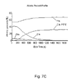
- FIG. 7 shows the results of etching and depth profiling on a PTFE surface.
- FIG. 1 there is shown a schematic view from the side of an ion gun 1 according to the present invention.
- the ion gun in use is fixed to a port of a UHV analysis chamber (not shown) by means of flange 22 , which in this case is a UHV conflat flange.
- a sample 24 in line of sight of the ion gun 1 .
- the pressure in the UHV Chamber is less than 10 ⁇ 6 mbar and is typically 2 ⁇ 10 ⁇ 7 mbar for XPS analysis for example.
- the UHV chamber is configured with analysis tools to enable XPS and optionally AES and/or other surface analysis to be performed on the sample 24 .
- the ion gun according to the invention is fully compatible with use on a high or ultra-high vacuum environment. In preferred embodiments for such use, the ion gun is bakeable and may be baked-out together with the vacuum chamber before use.
- the ion gun 1 is generally in the form of a column having a series of components arranged as now described.
- the ion gun has at its upstream end a high pressure source chamber 4 and argon gas is introduced, e.g. from a pressurised gas cylinder (not shown), into the source chamber 4 through a gas inlet in the form of gas inlet pipe 2 .
- Argon is the preferred gas for use with the ion gun but other gases may be used and mixtures of gases may also be used.
- the pressure of argon in the inlet and source chamber 4 is about 4 bar.
- a gas expansion nozzle 6 shaped and dimensioned for supersonic expansion of the argon from the source chamber 4 through the nozzle.
- the nozzle is a microfabricated metal nozzle and its shape is shown in more detail in FIG. 3 .
- the nozzle 6 as shown in FIG. 3 has a conical shaped inlet 16 at its end in the source chamber 4 and a conical shaped outlet 18 terminating in a pumped vacuum chamber 10 , the outlet 18 having a 5 degree half angle taper.
- the inlet and outlet are connected by an aperture 14 of 100 microns diameter or less.
- other shapes of nozzle may be used, such as a laval nozzle or a sonic nozzle, the latter consisting of an open aperture without any shaped section to contain the gas flow.
- the argon is expanded through the nozzle 6 into the pumped vacuum chamber 10 which is continuously pumped by a vacuum pump (not shown) to a rough vacuum of about 0.5 mbar or less, the chamber 10 being pumped through pumping aperture 12 .
- a vacuum pump not shown
- the expanding gas cools rapidly and clusters of argon atoms are formed.
- the gas forms a beam as it is accelerated to supersonic speed by its expansion, creating a mach disk at a distance from the nozzle.
- Clusters and non-clustered individual atoms are extracted from the centre of the expanding beam, just prior to the Mach disk, using a skimmer 20 of a conical profile carefully designed to minimise disruption of the supersonic beam.
- a second stage of differential pumping is employed in the form of pumped vacuum chamber 28 , which is continuously pumped by a vacuum pump (not shown) to a medium vacuum of less than 10 ⁇ 3 mbar, typically 4 ⁇ 10 ⁇ 4 mbar, the chamber 28 being pumped through pumping aperture 32 .
- the beam passes through a small aperture in a collimator cone 34 into an ionisation chamber 38 .
- the ionisation chamber 38 as well as the downstream ion optics and mass selection stage, is continuously pumped to high vacuum through pumping aperture 33 wherein the pressure is less than 10 ⁇ 4 mbar and is typically 10 ⁇ 5 mbar.
- thermally generated electrons from heated filaments 42 are injected into the ionisation Chamber by biasing the filaments 42 at a negative potential, in this case 100 volts, with respect to the chamber.
- a negative potential in this case 100 volts
- a fraction of both the clusters and the individual argon atoms in the ionisation chamber thereby are ionised by electron impact to produce positively charged ions.
- a positive voltage of 4 keV is applied to the ionisation chamber in which the ions are created and this positive voltage determines the final energy of the ions when they reach the surface of the sample 24 . This voltage is therefore termed the source voltage.
- the surface 24 which is irradiated by the ion beam is held at ground potential in this case.
- Ions of argon clusters of wide range of sizes as well as ions of individual argon atoms are present in the beam and are extracted from the ionisation chamber 38 further downstream in the ion gun column by an extraction electrode or lens 44 to which is applied a potential slightly more negative than the ionisation chamber 38 .
- the ions are focussed by a condenser lens 46 into a beam aperture 48 of 3 mm diameter which defines the effective size of the ion beam. In operation, de-focussing using the condenser lens can allow the ion beam current to be reduced if required.
- the beam of ions then enters a mass selector indicated generally at 50 .
- the mass selector comprises an electrically floating flight tube 52 situated within the magnetic field B of a magnetic sector comprising a soft iron magnet mounted outside of the vacuum system of the ion gun (not shown).
- the magnetic field B is aligned transverse to the direction of flight of the ion beam through the flight tube 52 .
- the magnetic field B is directed into the paper as indicted by the +symbols.
- the magnetic field B is programmable by means of an electromagnet 54 mounted outside the vacuum system which produces the transverse magnetic field.
- the magnetic sector is programmed using the electromagnet to deflect ions of the chosen mass so as to select at a selection aperture 60 a beam substantially comprising argon clusters of a selected size (mass) or substantially comprising atomic argon ions as described in more detail below.
- the energy of the ions passing through the flight tube will be at the full source energy defined by the source voltage. Any mass selection by magnetic fields that is performed in such an ion optical design must be designed to operate at this energy.
- the flight tube 52 can be floated to a voltage which is independent of the source voltage.
- the beam defining aperture 48 and all sections of the flight tube 52 can be floated to a voltage which is independent of the source voltage.
- a “softer” polymer material is to be etched, it is chosen to float the flight tube 52 at a voltage which is 1 kV less than the source voltage in order to generate a beam with an energy of 1 keV within the flight tube (e.g. using a source voltage of 4 keV and a flight tube voltage of 3 keV).
- the cluster ions pass through the flight tube 52 at a lower energy than that of the source energy making the design of the mass selector and its optics much simpler.
- a lower strength magnetic field may be used to achieve selection of clusters of the required mass.
- the floating flight tube 52 can be used to accelerate the ions for mass selection.
- the use of the flight tube to adjust the ion energy as appropriate and independently of the source energy allows improved flexibility in the design of the mass selector.
- By programming the electromagnet 54 with a lower current (and thus lower magnetic field) atomic argon ions can be selected to form the beam through the selection aperture 60 in order to enable etching of “harder” materials.
- Overall the design of the present invention enables a lower strength magnetic field to be used for the selection of either clusters or atomic ions because of the additional use of the floating flight tube to adjust the energy of the ions within the mass selector, especially for example to reduce the energy of the ions when selecting a beam of clusters.
- the prior art designs would instead require impractical and costly wide range magnetic field scanning to achieve a similar effect.
- the prior art mass selector designs would be impractical because to achieve the required magnetic field they would be too big and heavy to be mounted from a port on a typical XPS analysis chamber. Generating higher magnetic fields may also require the use of more expensive magnetic alloys which may be costly. In contrast, the mass selector of the present invention may be implemented using only a soft iron magnet.
- the flight tube 52 forms part of the mass selector, and the electromagnet 54 of the magnetic sector (not shown) mounted outside the vacuum system produces a transverse magnetic field B.
- the electromagnet is programmed to deflect a beam of cluster ions 72 of the chosen mass (typically with a mass above a lower mass limit of 200-2000 atoms) through an angle of 2 degrees to exit though the selection aperture 60 . Ions of lower mass 74 are deflected through a larger angle and do not pass through the selection aperture 60 . Ions of a higher mass 76 are deflected through a smaller angle and, if sufficiently massive, will not pass through the aperture 60 .
- the incorporation of the 2 degree deflection into the design of the ion gun column ensures that neutral clusters and atoms (e.g. non-ionised species or species formed by fragmentation of larger clusters) will not pass through the aperture 60 as they are not deflected by the magnetic field. Without the removal of neutral species in this way, such species, if of low enough mass, could cause significant damage to the sample. Neutral species of high mass which may not cause sample damage may still lead to non-uniform etching of the sample since they cannot be scanned by the deflection electrodes. This important benefit is not possible using a permanent magnet as the mass filter.
- the mass selector described in the shown embodiments may thus provide a band pass filter.
- the mass selected ions After passing through the selection aperture 60 , the mass selected ions pass through pairs of scanning deflectors or deflection electrodes 62 , 64 for positioning the beam and/or performing a rastering or scanning function of the beam at the sample surface and finally pass through an objective lens 68 to focus the beam at the sample 24 . After passing the objective lens, the energy of the beam returns to its original source voltage.
- the deflectors 62 , 64 and focussing objective lens 68 are used together to focus and scan the beam in a raster pattern over the surface of sample 24 to ensure uniform etching over a crater which is larger than the beam size.
- this technique is preferable to using a large area unfocused beam, although such an unfocused beam may be suitable in simple applications such as sample cleaning.
- a system computer 110 controls various high voltage power supplies 114 for the components via a Power Supply Interface 112 to which the computer is connected via a USB interface.
- the Power Supply Interface 112 also controls the filament current and magnet current to the magnetic winding of the electromagnet.
- Typical operating conditions that can be used for each mode of operation for the ion gun described with reference to FIGS. 1 to 4 are as follows.
- the ion gun may be used to clean a surface prior to a surface analysis or it may be used to etch a sample to a desired depth.
- the ion gun may be suitable for depth profiling XPS measurements, wherein XPS analysis is performed on a region of the sample surface whilst concurrently etching the surface in that region using the ion gun of the present invention to increase the depth of the XPS analysis and thereby to reveal the composition of the sample in depth direction.
- the present ion gun enables such depth profiling to be performed on soft or hard samples by the appropriate selection of either a cluster ion beam or atomic ion beam.
- the energy per atom required to etch the surface without significant damage thereto is typically from a few eV to several tens of eV while for harder materials it may be much higher and an atomic ion beam may be selected.
- the ability to tune the ion energy to the material to be etched allows the user to optimize the profile for the chemical information to be obtained.
- FIG. 6 there are shown XPS results on a silicon wafer having initially a thin film of Silicon Oxide thereon.
- the etch level is an arbitrary unit related to the depth of etching, which can be translated into a true “depth” once the etch rate is determined by using a calibrated sample.
- etch level is an arbitrary unit related to the depth of etching, which can be translated into a true “depth” once the etch rate is determined by using a calibrated sample.
- In the scan of un-etched wafer separate peaks can be seen for the pure un-oxidised silicon (large peak) and the silicon oxide (small peak).
- the ion gun was then set to its argon atomic ion mode and argon ions as ionised single argon atoms at a source energy of 4 keV irradiated the surface of the wafer to depth profile through the silicon oxide surface film.
- the XPS spectrum of the wafer after the depth profiling was completed shows only the un-oxidised silicon.
- the XPS depth profile in FIG. 6C shows the gradual removal of the adventitious carbon and the surface oxide. Depth profiling through such a relatively hard material as silicon and silicon oxide with merely a cluster ion beam would be very slow indeed.
- FIG. 7 there are shown XPS results for depth profiling on another very delicate sample, a fluoropolymer film on a PTFE substrate using the ion gun in its cluster mode with the same settings as Example 1. It is well known that PTFE is easily damaged by ion beam bombardment. As shown in FIG. 7A , before etching, and during the depth profile, a well resolved fluoropolymer spectrum is observed showing the details of the sample chemistry. After etching through the film, a spectrum as shown in FIG. 7B of the undamaged PTFE substrate is observed showing only the C—F2 bonded carbon of PTFE, with no peaks corresponding to any broken C—F or C—C bonds. The depth profile shown in FIG. 7C shows the transition through an undamaged fluoropolymer film into an undamaged PTFE film.
Landscapes
- Chemical & Material Sciences (AREA)
- Analytical Chemistry (AREA)
- Physics & Mathematics (AREA)
- Engineering & Computer Science (AREA)
- Immunology (AREA)
- Biochemistry (AREA)
- General Health & Medical Sciences (AREA)
- General Physics & Mathematics (AREA)
- Life Sciences & Earth Sciences (AREA)
- Pathology (AREA)
- Health & Medical Sciences (AREA)
- Combustion & Propulsion (AREA)
- Plasma & Fusion (AREA)
- Electron Sources, Ion Sources (AREA)
- Other Investigation Or Analysis Of Materials By Electrical Means (AREA)
- Physical Vapour Deposition (AREA)
Applications Claiming Priority (3)
| Application Number | Priority Date | Filing Date | Title |
|---|---|---|---|
| GB1017173.4 | 2010-10-12 | ||
| GB1017173.4A GB2484488B (en) | 2010-10-12 | 2010-10-12 | Improvements in and relating to ion guns |
| PCT/EP2011/067626 WO2012049110A2 (en) | 2010-10-12 | 2011-10-10 | Improvements in and relating to ion guns |
Publications (2)
| Publication Number | Publication Date |
|---|---|
| US20130180844A1 US20130180844A1 (en) | 2013-07-18 |
| US9478388B2 true US9478388B2 (en) | 2016-10-25 |
Family
ID=43304416
Family Applications (1)
| Application Number | Title | Priority Date | Filing Date |
|---|---|---|---|
| US13/823,499 Active 2033-02-28 US9478388B2 (en) | 2010-10-12 | 2011-10-10 | Switchable gas cluster and atomic ion gun, and method of surface processing using the gun |
Country Status (5)
| Country | Link |
|---|---|
| US (1) | US9478388B2 (https=) |
| JP (1) | JP5808815B2 (https=) |
| CN (1) | CN203466162U (https=) |
| GB (1) | GB2484488B (https=) |
| WO (1) | WO2012049110A2 (https=) |
Cited By (3)
| Publication number | Priority date | Publication date | Assignee | Title |
|---|---|---|---|---|
| US20160172197A1 (en) * | 2010-08-23 | 2016-06-16 | Exogenesis Corporation | Method and apparatus for neutral beam processing based on gas cluster ion beam technology and articles produced thereby |
| US10825685B2 (en) | 2010-08-23 | 2020-11-03 | Exogenesis Corporation | Method for neutral beam processing based on gas cluster ion beam technology and articles produced thereby |
| US11048162B2 (en) | 2010-08-23 | 2021-06-29 | Exogenesis Corporation | Method and apparatus for neutral beam processing based on gas cluster ion beam technology |
Families Citing this family (15)
| Publication number | Priority date | Publication date | Assignee | Title |
|---|---|---|---|---|
| JP2014086247A (ja) * | 2012-10-23 | 2014-05-12 | Canon Inc | 超音速ビーム装置 |
| US8963081B2 (en) * | 2013-03-06 | 2015-02-24 | Canon Kabushiki Kaisha | Mass selector, and ion gun, ion irradiation apparatus and mass microscope |
| US8993982B2 (en) | 2013-07-15 | 2015-03-31 | Vg Systems Limited | Switchable ion gun with improved gas inlet arrangement |
| JP2015138667A (ja) * | 2014-01-22 | 2015-07-30 | アルバック・ファイ株式会社 | イオン源、イオン銃、分析装置 |
| CN103956314B (zh) * | 2014-05-04 | 2016-02-17 | 北京大学 | 一种微波驱动无铯负氢离子源 |
| JP6566683B2 (ja) * | 2014-07-02 | 2019-08-28 | 東京エレクトロン株式会社 | 基板洗浄方法および基板洗浄装置 |
| JP6331960B2 (ja) * | 2014-10-21 | 2018-05-30 | 住友金属鉱山株式会社 | 薄膜状の試料の前処理方法および分析方法 |
| US11127909B2 (en) | 2016-03-24 | 2021-09-21 | Sony Corporation | Photoelectric conversion element, measuring method of the same, solid-state imaging device, electronic device, and solar cell |
| JP6632937B2 (ja) * | 2016-06-27 | 2020-01-22 | アールエムテック株式会社 | ガスクラスタービーム装置 |
| CN107121694A (zh) * | 2017-05-26 | 2017-09-01 | 宜昌后皇真空科技有限公司 | 一种在线监测脉冲气体团簇离子束的方法及系统 |
| CN107393794B (zh) * | 2017-08-07 | 2019-09-10 | 深圳江海行纳米科技有限公司 | 一种气体团簇离子源产生方法及装置 |
| CN109862684B (zh) * | 2018-12-21 | 2020-07-10 | 南京大学 | 单一尺寸强流团簇脉冲束产生方法 |
| EP3705877A1 (en) * | 2019-03-04 | 2020-09-09 | VG Systems Limited | Methods and apparatus for electron backscatter diffraction sample characterisation |
| CN110473765B (zh) * | 2019-08-30 | 2024-04-26 | 西安交通大学 | 一种表面活化过程中高速氩原子束获得装置及获得方法 |
| CN117012314B (zh) * | 2023-08-11 | 2025-09-16 | 中国科学院深圳先进技术研究院 | 一种团簇动力学性质的表征分析方法、系统、电子设备及存储介质 |
Citations (11)
| Publication number | Priority date | Publication date | Assignee | Title |
|---|---|---|---|---|
| US4755344A (en) * | 1980-04-11 | 1988-07-05 | The United States Of America As Represented By The United States Department Of Energy | Method and apparatus for the production of cluster ions |
| US4831308A (en) * | 1986-09-25 | 1989-05-16 | Sony Corporation | Ion beam gun wherein the needle emitter is surrounded by a tubular nozzle so as to produce an increased ion beam |
| JPH08122283A (ja) | 1994-10-20 | 1996-05-17 | Matsushita Electric Ind Co Ltd | 表面分析方法 |
| US6222185B1 (en) * | 1996-06-10 | 2001-04-24 | Micromass Limited | Plasma mass spectrometer |
| US20010033128A1 (en) * | 1999-12-06 | 2001-10-25 | Torti Richard P. | Gas cluster ion beam low mass ion filter |
| US20050082497A1 (en) | 2003-10-17 | 2005-04-21 | Applied Materials, Inc. | Ion implanter electrodes |
| US20060169915A1 (en) | 2004-11-12 | 2006-08-03 | Varian Semiconductor Equipment Associates, Inc. | Ion source configuration for production of ionized clusters, ionized molecules and ionized mono-atoms |
| WO2006127327A2 (en) | 2005-05-20 | 2006-11-30 | Purser Kenneth H | A resonance method for production of intense low-impurity ion beams of atoms and molecules |
| US20070170372A1 (en) | 1999-12-13 | 2007-07-26 | Semequip, Inc. | Dual mode ion source for ion implantation |
| US20080105833A1 (en) | 2006-11-08 | 2008-05-08 | Varian Semiconductor Equipment Associates, | Ion implantation device with a dual pumping mode and method thereof |
| US20100155619A1 (en) * | 2008-12-22 | 2010-06-24 | Varian Semiconductor Equipment Associates Inc. | Directional gas injection for an ion source cathode assembly |
Family Cites Families (7)
| Publication number | Priority date | Publication date | Assignee | Title |
|---|---|---|---|---|
| US4847504A (en) * | 1983-08-15 | 1989-07-11 | Applied Materials, Inc. | Apparatus and methods for ion implantation |
| GB2386747A (en) | 2001-11-08 | 2003-09-24 | Ionoptika Ltd | Fullerene ion gun |
| JP4497889B2 (ja) | 2003-10-29 | 2010-07-07 | アルバック・ファイ株式会社 | 電子分光分析方法及び分析装置 |
| JP2006032229A (ja) * | 2004-07-20 | 2006-02-02 | Nissin Ion Equipment Co Ltd | イオン注入装置 |
| JP2008116363A (ja) | 2006-11-06 | 2008-05-22 | Ulvac Japan Ltd | 表面分析方法 |
| JPWO2009131022A1 (ja) | 2008-04-23 | 2011-08-18 | 株式会社アルバック | 分析方法 |
| GB2460855B (en) | 2008-06-11 | 2013-02-27 | Kratos Analytical Ltd | Electron spectroscopy |
-
2010
- 2010-10-12 GB GB1017173.4A patent/GB2484488B/en active Active
-
2011
- 2011-10-10 CN CN201190000794.1U patent/CN203466162U/zh not_active Expired - Lifetime
- 2011-10-10 WO PCT/EP2011/067626 patent/WO2012049110A2/en not_active Ceased
- 2011-10-10 US US13/823,499 patent/US9478388B2/en active Active
- 2011-10-10 JP JP2013533165A patent/JP5808815B2/ja active Active
Patent Citations (11)
| Publication number | Priority date | Publication date | Assignee | Title |
|---|---|---|---|---|
| US4755344A (en) * | 1980-04-11 | 1988-07-05 | The United States Of America As Represented By The United States Department Of Energy | Method and apparatus for the production of cluster ions |
| US4831308A (en) * | 1986-09-25 | 1989-05-16 | Sony Corporation | Ion beam gun wherein the needle emitter is surrounded by a tubular nozzle so as to produce an increased ion beam |
| JPH08122283A (ja) | 1994-10-20 | 1996-05-17 | Matsushita Electric Ind Co Ltd | 表面分析方法 |
| US6222185B1 (en) * | 1996-06-10 | 2001-04-24 | Micromass Limited | Plasma mass spectrometer |
| US20010033128A1 (en) * | 1999-12-06 | 2001-10-25 | Torti Richard P. | Gas cluster ion beam low mass ion filter |
| US20070170372A1 (en) | 1999-12-13 | 2007-07-26 | Semequip, Inc. | Dual mode ion source for ion implantation |
| US20050082497A1 (en) | 2003-10-17 | 2005-04-21 | Applied Materials, Inc. | Ion implanter electrodes |
| US20060169915A1 (en) | 2004-11-12 | 2006-08-03 | Varian Semiconductor Equipment Associates, Inc. | Ion source configuration for production of ionized clusters, ionized molecules and ionized mono-atoms |
| WO2006127327A2 (en) | 2005-05-20 | 2006-11-30 | Purser Kenneth H | A resonance method for production of intense low-impurity ion beams of atoms and molecules |
| US20080105833A1 (en) | 2006-11-08 | 2008-05-08 | Varian Semiconductor Equipment Associates, | Ion implantation device with a dual pumping mode and method thereof |
| US20100155619A1 (en) * | 2008-12-22 | 2010-06-24 | Varian Semiconductor Equipment Associates Inc. | Directional gas injection for an ion source cathode assembly |
Non-Patent Citations (4)
| Title |
|---|
| Datasheet-Ion gun from Ionoptika:http://www.ionoptika.com/products/ion-beams/gas-cluster-ion-beams/81- products/ion-beams/gas-cluster-ion-beams/92-gcib-10.html, downloaded Jul. 10, 2013, 3 pages. |
| Datasheet-Ion gun from Kratos:http://surface.kratos.com/Depth-Profiling/argon-gas-cluster-ion-source/Hardware.html, downloaded Jul. 10, 2013, 5 pages. |
| Matsuo, J., et al., "Gas cluster ion beam equipments for industrial applications," Nuclear Instruments & Methods in Physics Research, Section B (Beam Interactions with Materials and Atoms), Netherlands, vol. 899, No. 1-4, May 1995, pp. 244-247. |
| Yamada, I., "Characteristics and peculiarities of surface processing by gas cluster ion beams," Nuclear Instruments & Methods in Physics Research, Section B (Beam Interactions with Materials and Atoms), Elsevier, Amsterdam, NL, vol. 112, No. 1, May 1996, pp. 242-247. |
Cited By (4)
| Publication number | Priority date | Publication date | Assignee | Title |
|---|---|---|---|---|
| US20160172197A1 (en) * | 2010-08-23 | 2016-06-16 | Exogenesis Corporation | Method and apparatus for neutral beam processing based on gas cluster ion beam technology and articles produced thereby |
| US10181402B2 (en) * | 2010-08-23 | 2019-01-15 | Exogenesis Corporation | Method and apparatus for neutral beam processing based on gas cluster ion beam technology and articles produced thereby |
| US10825685B2 (en) | 2010-08-23 | 2020-11-03 | Exogenesis Corporation | Method for neutral beam processing based on gas cluster ion beam technology and articles produced thereby |
| US11048162B2 (en) | 2010-08-23 | 2021-06-29 | Exogenesis Corporation | Method and apparatus for neutral beam processing based on gas cluster ion beam technology |
Also Published As
| Publication number | Publication date |
|---|---|
| GB201017173D0 (en) | 2010-11-24 |
| WO2012049110A2 (en) | 2012-04-19 |
| JP2013541165A (ja) | 2013-11-07 |
| WO2012049110A3 (en) | 2012-06-28 |
| US20130180844A1 (en) | 2013-07-18 |
| JP5808815B2 (ja) | 2015-11-10 |
| GB2484488A (en) | 2012-04-18 |
| CN203466162U (zh) | 2014-03-05 |
| GB2484488B (en) | 2013-04-17 |
Similar Documents
| Publication | Publication Date | Title |
|---|---|---|
| US9478388B2 (en) | Switchable gas cluster and atomic ion gun, and method of surface processing using the gun | |
| JP4926067B2 (ja) | ガスクラスターイオンビーム形成のためのイオナイザおよび方法 | |
| US8993982B2 (en) | Switchable ion gun with improved gas inlet arrangement | |
| CN104380425B (zh) | 多种类离子源 | |
| US7696495B2 (en) | Method and device for adjusting a beam property in a gas cluster ion beam system | |
| US9305746B2 (en) | Pre-aligned nozzle/skimmer | |
| TWI732817B (zh) | 離子束裝置中汙染控制的裝置和方法 | |
| US11004649B2 (en) | Ion source device | |
| KR100445105B1 (ko) | 가스 클러스터 이온빔을 이용한 아이.티.오 박막 표면처리시스템 및 그 방법 | |
| JP4977008B2 (ja) | 高電流ガスクラスターイオンビーム処理システムにおけるビーム安定性向上方法及び装置 | |
| US9691583B2 (en) | Imaging and processing for plasma ion source | |
| KR102682681B1 (ko) | 고-전류 이온 주입기 및 고-전류 이온 주입기를 사용하여 이온 빔을 제어하기 위한 방법 | |
| JP2019149370A (ja) | 荷電粒子ソース及びバックスパッタリングを利用した荷電粒子ソースのクリーニング方法 | |
| US20090166555A1 (en) | RF electron source for ionizing gas clusters | |
| US20070010095A1 (en) | Surface treatment method using ion beam and surface treating device | |
| JP6441702B2 (ja) | イオン源、イオンビーム装置および試料の加工方法 | |
| JP6637146B2 (ja) | イオンビーム装置および試料の3次元構造解析方法 |
Legal Events
| Date | Code | Title | Description |
|---|---|---|---|
| AS | Assignment |
Owner name: VG SYSTEMS LIMITED, UNITED KINGDOM Free format text: ASSIGNMENT OF ASSIGNORS INTEREST;ASSIGNOR:BARNARD, BRYAN;REEL/FRAME:030163/0019 Effective date: 20130107 |
|
| STCF | Information on status: patent grant |
Free format text: PATENTED CASE |
|
| MAFP | Maintenance fee payment |
Free format text: PAYMENT OF MAINTENANCE FEE, 4TH YEAR, LARGE ENTITY (ORIGINAL EVENT CODE: M1551); ENTITY STATUS OF PATENT OWNER: LARGE ENTITY Year of fee payment: 4 |
|
| MAFP | Maintenance fee payment |
Free format text: PAYMENT OF MAINTENANCE FEE, 8TH YEAR, LARGE ENTITY (ORIGINAL EVENT CODE: M1552); ENTITY STATUS OF PATENT OWNER: LARGE ENTITY Year of fee payment: 8 |