US9469448B2 - Container and lid locking mechanism thereof - Google Patents
Container and lid locking mechanism thereof Download PDFInfo
- Publication number
- US9469448B2 US9469448B2 US14/422,115 US201314422115A US9469448B2 US 9469448 B2 US9469448 B2 US 9469448B2 US 201314422115 A US201314422115 A US 201314422115A US 9469448 B2 US9469448 B2 US 9469448B2
- Authority
- US
- United States
- Prior art keywords
- lid
- locking
- side plates
- locking mechanism
- container
- Prior art date
- Legal status (The legal status is an assumption and is not a legal conclusion. Google has not performed a legal analysis and makes no representation as to the accuracy of the status listed.)
- Active
Links
- 230000007246 mechanism Effects 0.000 title claims abstract description 48
- 230000013011 mating Effects 0.000 claims description 13
- 239000007788 liquid Substances 0.000 description 3
- 238000000034 method Methods 0.000 description 3
- 230000008569 process Effects 0.000 description 3
- 230000001186 cumulative effect Effects 0.000 description 2
- 230000009471 action Effects 0.000 description 1
- 238000009434 installation Methods 0.000 description 1
- 238000012986 modification Methods 0.000 description 1
- 230000004048 modification Effects 0.000 description 1
- 230000007306 turnover Effects 0.000 description 1
Images


Classifications
-
- B—PERFORMING OPERATIONS; TRANSPORTING
- B65—CONVEYING; PACKING; STORING; HANDLING THIN OR FILAMENTARY MATERIAL
- B65D—CONTAINERS FOR STORAGE OR TRANSPORT OF ARTICLES OR MATERIALS, e.g. BAGS, BARRELS, BOTTLES, BOXES, CANS, CARTONS, CRATES, DRUMS, JARS, TANKS, HOPPERS, FORWARDING CONTAINERS; ACCESSORIES, CLOSURES, OR FITTINGS THEREFOR; PACKAGING ELEMENTS; PACKAGES
- B65D43/00—Lids or covers for rigid or semi-rigid containers
- B65D43/14—Non-removable lids or covers
- B65D43/22—Devices for holding in closed position, e.g. clips
-
- B—PERFORMING OPERATIONS; TRANSPORTING
- B65—CONVEYING; PACKING; STORING; HANDLING THIN OR FILAMENTARY MATERIAL
- B65D—CONTAINERS FOR STORAGE OR TRANSPORT OF ARTICLES OR MATERIALS, e.g. BAGS, BARRELS, BOTTLES, BOXES, CANS, CARTONS, CRATES, DRUMS, JARS, TANKS, HOPPERS, FORWARDING CONTAINERS; ACCESSORIES, CLOSURES, OR FITTINGS THEREFOR; PACKAGING ELEMENTS; PACKAGES
- B65D19/00—Pallets or like platforms, with or without side walls, for supporting loads to be lifted or lowered
- B65D19/02—Rigid pallets with side walls, e.g. box pallets
- B65D19/06—Rigid pallets with side walls, e.g. box pallets with bodies formed by uniting or interconnecting two or more components
-
- B—PERFORMING OPERATIONS; TRANSPORTING
- B65—CONVEYING; PACKING; STORING; HANDLING THIN OR FILAMENTARY MATERIAL
- B65D—CONTAINERS FOR STORAGE OR TRANSPORT OF ARTICLES OR MATERIALS, e.g. BAGS, BARRELS, BOTTLES, BOXES, CANS, CARTONS, CRATES, DRUMS, JARS, TANKS, HOPPERS, FORWARDING CONTAINERS; ACCESSORIES, CLOSURES, OR FITTINGS THEREFOR; PACKAGING ELEMENTS; PACKAGES
- B65D77/00—Packages formed by enclosing articles or materials in preformed containers, e.g. boxes, cartons, sacks or bags
- B65D77/04—Articles or materials enclosed in two or more containers disposed one within another
- B65D77/06—Liquids or semi-liquids or other materials or articles enclosed in flexible containers disposed within rigid containers
- B65D77/061—Liquids or semi-liquids or other materials or articles enclosed in flexible containers disposed within rigid containers the containers being mounted on a pallet
-
- B—PERFORMING OPERATIONS; TRANSPORTING
- B65—CONVEYING; PACKING; STORING; HANDLING THIN OR FILAMENTARY MATERIAL
- B65D—CONTAINERS FOR STORAGE OR TRANSPORT OF ARTICLES OR MATERIALS, e.g. BAGS, BARRELS, BOTTLES, BOXES, CANS, CARTONS, CRATES, DRUMS, JARS, TANKS, HOPPERS, FORWARDING CONTAINERS; ACCESSORIES, CLOSURES, OR FITTINGS THEREFOR; PACKAGING ELEMENTS; PACKAGES
- B65D2251/00—Details relating to container closures
-
- B—PERFORMING OPERATIONS; TRANSPORTING
- B65—CONVEYING; PACKING; STORING; HANDLING THIN OR FILAMENTARY MATERIAL
- B65D—CONTAINERS FOR STORAGE OR TRANSPORT OF ARTICLES OR MATERIALS, e.g. BAGS, BARRELS, BOTTLES, BOXES, CANS, CARTONS, CRATES, DRUMS, JARS, TANKS, HOPPERS, FORWARDING CONTAINERS; ACCESSORIES, CLOSURES, OR FITTINGS THEREFOR; PACKAGING ELEMENTS; PACKAGES
- B65D2519/00—Pallets or like platforms, with or without side walls, for supporting loads to be lifted or lowered
- B65D2519/00004—Details relating to pallets
- B65D2519/00258—Overall construction
- B65D2519/00313—Overall construction of the base surface
- B65D2519/00328—Overall construction of the base surface shape of the contact surface of the base
- B65D2519/00333—Overall construction of the base surface shape of the contact surface of the base contact surface having a stringer-like shape
-
- B—PERFORMING OPERATIONS; TRANSPORTING
- B65—CONVEYING; PACKING; STORING; HANDLING THIN OR FILAMENTARY MATERIAL
- B65D—CONTAINERS FOR STORAGE OR TRANSPORT OF ARTICLES OR MATERIALS, e.g. BAGS, BARRELS, BOTTLES, BOXES, CANS, CARTONS, CRATES, DRUMS, JARS, TANKS, HOPPERS, FORWARDING CONTAINERS; ACCESSORIES, CLOSURES, OR FITTINGS THEREFOR; PACKAGING ELEMENTS; PACKAGES
- B65D2519/00—Pallets or like platforms, with or without side walls, for supporting loads to be lifted or lowered
- B65D2519/00004—Details relating to pallets
- B65D2519/00547—Connections
- B65D2519/00706—Connections structures connecting the lid or cover to the side walls or corner posts
- B65D2519/00711—Connections structures connecting the lid or cover to the side walls or corner posts removable lid or covers
Definitions
- the present invention relates to containers, in particular to a locking mechanism to lock a container lid to a container.
- a large container generally has four side plates and a base, and a lid is also provided for a large container used in transport of bulks or liquids so as to protect the cargo inside the container.
- the edgeguard of the lid will prevent the four side plates from deforming too large.
- the lid will limit the fluctuating of a liner containing the liquids or bulks, thus preventing the liner from being damaged.
- the lid should be connected to the container reliably when used.
- the four side plates of the large container can be subsequently folded so as to reduce the space occupied when not in use, thus reduce the costs of turnover and warehousing of products. Further, when the lid is placed on the folded container, the mechanism of lid connected to the container should avoid accumulating high altitude.
- One of current locking means for locking a lid to a container comprises a latch and a pit on the upper edge of the lid to accommodate the latch.
- a hole is provided on the sidewall of the pit through which the latch will extend into a groove on a side plate of the container.
- the aim of the present invention is to provide a lid locking mechanism of a container which will not be damaged easily, and it is very convenient to open and close the lid provided with the locking mechanism.
- a lid locking mechanism of a container includes a base, side plates and a lid, wherein said locking mechanism is provided on an edge of the lid and an upper portion of the side plate; and said locking mechanism comprises a locking structure, a restoring structure and a guiding structure; wherein said locking structure is used to lock the lid to the side plates of the container, and said restoring structure and said guiding structure are used to assist the locking structure in locking the lid to the side plates.
- said locking mechanism includes a handle, a spring, a pit provided on the edge of the lid and a recess provided on the side plate; wherein a latch is provided on said handle, and said handle and the spring are accommodated in the pit of the lid; said latch is engaged with the pit of the side plate so as to lock the lid to the side plate; and said spring applies a restoring force to the handle.
- a hole is provided on a side wall of the pit of the lid; a sliding rail opposed to the hole is provided inside the pit; and between the sliding rail and the hole there is a rib for accommodating the spring.
- the latch is provided on one end of the handle and used to be engaged with the hole and the other end of the handle is provided with a sliding slot for engaging with the sliding rail; and the back portion of the handle is provided with an elongate slot, and a pin is provided on a side wall of the slot, wherein the elongate slot together with the rib are used to accommodate the spring.
- a side of the handle is provided with a notch.
- said locking structure is a locking member; said restoring structure is a torsional spring; and said guiding structure is comprised of grooves on the lid and a mating structure on the side plate; wherein said locking member is installed in the mating structure and enters or leaves the groove so as to open or close the lid.
- the spring is fitted to said locking member and said locking member is provided with a rotation pin, a bearing pin and two position limiting pins, wherein one of the position limiting pins is provided with a projection;
- said mating structure comprises pits on both ends of the upper portion of the side plate, wherein a circular hole, a special-shaped through-hole with a special arced contour, and a position limiting hole are provided at each pit;
- the rotation pin when mounting the locking member to the side plate, the rotation pin is inserted into the circular hole and the two position limiting pins are inserted into the special-shaped through-hole and the position limiting hole respectively so as to hold the locking member on the mating structure;
- the bearing pin When the lid slids on the side plates, the bearing pin will enter or leave the groove so as to locked or unlocked the lid.
- the grooves are provided on the left and right ends of an edgeguard of the lid; and a slope is provided at the outer side of each groove and a dimple is provided inside the groove, wherein an arced contour is provided on the bottom the dimple.
- the present invention also provides a container, which comprising a base, side plates and a lid, wherein the container further comprises a lid locking mechanism according to the above embodiments.
- the locking mechanism is located on the edge of the lid or the upper portion of the side plates and has compact structure. Therefore, it helps to reduce the cumulative height of lid and the container folded and the costs of the transportation and warehousing are also reduced.
- the locking mechanism further includes a restoring member and a guiding member, such that when the lid is placed on the container, whether it is in a closed state or opened state, the locking mechanism will not be easily damaged, and it is very convenient to open and close the lid.
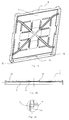
- FIG. 1 is a perspective structural view of a common container
- FIG. 2 a shows a perspective structural view of a lid provided with the lid locking mechanism according to the first embodiment of the present invention
- FIG. 2 b shows a cross-sectional view of the lid provided with the lid locking mechanism according to the first embodiment of the present invention
- FIG. 2 c shows an enlarged cross-sectional view of the part A of the lid in FIG. 2 b;
- FIG. 3 shows a perspective view of a locking member of the lid locking mechanism according to the first embodiment of the present invention
- FIG. 4 a shows a front view of a mating structure of the lid locking mechanism according to the first embodiment of the present invention provided on the upper portion of a side plate;
- FIG. 4 b shows an enlarged perspective view of the mating structure in FIG. 4 a;
- FIG. 5 shows the process of the locking member entering a groove on the lid when the lid is placed on the container from directly above the container, according to the first embodiment of the present invention
- FIG. 6 shows a perspective structural view of the container provided with a lid locking mechanism according to the second embodiment of the present invention
- FIG. 7 shows the structure of the lid using the lid locking mechanism according to the second embodiment of the present invention.
- FIGS. 7 a and 7 b show enlarged views of parts B and C in FIG. 7 respectively;
- FIGS. 8 a and 8 b are perspective structural view of a handle of the lid locking mechanism according the second embodiment of the present invention.
- FIGS. 9 and 10 show a state when the lid is placed on the container but not fully closed, wherein FIG. 10 is an enlarged view of part D in FIG. 9 ;
- FIG. 12 shows a partial cross-sectional view of the lid locking mechanism when the lid is locked to the container.
- FIG. 1 shows a general structure of a large container including a lid 1 , a base 2 , side plates 3 , 4 , 5 , 6 and a small door 7 .
- the edgeguard around the lid will contact (surround) the outer surfaces of side plates 3 , 4 , 5 , 6 so as to improve the strength of the entire container.
- FIGS. 2 a - 5 show schematic structure views of the lid locking mechanism of a large container according to the first embodiment of the present invention.
- the lid locking mechanism includes a groove 12 provided on the lid 1 , a locking member 8 as a separate member, and mating structures provided on the side plate for engaging with the lid 1 and the locking member 8 , wherein the mating structures provided on the side plate are engaged with the lid 1 and the locking member 8 so as to close or open the lid.
- FIGS. 2 a -2 c show the structure of the lid 1 according to the embodiment.
- grooves are provided on the right and left end of an edgeguard 1 a of the lid 1 on inner surface thereof respectively.
- a slope 122 is provided at outer side of each groove 12 so as to provide a guide for the locking member (which will be described in more detail hereinafter).
- a dimple 121 is provided inside the groove 12 , wherein an arced contour is provided on the bottom of the dimple.
- a groove 12 is also provided on the left and right end of another edgeguard 1 b .
- only one groove may be provided on each edgeguard of edgeguards 1 a and 1 b.
- FIG. 3 is a perspective view of the locking member 8 with a torsional spring 9 thereon.
- the locking member 8 comprises a rotation pin 83 , a bearing pin 81 , a position limiting pin 82 and a position limiting pin 84 , wherein the position limiting pin 84 is further provided with a projection 841 .
- the function of the projection 841 will be described in detail in the following.
- the torsional spring 9 is installed on the rotation pin 83 .
- FIGS. 4 a -4 b are partial side views of the side plate 6 , which has two pits 61 on both ends of its upper portion, wherein a circular hole 63 and a special-shaped through-hole 64 with a special arced contour 641 are provided at each pit 61 .
- a stopping edge 65 is provided on the left of the circular hole 63 .
- the locking member 8 will lean against the stopping edge 65 since the torsional spring 9 will applied a counterclockwise torque to the locking member 8 continually. Now, the locking member will not able to be released due to the deviation of the arced contour 641 from the projection 841 .
- the locking member can be released only in the case that the projection 841 of the position limiting 84 is aligned with the arced contour 641 .
- corresponding structures are also provided at the side plate 4 opposed to the side plate 6 .
- FIG. 5 shows the process of the locking member 8 entering the groove 12 when the lid 1 is placed on the container from directly above the container.
- the slope 122 will contact with the bearing pin 81 of the locking member 8 firstly, and the locking member 8 will be forced to rotate an angle clockwise around its rotation pin 83 due to the pressure applied by the slope 122 , which makes the bearing pin 81 to leave the location under the groove 12 .
- the bearing pin 81 face exactly to the dimple 121 of the groove 12 .
- the locking member 8 will rotate counterclockwise around the rotation pin 83 due to the restore of the torsional spring 9 , so that the bearing pin 81 enters into the dimple 121 , thereby limiting the upward movement of the lid 1 .
- the lid 1 rotates by a certain angle around a position where the lid 1 contacts with the left and upper portion of the side plate 6 . Then, the bearing pin 81 of the lid locking member 8 will be released from the groove 12 when continuing to push the lid 1 forward so as to open the lid 1 .
- FIGS. 6-12 show perspective structural views of the lid locking mechanism provided at a large container according to the second embodiment of the present invention.
- the lid locking mechanism comprises a pit 14 provided at edge of the lid, a left handle 12 , a right handle 10 and a spring 11 .
- a square hole 141 (or polygon hole 141 ) is provided on one side wall of the pit 14
- a sliding rail 143 opposed to the hole 141 is provided inside the pit 14 , wherein the cross section of sliding rail 143 is I-shaped, but also may be other types, such as T-shaped.
- FIGS. 8 a -8 b show the right handle 10 of the lid locking mechanism.
- the left handle 12 will not be elaborated here since the structure and function of the left handle 12 are same as the right handle.
- one end of the right handle 10 is provided with a latch 103 with a slope 1031 and a sliding slot 101 is provided on the other end of the right handle 10 .
- the back portion of the handle 10 is provided with an elongate slot 102 with a small pin 1021 on its side wall.
- a notch 104 for facilitating gripping is further provided on the side portion of the handle 10 .
- FIGS. 9 and 10 show the state that the lid 1 is placed on the container but not fully closed, wherein FIG. 10 is an enlarged view of part D in FIG. 9 .
- FIG. 10 when the handle 10 is placed in the pit 14 of the lid 1 , the sliding rail 143 is engaged with the sliding slot 101 and the latch 103 passes through the square hole 141 .
- the spring 11 is placed within a cavity formed by the slot 102 of the right handle 10 and the rib 142 of the lid, wherein the pin 1021 assists in preventing the spring 11 from releasing from the slot 102 of the right handle 10 easily.
- the latch 103 of the handle 10 will tend to be always in a running out state due to the restore of the spring.
- the handle 10 When opening the lid 1 , the handle 10 is moved along the sliding rails so that the latch 103 is pushed out of the recess 41 of the side plate and then the lid 1 is lifted up so as to open the lid.
- the lid and the side plates can be provided with an appropriate number of the lid locking mechanisms if necessary.
- the locking mechanism is located on the edge of the lid or the upper portion of the side plates and has compact structure. Therefore, it helps to reduce the cumulative height of lid and the container folded and the costs of the transportation and warehousing are also reduced.
- the locking mechanism further includes a restoring member and a guiding member, such that when the lid is placed on the container, whether it is in a closed state or opened state, the locking mechanism will not be easily damaged, and it is very convenient to open and close the lid.
Landscapes
- Engineering & Computer Science (AREA)
- Mechanical Engineering (AREA)
- Closures For Containers (AREA)
Applications Claiming Priority (4)
| Application Number | Priority Date | Filing Date | Title |
|---|---|---|---|
| CN201210295537 | 2012-08-16 | ||
| CN201210295537.6 | 2012-08-16 | ||
| CN201210295537.6A CN102795436B (zh) | 2012-08-16 | 2012-08-16 | 容器盖子锁定机构及容器 |
| PCT/CN2013/081661 WO2014026646A1 (zh) | 2012-08-16 | 2013-08-16 | 容器盖子锁定机构及容器 |
Publications (2)
| Publication Number | Publication Date |
|---|---|
| US20150191281A1 US20150191281A1 (en) | 2015-07-09 |
| US9469448B2 true US9469448B2 (en) | 2016-10-18 |
Family
ID=47194787
Family Applications (1)
| Application Number | Title | Priority Date | Filing Date |
|---|---|---|---|
| US14/422,115 Active US9469448B2 (en) | 2012-08-16 | 2013-08-16 | Container and lid locking mechanism thereof |
Country Status (5)
| Country | Link |
|---|---|
| US (1) | US9469448B2 (pl) |
| EP (1) | EP2907771B1 (pl) |
| CN (1) | CN102795436B (pl) |
| PL (1) | PL2907771T3 (pl) |
| WO (1) | WO2014026646A1 (pl) |
Families Citing this family (10)
| Publication number | Priority date | Publication date | Assignee | Title |
|---|---|---|---|---|
| CN102795436B (zh) * | 2012-08-16 | 2014-04-30 | 上海鸿研物流技术有限公司 | 容器盖子锁定机构及容器 |
| CN103754516B (zh) * | 2014-01-13 | 2015-10-28 | 上海鸿研物流技术有限公司 | 容器盖子锁定机构及容器 |
| CN104960813B (zh) * | 2015-06-25 | 2018-05-01 | 上海鸿研物流技术有限公司 | 容器 |
| CN105438594B (zh) * | 2015-11-20 | 2018-07-10 | 上海鸿研物流技术有限公司 | 框架及托盘围板箱 |
| CN109484739B (zh) * | 2018-11-06 | 2024-05-28 | 中国人民解放军军事科学院国防工程研究院 | 一种便于取货的木质包装箱 |
| CN109573375B (zh) * | 2019-01-09 | 2024-04-02 | 上海鸿研物流技术有限公司 | 容器及其锁定装置 |
| CN109911404B (zh) * | 2019-01-22 | 2024-05-07 | 上海鸿研物流技术有限公司 | 容器 |
| CN110902136A (zh) * | 2019-12-09 | 2020-03-24 | 上海派瑞特塑业有限公司 | 一种周转箱盖锁定结构 |
| CN111169790B (zh) * | 2020-02-03 | 2025-04-01 | 上海箱箱智能科技有限公司 | 容器 |
| CN112124741B (zh) * | 2020-09-14 | 2025-06-27 | 中国国际海运集装箱(集团)股份有限公司 | 托盘箱 |
Citations (10)
| Publication number | Priority date | Publication date | Assignee | Title |
|---|---|---|---|---|
| US6367639B1 (en) * | 1999-03-29 | 2002-04-09 | Bob Mar | Safety container providing optional opening and closing arrangements |
| US6648162B1 (en) * | 2001-12-21 | 2003-11-18 | Innovation Ip Holding Co. | Button actuated pressure release and locking device for pressure cookers |
| US7108135B2 (en) * | 2002-01-28 | 2006-09-19 | Samsung Electronics Co., Ltd. | Workpiece container assembly and apparatus for opening/closing the same |
| US7255228B2 (en) * | 2004-07-29 | 2007-08-14 | Hana Cobi Co., Ltd. | Cellular phone casing with melted liquid flow disconnection hole along hinge line |
| WO2009121092A1 (en) | 2008-03-31 | 2009-10-08 | Edenshore Pty Ltd | Demountable container |
| US20100200581A1 (en) * | 2009-02-12 | 2010-08-12 | Maltz Lawrence J | Box that is held and opened with one hand |
| CN102092541A (zh) | 2010-12-23 | 2011-06-15 | 南车二七车辆有限公司 | 一种铁路平车运输集装箱用伸缩式旋转锁闭装置 |
| CN102459021A (zh) | 2009-06-12 | 2012-05-16 | 朗船舶公司 | 锁定装置 |
| CN102530437A (zh) | 2011-09-29 | 2012-07-04 | 上海鸿润科技有限公司 | 适用大型容器的锁定系统 |
| CN102795436A (zh) | 2012-08-16 | 2012-11-28 | 上海鸿润科技有限公司 | 容器盖子锁定机构及容器 |
Family Cites Families (10)
| Publication number | Priority date | Publication date | Assignee | Title |
|---|---|---|---|---|
| DD225676A1 (de) * | 1984-05-09 | 1985-08-07 | Niesky Waggonbau Veb | Arretierung fuer haubenverdecke an gueterwagen und container |
| FR2816292B1 (fr) * | 2000-11-06 | 2003-01-17 | Ecovrac Sa | Mecanisme de vidange d'une cellule disposee au-dessus d'un tunnel de distribution |
| CN2464675Y (zh) * | 2000-12-29 | 2001-12-12 | 陈京生 | 拆卸式折叠集装箱 |
| DE10349926B4 (de) * | 2003-10-25 | 2007-11-29 | Huf Hülsbeck & Fürst Gmbh & Co. Kg | Vorrichtung zum Verriegeln und zum Betätigen von Klappen oder Türen |
| US20050150892A1 (en) * | 2004-01-09 | 2005-07-14 | Miller Daniel R. | Collapsible container having recessed lid locking latches |
| US20060255596A1 (en) * | 2005-05-10 | 2006-11-16 | Teng-Long Yong | Flush handle latch mechanism |
| CN201437458U (zh) * | 2009-03-11 | 2010-04-14 | 南通中集特种运输设备制造有限公司 | 一种锁紧装置及具有该锁紧装置的硬开顶箱 |
| CN201385904Y (zh) * | 2009-03-11 | 2010-01-20 | 南通中集特种运输设备制造有限公司 | 一种硬开顶箱 |
| CN201385906Y (zh) * | 2009-03-12 | 2010-01-20 | 南通中集特种运输设备制造有限公司 | 锁紧机构及具有其的硬开顶箱 |
| CN202717236U (zh) * | 2012-08-16 | 2013-02-06 | 上海鸿润科技有限公司 | 容器盖子锁定机构及容器 |
-
2012
- 2012-08-16 CN CN201210295537.6A patent/CN102795436B/zh active Active
-
2013
- 2013-08-16 PL PL13829365T patent/PL2907771T3/pl unknown
- 2013-08-16 WO PCT/CN2013/081661 patent/WO2014026646A1/zh not_active Ceased
- 2013-08-16 US US14/422,115 patent/US9469448B2/en active Active
- 2013-08-16 EP EP13829365.9A patent/EP2907771B1/en active Active
Patent Citations (10)
| Publication number | Priority date | Publication date | Assignee | Title |
|---|---|---|---|---|
| US6367639B1 (en) * | 1999-03-29 | 2002-04-09 | Bob Mar | Safety container providing optional opening and closing arrangements |
| US6648162B1 (en) * | 2001-12-21 | 2003-11-18 | Innovation Ip Holding Co. | Button actuated pressure release and locking device for pressure cookers |
| US7108135B2 (en) * | 2002-01-28 | 2006-09-19 | Samsung Electronics Co., Ltd. | Workpiece container assembly and apparatus for opening/closing the same |
| US7255228B2 (en) * | 2004-07-29 | 2007-08-14 | Hana Cobi Co., Ltd. | Cellular phone casing with melted liquid flow disconnection hole along hinge line |
| WO2009121092A1 (en) | 2008-03-31 | 2009-10-08 | Edenshore Pty Ltd | Demountable container |
| US20100200581A1 (en) * | 2009-02-12 | 2010-08-12 | Maltz Lawrence J | Box that is held and opened with one hand |
| CN102459021A (zh) | 2009-06-12 | 2012-05-16 | 朗船舶公司 | 锁定装置 |
| CN102092541A (zh) | 2010-12-23 | 2011-06-15 | 南车二七车辆有限公司 | 一种铁路平车运输集装箱用伸缩式旋转锁闭装置 |
| CN102530437A (zh) | 2011-09-29 | 2012-07-04 | 上海鸿润科技有限公司 | 适用大型容器的锁定系统 |
| CN102795436A (zh) | 2012-08-16 | 2012-11-28 | 上海鸿润科技有限公司 | 容器盖子锁定机构及容器 |
Non-Patent Citations (1)
| Title |
|---|
| International Search Report for application No. PCT/CN2013/081661, dated Nov. 21, 2013 (8 pages). |
Also Published As
| Publication number | Publication date |
|---|---|
| CN102795436A (zh) | 2012-11-28 |
| EP2907771A4 (en) | 2016-04-27 |
| WO2014026646A1 (zh) | 2014-02-20 |
| CN102795436B (zh) | 2014-04-30 |
| EP2907771A1 (en) | 2015-08-19 |
| EP2907771B1 (en) | 2018-10-10 |
| PL2907771T3 (pl) | 2019-04-30 |
| US20150191281A1 (en) | 2015-07-09 |
Similar Documents
| Publication | Publication Date | Title |
|---|---|---|
| US9469448B2 (en) | Container and lid locking mechanism thereof | |
| US9938060B2 (en) | Container and lid locking mechanism thereof | |
| EP3315430B1 (en) | Container | |
| US10501247B2 (en) | Container and locking mechanism thereof | |
| US8646639B2 (en) | Device for unlocking swing-action side walls of boxes and/or containers | |
| US11235905B2 (en) | Frame and pallet coaming box | |
| US20150239622A1 (en) | Container and lid hanging structure thereof | |
| CN206766661U (zh) | 锁扣组件及包括该锁扣组件的收纳箱 | |
| EP3064447A1 (en) | Lock mechanism and opening/closing device | |
| KR20190112769A (ko) | 잠금구 및 이를 구비하는 팔레트 박스 | |
| CN202717236U (zh) | 容器盖子锁定机构及容器 | |
| JP3176013U (ja) | 組み立て式コンテナ | |
| CN121361620A (zh) | 一种可折叠容器 | |
| HK1111388A1 (zh) | 用於固定锚的盖子 |
Legal Events
| Date | Code | Title | Description |
|---|---|---|---|
| AS | Assignment |
Owner name: SHANGHAI HONGYAN RETURNABLE TRANSIT PACKAGINGS CO. Free format text: ASSIGNMENT OF ASSIGNORS INTEREST;ASSIGNORS:JIAN, YUANLI;GONG, KAI;REEL/FRAME:035386/0219 Effective date: 20150407 |
|
| STCF | Information on status: patent grant |
Free format text: PATENTED CASE |
|
| MAFP | Maintenance fee payment |
Free format text: PAYMENT OF MAINTENANCE FEE, 4TH YR, SMALL ENTITY (ORIGINAL EVENT CODE: M2551); ENTITY STATUS OF PATENT OWNER: SMALL ENTITY Year of fee payment: 4 |
|
| MAFP | Maintenance fee payment |
Free format text: PAYMENT OF MAINTENANCE FEE, 8TH YR, SMALL ENTITY (ORIGINAL EVENT CODE: M2552); ENTITY STATUS OF PATENT OWNER: SMALL ENTITY Year of fee payment: 8 |