US9469222B2 - Child safety seat assembly - Google Patents
Child safety seat assembly Download PDFInfo
- Publication number
- US9469222B2 US9469222B2 US14/195,927 US201414195927A US9469222B2 US 9469222 B2 US9469222 B2 US 9469222B2 US 201414195927 A US201414195927 A US 201414195927A US 9469222 B2 US9469222 B2 US 9469222B2
- Authority
- US
- United States
- Prior art keywords
- latch
- child
- safety seat
- seat assembly
- child safety
- Prior art date
- Legal status (The legal status is an assumption and is not a legal conclusion. Google has not performed a legal analysis and makes no representation as to the accuracy of the status listed.)
- Active, expires
Links
Images


Classifications
-
- B—PERFORMING OPERATIONS; TRANSPORTING
- B60—VEHICLES IN GENERAL
- B60N—SEATS SPECIALLY ADAPTED FOR VEHICLES; VEHICLE PASSENGER ACCOMMODATION NOT OTHERWISE PROVIDED FOR
- B60N2/00—Seats specially adapted for vehicles; Arrangement or mounting of seats in vehicles
- B60N2/24—Seats specially adapted for vehicles; Arrangement or mounting of seats in vehicles for particular purposes or particular vehicles
- B60N2/26—Seats specially adapted for vehicles; Arrangement or mounting of seats in vehicles for particular purposes or particular vehicles for children
- B60N2/28—Seats readily mountable on, and dismountable from, existing seats or other parts of the vehicle
- B60N2/2821—Seats readily mountable on, and dismountable from, existing seats or other parts of the vehicle having a seat and a base part
- B60N2/2824—Seats readily mountable on, and dismountable from, existing seats or other parts of the vehicle having a seat and a base part part of the base being supported by the vehicle frame
-
- B—PERFORMING OPERATIONS; TRANSPORTING
- B60—VEHICLES IN GENERAL
- B60N—SEATS SPECIALLY ADAPTED FOR VEHICLES; VEHICLE PASSENGER ACCOMMODATION NOT OTHERWISE PROVIDED FOR
- B60N2/00—Seats specially adapted for vehicles; Arrangement or mounting of seats in vehicles
- B60N2/24—Seats specially adapted for vehicles; Arrangement or mounting of seats in vehicles for particular purposes or particular vehicles
- B60N2/26—Seats specially adapted for vehicles; Arrangement or mounting of seats in vehicles for particular purposes or particular vehicles for children
- B60N2/28—Seats readily mountable on, and dismountable from, existing seats or other parts of the vehicle
- B60N2/2821—Seats readily mountable on, and dismountable from, existing seats or other parts of the vehicle having a seat and a base part
- B60N2/2827—Seats readily mountable on, and dismountable from, existing seats or other parts of the vehicle having a seat and a base part part of the base being supported by the seat sub-frame
-
- B—PERFORMING OPERATIONS; TRANSPORTING
- B60—VEHICLES IN GENERAL
- B60N—SEATS SPECIALLY ADAPTED FOR VEHICLES; VEHICLE PASSENGER ACCOMMODATION NOT OTHERWISE PROVIDED FOR
- B60N2/00—Seats specially adapted for vehicles; Arrangement or mounting of seats in vehicles
- B60N2/24—Seats specially adapted for vehicles; Arrangement or mounting of seats in vehicles for particular purposes or particular vehicles
- B60N2/26—Seats specially adapted for vehicles; Arrangement or mounting of seats in vehicles for particular purposes or particular vehicles for children
- B60N2/28—Seats readily mountable on, and dismountable from, existing seats or other parts of the vehicle
- B60N2/2842—Seats readily mountable on, and dismountable from, existing seats or other parts of the vehicle adapted to carry the child, when dismounted from the vehicle
- B60N2/2848—Seats readily mountable on, and dismountable from, existing seats or other parts of the vehicle adapted to carry the child, when dismounted from the vehicle being convertible or adaptable to a preambulator, e.g. a baby-carriage or a push-chair
-
- B—PERFORMING OPERATIONS; TRANSPORTING
- B60—VEHICLES IN GENERAL
- B60N—SEATS SPECIALLY ADAPTED FOR VEHICLES; VEHICLE PASSENGER ACCOMMODATION NOT OTHERWISE PROVIDED FOR
- B60N2/00—Seats specially adapted for vehicles; Arrangement or mounting of seats in vehicles
- B60N2/24—Seats specially adapted for vehicles; Arrangement or mounting of seats in vehicles for particular purposes or particular vehicles
- B60N2/26—Seats specially adapted for vehicles; Arrangement or mounting of seats in vehicles for particular purposes or particular vehicles for children
- B60N2/28—Seats readily mountable on, and dismountable from, existing seats or other parts of the vehicle
- B60N2/2857—Seats readily mountable on, and dismountable from, existing seats or other parts of the vehicle characterised by the peculiar orientation of the child
- B60N2/286—Seats readily mountable on, and dismountable from, existing seats or other parts of the vehicle characterised by the peculiar orientation of the child forward facing
-
- B—PERFORMING OPERATIONS; TRANSPORTING
- B60—VEHICLES IN GENERAL
- B60N—SEATS SPECIALLY ADAPTED FOR VEHICLES; VEHICLE PASSENGER ACCOMMODATION NOT OTHERWISE PROVIDED FOR
- B60N2/00—Seats specially adapted for vehicles; Arrangement or mounting of seats in vehicles
- B60N2/24—Seats specially adapted for vehicles; Arrangement or mounting of seats in vehicles for particular purposes or particular vehicles
- B60N2/26—Seats specially adapted for vehicles; Arrangement or mounting of seats in vehicles for particular purposes or particular vehicles for children
- B60N2/28—Seats readily mountable on, and dismountable from, existing seats or other parts of the vehicle
- B60N2/2887—Fixation to a transversal anchorage bar, e.g. isofix
- B60N2/2893—Fixation to a transversal anchorage bar, e.g. isofix coupled to the seat sub-frame
Definitions
- the present invention relates to child safety seat assemblies.
- an automobile vehicle has seatbelts provided at the front and rear seats.
- the seatbelt generally includes shoulder and lap straps that may be fastened with an anchor point of the vehicle to restrain and protect the occupant in case of collision or sudden stop of the vehicle.
- the use of the vehicle seatbelt is not adapted for a young child who has a smaller body and may not be able to sustain the pressure applied by the seatbelt. Therefore, safety legislations require the use of a child safety seat for seating a young child in a vehicle.
- the seatbelt of the vehicle can be used to secure the child safety seat which has a harness more adapted to restrain the young child.
- the child safety seat can include a child seat and a base connected underneath the child seat.
- attachment structures may be provided to allow the child seat to attach with and removed from the base as desired.
- the attachment structures generally have to be sufficiently robust to resist potential crash forces, while still easy to engage and disengage and economical to manufacture. Unfortunately, certain current designs of the attachment mechanisms may not be convenient to operate, and relatively complex in construction.
- the child safety seat assembly includes a support structure having an upper surface provided with an opening, and a child carrier operable to detachably assemble with the support structure, the child carrier including a seat shell having an outer surface facing downward, and the seat shell being pivotally assembled with a latch.
- the latch has a stem protruding downward from the outer surface, and a radial projection connected with the stem. The latch is insertable into the opening to lock the child carrier with the support structure.
- the child safety seat assembly includes a support base, and a child carrier operable to detachably assemble with the support base.
- the support base has a shell body that defines a receiving area and includes an upright surface raising upward from a bottom surface, the shell body being assembled with a latch located adjacent to the upright surface.
- the child carrier includes a seat shell having a foot portion protruding downward, the foot portion having an interior in which are assembled a release arm and a fixed rod. The foot portion is placed on the bottom surface in the receiving area and the latch engages with the rod when the child carrier is locked with the support base, and the release arm is operable to push the latch to disengage from the rod for removal of the child carrier from the support base.
- FIG. 1 is a schematic view illustrating one embodiment of a child safety seat assembly
- FIG. 2 is a schematic view illustrating one embodiment of a support base used as a support structure in the child safety seat assembly
- FIG. 3 is a schematic view illustrating the construction of a front attachment mechanism for fastening a child carrier with a support base in the child safety seat assembly;
- FIG. 4 is a schematic view illustrating an interior of the support base at a front portion thereof
- FIGS. 5 and 6 are schematic view illustrating exemplary operation of the front attachment mechanism for locking the child carrier with the support base
- FIG. 7 is a schematic view illustrating a rear attachment mechanism for attaching a rear of the child seat with the support base
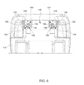
- FIG. 8 is a schematic view illustrating another embodiment of a front attachment mechanism for fastening a child carrier with a support base
- FIG. 9 is partial cross-sectional view illustrating the front attachment mechanism shown in FIG. 8 ;
- FIG. 10 is a schematic view illustrating the assembly of a latch with the support base used in the front attachment mechanism shown in FIG. 8 ;
- FIG. 11 is a schematic view illustrating the assembly of a release arm with the child carrier used in the front attachment mechanism shown in FIG. 8 .
- FIG. 1 is a perspective view illustrating one embodiment of a child safety seat assembly 100
- FIG. 2 is a schematic view illustrating a support base 104 of the child safety seat assembly 100
- the child safety seat assembly 100 can include a child carrier 102 , and a support base 104 used as a support structure.
- the child carrier 102 can include a seat shell 106 having a seat portion 108 and a seatback 110 configured to receive a child.
- the seat shell 106 including the seat portion 108 and the seatback 110 , can be formed by plastic molding.
- An underside of the seat shell 106 can include two protruding foot portions 112 , and a gap region 114 laterally delimited between the two foot portions 112 .
- Each of the foot portions 112 can respectively have an inner side surface 112 A facing the gap region 114 , and an outer side surface 112 B opposite to the inner side surface 112 A.
- the foot portions 112 can be formed at the underside of the seat portion 108 , and extend to the rear of the seatback 110 .
- the support base 104 can include a shell body 116 having an upper surface provided with two receiving areas 120 . When the child carrier 102 is installed on the upper surface of the support base 104 , the foot portions 112 can respectively rest in the receiving areas 120 .
- the child carrier 102 can be removably installed with different support structures, e.g., the support structure can be the support base 104 for installation in a vehicle, or the support structure can be a stroller frame (not shown) on which the child carrier 102 can be used as a seat structure of the stroller apparatus.
- the support structure can be the support base 104 for installation in a vehicle
- the support structure can be a stroller frame (not shown) on which the child carrier 102 can be used as a seat structure of the stroller apparatus.
- These different configurations of use can be implemented via an attachment mechanism that can be operable to fasten the child carrier 102 with either of the support base and the stroller frame. An embodiment of this attachment mechanism is described hereafter with reference to FIGS. 3-7 .
- FIG. 3 is a schematic view illustrating the construction of a front portion of the attachment mechanism for fastening the front of the child carrier 102 with the support base 104 .
- the front portion of this attachment mechanism can include the assembly of two latches 124 near a front of the child carrier 102 .
- the seat shell 106 can have an outer surface 127 facing downward, and two columns 128 transversally spaced-apart from each other can respectively project vertically outward from the outer surface 127 at a region near the front of the child carrier 102 .
- Each of the columns 128 can have an elongated shape extending downward from the outer surface 127 , and can be pivotally assembled with one latch 124 .
- each column 128 can have a hollow interior through which one corresponding latch 124 can be pivotally assembled, the pivot axis of the latch 124 being aligned with a lengthwise axis Y of the corresponding column 128 .
- each latch 124 is respectively insertable into two openings 142 formed on the upper surface 118 of the support base 104 to lock the child carrier 102 with the support base 104 .
- the two latches 124 can be similar in construction, and can be arranged at two locations transversally spaced apart from each other near the front of the child carrier 102 .
- each latch 124 can include a stem 130 extending along the axis Y, and one or two radial projections 132 (two radial projections 132 are exemplary shown in the drawings) connected with the stem 130 and extending radially outward from an outer surface of the stem 130 .
- the stem 130 can be arranged through the interior of the column 128 and project downward from the outer surface 127 , and the two radial projections 132 can be located outside the column 128 and adjacent to a distal end of the column 128 .
- Another portion of the stem 130 located inside the seat shell 106 can include a lever 134 projecting outward from the outer surface of the stem 130 .
- the two latches 124 can be respectively connected with two springs 135 .
- the springs 135 can be torsion springs.
- each spring 135 can wrap around the stem 130 of one associated latch 124 , and have an end anchored with the seat shell 106 .
- Each spring 135 can bias the corresponding latch 124 to rotate toward a locking state.
- the seat shell 106 can further include a release actuating mechanism that is operable to turn the two latches 124 to an unlocking state.
- the release actuating mechanism can include two driving members 136 respectively arranged in the interior of the two foot portions 112 .
- Each of the driving members 136 can be formed integrally as one elongated part that is movable along the interior of the foot portion 112 .
- the two driving members 136 can be respectively connected with the two latches 124 at a front end, and with a release actuator 138 at a rear end. More specifically, each driving member 136 can have a front end portion provided with a slot 140 through which the lever 134 of the corresponding latch 124 can be assembled, and a rear end portion connected with the release actuator 138 .
- the release actuator 138 can have an actuating portion exposed and accessible from an outer rear surface of the child carrier 102 for operation.
- the driving members 136 can concurrently slide relative to the seat shell 106 parallel to a longitudinal axis of the seat shell 106 , which drives the latches 124 to rotate against the biasing force of the springs 135 to the unlocking state.
- the two openings 142 are transversally spaced apart from each other, and are formed through the upper surface 118 of the shell body 116 near the front thereof.
- the two openings 142 can have a shape that can substantially mate with the shape of the columns 128 , so that the columns 128 can be inserted and fit into the openings 142 .
- the two openings 142 can be formed as cylindrical holes, and the columns 128 can be cylinders that can fit into the cylindrical holes. It is understood that the openings 142 and the columns 128 may also be formed with any other shapes.
- FIG. 4 is a schematic view illustrating an interior of the shell body 116 at a front portion thereof.
- each of the openings 142 can have a sidewall 142 A in which is formed one or more slit 144 (two slits 144 are exemplary shown in the drawings) respectively associated with the one or more radial projection 132 of the latch 124 .
- the slits 144 and the opening 142 can extend vertically, and downwardly communicate with a clearance 146 located below the upper surface 118 of the shell body 116 .
- Reinforcing plates 148 can be affixed with the shell body 116 below the upper surface 118 at two locations respectively adjacent to the openings 142 .
- Each of the reinforcing plate 148 can be cut to define a hole 150 matching with the envelop shape of the opening 142 provided with the slits 144 .
- a region of the support base 104 adjacently surrounding the upper rim of each opening 142 can further include one or more ramp surface 152 respectively associated with the one or more slit 144 .
- Each ramp surface 152 can be formed as a sloped surface that extends downward and is adjacent to one corresponding slit 144 .
- FIGS. 5 and 6 are schematic view illustrating exemplary operation of the latches 124 for locking the child carrier 102 with the support base 104 .
- the child carrier 102 When the child carrier 102 is installed on the support base 104 , the child carrier 102 can be placed such that the columns 128 are respectively aligned with the openings 142 and the radial projections 132 respectively contact with the ramp surfaces 152 . While they are in contact with the ramp surfaces 152 , the radial projections 132 are respectively misaligned with respect to the slits 144 . The child carrier 102 then can be lowered toward the support base 104 .
- the respective sliding contact between the radial projections 132 and the ramp surfaces 152 can cause the latches 124 to self rotate against the biasing force of the springs 135 toward the corresponding slits 144 .
- the downward movement of the child carrier 102 thus can drive rotation the latches 124 toward the unlocking state.
- the radial projections 132 respectively align and engage with the slits 144 (as shown in FIG. 5 )
- the latches 124 are in the unlocking state.
- the columns 128 and the latches 124 then can fully travel downward through the openings 142 and the slits 144 . While the columns 128 travel downward, the engagement of the radial projections 132 in the slits 144 can prevent unlocking rotation of the latches 124 .
- each latch 124 When the columns 128 are fully inserted, the radial projections 132 of each latch 124 respectively disengage from the slits 144 and enter the clearance 146 below the reinforcing plate 148 .
- the biasing force applied by each spring 135 then can urge rotation of the corresponding latch 124 to the locking state, which causes the radial projections 132 to misalign with respect to the slits 144 (as shown in FIG. 6 ).
- the abutment of the radial projections 132 against the reinforcement plate 148 can prevent upward removal of the child carrier 102 from the support base 104 .
- the engagement of the columns 128 in the openings 142 can prevent horizontal displacement of the child carrier 102 relative to the support base 104 .
- the release actuator 138 can be pulled to cause rearward displacement of the driving members 136 .
- the rearward displacement of the driving members 136 can drive the latches 124 in rotation about the respective axes Y to the unlocking state.
- FIG. 7 is a schematic view illustrating a rear portion of the attachment mechanism for attaching a rear of the child seat 102 with the support base 104 .
- the rear portion of the attachment mechanism can include the assembly of two latching units 126 toward a rear of the child carrier 102 .
- the two latching units 126 can be respectively assembled in the foot portions 112 of the seat shell 106 , and have a similar construction.
- Each of the latching units 126 can include two latches 154 and 156 that are assembled through the interior of the corresponding foot portion 112 , and are movable transversally relative to the seat shell 106 in opposite directions.
- the latch 154 can protrude outward through an opening on an inner surface 112 A of the foot portion 112 that faces a central region of the seat shell 106
- the latch 156 can protrude outward through an opening on an outer surface 112 B of the foot portion 112 facing an outside of the seat shell 106
- the latches 154 and 156 can have respective sleeve portions 154 A and 156 A that are telescopically assembled with each other inside the foot portion 112 .
- the respective outer surfaces of the sleeve portions 154 A and 156 A can respectively include protruding ribs 154 B and 156 B.
- a spring 158 (shown with phantom lines) having two ends respectively connected with the latches 154 and 156 can be assembled in the interior of the sleeve portions 154 A and 156 A.
- the spring 158 can bias the latches 154 and 156 to the locking state, so that the engaging ends 154 C and 156 C thereof respectively project outward from the inner and outer surface 112 A and 112 B of the foot portion 112 .
- the ribs 154 B and 156 B can be in sliding contact with two slanted surfaces 160 A and 160 B provided in one driving member 136 extending along the foot portion 112 .
- the engaging end 154 C of the latch 154 can engage with an opening 159 (as better shown in FIG. 2 ) on the support base 104 for locking the child carrier 102 with the support base 104 .
- the engaging end 156 C of the latch 156 can engage with the stroller frame for locking the child carrier 102 in place.
- the release actuator 138 (better shown in FIG. 1 ) can be pulled to cause rearward displacement of the driving members 136 .
- the rearward displacement of the driving members 136 can concurrently drive the latches 154 and 156 of each latching unit 126 to slide transversally toward the interior of the foot portion 112 to disengage from the support base 104 or stroller frame.
- the child carrier 102 and the support base 104 can be fastened with each other via four attachment points comprised of the two latches 124 near the front and the two latching units 126 near the rear.
- the latching units 126 at the rear can also integrate the latches 156 used for installing the child carrier 102 on a stroller frame.
- the latches 124 provided at the front of the child carrier 102 may also lock with a stroller having a structure like the support base 104 described previously.
- the stroller may include a structure having the openings 142 , slits 144 , clearance 146 , reinforcement plates 148 and ramp surfaces 152 , which may interact with the latches 124 as previously described to lock the child carrier 102 with the stroller.
- the child safety seat assemblies described herein can also use the latches 124 to lock the child carrier 102 with different support structures such as the support base 104 or a stroller.
- certain embodiments may also implement the latches 124 at the front of the child carrier 102 without the latching units 126 at the rear of the child carrier 102 .
- the latches 124 at the front of the child carrier 102 may be implemented in combination with other constructions of the latching units at the rear of the child carrier 102 .
- FIG. 8-11 are schematic views illustrating another embodiment that uses two fastening assemblies 220 in replacement of the latches 124 previously described for attaching the front of the child carrier 102 with the support base 104 .
- the two fastening assemblies 220 are similar in construction, and can be configured to respectively attach the two front ends of the foot portions 112 in the two receiving areas 120 of the support base 104 .
- Each of the fastening assemblies 220 can include a latch 222 connected with the shell body 116 of the support base 104 , and a release arm 224 assembled with the seat shell 106 near the front of the child carrier 102 .
- the latch 222 can be operable to engage with the child carrier 102 for locking the child carrier 102 in place.
- the release arm 224 can be operable to urge displacement of the latch 222 from the locking state to the unlocking state for allowing removal of the child carrier 102 from the support base 104 .
- FIG. 10 is a schematic view illustrating the assembly of the latch 222 with the shell body 116 .
- the latch 222 can be arranged adjacent to one receiving area 120 associated therewith.
- the latch 222 can be pivotally assembled with a mount frame 226 that is affixed with the shell body 116 of the support base 104 .
- the mount frame 226 can be formed as steel plate having a slotted portion 228 opened upward that is exposed outward in the receiving area 120 of the shell body 116 .
- the receiving area 120 can include a support surface 120 A on which the foot portion 112 can rest when the child carrier 102 is installed on the support base 104 , and an upright surface 120 B that raises upward from the support surface 120 A can define an end of the receiving area 120 along a lengthwise direction thereof.
- the mount frame 226 and the latch 222 can be arranged adjacent to the upright surface 120 B.
- the latch 222 can pivot relative to shell body 116 between a locking state in which the latch 222 projects outward through the upright surface 120 B and upwardly closes the slotted portion 228 , and an unlocking state in which the latch 222 retracts toward the interior of the shell body 116 and upwardly opens the slotted portion 228 .
- a spring 230 can have two ends respectively connected with the mount frame 226 and the latch 222 . The spring 230 can bias the latch 222 toward the locking state for closing the slotted portion 228 of the mount frame 226 .
- FIG. 11 is a schematic view illustrating the assembly of the release arm 224 with the seat shell 106 .
- the release arm 224 can be pivotally connected with a bracket 232 that is affixed with the seat shell 106 in the interior of the foot portion 112 .
- the release arm 224 can have a U-shape including two side segments 224 A and a middle segment 224 B connected between the two side segments 224 A.
- the release arm 224 can further include a bent extension 224 C that extends downward.
- the bent extension 224 C of the release arm 224 can be pivotally connected with a front portion of the driving member 136 that is arranged in the foot portion 112 .
- the driving member 136 can have a rear end that is connected with the release actuator 138 (such as exemplary shown in FIG. 1 ) accessible from a rear of the child carrier 102 for operation.
- the release arm 224 including the segments 224 A and 224 B and the bent extension 224 C, can be formed as one integral piece.
- the bracket 232 can be affixed with a rod 234 that is disposed spaced apart from the pivot axis of the release arm 224 , and extends transversally across an opening 236 formed the foot portion 112 .
- the foot portion 112 can include a bottom surface 238 and a front upright surface 240 raising upward from the bottom surface 238 , and the opening 236 can be cut through the bottom surface 238 and the front upright surface 240 .
- the release arm 224 can rotate toward and away from the rod 234 . More specifically, a rearward displacement of the driving member 136 toward the rear of the child carrier 102 can drive the release arm 224 to rotate toward the rod 234 , and a spring 242 may be provided to bias the release arm 224 to rotate away from the rod 234 .
- the spring 242 may exemplary have two ends respectively connected with a flange 244 formed on the driving member 136 and a rib 246 provided in the foot portion 112 of the seat shell 106 . When no pulling force is applied on the release actuator 138 , the spring 242 can thereby bias the driving member 136 forward so as to cause the release arm 224 to rotate to an initial position away from the rod 234 .
- each fastening assembly 220 Exemplary operation of each fastening assembly 220 is described hereafter with reference to FIGS. 8-11 .
- the child carrier 102 For installing the child carrier 102 on the support base 104 , the child carrier 102 can be placed such that the foot portions 112 are respectively received in the receiving areas 120 of the support base 104 and the front upright surfaces 240 of the foot portions 112 respectively lie adjacent to the upright surfaces 120 B.
- the slotted portion 228 of each mount frame 226 can partially travel through the opening 236 of the corresponding foot portion 112 , and the rod 234 can be received in the slotted portion 228 .
- the spring 230 can urge the latch 222 to the locking state: the latch 222 can thereby travel through the opening 236 on the front upright surface 240 into the interior of the foot portion 112 to upwardly close the slotted portion 228 and engage with the rod 234 . Accordingly, the latch 222 can restrainedly keep the rod 234 in the slotted portion 228 and block upward removal of the child carrier 102 from the support base 104 .
- the release arm 224 is kept in its initial position away from the rod 234 owing to the biasing action by the spring 242 . Accordingly, the release arm 224 does not interfere with the engagement of the latch 222 over the rod 234 .
- the release actuator 138 (such as exemplary shown in FIG. 1 ) can be pulled to cause rearward displacement of the driving members 136 .
- the rearward displacement of each driving member 136 can respectively drive rotation of the release arm 224 toward the rod 234 that is received in the slotted portion 228 .
- the release arm 224 (in particular the middle segment 224 B thereof) can push the latch 222 to move against the biasing force of the spring 230 .
- the latch 222 Being urged in displacement by the release arm 224 , the latch 222 can rotate from the locking state to the unlocking state for disengaging from the rod 234 .
- the release arm 224 can straddle the slotted portion 228 .
- the child carrier 102 can be lifted from the support base 104 , which removes the rod 234 from the slotted portion 228 .
- the attachment points can include two front latches having a same construction, and two rear latching units having a construction different from the front latches.
- the four latches can be conveniently driven to release via two driving members connected with a release actuator accessible from a rear of the child carrier.
Landscapes
- Engineering & Computer Science (AREA)
- Health & Medical Sciences (AREA)
- Child & Adolescent Psychology (AREA)
- General Health & Medical Sciences (AREA)
- Aviation & Aerospace Engineering (AREA)
- Transportation (AREA)
- Mechanical Engineering (AREA)
- Seats For Vehicles (AREA)
Priority Applications (2)
| Application Number | Priority Date | Filing Date | Title |
|---|---|---|---|
| US14/195,927 US9469222B2 (en) | 2013-03-05 | 2014-03-04 | Child safety seat assembly |
| US15/265,248 US10245980B2 (en) | 2013-03-05 | 2016-09-14 | Child safety seat assembly |
Applications Claiming Priority (2)
| Application Number | Priority Date | Filing Date | Title |
|---|---|---|---|
| US201361851296P | 2013-03-05 | 2013-03-05 | |
| US14/195,927 US9469222B2 (en) | 2013-03-05 | 2014-03-04 | Child safety seat assembly |
Related Child Applications (1)
| Application Number | Title | Priority Date | Filing Date |
|---|---|---|---|
| US15/265,248 Division US10245980B2 (en) | 2013-03-05 | 2016-09-14 | Child safety seat assembly |
Publications (2)
| Publication Number | Publication Date |
|---|---|
| US20140252829A1 US20140252829A1 (en) | 2014-09-11 |
| US9469222B2 true US9469222B2 (en) | 2016-10-18 |
Family
ID=50193340
Family Applications (2)
| Application Number | Title | Priority Date | Filing Date |
|---|---|---|---|
| US14/195,927 Active 2034-04-30 US9469222B2 (en) | 2013-03-05 | 2014-03-04 | Child safety seat assembly |
| US15/265,248 Active 2034-12-16 US10245980B2 (en) | 2013-03-05 | 2016-09-14 | Child safety seat assembly |
Family Applications After (1)
| Application Number | Title | Priority Date | Filing Date |
|---|---|---|---|
| US15/265,248 Active 2034-12-16 US10245980B2 (en) | 2013-03-05 | 2016-09-14 | Child safety seat assembly |
Country Status (4)
| Country | Link |
|---|---|
| US (2) | US9469222B2 (pl) |
| EP (1) | EP2774804B1 (pl) |
| CN (2) | CN104029615B (pl) |
| PL (1) | PL2774804T3 (pl) |
Cited By (13)
| Publication number | Priority date | Publication date | Assignee | Title |
|---|---|---|---|---|
| US20150359354A1 (en) * | 2014-06-12 | 2015-12-17 | Artsana Usa, Inc. | Multi-mode high chair |
| US11034266B2 (en) | 2019-02-27 | 2021-06-15 | Dorel Juvenile Group, Inc. | Child restraint |
| US20240239398A1 (en) * | 2023-01-18 | 2024-07-18 | Evenflo Company, Inc. | Infant transport system and base with removable wheel guards |
| US12371089B2 (en) | 2023-01-20 | 2025-07-29 | Evenflo Company, Inc. | Infant transport system and assembly with caster alignment |
| US12397689B2 (en) | 2023-01-18 | 2025-08-26 | Evenflo Company, Inc. | Infant transport system and assembly |
| US12427896B2 (en) | 2022-10-07 | 2025-09-30 | Dorel Juvenile Group, Inc. | Child restraint |
| US12539906B2 (en) | 2023-01-20 | 2026-02-03 | Evenflo Company, Inc. | Infant transport system and assembly |
| US12539907B2 (en) | 2023-01-20 | 2026-02-03 | Evenflo Company, Inc. | Infant transport system and assembly |
| US12545312B2 (en) | 2023-01-18 | 2026-02-10 | Evenflo Company, Inc. | Infant transport system and assembly |
| US12545153B2 (en) | 2023-01-18 | 2026-02-10 | Evenflo Company, Inc. | Infant transport system and base with anti-rebound panel level indicator |
| US12565254B2 (en) | 2023-01-20 | 2026-03-03 | Evenflo Company, Inc. | Infant transport system and assembly |
| US12570190B2 (en) | 2023-01-20 | 2026-03-10 | Evenflo Company, Inc. | Infant transport system and assembly |
| US12570188B2 (en) | 2022-10-06 | 2026-03-10 | Dorel Juvenile Group, Inc. | Child restraint |
Families Citing this family (7)
| Publication number | Priority date | Publication date | Assignee | Title |
|---|---|---|---|---|
| US9185099B2 (en) * | 2013-09-23 | 2015-11-10 | Airwatch Llc | Securely authorizing access to remote resources |
| CN203543730U (zh) * | 2013-10-21 | 2014-04-16 | 中山市隆成日用制品有限公司 | 婴童安全座椅与基座扣合释放机构 |
| US9676304B2 (en) | 2014-11-25 | 2017-06-13 | Ford Global Technologies, Llc | Vehicle seat with ramp for facilitating ISO fix child seat installation |
| US10427559B2 (en) * | 2016-10-07 | 2019-10-01 | Dorel Juvenile Group, Inc. | Child restraint system with seat-orientation adjuster |
| CA2997481C (en) * | 2017-03-03 | 2019-05-07 | Wonderland Switzerland Ag | Support base for a child safety seat |
| CN113815501B (zh) * | 2020-06-19 | 2024-06-04 | 宝钜瑞士股份有限公司 | 儿童安全座椅及其顶杆调整机构 |
| CN113815503B (zh) * | 2020-06-19 | 2024-08-02 | 宝钜瑞士股份有限公司 | 儿童安全座椅及其座椅固定装置 |
Citations (10)
| Publication number | Priority date | Publication date | Assignee | Title |
|---|---|---|---|---|
| US5461808A (en) * | 1993-02-08 | 1995-10-31 | Fritts; Robert W. | Table top backlit display |
| CN1210701A (zh) | 1997-09-10 | 1999-03-17 | 哥瑞考儿童产品公司 | 婴儿承载架的安装系统 |
| CN1365906A (zh) | 2000-11-24 | 2002-08-28 | 宫比株式会社 | 一种儿童汽车座椅和婴儿车 |
| US20040054939A1 (en) * | 2002-09-03 | 2004-03-18 | Aloke Guha | Method and apparatus for power-efficient high-capacity scalable storage system |
| CN101096189A (zh) | 2006-06-30 | 2008-01-02 | 米克研究和开发有限公司 | 活动式儿童汽车座椅 |
| CN201124778Y (zh) | 2007-12-06 | 2008-10-01 | 宁波均胜工业有限公司 | 儿童汽车安全座椅 |
| EP2272709A2 (en) | 2009-07-05 | 2011-01-12 | Graco Children's Products, Inc. | Car seat installation and recline mechanism |
| US20120326474A1 (en) | 2011-06-27 | 2012-12-27 | Wonderland Nurserygoods Company Limited | Child Safety Seat |
| US8388063B2 (en) * | 2009-03-25 | 2013-03-05 | Wonderland Nurserygoods Company Limited | Child booster seat and height-adjustment mechanism thereof |
| US8955909B2 (en) * | 2011-12-30 | 2015-02-17 | Kawasaki Jukogyo Kabushiki Kaisha | Vehicle |
Family Cites Families (5)
| Publication number | Priority date | Publication date | Assignee | Title |
|---|---|---|---|---|
| US5567008A (en) * | 1994-11-04 | 1996-10-22 | Cosco, Inc. | Portable infant seat having a detachable base |
| FR2727908A1 (fr) * | 1994-12-08 | 1996-06-14 | Allegre Puericulture Hygiene S | Siege transat notamment pour enfants en bas age |
| JP2006151299A (ja) * | 2004-11-30 | 2006-06-15 | Car Mate Mfg Co Ltd | チャイルドシート |
| AU2010241533B2 (en) * | 2009-11-19 | 2016-11-17 | Hbg Ip Holding Pty Ltd | Swing Base for a Child Restraint |
| CN103622374B (zh) | 2012-08-27 | 2016-08-03 | 明门香港股份有限公司 | 座椅快拆机构及具有该座椅快拆机构的儿童座椅 |
-
2014
- 2014-03-04 PL PL14157642T patent/PL2774804T3/pl unknown
- 2014-03-04 EP EP14157642.1A patent/EP2774804B1/en active Active
- 2014-03-04 CN CN201410075782.5A patent/CN104029615B/zh active Active
- 2014-03-04 US US14/195,927 patent/US9469222B2/en active Active
- 2014-03-04 CN CN201610320461.6A patent/CN105818719B/zh active Active
-
2016
- 2016-09-14 US US15/265,248 patent/US10245980B2/en active Active
Patent Citations (11)
| Publication number | Priority date | Publication date | Assignee | Title |
|---|---|---|---|---|
| US5461808A (en) * | 1993-02-08 | 1995-10-31 | Fritts; Robert W. | Table top backlit display |
| CN1210701A (zh) | 1997-09-10 | 1999-03-17 | 哥瑞考儿童产品公司 | 婴儿承载架的安装系统 |
| US6070890A (en) | 1997-09-10 | 2000-06-06 | Graco Children's Products Inc. | Infant carrier mounting system |
| CN1365906A (zh) | 2000-11-24 | 2002-08-28 | 宫比株式会社 | 一种儿童汽车座椅和婴儿车 |
| US20040054939A1 (en) * | 2002-09-03 | 2004-03-18 | Aloke Guha | Method and apparatus for power-efficient high-capacity scalable storage system |
| CN101096189A (zh) | 2006-06-30 | 2008-01-02 | 米克研究和开发有限公司 | 活动式儿童汽车座椅 |
| CN201124778Y (zh) | 2007-12-06 | 2008-10-01 | 宁波均胜工业有限公司 | 儿童汽车安全座椅 |
| US8388063B2 (en) * | 2009-03-25 | 2013-03-05 | Wonderland Nurserygoods Company Limited | Child booster seat and height-adjustment mechanism thereof |
| EP2272709A2 (en) | 2009-07-05 | 2011-01-12 | Graco Children's Products, Inc. | Car seat installation and recline mechanism |
| US20120326474A1 (en) | 2011-06-27 | 2012-12-27 | Wonderland Nurserygoods Company Limited | Child Safety Seat |
| US8955909B2 (en) * | 2011-12-30 | 2015-02-17 | Kawasaki Jukogyo Kabushiki Kaisha | Vehicle |
Non-Patent Citations (2)
| Title |
|---|
| Office Action in co-pending Chinese Patent Application No. 201410075782.5 dated Nov. 24, 2015 (see p. 5). |
| Office Action in co-pending Chinese Patent Application No. 201410075782.5 dated Nov. 24, 2015. |
Cited By (15)
| Publication number | Priority date | Publication date | Assignee | Title |
|---|---|---|---|---|
| US9635955B2 (en) * | 2014-06-12 | 2017-05-02 | Artsana Usa, Inc. | Multi-mode high chair |
| US20150359354A1 (en) * | 2014-06-12 | 2015-12-17 | Artsana Usa, Inc. | Multi-mode high chair |
| US11034266B2 (en) | 2019-02-27 | 2021-06-15 | Dorel Juvenile Group, Inc. | Child restraint |
| US12570188B2 (en) | 2022-10-06 | 2026-03-10 | Dorel Juvenile Group, Inc. | Child restraint |
| US12427896B2 (en) | 2022-10-07 | 2025-09-30 | Dorel Juvenile Group, Inc. | Child restraint |
| US20240239398A1 (en) * | 2023-01-18 | 2024-07-18 | Evenflo Company, Inc. | Infant transport system and base with removable wheel guards |
| US12397689B2 (en) | 2023-01-18 | 2025-08-26 | Evenflo Company, Inc. | Infant transport system and assembly |
| US12459555B2 (en) * | 2023-01-18 | 2025-11-04 | Evenflo Company, Inc. | Infant transport system and base with removable wheel guards |
| US12545312B2 (en) | 2023-01-18 | 2026-02-10 | Evenflo Company, Inc. | Infant transport system and assembly |
| US12545153B2 (en) | 2023-01-18 | 2026-02-10 | Evenflo Company, Inc. | Infant transport system and base with anti-rebound panel level indicator |
| US12539906B2 (en) | 2023-01-20 | 2026-02-03 | Evenflo Company, Inc. | Infant transport system and assembly |
| US12539907B2 (en) | 2023-01-20 | 2026-02-03 | Evenflo Company, Inc. | Infant transport system and assembly |
| US12565254B2 (en) | 2023-01-20 | 2026-03-03 | Evenflo Company, Inc. | Infant transport system and assembly |
| US12570190B2 (en) | 2023-01-20 | 2026-03-10 | Evenflo Company, Inc. | Infant transport system and assembly |
| US12371089B2 (en) | 2023-01-20 | 2025-07-29 | Evenflo Company, Inc. | Infant transport system and assembly with caster alignment |
Also Published As
| Publication number | Publication date |
|---|---|
| PL2774804T3 (pl) | 2018-10-31 |
| CN104029615A (zh) | 2014-09-10 |
| US20140252829A1 (en) | 2014-09-11 |
| CN105818719B (zh) | 2019-06-21 |
| EP2774804A1 (en) | 2014-09-10 |
| US10245980B2 (en) | 2019-04-02 |
| CN105818719A (zh) | 2016-08-03 |
| CN104029615B (zh) | 2016-06-29 |
| US20170001544A1 (en) | 2017-01-05 |
| EP2774804B1 (en) | 2018-05-02 |
Similar Documents
| Publication | Publication Date | Title |
|---|---|---|
| US9469222B2 (en) | Child safety seat assembly | |
| US8882196B2 (en) | Child safety seat | |
| AU2023204131B2 (en) | Child seat with belt tensioning mechanism for improved installation | |
| US20120326474A1 (en) | Child Safety Seat | |
| US10023079B2 (en) | Child safety seat | |
| GB2553622B (en) | Child saftey seat | |
| EP2703210B1 (en) | Child seat with belt tensioning mechanism for improved installation | |
| US8998317B2 (en) | Support base for a child safety seat | |
| US9085250B2 (en) | Base for child safety carrier | |
| US9789791B2 (en) | Child safety seat | |
| CN104057852B (zh) | 用于儿童安全座椅的固定装置 | |
| GB2482061A (en) | Child safety seat assembly | |
| CA2763903A1 (en) | Child safety seat assembly | |
| JP2010076758A (ja) | チャイルドシート‐isofix | |
| US10442324B2 (en) | Child safety seat | |
| US8714650B2 (en) | Seat assembly having a moveable head restraint assembly | |
| US10377286B2 (en) | Folding head restraint mechanism | |
| KR101671644B1 (ko) | 시트 레일의 록킹 장치 | |
| GB2488672A (en) | Anchor attachment structure for child safety seat | |
| US11413991B2 (en) | Child safety seat | |
| JP2025532405A (ja) | チャイルド・シート用の繋止システム | |
| CA2763906C (en) | Child safety seat | |
| CN114683976A (zh) | 儿童安全座椅 | |
| JP2010184528A (ja) | 車両のシートスライド装置 |
Legal Events
| Date | Code | Title | Description |
|---|---|---|---|
| AS | Assignment |
Owner name: WONDERLAND NURSERYGOODS COMPANY LIMITED, HONG KONG Free format text: ASSIGNMENT OF ASSIGNORS INTEREST;ASSIGNOR:WILLIAMS, BRUCE L.;REEL/FRAME:032341/0844 Effective date: 20140220 |
|
| STCF | Information on status: patent grant |
Free format text: PATENTED CASE |
|
| AS | Assignment |
Owner name: WONDERLAND SWITZERLAND AG, SWITZERLAND Free format text: ASSIGNMENT OF ASSIGNORS INTEREST;ASSIGNOR:WONDERLAND NURSERYGOODS COMPANY LIMITED;REEL/FRAME:045898/0367 Effective date: 20180220 |
|
| MAFP | Maintenance fee payment |
Free format text: PAYMENT OF MAINTENANCE FEE, 4TH YEAR, LARGE ENTITY (ORIGINAL EVENT CODE: M1551); ENTITY STATUS OF PATENT OWNER: LARGE ENTITY Year of fee payment: 4 |
|
| MAFP | Maintenance fee payment |
Free format text: PAYMENT OF MAINTENANCE FEE, 8TH YEAR, LARGE ENTITY (ORIGINAL EVENT CODE: M1552); ENTITY STATUS OF PATENT OWNER: LARGE ENTITY Year of fee payment: 8 |