US9450543B2 - Bandwidth-extended Doherty power amplifier - Google Patents
Bandwidth-extended Doherty power amplifier Download PDFInfo
- Publication number
- US9450543B2 US9450543B2 US14/367,098 US201214367098A US9450543B2 US 9450543 B2 US9450543 B2 US 9450543B2 US 201214367098 A US201214367098 A US 201214367098A US 9450543 B2 US9450543 B2 US 9450543B2
- Authority
- US
- United States
- Prior art keywords
- amplifier
- wavelength line
- dpa
- impedance
- bandwidth
- Prior art date
- Legal status (The legal status is an assumption and is not a legal conclusion. Google has not performed a legal analysis and makes no representation as to the accuracy of the status listed.)
- Active
Links
Images


Classifications
-
- H—ELECTRICITY
- H03—ELECTRONIC CIRCUITRY
- H03F—AMPLIFIERS
- H03F1/00—Details of amplifiers with only discharge tubes, only semiconductor devices or only unspecified devices as amplifying elements
- H03F1/02—Modifications of amplifiers to raise the efficiency, e.g. gliding Class A stages, use of an auxiliary oscillation
- H03F1/04—Modifications of amplifiers to raise the efficiency, e.g. gliding Class A stages, use of an auxiliary oscillation in discharge-tube amplifiers
- H03F1/06—Modifications of amplifiers to raise the efficiency, e.g. gliding Class A stages, use of an auxiliary oscillation in discharge-tube amplifiers to raise the efficiency of amplifying modulated radio frequency waves; to raise the efficiency of amplifiers acting also as modulators
- H03F1/07—Doherty-type amplifiers
-
- H—ELECTRICITY
- H03—ELECTRONIC CIRCUITRY
- H03F—AMPLIFIERS
- H03F3/00—Amplifiers with only discharge tubes or only semiconductor devices as amplifying elements
- H03F3/189—High frequency amplifiers, e.g. radio frequency amplifiers
- H03F3/19—High frequency amplifiers, e.g. radio frequency amplifiers with semiconductor devices only
-
- H—ELECTRICITY
- H03—ELECTRONIC CIRCUITRY
- H03F—AMPLIFIERS
- H03F1/00—Details of amplifiers with only discharge tubes, only semiconductor devices or only unspecified devices as amplifying elements
- H03F1/02—Modifications of amplifiers to raise the efficiency, e.g. gliding Class A stages, use of an auxiliary oscillation
- H03F1/0205—Modifications of amplifiers to raise the efficiency, e.g. gliding Class A stages, use of an auxiliary oscillation in transistor amplifiers
- H03F1/0288—Modifications of amplifiers to raise the efficiency, e.g. gliding Class A stages, use of an auxiliary oscillation in transistor amplifiers using a main and one or several auxiliary peaking amplifiers whereby the load is connected to the main amplifier using an impedance inverter, e.g. Doherty amplifiers
-
- H—ELECTRICITY
- H03—ELECTRONIC CIRCUITRY
- H03F—AMPLIFIERS
- H03F1/00—Details of amplifiers with only discharge tubes, only semiconductor devices or only unspecified devices as amplifying elements
- H03F1/42—Modifications of amplifiers to extend the bandwidth
-
- H—ELECTRICITY
- H03—ELECTRONIC CIRCUITRY
- H03F—AMPLIFIERS
- H03F1/00—Details of amplifiers with only discharge tubes, only semiconductor devices or only unspecified devices as amplifying elements
- H03F1/42—Modifications of amplifiers to extend the bandwidth
- H03F1/48—Modifications of amplifiers to extend the bandwidth of aperiodic amplifiers
-
- H—ELECTRICITY
- H03—ELECTRONIC CIRCUITRY
- H03F—AMPLIFIERS
- H03F3/00—Amplifiers with only discharge tubes or only semiconductor devices as amplifying elements
- H03F3/20—Power amplifiers, e.g. Class B amplifiers, Class C amplifiers
- H03F3/21—Power amplifiers, e.g. Class B amplifiers, Class C amplifiers with semiconductor devices only
- H03F3/211—Power amplifiers, e.g. Class B amplifiers, Class C amplifiers with semiconductor devices only using a combination of several amplifiers
-
- H—ELECTRICITY
- H03—ELECTRONIC CIRCUITRY
- H03F—AMPLIFIERS
- H03F2200/00—Indexing scheme relating to amplifiers
- H03F2200/36—Indexing scheme relating to amplifiers the amplifier comprising means for increasing the bandwidth
-
- H—ELECTRICITY
- H03—ELECTRONIC CIRCUITRY
- H03F—AMPLIFIERS
- H03F2203/00—Indexing scheme relating to amplifiers with only discharge tubes or only semiconductor devices as amplifying elements covered by H03F3/00
- H03F2203/20—Indexing scheme relating to power amplifiers, e.g. Class B amplifiers, Class C amplifiers
- H03F2203/21—Indexing scheme relating to power amplifiers, e.g. Class B amplifiers, Class C amplifiers with semiconductor devices only
- H03F2203/211—Indexing scheme relating to power amplifiers, e.g. Class B amplifiers, Class C amplifiers with semiconductor devices only using a combination of several amplifiers
- H03F2203/21106—An input signal being distributed in parallel over the inputs of a plurality of power amplifiers
-
- H—ELECTRICITY
- H03—ELECTRONIC CIRCUITRY
- H03F—AMPLIFIERS
- H03F2203/00—Indexing scheme relating to amplifiers with only discharge tubes or only semiconductor devices as amplifying elements covered by H03F3/00
- H03F2203/20—Indexing scheme relating to power amplifiers, e.g. Class B amplifiers, Class C amplifiers
- H03F2203/21—Indexing scheme relating to power amplifiers, e.g. Class B amplifiers, Class C amplifiers with semiconductor devices only
- H03F2203/211—Indexing scheme relating to power amplifiers, e.g. Class B amplifiers, Class C amplifiers with semiconductor devices only using a combination of several amplifiers
- H03F2203/21139—An impedance adaptation circuit being added at the output of a power amplifier stage
-
- H—ELECTRICITY
- H03—ELECTRONIC CIRCUITRY
- H03F—AMPLIFIERS
- H03F3/00—Amplifiers with only discharge tubes or only semiconductor devices as amplifying elements
- H03F3/68—Combinations of amplifiers, e.g. multi-channel amplifiers for stereophonics
Definitions
- the present invention relates to a power amplifier, and more specifically, to a bandwidth-extended Doherty power amplifier.
- the efficient Doherty power amplifier DPA has become increasingly popular in communication systems.
- the DPA has defective properties such as very narrow bandwidth and large size.
- the DPA narrow-band property is mainly due to the narrow-band property of a narrow-band mixer.
- An output mixer generally has a higher Q point, while the higher Q point causes a narrower bandwidth.
- the Q point may amount to 0.76.
- the large-size property is due to the fact that the DPA output mixer uses two 1 ⁇ 4 wavelength lines ( ⁇ /4).
- the length of the 1 ⁇ 4 wavelength line is about 47 mm; therefore, the size design cannot be scaled down.
- FIG. 1 a scheme for extending bandwidth for a DPA has been proposed, as shown in FIG. 1 .
- a 1 ⁇ 4 wavelength line 101 of 35.3 Ohm is grounded to form a minor with the 1 ⁇ 4 wavelength line of the Doherty mixer on a layout.
- the peaking amplifier is closed, and the carrier amplifier will work in a high-resistance state (generally at 100 Ohm).
- resistance dispersion will become more converged than that of a common DPA with the carrier amplifier working at the high-impedance. Therefore, the bandwidth of a bandwidth-extended DPA will be much wider than that of a non-bandwidth extended DPA, as shown in FIG. 2 .
- the present invention provides a new structure of a Doherty power amplifier so as to lower Q point and reduce use of 1 ⁇ 4 wavelength lines.
- the present method extends the DPA bandwidth with a simpler and more convenient design and facilitates the design of a narrowed size.
- a Doherty power amplifier comprising an input power divider into which an input signal of the Doherty power amplifier is inputted, one output of the input power divider being connected to a carrier amplifier, the other output of the divider being connected to a first 1 ⁇ 4 wavelength line, the other end of the first 1 ⁇ 4 wavelength line being connected to a peaking amplifier, one end of the carrier amplifier being connected to a second 1 ⁇ 4 wavelength line, the other end of the second 1 ⁇ 4 wavelength line being connected to the peaking amplifier; a junction point between the second 1 ⁇ 4 wavelength line and the peaking amplifier being a signal output point of the Doherty power amplifier.
- the load impedance Z 02 of the peaking amplifier is determined by the following equation:
- Z 02 50 * ( 1 + ⁇ ) ⁇ , where ⁇ is power ratio.
- FIGS. 1 a and 1 b show a principle diagram and a layout diagram of an existing bandwidth-extended DPA, respectively.
- FIGS. 2 a and 2 b show an impedance dispersion property and bandwidth of an existing bandwidth-extended DPA, respectively.
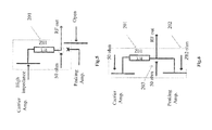
- FIGS. 3 a and 3 b show a principle diagram and a layout diagram of a bandwidth-extended DPA according to an embodiment of the present invention, respectively.
- FIGS. 4 a and 4 b show an impedance dispersion property and bandwidth of a bandwidth-extended DPA according to an embodiment of the present invention, respectively.
- FIG. 5 shows an equivalent circuit diagram of a bandwidth-extended DPA according to an embodiment of the present invention when it works at a small signal input.
- FIG. 6 shows an equivalent circuit diagram of a bandwidth-extended DPA according to an embodiment of the present invention when it works at a large signal input.
- FIG. 7 shows performance comparison between the traditional scheme and the present solution employed in a balance-type DPA using MD7IC2755NR1.
- FIG. 8 shows performance comparison between the traditional scheme and the present solution employed in a non-balance type DPA using MRF8S21120HR3 and MRF8S21201HR3.
- a bandwidth-extended Doherty power amplifier comprises an input power divider into which an input signal of the Doherty power amplifier is inputted, one output of the input power divider being connected to a carrier amplifier, the other output of the divider being connected to a first 1 ⁇ 4 wavelength line, the other end of the first 1 ⁇ 4 wavelength line being connected to a peaking amplifier, one end of the carrier amplifier being connected to a second 1 ⁇ 4 wavelength line, the other end of the second 1 ⁇ 4 wavelength line being connected to the peaking amplifier, a junction point between the second 1 ⁇ 4 wavelength line and the peaking amplifier being a signal output point of the Doherty power amplifier.
- the characteristic impedance Z 01 of the second 1 ⁇ 4 wavelength line 201 and the load impedance Z 02 of the peaking amplifier 202 have to be determined.
- the load impedance Z 02 of the peaking amplifier 202 is determined by the following equation:
- the carrier amplifier works at a high impedance state, as shown in FIG. 5 a.
- the load impedance Z high _ impedance of the carrier amplifier is 100 Ohm, while for a non-balance type DPA with a power ratio 1:2, the load impedance Z high _ impedance of the carrier amplifier is 150 Ohm.
- the load impedance of the carrier amplifier is 50 Ohm.
- the impedance through the second 1 ⁇ 4 wavelength line 201 is converted into 50*(1+ ⁇ ) Ohm, and is connected in parallel with the load impedance Z 02 of the peaking amplifier, i.e., 50 Ohm, as shown in FIG. 6 .
- the load impedance of the carrier amplifier is reduced to 50 Ohm, and the load impedance of the peaking amplifier is reduced to Z 02 .
- This design of the present invention modifies the characteristic impedance of the peaking amplifier 202 and the characteristic impedance of the second 1 ⁇ 4 wavelength line, such that the impedance of the DPA mixer is maintained at 50 Ohm. Because the impedance of the mixer rises to 50 Ohm, when the input signal is relatively small and the peaking amplifier does not work, the impedance of the second 1 ⁇ 4 wavelength line 201 is converted from 50 Ohm, instead of 25 Ohm, to a high impedance (generally 100 Ohm). In this way, the Q point of the Doherty mixer can be successfully lowered. For example, for a balance-type DPA, by applying the present invention, the Q point can be lowered to 0.33, while the Q point of a common traditional balance type DPA is 0.76.
- the impedance dispersion property and bandwidth of the new bandwidth-extended DPA according to the present invention are both superior to that of a traditional DPA.
- the circuit portion of the mixer merely adopts one 1 ⁇ 4 wavelength line. Therefore, a smaller size is achieved, as shown in FIG. 4 b .
- the output mixer of DPA merely uses one 1 ⁇ 4 wavelength line, which lowers the Q value and may achieve the technical effect of extending bandwidth and scaling down the size.
- the present invention provides a comparison between technical effects of the traditional solution and the present solution.
- the performance comparison between applying the traditional solution and applying the present solution in a balance type DPA using a MD7IC2755NR1 power amplifier shows that by applying the present invention, the DAP drain efficiency can improve 6% over the traditional design, and the drain efficiency and peaking power are both smooth within a bandwidth of 200 MHz.
- the performance comparison between applying the traditional solution and applying the present solution in a non-balance type DPA using MRF8S21120HR3 and MRF8S21201HR3 power amplifiers shows that the present bandwidth-extended DPA may obtain a smoother drain efficiency and peaking efficiency over the traditional design.
- the above MD7IC2755NR1, MRF8S21120HR3 and MRF8S21201HR3 are models of power amplifier devices.
- the present invention may be applied to a power amplifier design for any system, including LTE, WCDMA, Wimax, etc.
Abstract
The present invention provides a new structure of Doherty power amplifier. The present invention reduces use of ¼ wavelength lines and lowers the Q point of the Doherty power amplifier. The present method extends the DPA bandwidth with a simpler and more convenient design and facilitates the design of a narrowed size.
Description
The present invention relates to a power amplifier, and more specifically, to a bandwidth-extended Doherty power amplifier.
The efficient Doherty power amplifier DPA has become increasingly popular in communication systems. However, the DPA has defective properties such as very narrow bandwidth and large size. The DPA narrow-band property is mainly due to the narrow-band property of a narrow-band mixer. An output mixer generally has a higher Q point, while the higher Q point causes a narrower bandwidth. With a balance-type DPA as an example, the Q point may amount to 0.76. However, the large-size property is due to the fact that the DPA output mixer uses two ¼ wavelength lines (λ/4). Particularly for a 900 MHz system, when using Rogers's high-frequency printed circuit board material RO4350B as the PCB material, the length of the ¼ wavelength line is about 47 mm; therefore, the size design cannot be scaled down.
Currently, a scheme for extending bandwidth for a DPA has been proposed, as shown in FIG. 1 . In that scheme, a ¼ wavelength line 101 of 35.3 Ohm is grounded to form a minor with the ¼ wavelength line of the Doherty mixer on a layout. When the DPA works at a relatively lower input power, the peaking amplifier is closed, and the carrier amplifier will work in a high-resistance state (generally at 100 Ohm). For the DPA having the 35.3 Ohm ¼ wavelength line 101, resistance dispersion will become more converged than that of a common DPA with the carrier amplifier working at the high-impedance. Therefore, the bandwidth of a bandwidth-extended DPA will be much wider than that of a non-bandwidth extended DPA, as shown in FIG. 2 .
However, at present, small-size design has become a fashion. Although the above scheme provides an idea to design a wideband DPA, the additional 35.3 Ohm ¼ wavelength line occupies more space. It becomes a problem for the PCB (printed circuit board) design of a power amplifier.
In order to solve the above drawbacks in the prior art, the present invention provides a new structure of a Doherty power amplifier so as to lower Q point and reduce use of ¼ wavelength lines. The present method extends the DPA bandwidth with a simpler and more convenient design and facilitates the design of a narrowed size.
Specifically, according to one embodiment of the present invention, there is provided a Doherty power amplifier, comprising an input power divider into which an input signal of the Doherty power amplifier is inputted, one output of the input power divider being connected to a carrier amplifier, the other output of the divider being connected to a first ¼ wavelength line, the other end of the first ¼ wavelength line being connected to a peaking amplifier, one end of the carrier amplifier being connected to a second ¼ wavelength line, the other end of the second ¼ wavelength line being connected to the peaking amplifier; a junction point between the second ¼ wavelength line and the peaking amplifier being a signal output point of the Doherty power amplifier.
According to one preferred embodiment of the present invention, the characteristic impedance Z01 of the second ¼ wavelength line is determined by the following equation:
Z 01=50*√{square root over ((1+γ))},
where γ is power ratio.
Z 01=50*√{square root over ((1+γ))},
where γ is power ratio.
According to one preferred embodiment of the present invention, the load impedance Z02 of the peaking amplifier is determined by the following equation:
where γ is power ratio.
According to one preferred embodiment of the present invention, when the input signal is low, the peaking amplifier is closed, and the carrier amplifier works in a high-impedance state, wherein impedance of the carrier amplifier is determined by the following equation:
Z high _ impedance=50*(1+γ),
where γ is power ratio.
Z high _ impedance=50*(1+γ),
where γ is power ratio.
Other objectives and effects of the present invention will become much clearer and easier to understand through the following description taken in conjunction with the accompanying drawings and with more completely understanding of the present invention, wherein:
In all of the above accompanying drawings, like reference numbers indicate same, like or corresponding features or functions.
The embodiments of the present invention are described in detail with reference to the accompanying drawings.
In the bandwidth-extended DPA design of the present invention, use of ¼ wavelength lines is reduced. As shown in FIG. 3 , a bandwidth-extended Doherty power amplifier comprises an input power divider into which an input signal of the Doherty power amplifier is inputted, one output of the input power divider being connected to a carrier amplifier, the other output of the divider being connected to a first ¼ wavelength line, the other end of the first ¼ wavelength line being connected to a peaking amplifier, one end of the carrier amplifier being connected to a second ¼ wavelength line, the other end of the second ¼ wavelength line being connected to the peaking amplifier, a junction point between the second ¼ wavelength line and the peaking amplifier being a signal output point of the Doherty power amplifier.
In the present invention, the characteristic impedance Z01 of the second ¼ wavelength line 201 and the load impedance Z02 of the peaking amplifier 202 have to be determined.
The characteristic impedance Z01 of the second ¼ wavelength line is determined by the following equation:
Z 01=50*√{square root over ((1+γ))} (1)
where, γ is the power ratio of DPA.
Z 01=50*√{square root over ((1+γ))} (1)
where, γ is the power ratio of DPA.
The load impedance Z02 of the peaking amplifier 202 is determined by the following equation:
where, γ is the power ratio of DPA.
For a balance-type DPA with a power ratio 1:1, γ=1, Z01 is 70.7 Ohm, the load impedance Z02 of the peaking amplifier is matched to 100 Ohm. For a non-balance type DPA with a power ration 1:2, γ=2, Z01 is 86.6 Ohm, the load impedance Z02 of the peaking amplifier of the DPA is 75 Ohm.
When the input signal is low, the peaking amplifier is closed.
At this point, the carrier amplifier works at a high impedance state, as shown in FIG. 5 a.
The impedance Zhigh _ impedance of the carrier amplifier is calculated as follows:
Z high _ impedance=50*(1+γ) (3),
where, γ is the power ratio of DPA.
Z high _ impedance=50*(1+γ) (3),
where, γ is the power ratio of DPA.
For a balance type DPA with a power ratio 1:1, the load impedance Zhigh _ impedance of the carrier amplifier is 100 Ohm, while for a non-balance type DPA with a power ratio 1:2, the load impedance Zhigh _ impedance of the carrier amplifier is 150 Ohm.
When the input signal is very large, the peaking amplifier will reach a saturation state, and the load impedance Z02 of the peaking amplifier is shown in equation (2).
At this point, the load impedance of the carrier amplifier is 50 Ohm. The impedance through the second ¼ wavelength line 201 is converted into 50*(1+γ) Ohm, and is connected in parallel with the load impedance Z02 of the peaking amplifier, i.e., 50 Ohm, as shown in FIG. 6 .
When the input signal is switched from a small signal to a large signal, the load impedance of the carrier amplifier is reduced to 50 Ohm, and the load impedance of the peaking amplifier is reduced to Z02.
This design of the present invention modifies the characteristic impedance of the peaking amplifier 202 and the characteristic impedance of the second ¼ wavelength line, such that the impedance of the DPA mixer is maintained at 50 Ohm. Because the impedance of the mixer rises to 50 Ohm, when the input signal is relatively small and the peaking amplifier does not work, the impedance of the second ¼ wavelength line 201 is converted from 50 Ohm, instead of 25 Ohm, to a high impedance (generally 100 Ohm). In this way, the Q point of the Doherty mixer can be successfully lowered. For example, for a balance-type DPA, by applying the present invention, the Q point can be lowered to 0.33, while the Q point of a common traditional balance type DPA is 0.76.
As shown in FIG. 4 , the impedance dispersion property and bandwidth of the new bandwidth-extended DPA according to the present invention are both superior to that of a traditional DPA. Moreover, the circuit portion of the mixer merely adopts one ¼ wavelength line. Therefore, a smaller size is achieved, as shown in FIG. 4b . In other words, by applying the present invention, the output mixer of DPA merely uses one ¼ wavelength line, which lowers the Q value and may achieve the technical effect of extending bandwidth and scaling down the size.
Further, the present invention provides a comparison between technical effects of the traditional solution and the present solution.
As shown in FIG. 7 , the performance comparison between applying the traditional solution and applying the present solution in a balance type DPA using a MD7IC2755NR1 power amplifier shows that by applying the present invention, the DAP drain efficiency can improve 6% over the traditional design, and the drain efficiency and peaking power are both smooth within a bandwidth of 200 MHz. As shown in FIG. 8 , the performance comparison between applying the traditional solution and applying the present solution in a non-balance type DPA using MRF8S21120HR3 and MRF8S21201HR3 power amplifiers shows that the present bandwidth-extended DPA may obtain a smoother drain efficiency and peaking efficiency over the traditional design. The above MD7IC2755NR1, MRF8S21120HR3 and MRF8S21201HR3 are models of power amplifier devices.
The present invention may be applied to a power amplifier design for any system, including LTE, WCDMA, Wimax, etc.
It should be understood from the foregoing description that modifications and alterations may be made to the respective embodiments of the present invention without departing from the spirit of the present invention. The description in the present specification is intended to be illustrative and not limiting. The scope of the present invention is limited by the appended claims only.
Claims (3)
1. A Doherty power amplifier, comprising an input power divider into which an input signal of the Doherty power amplifier is inputted, one output of the input power divider being connected to a carrier amplifier, the other output of the divider being connected to a first ¼ wavelength line, the other end of the first ¼ wavelength line being connected to a peaking amplifier, one end of the carrier amplifier being connected to a second ¼ wavelength line, the other end of the second ¼ wavelength line being connected to the peaking amplifier; a junction point between the second ¼ wavelength line and the peaking amplifier being a signal output point of the Doherty power amplifier, wherein a characteristic impedance Z01 of the second ¼ wavelength line is determined by the following equation:
Z 01=50*√{square root over ((1+γ))},
Z 01=50*√{square root over ((1+γ))},
where, γ is a power ratio.
2. A Doherty power amplifier, comprising an input power divider into which an input signal of the Doherty power amplifier is inputted, one output of the input power divider being connected to a carrier amplifier, the other output of the divider being connected to a first ¼ wavelength line, the other end of the first ¼ wavelength line being connected to a peaking amplifier, one end of the carrier amplifier being connected to a second ¼ wavelength line, the other end of the second ¼ wavelength line being connected to the peaking amplifier; a junction point between the second ¼ wavelength line and the peaking amplifier being a signal output point of the Doherty power amplifier, wherein a load impedance Z02 of the peaking amplifier is determined by the following equation:
where, γ is a power ratio.
3. A Doherty power amplifier, comprising an input power divider into which an input signal of the Doherty power amplifier is inputted, one output of the input power divider being connected to a carrier amplifier, the other output of the divider being connected to a first ¼ wavelength line, the other end of the first ¼ wavelength line being connected to a peaking amplifier, one end of the carrier amplifier being connected to a second ¼ wavelength line, the other end of the second ¼ wavelength line being connected to the peaking amplifier; a junction point between the second ¼ wavelength line and the peaking amplifier being a signal output point of the Doherty power amplifier, wherein when the input signal is small, the peaking amplifier is closed, and the carrier amplifier works in a high-impedance state, the impedance of the carrier amplifier being determined by the following equation:
Z high _ impedance=50* (1+γ),
Z high _ impedance=50* (1+γ),
where, γ is a power ratio.
Applications Claiming Priority (4)
| Application Number | Priority Date | Filing Date | Title |
|---|---|---|---|
| CN201110458925.7 | 2011-12-29 | ||
| CN201110458925.7A CN103187929B (en) | 2011-12-29 | The Doherty power amplifier of bandwidth expansion | |
| CN201110458925 | 2011-12-29 | ||
| PCT/IB2012/002864 WO2013098639A1 (en) | 2011-12-29 | 2012-12-12 | Bandwidth-extended doherty power amplifier |
Publications (2)
| Publication Number | Publication Date |
|---|---|
| US20140347134A1 US20140347134A1 (en) | 2014-11-27 |
| US9450543B2 true US9450543B2 (en) | 2016-09-20 |
Family
ID=47989307
Family Applications (1)
| Application Number | Title | Priority Date | Filing Date |
|---|---|---|---|
| US14/367,098 Active US9450543B2 (en) | 2011-12-29 | 2012-12-12 | Bandwidth-extended Doherty power amplifier |
Country Status (5)
| Country | Link |
|---|---|
| US (1) | US9450543B2 (en) |
| EP (1) | EP2798735B1 (en) |
| JP (1) | JP2015506615A (en) |
| KR (1) | KR101678753B1 (en) |
| WO (1) | WO2013098639A1 (en) |
Cited By (2)
| Publication number | Priority date | Publication date | Assignee | Title |
|---|---|---|---|---|
| US10033335B1 (en) | 2017-05-08 | 2018-07-24 | City University Of Hong Kong | Doherty power amplifier |
| US10862440B2 (en) * | 2017-02-17 | 2020-12-08 | Panasonic Semiconductor Solutions Co., Ltd. | High-frequency amplifier |
Citations (13)
| Publication number | Priority date | Publication date | Assignee | Title |
|---|---|---|---|---|
| US20040113698A1 (en) | 2002-11-18 | 2004-06-17 | Postech Foundation | Signal amplifier using a doherty amplifier |
| US20060055458A1 (en) | 2003-01-09 | 2006-03-16 | Nec Corporation | Doherty amplifier |
| US20060114064A1 (en) | 2003-01-17 | 2006-06-01 | Kazumi Shiikuma | Doherty amplifier and its distortion characteristic compensation method |
| JP2006166141A (en) | 2004-12-08 | 2006-06-22 | Matsushita Electric Ind Co Ltd | Doherty amplifier |
| US7193472B2 (en) * | 2004-04-14 | 2007-03-20 | Mitsubishi Denki Kabushiki Kaisha | Power amplifier |
| US7342444B2 (en) * | 2004-12-31 | 2008-03-11 | Postech Foundation | Power amplifying apparatus using asymmetric power drive |
| WO2008035396A1 (en) | 2006-09-19 | 2008-03-27 | Panasonic Corporation | Power amplifying apparatus |
| US7427895B1 (en) * | 2005-10-18 | 2008-09-23 | Hitachi Kokusai Electric Inc. | Doherty amplifier with improved linearity |
| US7646248B2 (en) * | 2007-12-28 | 2010-01-12 | Sungkyunwan University Foundation for Corporate Collaboration | Harmonic tuned doherty amplifier |
| US7786797B2 (en) * | 2007-04-20 | 2010-08-31 | Fujitsu Limited | Amplifying apparatus |
| CN101836357A (en) | 2007-11-21 | 2010-09-15 | 富士通株式会社 | Power amplifier |
| US7936213B2 (en) * | 2008-08-28 | 2011-05-03 | Xronet Corporation | Doherty amplifier and signal amplification system having the same, method for amplifying signal |
| US8395450B2 (en) * | 2010-07-20 | 2013-03-12 | Sumitomo Electric Device Innovations, Inc. | Doherty amplifier and semiconductor device |
Family Cites Families (3)
| Publication number | Priority date | Publication date | Assignee | Title |
|---|---|---|---|---|
| JP2010226249A (en) * | 2009-03-19 | 2010-10-07 | Hitachi Kokusai Electric Inc | Amplifier |
| KR101709347B1 (en) * | 2009-12-16 | 2017-03-09 | 삼성전자주식회사 | A combined cell doherty power amplify apparatus and method |
| KR101091971B1 (en) * | 2010-06-01 | 2011-12-09 | 포항공과대학교 산학협력단 | Double doherty power amplifier |
-
2012
- 2012-12-12 WO PCT/IB2012/002864 patent/WO2013098639A1/en active Application Filing
- 2012-12-12 KR KR1020147020892A patent/KR101678753B1/en active IP Right Grant
- 2012-12-12 US US14/367,098 patent/US9450543B2/en active Active
- 2012-12-12 EP EP12834579.0A patent/EP2798735B1/en active Active
- 2012-12-12 JP JP2014549555A patent/JP2015506615A/en active Pending
Patent Citations (14)
| Publication number | Priority date | Publication date | Assignee | Title |
|---|---|---|---|---|
| US20040113698A1 (en) | 2002-11-18 | 2004-06-17 | Postech Foundation | Signal amplifier using a doherty amplifier |
| US20060055458A1 (en) | 2003-01-09 | 2006-03-16 | Nec Corporation | Doherty amplifier |
| US20060114064A1 (en) | 2003-01-17 | 2006-06-01 | Kazumi Shiikuma | Doherty amplifier and its distortion characteristic compensation method |
| US7193472B2 (en) * | 2004-04-14 | 2007-03-20 | Mitsubishi Denki Kabushiki Kaisha | Power amplifier |
| JP2006166141A (en) | 2004-12-08 | 2006-06-22 | Matsushita Electric Ind Co Ltd | Doherty amplifier |
| US7342444B2 (en) * | 2004-12-31 | 2008-03-11 | Postech Foundation | Power amplifying apparatus using asymmetric power drive |
| US7427895B1 (en) * | 2005-10-18 | 2008-09-23 | Hitachi Kokusai Electric Inc. | Doherty amplifier with improved linearity |
| WO2008035396A1 (en) | 2006-09-19 | 2008-03-27 | Panasonic Corporation | Power amplifying apparatus |
| US7786797B2 (en) * | 2007-04-20 | 2010-08-31 | Fujitsu Limited | Amplifying apparatus |
| CN101836357A (en) | 2007-11-21 | 2010-09-15 | 富士通株式会社 | Power amplifier |
| US8098092B2 (en) | 2007-11-21 | 2012-01-17 | Fujitsu Limited | Power amplifier |
| US7646248B2 (en) * | 2007-12-28 | 2010-01-12 | Sungkyunwan University Foundation for Corporate Collaboration | Harmonic tuned doherty amplifier |
| US7936213B2 (en) * | 2008-08-28 | 2011-05-03 | Xronet Corporation | Doherty amplifier and signal amplification system having the same, method for amplifying signal |
| US8395450B2 (en) * | 2010-07-20 | 2013-03-12 | Sumitomo Electric Device Innovations, Inc. | Doherty amplifier and semiconductor device |
Non-Patent Citations (7)
| Title |
|---|
| Blednov I. et al., "High Power LDMOS Integrated Doherty Amplifier for W-CDMA," Radio Frequency Integrated Circuits (RFIC) Symposium, IEEE, pp. 429-432, XP010925361, Jun. 11, 2006. |
| Daekyu Yu et al., "Fully Integrated Doherty Power Amplifiers for 5 GHz Wireless-LANs," Radio Frequency Integrated Circuits (RFIC) Symposium, IEEE, pp. 153-156, XP010925199, Jun. 11, 2006. |
| Doherty W. H., "A New High Efficiency Power Amplifier for Modulated Waves," Proceedings of the Institute of Radio Engineers, vol. 24, No. 9, pp. 1136-1182, XP000989691, Sep. 1936. |
| Frederick H. Raab, "Efficiency of Doherty RF Power-Amplifier Systems," IEEE Transactions on Broadcasting, vol. BC-10, No. 3, pp. 77-83, XP011148551, Sep. 1987. |
| Gajadharsing J. R. et al., "Analysis and Design of a 200W LDMOS based Doherty amplifier for 3G base stations," Microwave Symposium Digest, IEEE, vol. 2, pp. 529-532, XP010727602, Jun. 6, 2004. |
| International Search Report for PCT/IB2012/002864 dated Jun. 12, 2013. |
| Jang, Dong-Hee, et al., "Asymmetric Doherty Power Amplifier with Optimized Characteristics in Output Power Back-Off Range between 6 DB and 10 dB", Proceedings of the 40th European Microwave Conference, Sep. 28-30, 2010, Paris, France, pp. 870-873. |
Cited By (2)
| Publication number | Priority date | Publication date | Assignee | Title |
|---|---|---|---|---|
| US10862440B2 (en) * | 2017-02-17 | 2020-12-08 | Panasonic Semiconductor Solutions Co., Ltd. | High-frequency amplifier |
| US10033335B1 (en) | 2017-05-08 | 2018-07-24 | City University Of Hong Kong | Doherty power amplifier |
Also Published As
| Publication number | Publication date |
|---|---|
| KR101678753B1 (en) | 2016-11-23 |
| EP2798735B1 (en) | 2017-07-05 |
| JP2015506615A (en) | 2015-03-02 |
| KR20140116439A (en) | 2014-10-02 |
| CN103187929A (en) | 2013-07-03 |
| WO2013098639A1 (en) | 2013-07-04 |
| US20140347134A1 (en) | 2014-11-27 |
| EP2798735A1 (en) | 2014-11-05 |
Similar Documents
| Publication | Publication Date | Title |
|---|---|---|
| CN109672411B (en) | Asymmetric broadband Doherty power amplifier suitable for 5G low-frequency band full frequency band | |
| Li et al. | A SiGe envelope-tracking power amplifier with an integrated CMOS envelope modulator for mobile WiMAX/3GPP LTE transmitters | |
| US20130241639A1 (en) | Impedance spreading wideband doherty amplifier circuit with peaking impedance absorption | |
| US8736378B1 (en) | Reconfigureable output matching network for multi band RF power amplifier | |
| CN106374863B (en) | A kind of Doherty power amplifier and its implementation improving back-off dynamic range | |
| EP2536025A1 (en) | Power amplifier device and power amplifier circuit | |
| CN106411267A (en) | Novel broadband three-path Doherty power amplifier and implementation method thereof | |
| US9450543B2 (en) | Bandwidth-extended Doherty power amplifier | |
| WO2014146585A1 (en) | Doherty power amplification circuit and power amplifier | |
| CN106411275A (en) | Three-path Doherty power amplifier for improving bandwidth based on novel load modulation network and implementation method thereof | |
| US10224878B2 (en) | Power amplification device | |
| CN106411265A (en) | Asymmetric Doherty power amplifier for broadening bandwidth and implementation method thereof | |
| CN108923760A (en) | A kind of Central Symmetric Doherty power amplifier and its design method | |
| CN103972625A (en) | MIC attenuator applied to DC and ultrahigh frequency | |
| CN206993070U (en) | A kind of microstrip line balanced device | |
| CN107508560B (en) | Doherty power amplifier for enhancing bandwidth performance and implementation method thereof | |
| Joo et al. | A WLAN RF CMOS PA with adaptive power cells | |
| CN106301254A (en) | Harmonic match structure that a kind of high efficiency and broad band is orderly and Harmonic Control Method thereof | |
| CN103187929B (en) | The Doherty power amplifier of bandwidth expansion | |
| CN107112956A (en) | Power amplifier, power-magnifying method, power amplification control device and method | |
| CN106982036A (en) | A kind of broadband harmonic containing resistive wave filter suppresses power amplifier | |
| CN114978045A (en) | Dual-frequency Doherty power amplifier and radio frequency discrete device | |
| CN204130697U (en) | A kind of PCB antenna for wireless terminal | |
| Chiang et al. | Monolithic wideband linear power amplifier with 45% power bandwidth using pseudomorphic high-electron-mobility transistors for long-term evolution application | |
| CN105917576B (en) | A kind of radio circuit, transmitter, base station and user terminal |
Legal Events
| Date | Code | Title | Description |
|---|---|---|---|
| AS | Assignment |
Owner name: ALCATEL LUCENT, FRANCE Free format text: ASSIGNMENT OF ASSIGNORS INTEREST;ASSIGNORS:YANG, YANG;LIU, LINTAO;GUO, XIANGUANG;AND OTHERS;REEL/FRAME:033970/0799 Effective date: 20140923 |
|
| STCF | Information on status: patent grant |
Free format text: PATENTED CASE |
|
| MAFP | Maintenance fee payment |
Free format text: PAYMENT OF MAINTENANCE FEE, 4TH YEAR, LARGE ENTITY (ORIGINAL EVENT CODE: M1551); ENTITY STATUS OF PATENT OWNER: LARGE ENTITY Year of fee payment: 4 |