US9438801B2 - Camera module having a moving frame - Google Patents
Camera module having a moving frame Download PDFInfo
- Publication number
- US9438801B2 US9438801B2 US14/182,544 US201414182544A US9438801B2 US 9438801 B2 US9438801 B2 US 9438801B2 US 201414182544 A US201414182544 A US 201414182544A US 9438801 B2 US9438801 B2 US 9438801B2
- Authority
- US
- United States
- Prior art keywords
- moving frame
- axis direction
- camera module
- magnets
- sub
- Prior art date
- Legal status (The legal status is an assumption and is not a legal conclusion. Google has not performed a legal analysis and makes no representation as to the accuracy of the status listed.)
- Active, expires
Links
Images


Classifications
-
- G—PHYSICS
- G02—OPTICS
- G02B—OPTICAL ELEMENTS, SYSTEMS OR APPARATUS
- G02B7/00—Mountings, adjusting means, or light-tight connections, for optical elements
- G02B7/02—Mountings, adjusting means, or light-tight connections, for optical elements for lenses
- G02B7/04—Mountings, adjusting means, or light-tight connections, for optical elements for lenses with mechanism for focusing or varying magnification
- G02B7/08—Mountings, adjusting means, or light-tight connections, for optical elements for lenses with mechanism for focusing or varying magnification adapted to co-operate with a remote control mechanism
-
- G—PHYSICS
- G03—PHOTOGRAPHY; CINEMATOGRAPHY; ANALOGOUS TECHNIQUES USING WAVES OTHER THAN OPTICAL WAVES; ELECTROGRAPHY; HOLOGRAPHY
- G03B—APPARATUS OR ARRANGEMENTS FOR TAKING PHOTOGRAPHS OR FOR PROJECTING OR VIEWING THEM; APPARATUS OR ARRANGEMENTS EMPLOYING ANALOGOUS TECHNIQUES USING WAVES OTHER THAN OPTICAL WAVES; ACCESSORIES THEREFOR
- G03B13/00—Viewfinders; Focusing aids for cameras; Means for focusing for cameras; Autofocus systems for cameras
- G03B13/32—Means for focusing
- G03B13/34—Power focusing
- G03B13/36—Autofocus systems
-
- H04N5/23287—
-
- G—PHYSICS
- G02—OPTICS
- G02B—OPTICAL ELEMENTS, SYSTEMS OR APPARATUS
- G02B27/00—Optical systems or apparatus not provided for by any of the groups G02B1/00 - G02B26/00, G02B30/00
- G02B27/64—Imaging systems using optical elements for stabilisation of the lateral and angular position of the image
- G02B27/646—Imaging systems using optical elements for stabilisation of the lateral and angular position of the image compensating for small deviations, e.g. due to vibration or shake
-
- G—PHYSICS
- G02—OPTICS
- G02B—OPTICAL ELEMENTS, SYSTEMS OR APPARATUS
- G02B7/00—Mountings, adjusting means, or light-tight connections, for optical elements
- G02B7/02—Mountings, adjusting means, or light-tight connections, for optical elements for lenses
- G02B7/04—Mountings, adjusting means, or light-tight connections, for optical elements for lenses with mechanism for focusing or varying magnification
- G02B7/09—Mountings, adjusting means, or light-tight connections, for optical elements for lenses with mechanism for focusing or varying magnification adapted for automatic focusing or varying magnification
-
- G—PHYSICS
- G03—PHOTOGRAPHY; CINEMATOGRAPHY; ANALOGOUS TECHNIQUES USING WAVES OTHER THAN OPTICAL WAVES; ELECTROGRAPHY; HOLOGRAPHY
- G03B—APPARATUS OR ARRANGEMENTS FOR TAKING PHOTOGRAPHS OR FOR PROJECTING OR VIEWING THEM; APPARATUS OR ARRANGEMENTS EMPLOYING ANALOGOUS TECHNIQUES USING WAVES OTHER THAN OPTICAL WAVES; ACCESSORIES THEREFOR
- G03B3/00—Focusing arrangements of general interest for cameras, projectors or printers
- G03B3/10—Power-operated focusing
-
- H—ELECTRICITY
- H04—ELECTRIC COMMUNICATION TECHNIQUE
- H04N—PICTORIAL COMMUNICATION, e.g. TELEVISION
- H04N23/00—Cameras or camera modules comprising electronic image sensors; Control thereof
- H04N23/50—Constructional details
- H04N23/55—Optical parts specially adapted for electronic image sensors; Mounting thereof
-
- H—ELECTRICITY
- H04—ELECTRIC COMMUNICATION TECHNIQUE
- H04N—PICTORIAL COMMUNICATION, e.g. TELEVISION
- H04N23/00—Cameras or camera modules comprising electronic image sensors; Control thereof
- H04N23/57—Mechanical or electrical details of cameras or camera modules specially adapted for being embedded in other devices
-
- H—ELECTRICITY
- H04—ELECTRIC COMMUNICATION TECHNIQUE
- H04N—PICTORIAL COMMUNICATION, e.g. TELEVISION
- H04N23/00—Cameras or camera modules comprising electronic image sensors; Control thereof
- H04N23/60—Control of cameras or camera modules
- H04N23/68—Control of cameras or camera modules for stable pick-up of the scene, e.g. compensating for camera body vibrations
- H04N23/682—Vibration or motion blur correction
- H04N23/685—Vibration or motion blur correction performed by mechanical compensation
- H04N23/687—Vibration or motion blur correction performed by mechanical compensation by shifting the lens or sensor position
-
- H04N5/2257—
-
- G—PHYSICS
- G03—PHOTOGRAPHY; CINEMATOGRAPHY; ANALOGOUS TECHNIQUES USING WAVES OTHER THAN OPTICAL WAVES; ELECTROGRAPHY; HOLOGRAPHY
- G03B—APPARATUS OR ARRANGEMENTS FOR TAKING PHOTOGRAPHS OR FOR PROJECTING OR VIEWING THEM; APPARATUS OR ARRANGEMENTS EMPLOYING ANALOGOUS TECHNIQUES USING WAVES OTHER THAN OPTICAL WAVES; ACCESSORIES THEREFOR
- G03B2217/00—Details of cameras or camera bodies; Accessories therefor
- G03B2217/002—Details of arrangement of components in or on camera body
-
- G—PHYSICS
- G03—PHOTOGRAPHY; CINEMATOGRAPHY; ANALOGOUS TECHNIQUES USING WAVES OTHER THAN OPTICAL WAVES; ELECTROGRAPHY; HOLOGRAPHY
- G03B—APPARATUS OR ARRANGEMENTS FOR TAKING PHOTOGRAPHS OR FOR PROJECTING OR VIEWING THEM; APPARATUS OR ARRANGEMENTS EMPLOYING ANALOGOUS TECHNIQUES USING WAVES OTHER THAN OPTICAL WAVES; ACCESSORIES THEREFOR
- G03B30/00—Camera modules comprising integrated lens units and imaging units, specially adapted for being embedded in other devices, e.g. mobile phones or vehicles
Definitions
- One or more embodiments relate to a camera module, and more particularly, to a camera module capable of performing Auto Focus (AF) and optical image stabilization (OIS).
- AF Auto Focus
- OIS optical image stabilization
- a digital camera is a device capable of storing an image of a subject as a digital file including a picture or a video image.
- Examples of the digital camera include a digital still camera (DSC), a digital video camera (DVC), and a digital camera module mounted in a mobile phone.
- DSC digital still camera
- DVC digital video camera
- DVC digital camera module mounted in a mobile phone.
- Such a camera module may include a single-axis driving unit that moves a lens barrel along an optical axis to perform an Auto Focus function and a two-axis driving unit that moves the lens barrel in a direction perpendicular to the optical axis.
- the camera module may include driving units for moving the lens barrel along three axes.
- a printed circuit board is used to supply current from the outside to the driving units.
- the printed circuit board connected to the moving driving unit When at least one of the driving units connected to the printed circuit board is moved together with the lens barrel, the printed circuit board connected to the moving driving unit is folded or unfolded. In this process, a predetermined tension variation may be generated in the printed circuit board. In particular, as the size of the camera module has become compact, the variation in tension may obstruct movement of the driving unit connected to the printed circuit board, deteriorating quality of the camera module.
- One or more embodiments disclosed herein include a camera module capable of performing an Auto Focus (AF) function and an Optical Image Stabilization (OIS) function, whereby a lens may be precisely moved, and capable of reducing or preventing a variation in a tension of a printed circuit board.
- AF Auto Focus
- OIS Optical Image Stabilization
- a camera module includes: a lens barrel including at least one lens group; a moving frame that mounts the lens barrel and moves in an optical axis direction, and in a first direction and a second direction that are perpendicular to the optical axis direction; a fixed frame that movably supports the moving frame and provides the moving frame with a driving force in the optical axis direction, a driving force in the first direction, and a driving force in the second direction; and a base that fixes the fixed frame and includes an image sensor that is spaced apart from the at least one lens group in the optical axis direction.
- the fixed frame may include a first driving coil for moving the moving frame in the optical axis direction, a second driving coil for moving the moving frame in the first direction, and third driving coils for moving the moving frame in the second direction, wherein the moving frame includes first, second, and third magnets respectively corresponding to the first, second, and third driving coils.
- the camera module may further include a printed circuit board that is electrically connected to the fixed frame.
- the printed circuit board may supply a current to the first, second, and third driving coils to move the moving frame.
- Tension of the printed circuit board may remain constant while the moving frame moves.
- the first, second, and third driving coils may be respectively spaced apart from the first, second, and third magnets in a direction perpendicular to the optical axis direction.
- the first, second, and third driving coils may be disposed in sidewalls of the fixed frame.
- the fixed frame may include a hole into which at least one of the first, second, and third driving coils is inserted.
- the moving frame may include a groove portion into which at least one of the first, second, and third magnets is inserted.
- the moving frame may include: a first moving frame that is movably supported by the fixed frame in the optical axis direction; and a second moving frame that is movably supported by the first moving frame in the first and second directions.
- a plurality of ball bearings may be disposed between the fixed frame and the first moving frame, wherein a guide groove that guides the plurality of ball bearings in the optical axis direction is formed in at least one of the fixed frame and the first moving frame.
- a plurality of ball bearings may be disposed between the first moving frame and the second moving frame, wherein a guide groove that guides the plurality of ball bearings in the first direction or the second direction is formed in at least one of the first moving frame and the second moving frame.
- the second moving frame may include: a first sub-moving frame that is moved in the first direction, wherein the second magnet is disposed at a side of the first sub-moving frame; and a second sub-moving frame that is moved in the second direction, wherein the third magnets are disposed at two sides of the second sub-moving frame.
- the second sub-moving frame may be movably supported by the first sub-moving frame in the second direction, and the first sub-moving frame may be movably supported by the first moving frame in the first direction.
- a plurality of ball bearings may be disposed between the first sub-moving frame and the second sub-moving frame, wherein a guide groove that guides the plurality of ball bearings in the second axis direction is formed in at least one of the first sub-moving frame and the second sub-moving frame.
- a plurality of ball bearings may be disposed between the first sub-moving frame and the first moving frame, wherein a guide groove that guides the plurality of ball bearings in the first direction is formed in at least one of the first sub-moving frame and the first moving frame.
- the first sub-moving frame may include a detour portion to make a detour with respect to the third magnets.
- the detour portion and the third magnets may be spaced apart from each other.
- the first moving frame may include a yoke that is disposed to correspond to the third magnets in order to prevent the second moving frame from detaching therefrom.
- the fixed frame may include first, second, and third sensors that correspond to the first, second, and third magnets, respectively.
- the first, second, and third sensors may be magnetic sensors.
- the first sensor may detect a position of the first magnet in the optical axis direction.
- the second sensor may detect a position of the second magnet in the first direction.
- the third sensors may detect a position of the third magnets in the second direction.
- the third magnets may be disposed at two sides in the first direction of the second moving frame, wherein the third sensors are disposed at two sides in the first direction of the fixed frame.
- a position of the moving frame in the second direction may be detected based on a first detection signal detected by one of the third sensors and a second detection signal detected by other of the third sensors.
- a position of the moving frame in the second direction may be detected based on a third detection signal which is a sum of the first detection signal and the second detection signal.
- a sum of a distance between one of the third sensors and one of the third magnets in the first direction and a distance between the other of the third sensors and the other of the third magnets may be constant.
- FIG. 1 is an assembled perspective view of a camera module according to an embodiment
- FIG. 2 is an exploded perspective view illustrating the camera module of FIG. 1 according to an embodiment
- FIG. 3 is an exploded perspective view of a moving frame of FIG. 2 , according to an embodiment
- FIG. 4 is an exploded perspective view of a fixed frame of FIG. 2 , according to an embodiment
- FIG. 5 is a conceptual block diagram illustrating a first magnet and a first sensor, according to an embodiment
- FIG. 6 is a graph showing a magnetic flux density of a first magnet in an optical axis direction, according to an embodiment
- FIG. 7 is a graph showing a magnetic flux density detected as a first magnet is moved in an optical axis direction while the first magnet and a first sensor are spaced apart from each other in a second direction by a distance of 0.6 mm, according to an embodiment
- FIG. 8 is a graph showing a magnetic flux density detected by a third magnetic sensor as the third magnet is moved in the second direction, when a distance between the third magnet and the third sensor is varied in the first direction, according to an embodiment
- FIG. 9 is a plan view of the camera module of FIG. 2 illustrating a second sub-moving frame, according to an embodiment
- FIGS. 10A and 10B are plan views of the camera module illustrating a second sub-moving frame of FIG. 9 moved in a first direction, according to various embodiments;
- FIG. 11A is a graph showing a magnetic flux density detected by a third sensor of FIG. 10A according to a position of the third magnet in a second direction
- FIG. 11B is a graph showing a magnetic flux density detected by the third sensor of FIG. 10B according to a position of the third magnet in the second direction;
- FIG. 12 is a graph showing a third magnetic flux density which is a sum of first and second magnetic flux densities detected by third sensors illustrated in FIGS. 11A and 11B , according to a position of a second sub-moving frame in a second direction, according to an embodiment;
- FIG. 13 is a cross-sectional perspective view of the camera module of FIG. 1 cut along a line XIII-XIII′;
- FIG. 14 is a cross-sectional perspective view of the camera module of FIG. 1 cut along a line XIV-XIV′.
- FIG. 1 is an assembly view of a camera module according to an embodiment.
- the camera module may include a lens barrel 10 including at least one lens group 11 , a moving frame 200 that mounts (or includes) the lens barrel 10 to move the lens barrel 10 in an optical axis direction (z-axis direction) and in first and second directions (x-axis and y-axis directions) that are perpendicular to the optical axis direction (z-axis), a fixed frame 100 that movably supports the moving frame 200 , and a print circuit board 300 that supplies a current to move the moving frame 200 .
- the second direction (y-axis direction) may be orthogonal to the first direction (x-axis direction), but is not limited thereto.
- the moving frame 200 may be driven along the optical axis direction (z-axis direction), the first direction (x-axis direction), and the second direction (y-axis direction). Accordingly, an Auto Focus (AF) function of automatically adjusting a focus on an image sensor 21 (see FIG. 11 ) and an optical image stabilizer (OIS) function of preventing a decrease in an image quality due to vibration such as hand shaking may be performed.
- the moving frame 200 performs the Auto Focus function by moving the lens barrel 10 along the optical axis direction (z-axis direction), and also perform the OIS function by moving the lens barrel 10 two-dimensionally along directions (x-axis direction and y-axis direction) that are perpendicular to the optical axis direction (z-axis).
- the printed circuit board 300 provides the fixed frame 100 with a current for three-axis driving of the moving frame 200 .
- the printed circuit board 300 may drive the moving frame 200 along three axes by providing a current to the fixed frame 100 .
- the printed circuit board 300 may be a flexible printed circuit board.
- the printed circuit board 300 may be folded or unfolded while the moving frame 200 is moved. Accordingly, the printed circuit board 300 may be damaged or a tension applied to the printed circuit board 300 may vary. The tension variation may hinder an accurate movement of the moving frame 200 .
- the printed circuit board 300 provides a current not to the moving frame 200 but to the fixed frame 100 , thereby preventing folding or unfolding of the printed circuit board 300 due to movement of the moving frame 200 .
- the moving frame 200 may be accurately moved.
- an electrical connection is provided not to the moving frame 200 but to the fixed frame 100 via the printed circuit board 300 of the camera module.
- FIG. 2 is an exploded perspective view illustrating the camera module of FIG. 1 .
- FIG. 3 is an exploded perspective view of the moving frame 200 of FIG. 2 , according to an embodiment.
- FIG. 4 is an exploded perspective view of the fixed frame 100 of FIG. 2 , according to an embodiment.
- the camera module includes a base 20 , the fixed frame 100 fixed to the base 20 , a first moving frame 210 that is movably supported by the fixed frame 100 in an optical axis direction (z-axis direction), a second moving frame 220 that is movably supported by the first moving frame 210 in a direction perpendicular to the optical axis direction, a cover 30 covering an upper portion of the second moving frame 220 , and a printed circuit board 300 that is disposed at a side portion of the fixed frame 100 .
- the base 20 is disposed under the fixed frame 100 , and an image sensor 21 may be included in a central portion of the base 20 .
- the lens barrel 10 may be spaced apart from the image sensor 21 in the optical axis direction (z-axis direction).
- the fixed frame 100 is fixed to the base 20 . As the fixed frame 100 is fixed to the base 20 , relative positions of the fixed frame 100 and the base 20 do not vary with respect to each other. Also, the fixed frame 100 may be directly fixed to the base 20 as illustrated in FIGS. 2 through 4 , or the fixed frame 100 may be indirectly fixed to the base 20 via another member.
- the fixed frame 100 movably supports the moving frame 200 , and provides a driving force to the moving frame 200 in the optical axis direction (z-axis direction) and in a first direction (x-axis direction) and a second direction (y-axis direction).
- the fixed frame 100 may include first through fourth sidewalls 101 , 102 , 103 , and 104 that surround side portions of the moving frame 200 .
- the four sidewalls 101 , 102 , 103 , and 104 of the fixed frame 100 respectively include first and second driving coils 110 and 120 and third driving coils 130 a and 130 b
- the first driving coil 110 for moving the first moving frame 210 in the optical axis direction (z-axis direction) is included in a hole 101 a of the first sidewall 101
- the second driving coil 120 for moving the second moving frame 220 in the first direction (x-axis direction) is included in a hole 103 a of the third sidewall 103
- the third driving coils 130 a and 130 b for moving the second moving frame 220 in the second direction (y-axis direction) are included in holes 102 a and 104 a of the second and fourth sidewalls 102 and 104 .
- the second moving frame 220 may be stably moved in the second direction (y-axis direction).
- the first and second driving coils 110 and 120 and the third driving coils 130 a and 130 b receive a current from the printed circuit board 300 to move the first and second moving frame 210 and 220 .
- the first and second moving frames 210 and 220 are disposed inside the fixed frame 100 .
- the first moving frame 210 is moved in the fixed frame 100 in the optical axis direction (z-axis direction).
- a first magnet 211 may be disposed in the first moving frame 210 to correspond to the first driving coil 110 .
- the first magnet 211 includes an N-pole and an S-pole arranged along the optical axis direction (z-axis direction).
- the first magnet 211 may be a permanent magnet that generates a magnetic force without use of an additional power supply.
- the first moving frame 210 may be movably supported by the fixed frame 100 in the optical axis direction (z-axis direction).
- a plurality of ball bearings B 1 may be arranged between the first moving frame 210 and the fixed frame 100 .
- a guide groove 213 that guides the ball bearings B 1 to be moved along the optical axis direction (z-axis direction) may be formed in at least one of the first moving frame 210 and the fixed frame 100 .
- the guide groove 213 is extended in the optical axis direction (z-axis direction), and may be used to remove a force that is applied to the ball bearings B 1 in another direction different from the optical axis direction (z-axis direction). Accordingly, the first moving frame 210 may be moved accurately in the optical axis direction (z-axis direction).
- the first moving frame 210 may have an L-shaped cross-section.
- the first moving frame 210 includes a first region 210 a that is parallel to the optical axis direction (z-axis direction) and a second region 210 b that is perpendicular to the optical axis direction (z-axis direction).
- the first magnet 211 and a groove portion 212 into which the first magnet 211 is to be inserted may be formed in the first region 210 a .
- a second region 210 b movably supports the second moving frame 220 in a direction perpendicular to an optical axis.
- a yoke 215 for preventing detachment of the second moving frame 220 therefrom may be included.
- the second moving frame 220 is moved in a direction perpendicular to the optical axis in the fixed frame 100 .
- the second moving frame 220 may be movably supported in the first moving frame 210 in a direction perpendicular to the optical axis.
- the second moving frame 220 may include a mounting portion I in which the lens barrel 10 may be mounted and second magnets 231 and third magnets 241 a and 241 b disposed around a circumference of the mounting portion I to respectively correspond to the second driving coils 120 and the third driving coils 130 a , and 130 b .
- the second magnet 231 includes an N-pole and an S-pole arranged in the first direction (x-axis direction) perpendicular to the optical axis.
- the third magnets 241 a and 241 b each include an N-pole and an S-pole arranged in the second direction (y-axis direction) perpendicular to the optical axis.
- the arrangement directions of the N-pole and the S-pole of the second magnets 231 and the third magnets 241 a and 241 b may be perpendicular to the arrangement direction of the N-pole and the S-pole of the first magnet 211 .
- the first and second magnets 211 and 231 and the third magnets 241 a and 241 b may be disposed at a side portion of the moving frame 200 , and may move the first and second moving frames 210 and 220 along three axes.
- the second magnet 231 and the third magnets 241 a and 241 b may each be a permanent magnet that generates a magnetic force without use of an additional power supply.
- the second moving frame 220 may include a first sub-moving frame 230 and a second sub-moving frame 240 .
- the first sub-moving frame 230 may be movably supported by the first moving frame 210 in the first direction (x-axis direction).
- a plurality of ball bearings B 2 may be disposed between the first sub-moving frame 230 and the first moving frame 210 .
- a guide groove 214 that guides the ball bearings B 2 to move in the first direction (x-direction) may be formed in at least one of the first sub-moving frame 230 and the first moving frame 210 .
- the guide groove 214 is extended in the first direction (x-axis direction), and may remove a force that is applied to the ball bearings B 1 in another direction different from the first direction (x-direction). Accordingly, the first sub-moving frame 230 may be accurately moved along the first direction (x-direction).
- a groove portion 232 into which the second magnet 231 is inserted is formed in the first sub-moving frame 230 , and a detour portion 230 a that prevents interference of the first sub-moving frame 230 with the third magnets 241 a and 241 b may also be formed in the first sub-moving frame 230 .
- the detour portion 230 a may be spaced apart from the third magnets 241 a and 241 b to not obstruct movement of the third magnets 241 a and 241 b .
- the third magnets 241 a and 241 b are set to move about 0.2 mm in the second direction (y-axis direction)
- a distance between the detour portion 230 a and the third magnets 241 a and 241 b may be about 0.4 mm.
- the second sub-moving frame 240 may be movably supported by the first sub-moving frame 230 in the second direction (y-axis direction).
- a plurality of ball bearings B 3 may be disposed between the second sub-moving frame 240 and the first sub-moving frame 230 .
- a guide groove 233 that guides the ball bearings B 3 to move in the second direction (y-axis direction) may be formed in at least one of the second sub-moving frame 240 and the first sub-moving frame 230 .
- the guide groove 233 is extended in the second direction (y-axis direction), and may remove a force that is applied to the ball bearings B 1 in another direction different from the second direction (y-axis direction).
- the second sub-moving frame 240 may be accurately moved in the second direction (y-axis direction).
- a groove portion 242 into which the third magnets 241 a and 241 b are to be inserted may be formed in the second sub-moving frame 240 .
- the fixed frame 100 is electrically connected to the printed circuit board 300 . Accordingly, the first, second, and third driving coils 110 , 120 , 130 a , and 130 b included in the fixed frame 100 receive a current to move the first and second moving frames 210 and 220 .
- the first and second magnets 211 and 231 and third magnets 241 a and 241 b corresponding thereto move in a predetermined direction according to the Fleming left hand rule.
- the first magnet 211 is moved in the optical axis direction (z-axis direction).
- the first magnet 211 may be moved in a positive direction or a negative direction of the optical axis direction (z-axis direction) according to a direction that the current is supplied to the first driving coil 110 .
- the second magnet 231 When a current is supplied to the second driving coil 120 , the second magnet 231 is moved in a positive direction or a negative direction of the first direction (x-axis direction) that is perpendicular to the optical axis.
- the third driving coils 130 a and 130 b When a current is supplied to the third driving coils 130 a and 130 b , the third magnets 241 a and 241 b are also moved in a positive direction or a negative direction of the second direction (y-axis direction) that is perpendicular to the optical axis.
- the printed circuit board 300 is electrically connected to the fixed frame 100 .
- a first printed circuit board 301 is connected to the first driving coil 110
- a second printed circuit board 302 is connected to second driving coil 120 and the third driving coils 130 a and 130 b .
- First and second plates P 1 and P 2 for connecting the printed circuit board 300 to the first and second driving coils 110 and 120 and the third driving coils 130 a and 130 b may be disposed outside the printed circuit board 300 .
- the first plate P 1 may be disposed on the outside of the first printed circuit board 301
- the second plate P 2 may be disposed on the outside of the second printed circuit board 302 .
- the first and second plates P 1 and P 2 may be formed of various materials such as stainless steel.
- the moving frame 200 by disposing the first and second magnets 211 and 231 and the third magnets 241 a and 241 b which are not needed to be electrically connected, to the moving frame 200 that is moved along three axes and disposing the first and second driving coils 110 and 120 and the third driving 130 a and 130 b which are needed to be electrically connected, to the fixed frame 100 fixed to the base 20 , the printed circuit board 300 that is electrically connected to the fixed frame 100 does not interfere with a movement of the moving frame 200 . Accordingly, the moving frame 200 may be moved accurately.
- First and second sensors 140 and 150 and third sensors 161 and 162 that sense a movement of the moving frame 200 may be included in the first through fourth sidewalls 101 , 102 , 103 , and 104 of the fixed frame 100 .
- the first sensor 140 is included in the first sidewall 101 to sense a movement of the first magnet 211 in the optical direction (z-axis direction) and the second sensor 150 is included in the third sidewall 103 to sense a movement of the second magnet 231 in the first direction (x-axis direction), and the third sensors 161 and 162 may be included in the second and fourth sidewalls 102 and 104 to sense a movement of the third magnets 241 a and 241 b in the second direction (y-axis direction).
- the first and second sensors 140 and 150 and the third sensors 161 and 162 may be magnetic sensors that may output an electrical signal in proportion to a magnetic field of a magnet by using a Hall effect, thereby sensing a movement of the first and second magnets 211 and 231 and the third magnets 241 a and 241 b and the moving frame 200 in which the first and second magnets 211 and 231 and the third magnets 241 a and 241 b are installed.
- the first and second sensors 140 and 150 and the third sensors 161 and 162 may detect positions of the first and second magnets 211 and 231 and the third magnets 241 a and 241 b used in moving the moving frame 200 . Accordingly, there is no need to install an additional magnet for position detection, and thus, a structure of the camera module may be simplified.
- the first sensor 140 may determine position movement of the first magnet 211 in the optical axis direction (z-axis direction).
- FIG. 5 is a conceptual block diagram illustrating a first magnet and a first sensor, according to an embodiment. The principle of detecting a position of the first magnet 211 via the first sensor 140 will be briefly described with reference to FIG. 5 .
- the first magnet 211 may be moved in the optical axis direction (z-axis direction). As the first magnet 211 is moved in the optical axis direction (z-axis direction), a distance c between a center of the first magnet 211 and a center of the first sensor 140 in the optical axis direction (z-axis direction) may vary.
- the first magnet 211 has an N-pole and an S pole arranged in the optical axis direction (z-axis direction), and thus, the first magnet 211 may have a predetermined magnetic flux density in the optical axis direction (z-axis direction) as shown in FIG. 6 .
- a detection signal detected by the first sensor 140 for example, a magnetic flux density, varies.
- FIG. 7 is a graph showing a magnetic flux density detected by the first sensor 140 while the first magnet 211 that is spaced apart from the first sensor 140 by a predetermined distance a, for example, 0.6 mm, in the second direction (y-axis direction), and is moved in the optical axis direction (z-axis direction).
- a first magnetic flux density detected by using the first magnetic sensor 211 has a predetermined value according to the distance c between the center of the first magnet 211 and the center of the first sensor 140 in the optical axis direction (z-axis direction).
- a first magnetic density detected by the first sensor 140 is 0 T(tesla)
- a first magnetic density detected by the first sensor 140 may be 0.12 mm
- a first magnetic density detected by the first sensor 140 may be 0.05 T.
- the first magnetic density detected by the first sensor 140 may be ⁇ 0.05 T.
- the first magnetic flux density detected by the first sensor 140 may be determined according to a position of the first magnet 211 along the optical axis direction (z-axis direction).
- a position of the first magnet 211 along the optical axis direction (z-axis direction) may be determined based on the first magnetic flux density detected by the first sensor 140 .
- the distance a between the first magnet 211 and the first sensor 140 along the second direction (y-axis direction) is constant.
- the first moving frame 210 in which the first magnet 211 is included is moved only in the optical axis direction (z-axis direction) with respect to the fixed frame 100 , in which the first sensor 140 is included, via the guide groove 213 , and thus, the distance a between the first magnet 211 and the first sensor 140 in the second direction (y-axis direction) is constant.
- a position movement of the first magnet 211 in the optical axis direction (z-axis direction) may be determined based on a magnetic flux density detected by the first sensor 140 which is spaced apart from the first magnet 211 in the second direction (y-axis direction) by a constant distance. Accordingly, the first sensor 140 may determine a position movement of the first moving frame 210 , in which the first magnet 211 is included, in the optical axis direction (z-axis direction).
- the second sensor 150 may determine a position movement of the second magnet 231 in the first direction (x-axis direction).
- the first sub-moving frame 230 in which the second magnet 231 is included is moved in the first direction (x-axis direction) with respect to the first moving frame 210 via the guide groove 214 .
- the first sub-moving frame 210 is not capable of moving in the second direction (y-axis direction) with respect to the first moving frame 210 , and thus, a distance between the second sensor 150 installed in the fixed frame 100 and the second magnet 231 included in the first sub-moving frame 230 in the second direction (y-axis direction) is constant.
- a position movement of the second magnet 231 in the first direction may be determined based on a magnetic flux density detected by the second sensor 150 which is spaced apart from the second magnet 231 by a constant distance in the second direction (y-axis direction). Accordingly, the second sensor 150 may determine a position of the first sub-moving frame 230 in which the second magnet 231 is included.
- the third sensors 161 and 162 may determine a position movement of the pair of third magnets 241 a and 241 b in the second direction (y-axis direction).
- the second sub-moving frame 240 in which the third magnets 241 a and 241 b are included is moved in the second direction (y-axis direction) with respect to the first sub-moving frame 230 via the guide groove 233 .
- the second sub-moving frame 240 is not capable of moving in the first direction (x-axis direction) with respect to the first sub-moving frame 230 , but the first sub-moving frame 230 which movably supports the second sub-moving frame 240 may be moved in the first direction (x-axis direction) as described above.
- the second sub-moving frame 240 is moved in the first direction, and consequently, the third magnets 241 a and 241 b are moved in the first direction (x-axis direction). Accordingly, the distance between the third magnet 241 a the third sensor 161 and the distance between the third magnet 241 b and the third sensor 162 varies.
- FIG. 8 is a graph showing a magnetic flux density detected by the third magnetic sensor 161 as the third magnet 241 a is moved in the second direction (y-axis direction), when the distance a between the third magnet 241 a and the third sensor 161 varies in the first direction (x-axis direction).
- the magnetic flux density detected by the third sensor 161 as the third magnet 241 a is moved along the second direction (y-axis direction) varies according to the distance between the third magnet 241 a and the third sensor 161 along the first direction (x-axis direction).
- a magnetic density detected by using the third sensor 161 was about 0.225 T, about 0.2 T, about 0.175 T, and about 0.16 T, respectively.
- the third magnet 241 a is disposed at the same position along the second direction (y-axis direction)
- the distance between the third magnet 241 a and the third sensor 161 along the first direction (x-axis direction) varies, the magnetic flux density detected by the third sensor 161 is not constant. Accordingly, if a position of the third magnet 241 a along the second direction (y-axis direction) is determined only by the magnetic flux density detected by the third sensor 161 , a significant error may occur.
- the third sensors 161 and 162 that are spaced apart from each other by a predetermined distance are disposed on two sides of the pair of third magnets 241 a and 241 b in the first direction (x-axis direction), and a position of the third magnets 241 a and 241 b in the second direction (y-axis direction) may be determined based on a magnetic flux density detected by the third sensors 161 and 162 .
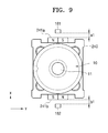
- FIG. 9 is a plan view of the camera module of FIG. 2 illustrating the second sub-moving frame 240 , according to an embodiment.
- FIGS. 10A and 10B are plan views that illustrate the second sub-moving frame 240 of FIG. 9 moved in the first direction (x-axis direction), according to embodiments.
- the second sub-moving frame 240 mounts the lens barrel 10 and is moved in the first direction and the second direction.
- the second sub-moving frame 240 includes third magnets 241 a and 241 b disposed at two sides in the first direction (x-axis direction).
- the fixed frame 100 includes third sensors 161 and 162 spaced apart from each other in the first direction (x-axis direction) to respectively correspond to the third magnets 241 a and 241 b .
- the third sensors 161 and 162 are spaced apart from each other by a predetermined distance.
- a distance between the third magnet 241 a and the third sensor 161 in the first direction (x-axis direction) is a 1
- a distance between the other third magnet 241 b and the other third sensor 162 in the first direction (x-axis direction) is b 1
- the distances a 1 and b 1 vary according to movement of the second sub-moving frame 240 in the first direction (x-axis direction).
- a sum of a 1 +b 1 remains constant.
- the second sub-moving frame 240 is moved in the first direction (x-axis direction) such that the third magnet 241 a may be spaced apart from the third sensor 161 in the first direction (x-axis direction) by 0.7 mm, and the third magnet 241 b may be spaced apart from the third sensor 162 in the first direction (x-axis direction) by 0.8 mm.
- the third magnet 241 a may be spaced apart from the third sensor 161 in the first direction (x-axis direction) by 0.7 mm
- the third magnet 241 b may be spaced apart from the third sensor 162 in the first direction (x-axis direction) by 0.8 mm.
- the second sub-moving frame 240 is moved in the first direction (x-axis direction) such that the third magnet 241 a may be spaced apart from the third sensor 161 in the first direction (x-axis direction) by 0.6 mm, and the third magnet 241 b may be spaced apart from the third sensor 162 in the first direction (x-axis direction) by 0.9 mm.
- FIG. 11A is a graph showing a magnetic flux density detected by the third sensors 161 and 162 of FIG. 10A according to positions of the third magnets 241 a and 241 b in the second direction (y-axis direction)
- FIG. 11B is a graph showing a magnetic flux density detected by the third sensors 161 and 162 of FIG. 10B according to position of the third magnets 241 a and 241 b in the second direction (y-axis direction).
- FIG. 12 is a graph showing a third magnetic flux density which is a sum of first and second magnetic flux densities detected by the third sensors 161 and 162 illustrated in FIGS. 11A and 11B , according to a position of the second sub-moving frame 240 in the second direction (y-axis direction), according to an embodiment.
- patterns of the first and second magnetic flux densities detected by the third 161 and 162 vary according to distances between the third sensors 161 and 162 and the third magnets 241 a and 241 b in the first direction (x-axis direction).
- a pattern of the first magnetic flux density detected by the third sensor 161 when the distance between the third sensor 161 and the third magnet 241 a along the first direction (x-axis direction) is 0.7 mm is different from a pattern of the second magnetic flux density detected by the third sensor 162 when the distance between the third sensor 162 and the third magnet 241 b in the first direction (x-axis direction) is 0.8 mm.
- a pattern of the first magnetic flux density detected by the third sensor 161 when the distance between the third sensor 161 and the third magnet 241 a along the first direction (x-axis direction) is 0.9 mm is different from a pattern of the second magnetic flux density detected by the third sensor 162 when the distance between the third sensor 162 and the third magnet 241 b along the first direction (x-axis direction) is 0.9 mm.
- the third magnetic density (sum 1 , sum 2 ) which is a sum of the magnetic flux densities detected by the third sensors 161 and 162 exhibit substantially the same patterns, regardless of the position of the second sub-moving frame 240 along the first direction (x-axis direction).
- the third magnetic flux density (sum 1 ) is a sum of the first magnetic flux density detected by the third sensor 161 and the second magnetic flux density detected by using the third sensor 162 of FIG. 11A
- the third magnetic flux density (sum 2 ) is a sum of the first magnetic flux density detected by the third sensor 161 and the second magnetic flux density detected by the third sensor 162 of FIG. 11B .
- the third magnetic flux density (sum 1 , sum 2 ) which is a sum of the first magnetic flux density and the second magnetic flux density has a constant value regardless of a movement of the first magnet 211 in the first direction (x-axis direction).
- the third magnetic flux density (sum 1 , sum 2 ) having a constant value according to a position of the third magnets 241 a and 241 b in the second direction (y-axis direction) means that even when the third magnets 241 a and 241 b are moved in the first direction (x-axis direction), an error of the third magnetic flux density detected at the same position in the second direction (y-axis direction) is less than up to 2.9%.
- a third magnetic flux density which is a sum of magnetic flux densities detected by the third sensor 161 and the third sensor 162 is constant according to a position of the third magnets 241 a and 241 b in the second direction (y-axis direction).
- a position information generating unit may compare the third magnetic flux density which is the sum of the first magnetic flux density detected by the third sensor 161 and the second magnetic flux density detected by the third sensor 162 with a predetermined reference value, thereby generating position information of the third magnets 241 a and 241 b in the second direction (y-axis direction).
- the position information generating unit may compare the third magnetic flux density which is the sum of the first magnetic flux density detected by the third sensor 161 and the second magnetic flux density detected by using the third sensors 162 with a predetermined reference value according to the position of the third magnets 241 a and 241 b in the second direction (y-axis direction), thereby generating or determining position information of the third magnets 241 a and 241 b in the second direction (y-axis direction).
- position information of the second sub-moving frame 240 may be generated or determined based on position information of the third magnets 241 a and 241 b in the second direction (y-axis direction).
- the reference value may be a preset value based on the third magnetic flux density in the second direction illustrated in FIG. 10 .
- the position information generating unit may include a memory unit that stores a preset reference value according to movement of the third magnets 241 a and 241 b in the second direction (y-axis direction) and a position determining unit that determines position information of the third magnets 241 a and 241 b along the second direction (y-axis direction) by comparing the third magnetic flux density with the reference value.
- a magnetic flux density is used as an example of a detection signal detected by a magnetic sensor in the current embodiment.
- an electrical signal or the like may also be used.
- Table 1 below shows results of a position movement of the moving frame 200 of the camera module of FIG. 2 in a positive direction or a negative direction of the second direction (y-axis direction).
- position information of the third magnets 241 a and 241 b in the second direction (y-axis direction) generated based on the sum of detection signals detected by the third sensors 161 and 162 was used.
- FIG. 13 is a cross-sectional perspective view of the camera module of FIG. 1 cut along a line XIII-XIII′; and FIG. 14 is a cross-sectional perspective view of the camera module of FIG. 1 cut along a line XIV-XIV′.
- the first driving coil 110 and the first sensor 140 are included in the first sidewall 101 of the fixed frame 100 , and the first magnet 211 is disposed in the moving frame 200 to correspond to the first driving coil 110 and the first sensor 140 .
- the first driving coil 110 and the first magnet 211 are spaced apart from each other in the second direction (y-axis direction) perpendicular to an optical axis.
- the second driving coil 120 and the second sensor 150 are included in the third sidewall 103 of the fixed frame 100 , and the second magnet 231 is disposed in the moving frame 200 to correspond to the second driving coil 120 and the second sensor 150 .
- the second driving coil 120 and the second sensor 150 are also spaced apart from each other in the second direction (y-axis direction) perpendicular to the optical axis.
- the first driving coil 110 and the first sensor 140 are electrically connected to the first printed circuit board 301
- the second driving coil 120 and the second sensor 150 are electrically connected to the second printed circuit board 302 .
- the third driving coils 130 a and 130 b and the third sensors 161 and 162 are included the second sidewall 102 and the fourth sidewall 104 of the fixed frame 200 , respectively, and the third magnets 241 a and 241 b are disposed in the moving frame 200 to correspond to the third driving coils 130 a and 130 b and the third sensors 161 and 162 .
- the third driving coils 130 a and 130 b and the third magnets 241 a and 241 b are spaced apart from each other in the first direction (x-axis direction) that is perpendicular to the optical axis.
- the pair of the driving coils 130 a and 130 b and the pair of the third sensors 161 and 162 are electrically connected to the second printed circuit board 302 .
- the first and second magnets 211 and 231 and third magnets 241 a and 241 b that are spaced apart from the first and second 110 and 120 and the third driving coils 130 a and 130 b in a direction perpendicular to the optical axis are moved in a predetermined direction.
- the first magnet 211 is moved in the optical axis direction (z-axis direction).
- the second magnet 231 is moved in the first direction (x-axis direction)
- the third magnets 241 a and 241 b are moved in the second direction (y-axis direction).
- the current may be individually or simultaneously supplied to the first and second driving coils 110 and 120 and the third driving coils 130 a and 130 b.
- the fixed frame 100 to which the first and second printed circuit boards 301 and 302 are electrically connected is fixed to the base 20 and is not moved, and thus, tension variation of the first and second printed circuit boards 301 and 302 is not caused while the moving frame 200 to which the first and second magnets 211 and 231 and the third magnets 241 a and 241 b are mounted is moved. Accordingly, the moving frame 200 may be accurately moved without being affected by the tension variation applied to the first and second printed circuit boards 301 and 302 .
- a thickness of the camera module in the optical axis direction may be reduced.
- the thickness of the camera module in the optical axis direction may not increase.
- the first sub-moving frame 230 is moved in the first direction (x-axis direction), and the second sub-moving frame 240 is moved in the second direction (y-axis direction), but the embodiments are not limited thereto.
- the first sub-moving frame 230 may be moved in the second direction (y-axis direction), and the second sub-moving frame 240 may be moved in the first direction (x-axis direction).
- VCM voice coil motor
- other methods for driving the moving frame 200 for example, an ultrasonic wave motor method using a piezoelectric element or a method of driving the moving frame 200 by applying a current to a shape memory alloy may also be used.
- a printed circuit board is connected to a fixed frame for three-axis driving, thereby providing an Auto Focus (AF) function and an Optical Image Stabilization (OIS) function whereby a lens may be precisely moved and a tension variation in the printed circuit board may be prevented or minimized.
- AF Auto Focus
- OIS Optical Image Stabilization
- nism and “element” are used broadly and are not limited to mechanical or physical embodiments, but can include software routines in conjunction with processors, etc.
Landscapes
- Physics & Mathematics (AREA)
- General Physics & Mathematics (AREA)
- Engineering & Computer Science (AREA)
- Multimedia (AREA)
- Signal Processing (AREA)
- Optics & Photonics (AREA)
- Adjustment Of Camera Lenses (AREA)
- Lens Barrels (AREA)
- Transforming Light Signals Into Electric Signals (AREA)
- Credit Cards Or The Like (AREA)
Priority Applications (1)
| Application Number | Priority Date | Filing Date | Title |
|---|---|---|---|
| US15/232,995 US9832383B2 (en) | 2013-08-19 | 2016-08-10 | Camera module having a moving frame |
Applications Claiming Priority (2)
| Application Number | Priority Date | Filing Date | Title |
|---|---|---|---|
| KR10-2013-0098132 | 2013-08-19 | ||
| KR1020130098132A KR102166329B1 (ko) | 2013-08-19 | 2013-08-19 | 카메라 모듈 |
Related Child Applications (1)
| Application Number | Title | Priority Date | Filing Date |
|---|---|---|---|
| US15/232,995 Continuation US9832383B2 (en) | 2013-08-19 | 2016-08-10 | Camera module having a moving frame |
Publications (2)
| Publication Number | Publication Date |
|---|---|
| US20150049209A1 US20150049209A1 (en) | 2015-02-19 |
| US9438801B2 true US9438801B2 (en) | 2016-09-06 |
Family
ID=50382206
Family Applications (2)
| Application Number | Title | Priority Date | Filing Date |
|---|---|---|---|
| US14/182,544 Active 2034-07-17 US9438801B2 (en) | 2013-08-19 | 2014-02-18 | Camera module having a moving frame |
| US15/232,995 Active US9832383B2 (en) | 2013-08-19 | 2016-08-10 | Camera module having a moving frame |
Family Applications After (1)
| Application Number | Title | Priority Date | Filing Date |
|---|---|---|---|
| US15/232,995 Active US9832383B2 (en) | 2013-08-19 | 2016-08-10 | Camera module having a moving frame |
Country Status (11)
| Country | Link |
|---|---|
| US (2) | US9438801B2 (ko) |
| EP (4) | EP3793187B1 (ko) |
| KR (1) | KR102166329B1 (ko) |
| AU (1) | AU2014309689B2 (ko) |
| BR (1) | BR112015029406B1 (ko) |
| ES (2) | ES2946491T3 (ko) |
| FI (1) | FI3940441T3 (ko) |
| HU (2) | HUE062046T2 (ko) |
| PL (2) | PL3793187T3 (ko) |
| PT (1) | PT3940441T (ko) |
| WO (1) | WO2015026078A1 (ko) |
Cited By (12)
| Publication number | Priority date | Publication date | Assignee | Title |
|---|---|---|---|---|
| US9885881B2 (en) | 2014-03-07 | 2018-02-06 | Jahwa Electronics Co., Ltd. | Camera lens module |
| US10078196B2 (en) | 2015-09-17 | 2018-09-18 | Samsung Electronics Co., Ltd. | Camera module including multi-lens and electronic device having the same |
| US10154182B2 (en) | 2015-11-05 | 2018-12-11 | Samsung Electronics Co., Ltd. | Camera module including multiple camera lenses, electronic device having the same, and method for controlling operation of camera module |
| US20210080683A1 (en) * | 2019-09-12 | 2021-03-18 | Tdk Taiwan Corp. | Optical element driving mechanism |
| US11277548B2 (en) * | 2019-04-30 | 2022-03-15 | Samsung Electro-Mechanics Co., Ltd. | Camera module |
| US11287602B2 (en) * | 2017-06-13 | 2022-03-29 | Olympus Corporation | Optical unit and endoscope |
| US20220311916A1 (en) * | 2020-07-31 | 2022-09-29 | Samsung Electronics Co., Ltd. | Camera module and electronic device including the same |
| US11662548B2 (en) | 2020-03-31 | 2023-05-30 | Largan Digital Co., Ltd. | Lens driving apparatus and electronic device |
| US11709335B2 (en) | 2019-10-16 | 2023-07-25 | Samsung Electronics Co., Ltd | Camera module including position sensor |
| US11822210B2 (en) | 2019-10-16 | 2023-11-21 | Samsung Electronics Co., Ltd. | Electronic device including camera |
| US11982866B2 (en) * | 2019-06-14 | 2024-05-14 | Tdk Taiwan Corp. | Optical element driving mechanism having movable portion for holding lens |
| US12058426B2 (en) | 2021-02-23 | 2024-08-06 | Samsung Electronics Co., Ltd. | Camera module and electronic device including the same |
Families Citing this family (69)
| Publication number | Priority date | Publication date | Assignee | Title |
|---|---|---|---|---|
| KR101300353B1 (ko) * | 2011-12-22 | 2013-08-28 | 삼성전기주식회사 | 손떨림 보정장치 |
| WO2015015920A1 (ja) * | 2013-07-29 | 2015-02-05 | 富士フイルム株式会社 | 撮像モジュールの製造方法及び撮像モジュールの製造装置 |
| US9372352B2 (en) | 2013-08-23 | 2016-06-21 | Samsung Electro-Mechanics Co., Ltd. | Lens driving device and camera module including the same |
| US9531953B2 (en) | 2013-10-11 | 2016-12-27 | Samsung Electro-Mechanics Co., Ltd. | Camera module and portable electronic device including the same |
| US10133086B2 (en) | 2013-10-25 | 2018-11-20 | Jahwa Electronics Co., Ltd. | Camera lens module |
| US9964778B2 (en) | 2013-10-25 | 2018-05-08 | Jahwa Electronics Co., Ltd. | Camera lens module |
| KR101666087B1 (ko) * | 2013-10-25 | 2016-10-14 | 자화전자(주) | 카메라 렌즈 모듈 |
| WO2015060637A1 (ko) | 2013-10-25 | 2015-04-30 | 자화전자(주) | 카메라 렌즈 모듈 |
| KR102179952B1 (ko) * | 2013-11-25 | 2020-11-17 | 삼성전자주식회사 | 광학조절장치 |
| US9618770B2 (en) * | 2014-04-11 | 2017-04-11 | Samsung Electro-Mechanics Co., Ltd. | Camera module with function of auto-focus and image stabilize |
| US9578242B2 (en) | 2014-04-11 | 2017-02-21 | Samsung Electro-Mechanics Co., Ltd. | Camera module |
| KR101693462B1 (ko) * | 2014-04-11 | 2017-01-09 | 삼성전기주식회사 | 카메라 모듈 |
| US9921458B2 (en) | 2014-05-30 | 2018-03-20 | Samsung Electro-Mechanics Co., Ltd. | Camera module |
| US9791674B1 (en) * | 2015-02-06 | 2017-10-17 | Apple Inc. | Miniature camera zoom actuator with magnet-induced friction |
| KR102494346B1 (ko) * | 2015-04-10 | 2023-02-01 | 삼성전기주식회사 | 렌즈 구동 장치 및 이를 포함하는 카메라 모듈 |
| KR101832568B1 (ko) * | 2015-05-20 | 2018-02-27 | 삼성전기주식회사 | 카메라 모듈 |
| US20160341975A1 (en) * | 2015-05-21 | 2016-11-24 | Jahwa Electronics Co., Ltd. | Camera lens module |
| KR101694881B1 (ko) * | 2015-06-23 | 2017-01-23 | 자화전자(주) | 카메라 렌즈 모듈 |
| KR101740814B1 (ko) * | 2015-10-14 | 2017-05-26 | 삼성전기주식회사 | 카메라 모듈 |
| KR102426513B1 (ko) | 2015-12-14 | 2022-07-28 | 삼성전자주식회사 | 렌즈 어셈블리 및 그를 포함하는 전자 장치 |
| US11523034B2 (en) | 2016-02-10 | 2022-12-06 | Microsoft Technology Licensing, Llc | Imaging apparatus |
| KR101704498B1 (ko) * | 2016-03-10 | 2017-02-09 | 자화전자(주) | 3위치 지지구조의 자동초점 조절장치 |
| KR102348365B1 (ko) * | 2016-05-03 | 2022-01-10 | 삼성전자주식회사 | 카메라 모듈을 포함하는 전자 장치 |
| US9958756B2 (en) * | 2016-05-20 | 2018-05-01 | Tdk Taiwan Corp. | Camera module and image capturing unit thereof |
| KR101978946B1 (ko) * | 2016-06-09 | 2019-05-15 | 자화전자(주) | 자동초점 조절장치 |
| CN111522183B (zh) * | 2016-07-29 | 2021-12-31 | 台湾东电化股份有限公司 | 镜头驱动装置 |
| US10317779B2 (en) | 2016-08-16 | 2019-06-11 | Microsoft Technology Licensing, Llc | Imaging apparatus |
| WO2018223382A1 (en) * | 2017-06-09 | 2018-12-13 | Huawei Technologies Co., Ltd. | Lens actuator with ois and af function |
| CN109391750B (zh) * | 2017-08-05 | 2023-05-12 | 宁波舜宇光电信息有限公司 | 一定焦摄像模组 |
| JP6630331B2 (ja) | 2017-10-23 | 2020-01-15 | 新思考電機有限公司 | レンズ駆動装置、カメラ装置及び電子機器 |
| US11982864B2 (en) | 2017-10-23 | 2024-05-14 | New Shicoh Motor Co., Ltd. | Lens driving device, camera device, and electronic apparatus |
| KR102470853B1 (ko) | 2018-01-31 | 2022-11-28 | 삼성전자주식회사 | 카메라 모듈 |
| CN209446872U (zh) * | 2018-05-30 | 2019-09-27 | 台湾东电化股份有限公司 | 光学元件驱动机构 |
| CN110784625B (zh) * | 2018-07-25 | 2022-04-15 | 台湾东电化股份有限公司 | 感光组件驱动机构 |
| CN209803436U (zh) * | 2018-07-25 | 2019-12-17 | 台湾东电化股份有限公司 | 光学组件驱动机构 |
| KR102562142B1 (ko) * | 2018-08-09 | 2023-08-01 | 삼성전기주식회사 | 카메라 모듈 |
| CN111830658A (zh) * | 2019-04-19 | 2020-10-27 | 新思考电机有限公司 | 透镜驱动装置、照相装置以及电子设备 |
| US11573391B2 (en) | 2019-04-30 | 2023-02-07 | Samsung Electro-Mechanics Co., Ltd. | Camera module |
| CN211698530U (zh) * | 2019-04-30 | 2020-10-16 | 三星电机株式会社 | 相机模块 |
| US12523919B2 (en) | 2019-08-16 | 2026-01-13 | Samsung Electro-Mechanics Co., Ltd. | Camera module |
| CN112752013B (zh) * | 2019-10-30 | 2025-02-11 | 晋城三赢精密电子有限公司 | 防抖装置、摄像头模组及电子装置 |
| KR102327730B1 (ko) | 2019-12-10 | 2021-11-17 | 삼성전기주식회사 | 카메라 모듈 |
| KR102272591B1 (ko) | 2019-12-10 | 2021-07-05 | 삼성전기주식회사 | 카메라 모듈 |
| CN113132610A (zh) * | 2019-12-31 | 2021-07-16 | 格科微电子(上海)有限公司 | 光学防抖的摄像头模组和数码装置 |
| KR102920538B1 (ko) * | 2020-01-06 | 2026-01-30 | 엘지이노텍 주식회사 | 카메라 엑추에이터 및 이를 포함하는 카메라 장치 |
| JP6809738B2 (ja) * | 2020-01-10 | 2021-01-06 | 新シコー科技株式会社 | レンズ駆動装置、カメラ装置及び電子機器 |
| KR102306710B1 (ko) | 2020-02-24 | 2021-09-30 | 삼성전기주식회사 | 카메라 모듈 |
| US11835788B2 (en) | 2020-02-28 | 2023-12-05 | Samsung Electro-Mechanics Co., Ltd. | Camera module and electronic device including the same |
| CN113530774B (zh) * | 2020-03-31 | 2022-09-06 | 斯玛特技研有限公司 | 使用sma线的三轴对焦马达 |
| US20210373353A1 (en) * | 2020-05-28 | 2021-12-02 | New Shicoh Motor Co., Ltd. | Lens driving device, camera device, and electronic apparatus |
| KR102883045B1 (ko) * | 2020-05-29 | 2025-11-07 | 엘지이노텍 주식회사 | 카메라 엑추에이터 및 이를 포함하는 카메라 장치 |
| KR102422882B1 (ko) * | 2020-07-10 | 2022-07-20 | 주식회사 엠씨넥스 | 단순한 2축 손떨림보정 구조를 가진 카메라 장치 |
| KR102258022B1 (ko) * | 2020-09-01 | 2021-05-28 | 삼성전자 주식회사 | 상대 위치 결정을 위한 센서 장치와 그 센서 장치를 포함하는 전자 장치 및 상대 위치를 결정하기 위한 방법 |
| US11803099B2 (en) * | 2020-11-18 | 2023-10-31 | Samsung Electro-Mechanics Co., Ltd. | Camera module |
| KR102728736B1 (ko) * | 2021-02-05 | 2024-11-11 | 삼성전기주식회사 | 카메라용 액추에이터, 카메라 모듈 및 이를 포함하는 휴대용 전자기기 |
| KR102563645B1 (ko) * | 2021-04-21 | 2023-08-04 | 자화전자(주) | 카메라용 액추에이터 |
| CN113923343B (zh) * | 2021-04-29 | 2022-09-27 | 荣耀终端有限公司 | 驱动装置、摄像模组及电子设备 |
| US11910090B2 (en) * | 2021-04-30 | 2024-02-20 | Samsung Electro-Mechanics Co., Ltd. | Camera module actuator for optical image stabilization with movable image sensor |
| CN113194602B (zh) * | 2021-05-10 | 2025-02-07 | 中山联合光电科技股份有限公司 | 一种柔性电路板、光学变焦镜头及电子设备 |
| CN113301230B (zh) * | 2021-05-20 | 2023-03-24 | 昆山联滔电子有限公司 | 兼具影像补偿与自动对焦功能的摄像装置 |
| CN120034736A (zh) * | 2021-08-19 | 2025-05-23 | 谷歌有限责任公司 | 用于图像传感器的稳定组件 |
| EP4209839A4 (en) | 2021-11-17 | 2024-04-10 | Samsung Electronics Co., Ltd. | CAMERA MODULE AND ELECTRONIC DEVICE THEREOF |
| CN116490822A (zh) * | 2021-11-17 | 2023-07-25 | 三星电子株式会社 | 相机模块和包括该相机模块的电子装置 |
| CN114244980B (zh) | 2021-12-06 | 2024-06-28 | 昆山联滔电子有限公司 | 摄像模组与长行程摄像结构 |
| KR102445116B1 (ko) * | 2021-12-21 | 2022-09-20 | 자화전자(주) | 카메라용 액추에이터 및 이를 포함하는 카메라 모듈 |
| KR20230109370A (ko) * | 2022-01-13 | 2023-07-20 | 삼성전기주식회사 | 흔들림 보정용 액추에이터 및 이를 포함하는 카메라 모듈 |
| US12334793B2 (en) * | 2022-05-31 | 2025-06-17 | Samsung Electro-Mechanics Co., Ltd. | Actuator for camera |
| KR20240101125A (ko) * | 2022-12-23 | 2024-07-02 | 삼성전기주식회사 | 흔들림 보정용 액추에이터 및 이를 포함하는 카메라 모듈 |
| TWI856484B (zh) | 2023-01-06 | 2024-09-21 | 大立光電股份有限公司 | 相機模組與電子裝置 |
Citations (27)
| Publication number | Priority date | Publication date | Assignee | Title |
|---|---|---|---|---|
| JP2004163748A (ja) | 2002-11-14 | 2004-06-10 | Fuji Photo Film Co Ltd | カメラ |
| US20050174465A1 (en) | 2004-02-10 | 2005-08-11 | Hiroshi Akada | Image-blur correction apparatus, lens apparatus and optical device |
| US20050185531A1 (en) * | 2003-12-17 | 2005-08-25 | Samsung Electronics Co., Ltd. | Magnetic circuit and optical recording and/or reproducing apparatus employing the same |
| JP2006184544A (ja) | 2004-12-27 | 2006-07-13 | Sony Corp | レンズ装置、およびレンズ装置を備える撮像装置 |
| US20060257129A1 (en) * | 2005-05-11 | 2006-11-16 | Konica Minolta Photo Imaging, Inc. | Image sensing apparatus equipped with anti-shake mechanism |
| US20070133967A1 (en) * | 2005-12-08 | 2007-06-14 | Sony Corporation | Image stabilizer, lens device and imager apparatus |
| US20100091120A1 (en) | 2008-10-14 | 2010-04-15 | Nidec Sankyo Corporation | Optical unit with shake correcting function |
| US20100134902A1 (en) * | 2008-11-28 | 2010-06-03 | Sony Corporation | Lens barrel and imaging apparatus |
| US20110096178A1 (en) | 2008-05-14 | 2011-04-28 | Hysonic. Co., Ltd. | Photography device with anti-shake function |
| US20110217029A1 (en) | 2010-03-04 | 2011-09-08 | Fu-Yuan Wu | Anti-shake structure for auto-focus modular |
| US20110236008A1 (en) | 2010-03-23 | 2011-09-29 | Samsung Electro-Mechanics Co., Ltd. | Camera module |
| US20120082442A1 (en) | 2010-10-04 | 2012-04-05 | Samsung Electro Mechanics Co., Ltd. | Image photographing device having function for compensating for hand vibration |
| US20120105960A1 (en) * | 2010-10-28 | 2012-05-03 | Samsung Electronics Co., Ltd. | Optical device including adjustable optical element |
| US20120147258A1 (en) | 2010-12-14 | 2012-06-14 | Lg Innotek Co., Ltd. | Camera module |
| KR20120067653A (ko) | 2010-12-16 | 2012-06-26 | 엘지이노텍 주식회사 | 3차원 입체 카메라 모듈 |
| US20120229926A1 (en) * | 2009-11-18 | 2012-09-13 | Nidec Sankyo Corporation | Lens drive device |
| US20130016427A1 (en) * | 2011-07-15 | 2013-01-17 | Mitsumi Electric Co., Ltd | Lens holder driving device capable of avoiding deleterious effect on hall elements |
| US20130027790A1 (en) * | 2011-07-26 | 2013-01-31 | Samsung Electronics Co., Ltd. | Position sensor assembly and optical device including the same |
| US20130162849A1 (en) * | 2011-12-27 | 2013-06-27 | Hon Hai Precision Industry Co., Ltd. | Auto-focusing camera module and imaging method using same |
| US20130170039A1 (en) * | 2011-12-16 | 2013-07-04 | Canon Kabushiki Kaisha | Image stabilization apparatus, optical apparatus, and imaging apparatus |
| US20130177301A1 (en) * | 2012-01-05 | 2013-07-11 | Sony Corporation | Image blur correction device and imaging apparatus |
| US20130201559A1 (en) * | 2009-12-25 | 2013-08-08 | Nidec Sankyo Corporation | Lens Drive Device |
| US20130258172A1 (en) * | 2012-03-30 | 2013-10-03 | Jahwa Electronics Co., Ltd. | Apparatus and method of controlling drive of camera module |
| US8818181B1 (en) | 2013-08-19 | 2014-08-26 | Samsung Electronics Co., Ltd. | Camera module, and position detector and position detection method used in the camera module |
| US20150207968A1 (en) * | 2012-07-09 | 2015-07-23 | Lg Innotek Co., Ltd. | Camera module |
| US20150229843A1 (en) * | 2012-10-31 | 2015-08-13 | Fujifilm Corporation | Camera module having anti-shake mechanism |
| US20150370086A1 (en) * | 2012-12-11 | 2015-12-24 | Nidec Sankyo Corporation | Optical device |
Family Cites Families (3)
| Publication number | Priority date | Publication date | Assignee | Title |
|---|---|---|---|---|
| CN101959012B (zh) * | 2009-07-17 | 2013-08-21 | 鸿富锦精密工业(深圳)有限公司 | 相机模组 |
| KR101300353B1 (ko) * | 2011-12-22 | 2013-08-28 | 삼성전기주식회사 | 손떨림 보정장치 |
| TWI546604B (zh) * | 2012-07-05 | 2016-08-21 | 鴻海精密工業股份有限公司 | 致動器及具有該致動器之相機模組 |
-
2013
- 2013-08-19 KR KR1020130098132A patent/KR102166329B1/ko active Active
-
2014
- 2014-02-18 US US14/182,544 patent/US9438801B2/en active Active
- 2014-03-11 ES ES21195256T patent/ES2946491T3/es active Active
- 2014-03-11 EP EP20205871.5A patent/EP3793187B1/en active Active
- 2014-03-11 EP EP21195256.9A patent/EP3940441B1/en active Active
- 2014-03-11 HU HUE21195256A patent/HUE062046T2/hu unknown
- 2014-03-11 FI FIEP21195256.9T patent/FI3940441T3/fi active
- 2014-03-11 PL PL20205871.5T patent/PL3793187T3/pl unknown
- 2014-03-11 PT PT211952569T patent/PT3940441T/pt unknown
- 2014-03-11 PL PL21195256.9T patent/PL3940441T3/pl unknown
- 2014-03-11 EP EP14158883.0A patent/EP2852148B1/en active Active
- 2014-03-11 ES ES20205871T patent/ES2914502T3/es active Active
- 2014-03-11 HU HUE20205871A patent/HUE058976T2/hu unknown
- 2014-03-11 EP EP23162841.3A patent/EP4220266B1/en active Active
- 2014-08-05 AU AU2014309689A patent/AU2014309689B2/en active Active
- 2014-08-05 BR BR112015029406-5A patent/BR112015029406B1/pt active IP Right Grant
- 2014-08-05 WO PCT/KR2014/007209 patent/WO2015026078A1/en not_active Ceased
-
2016
- 2016-08-10 US US15/232,995 patent/US9832383B2/en active Active
Patent Citations (28)
| Publication number | Priority date | Publication date | Assignee | Title |
|---|---|---|---|---|
| JP2004163748A (ja) | 2002-11-14 | 2004-06-10 | Fuji Photo Film Co Ltd | カメラ |
| US20050185531A1 (en) * | 2003-12-17 | 2005-08-25 | Samsung Electronics Co., Ltd. | Magnetic circuit and optical recording and/or reproducing apparatus employing the same |
| US20050174465A1 (en) | 2004-02-10 | 2005-08-11 | Hiroshi Akada | Image-blur correction apparatus, lens apparatus and optical device |
| JP2006184544A (ja) | 2004-12-27 | 2006-07-13 | Sony Corp | レンズ装置、およびレンズ装置を備える撮像装置 |
| US20060257129A1 (en) * | 2005-05-11 | 2006-11-16 | Konica Minolta Photo Imaging, Inc. | Image sensing apparatus equipped with anti-shake mechanism |
| US20070133967A1 (en) * | 2005-12-08 | 2007-06-14 | Sony Corporation | Image stabilizer, lens device and imager apparatus |
| US20110096178A1 (en) | 2008-05-14 | 2011-04-28 | Hysonic. Co., Ltd. | Photography device with anti-shake function |
| US20100091120A1 (en) | 2008-10-14 | 2010-04-15 | Nidec Sankyo Corporation | Optical unit with shake correcting function |
| US20100134902A1 (en) * | 2008-11-28 | 2010-06-03 | Sony Corporation | Lens barrel and imaging apparatus |
| US20120229926A1 (en) * | 2009-11-18 | 2012-09-13 | Nidec Sankyo Corporation | Lens drive device |
| US20130201559A1 (en) * | 2009-12-25 | 2013-08-08 | Nidec Sankyo Corporation | Lens Drive Device |
| US20110217029A1 (en) | 2010-03-04 | 2011-09-08 | Fu-Yuan Wu | Anti-shake structure for auto-focus modular |
| US20110236008A1 (en) | 2010-03-23 | 2011-09-29 | Samsung Electro-Mechanics Co., Ltd. | Camera module |
| US20120082442A1 (en) | 2010-10-04 | 2012-04-05 | Samsung Electro Mechanics Co., Ltd. | Image photographing device having function for compensating for hand vibration |
| US20120105960A1 (en) * | 2010-10-28 | 2012-05-03 | Samsung Electronics Co., Ltd. | Optical device including adjustable optical element |
| US20120147258A1 (en) | 2010-12-14 | 2012-06-14 | Lg Innotek Co., Ltd. | Camera module |
| US20130265394A1 (en) | 2010-12-16 | 2013-10-10 | Haekeun Lim | 3d stereoscopic camera module |
| KR20120067653A (ko) | 2010-12-16 | 2012-06-26 | 엘지이노텍 주식회사 | 3차원 입체 카메라 모듈 |
| US20130016427A1 (en) * | 2011-07-15 | 2013-01-17 | Mitsumi Electric Co., Ltd | Lens holder driving device capable of avoiding deleterious effect on hall elements |
| US20130027790A1 (en) * | 2011-07-26 | 2013-01-31 | Samsung Electronics Co., Ltd. | Position sensor assembly and optical device including the same |
| US20130170039A1 (en) * | 2011-12-16 | 2013-07-04 | Canon Kabushiki Kaisha | Image stabilization apparatus, optical apparatus, and imaging apparatus |
| US20130162849A1 (en) * | 2011-12-27 | 2013-06-27 | Hon Hai Precision Industry Co., Ltd. | Auto-focusing camera module and imaging method using same |
| US20130177301A1 (en) * | 2012-01-05 | 2013-07-11 | Sony Corporation | Image blur correction device and imaging apparatus |
| US20130258172A1 (en) * | 2012-03-30 | 2013-10-03 | Jahwa Electronics Co., Ltd. | Apparatus and method of controlling drive of camera module |
| US20150207968A1 (en) * | 2012-07-09 | 2015-07-23 | Lg Innotek Co., Ltd. | Camera module |
| US20150229843A1 (en) * | 2012-10-31 | 2015-08-13 | Fujifilm Corporation | Camera module having anti-shake mechanism |
| US20150370086A1 (en) * | 2012-12-11 | 2015-12-24 | Nidec Sankyo Corporation | Optical device |
| US8818181B1 (en) | 2013-08-19 | 2014-08-26 | Samsung Electronics Co., Ltd. | Camera module, and position detector and position detection method used in the camera module |
Non-Patent Citations (2)
| Title |
|---|
| European Search Report issued for related application EP 14158883.0, Aug. 17, 2015, 3 pages. |
| PCT Search Report and Written Opinion issued for PCT/KR2014/007209 (Nov. 19, 2014). |
Cited By (20)
| Publication number | Priority date | Publication date | Assignee | Title |
|---|---|---|---|---|
| US9885881B2 (en) | 2014-03-07 | 2018-02-06 | Jahwa Electronics Co., Ltd. | Camera lens module |
| US10078196B2 (en) | 2015-09-17 | 2018-09-18 | Samsung Electronics Co., Ltd. | Camera module including multi-lens and electronic device having the same |
| US10154182B2 (en) | 2015-11-05 | 2018-12-11 | Samsung Electronics Co., Ltd. | Camera module including multiple camera lenses, electronic device having the same, and method for controlling operation of camera module |
| US11287602B2 (en) * | 2017-06-13 | 2022-03-29 | Olympus Corporation | Optical unit and endoscope |
| US11736788B2 (en) | 2019-04-30 | 2023-08-22 | Samsung Electro-Mechanics Co., Ltd. | Camera module |
| US11277548B2 (en) * | 2019-04-30 | 2022-03-15 | Samsung Electro-Mechanics Co., Ltd. | Camera module |
| US11570337B2 (en) | 2019-04-30 | 2023-01-31 | Samsung Electro-Mechanics Co., Ltd. | Camera module |
| US11575812B2 (en) | 2019-04-30 | 2023-02-07 | Samsung Electro-Mechanics Co., Ltd. | Camera module |
| US11982866B2 (en) * | 2019-06-14 | 2024-05-14 | Tdk Taiwan Corp. | Optical element driving mechanism having movable portion for holding lens |
| US20210080683A1 (en) * | 2019-09-12 | 2021-03-18 | Tdk Taiwan Corp. | Optical element driving mechanism |
| US11624936B2 (en) * | 2019-09-12 | 2023-04-11 | Tdk Taiwan Corp. | Optical element driving mechanism |
| US11709335B2 (en) | 2019-10-16 | 2023-07-25 | Samsung Electronics Co., Ltd | Camera module including position sensor |
| US11822210B2 (en) | 2019-10-16 | 2023-11-21 | Samsung Electronics Co., Ltd. | Electronic device including camera |
| US11662548B2 (en) | 2020-03-31 | 2023-05-30 | Largan Digital Co., Ltd. | Lens driving apparatus and electronic device |
| US11871099B2 (en) * | 2020-07-31 | 2024-01-09 | Samsung Electronics Co., Ltd. | Camera module and electronic device including the same |
| US20240147041A1 (en) * | 2020-07-31 | 2024-05-02 | Samsung Electronics Co., Ltd. | Camera module and electronic device including the same |
| US20220311916A1 (en) * | 2020-07-31 | 2022-09-29 | Samsung Electronics Co., Ltd. | Camera module and electronic device including the same |
| US12219232B2 (en) * | 2020-07-31 | 2025-02-04 | Samsung Electronics Co., Ltd. | Camera module and electronic device including the same |
| US12058426B2 (en) | 2021-02-23 | 2024-08-06 | Samsung Electronics Co., Ltd. | Camera module and electronic device including the same |
| US12513378B2 (en) | 2021-02-23 | 2025-12-30 | Samsung Electronics Co., Ltd. | Camera module and electronic device including the same |
Also Published As
| Publication number | Publication date |
|---|---|
| WO2015026078A1 (en) | 2015-02-26 |
| EP3940441B1 (en) | 2023-05-10 |
| AU2014309689B2 (en) | 2016-12-01 |
| ES2914502T3 (es) | 2022-06-13 |
| EP2852148A2 (en) | 2015-03-25 |
| BR112015029406A2 (pt) | 2018-05-29 |
| AU2014309689A1 (en) | 2015-11-26 |
| US20150049209A1 (en) | 2015-02-19 |
| EP3793187B1 (en) | 2022-04-27 |
| PT3940441T (pt) | 2023-05-23 |
| ES2946491T3 (es) | 2023-07-19 |
| US20160353029A1 (en) | 2016-12-01 |
| US9832383B2 (en) | 2017-11-28 |
| EP4220266A1 (en) | 2023-08-02 |
| EP2852148A3 (en) | 2015-09-16 |
| EP3940441A1 (en) | 2022-01-19 |
| FI3940441T3 (fi) | 2023-05-29 |
| EP2852148B1 (en) | 2021-05-05 |
| KR102166329B1 (ko) | 2020-10-15 |
| EP4220266B1 (en) | 2025-06-18 |
| PL3940441T3 (pl) | 2023-06-26 |
| EP3793187A1 (en) | 2021-03-17 |
| HUE062046T2 (hu) | 2023-09-28 |
| KR20150020951A (ko) | 2015-02-27 |
| HUE058976T2 (hu) | 2022-09-28 |
| PL3793187T3 (pl) | 2022-09-12 |
| BR112015029406B1 (pt) | 2022-02-01 |
Similar Documents
| Publication | Publication Date | Title |
|---|---|---|
| US9438801B2 (en) | Camera module having a moving frame | |
| US8818181B1 (en) | Camera module, and position detector and position detection method used in the camera module | |
| KR102588578B1 (ko) | 카메라 모듈 | |
| KR102444766B1 (ko) | 액추에이터, 카메라 모듈 및 카메라 탑재장치 | |
| US10175500B2 (en) | Suspension mechanism for an optical image anti-shake device | |
| US9143690B2 (en) | Optical image stabilizer | |
| US10890781B2 (en) | Lens drive device, camera module, and camera-equipped device | |
| CN111025817A (zh) | 透镜驱动装置 | |
| JP2014126668A (ja) | レンズ駆動装置、カメラモジュール、及びカメラ付き携帯端末 | |
| JP6492976B2 (ja) | アクチュエーター、カメラモジュール及びカメラ搭載装置 | |
| US20240214685A1 (en) | Image blur correction device, imaging device, and lens device | |
| US20110013030A1 (en) | Handshake correction apparatus | |
| JP6365647B2 (ja) | レンズ駆動装置、カメラモジュール、及びカメラ付き携帯端末 | |
| US20240397176A1 (en) | Photosensitive Chip Drive Device and Camera Module |
Legal Events
| Date | Code | Title | Description |
|---|---|---|---|
| AS | Assignment |
Owner name: SAMSUNG ELECTRONICS CO., LTD., KOREA, REPUBLIC OF Free format text: ASSIGNMENT OF ASSIGNORS INTEREST;ASSIGNORS:HWANG, YOUNG-JAE;BYON, KWANG-SEOK;LEE, SEUNG-HWAN;AND OTHERS;REEL/FRAME:032233/0965 Effective date: 20140204 |
|
| FEPP | Fee payment procedure |
Free format text: PAYOR NUMBER ASSIGNED (ORIGINAL EVENT CODE: ASPN); ENTITY STATUS OF PATENT OWNER: LARGE ENTITY |
|
| STCF | Information on status: patent grant |
Free format text: PATENTED CASE |
|
| MAFP | Maintenance fee payment |
Free format text: PAYMENT OF MAINTENANCE FEE, 4TH YEAR, LARGE ENTITY (ORIGINAL EVENT CODE: M1551); ENTITY STATUS OF PATENT OWNER: LARGE ENTITY Year of fee payment: 4 |
|
| MAFP | Maintenance fee payment |
Free format text: PAYMENT OF MAINTENANCE FEE, 8TH YEAR, LARGE ENTITY (ORIGINAL EVENT CODE: M1552); ENTITY STATUS OF PATENT OWNER: LARGE ENTITY Year of fee payment: 8 |