US9416686B2 - Heat recovery steam generator and power plant - Google Patents
Heat recovery steam generator and power plant Download PDFInfo
- Publication number
- US9416686B2 US9416686B2 US14/090,813 US201314090813A US9416686B2 US 9416686 B2 US9416686 B2 US 9416686B2 US 201314090813 A US201314090813 A US 201314090813A US 9416686 B2 US9416686 B2 US 9416686B2
- Authority
- US
- United States
- Prior art keywords
- air
- burners
- amount
- heat recovery
- steam generator
- Prior art date
- Legal status (The legal status is an assumption and is not a legal conclusion. Google has not performed a legal analysis and makes no representation as to the accuracy of the status listed.)
- Active, expires
Links
- 238000011084 recovery Methods 0.000 title claims abstract description 54
- 238000011144 upstream manufacturing Methods 0.000 claims abstract description 17
- 239000000446 fuel Substances 0.000 claims description 72
- 230000001965 increasing effect Effects 0.000 claims description 11
- 230000003247 decreasing effect Effects 0.000 claims description 7
- 238000000034 method Methods 0.000 claims 2
- 238000010438 heat treatment Methods 0.000 abstract description 8
- 239000007789 gas Substances 0.000 description 91
- UGFAIRIUMAVXCW-UHFFFAOYSA-N Carbon monoxide Chemical compound [O+]#[C-] UGFAIRIUMAVXCW-UHFFFAOYSA-N 0.000 description 19
- 229910002091 carbon monoxide Inorganic materials 0.000 description 19
- 238000002485 combustion reaction Methods 0.000 description 19
- XLYOFNOQVPJJNP-UHFFFAOYSA-N water Substances O XLYOFNOQVPJJNP-UHFFFAOYSA-N 0.000 description 10
- QVGXLLKOCUKJST-UHFFFAOYSA-N atomic oxygen Chemical compound [O] QVGXLLKOCUKJST-UHFFFAOYSA-N 0.000 description 9
- 239000001301 oxygen Substances 0.000 description 9
- 229910052760 oxygen Inorganic materials 0.000 description 9
- MWUXSHHQAYIFBG-UHFFFAOYSA-N Nitric oxide Chemical compound O=[N] MWUXSHHQAYIFBG-UHFFFAOYSA-N 0.000 description 6
- 239000000567 combustion gas Substances 0.000 description 5
- 230000007423 decrease Effects 0.000 description 5
- 238000010586 diagram Methods 0.000 description 4
- 229920006395 saturated elastomer Polymers 0.000 description 4
- 238000012544 monitoring process Methods 0.000 description 3
- 230000002950 deficient Effects 0.000 description 2
- 238000010612 desalination reaction Methods 0.000 description 2
- 238000001704 evaporation Methods 0.000 description 2
- 230000008020 evaporation Effects 0.000 description 2
- 239000007788 liquid Substances 0.000 description 2
- 238000000926 separation method Methods 0.000 description 2
- 239000003638 chemical reducing agent Substances 0.000 description 1
- 239000000470 constituent Substances 0.000 description 1
- 238000010276 construction Methods 0.000 description 1
- 238000001514 detection method Methods 0.000 description 1
- 230000002708 enhancing effect Effects 0.000 description 1
- 238000010248 power generation Methods 0.000 description 1
- 230000000087 stabilizing effect Effects 0.000 description 1
- 239000000126 substance Substances 0.000 description 1
Images


Classifications
-
- F—MECHANICAL ENGINEERING; LIGHTING; HEATING; WEAPONS; BLASTING
- F01—MACHINES OR ENGINES IN GENERAL; ENGINE PLANTS IN GENERAL; STEAM ENGINES
- F01K—STEAM ENGINE PLANTS; STEAM ACCUMULATORS; ENGINE PLANTS NOT OTHERWISE PROVIDED FOR; ENGINES USING SPECIAL WORKING FLUIDS OR CYCLES
- F01K23/00—Plants characterised by more than one engine delivering power external to the plant, the engines being driven by different fluids
- F01K23/02—Plants characterised by more than one engine delivering power external to the plant, the engines being driven by different fluids the engine cycles being thermally coupled
- F01K23/06—Plants characterised by more than one engine delivering power external to the plant, the engines being driven by different fluids the engine cycles being thermally coupled combustion heat from one cycle heating the fluid in another cycle
- F01K23/10—Plants characterised by more than one engine delivering power external to the plant, the engines being driven by different fluids the engine cycles being thermally coupled combustion heat from one cycle heating the fluid in another cycle with exhaust fluid of one cycle heating the fluid in another cycle
- F01K23/101—Regulating means specially adapted therefor
-
- F—MECHANICAL ENGINEERING; LIGHTING; HEATING; WEAPONS; BLASTING
- F01—MACHINES OR ENGINES IN GENERAL; ENGINE PLANTS IN GENERAL; STEAM ENGINES
- F01K—STEAM ENGINE PLANTS; STEAM ACCUMULATORS; ENGINE PLANTS NOT OTHERWISE PROVIDED FOR; ENGINES USING SPECIAL WORKING FLUIDS OR CYCLES
- F01K23/00—Plants characterised by more than one engine delivering power external to the plant, the engines being driven by different fluids
- F01K23/02—Plants characterised by more than one engine delivering power external to the plant, the engines being driven by different fluids the engine cycles being thermally coupled
- F01K23/06—Plants characterised by more than one engine delivering power external to the plant, the engines being driven by different fluids the engine cycles being thermally coupled combustion heat from one cycle heating the fluid in another cycle
- F01K23/10—Plants characterised by more than one engine delivering power external to the plant, the engines being driven by different fluids the engine cycles being thermally coupled combustion heat from one cycle heating the fluid in another cycle with exhaust fluid of one cycle heating the fluid in another cycle
- F01K23/103—Plants characterised by more than one engine delivering power external to the plant, the engines being driven by different fluids the engine cycles being thermally coupled combustion heat from one cycle heating the fluid in another cycle with exhaust fluid of one cycle heating the fluid in another cycle with afterburner in exhaust boiler
- F01K23/105—Regulating means specially adapted therefor
-
- F—MECHANICAL ENGINEERING; LIGHTING; HEATING; WEAPONS; BLASTING
- F01—MACHINES OR ENGINES IN GENERAL; ENGINE PLANTS IN GENERAL; STEAM ENGINES
- F01K—STEAM ENGINE PLANTS; STEAM ACCUMULATORS; ENGINE PLANTS NOT OTHERWISE PROVIDED FOR; ENGINES USING SPECIAL WORKING FLUIDS OR CYCLES
- F01K23/00—Plants characterised by more than one engine delivering power external to the plant, the engines being driven by different fluids
- F01K23/02—Plants characterised by more than one engine delivering power external to the plant, the engines being driven by different fluids the engine cycles being thermally coupled
- F01K23/06—Plants characterised by more than one engine delivering power external to the plant, the engines being driven by different fluids the engine cycles being thermally coupled combustion heat from one cycle heating the fluid in another cycle
- F01K23/10—Plants characterised by more than one engine delivering power external to the plant, the engines being driven by different fluids the engine cycles being thermally coupled combustion heat from one cycle heating the fluid in another cycle with exhaust fluid of one cycle heating the fluid in another cycle
- F01K23/106—Plants characterised by more than one engine delivering power external to the plant, the engines being driven by different fluids the engine cycles being thermally coupled combustion heat from one cycle heating the fluid in another cycle with exhaust fluid of one cycle heating the fluid in another cycle with water evaporated or preheated at different pressures in exhaust boiler
-
- F—MECHANICAL ENGINEERING; LIGHTING; HEATING; WEAPONS; BLASTING
- F22—STEAM GENERATION
- F22B—METHODS OF STEAM GENERATION; STEAM BOILERS
- F22B1/00—Methods of steam generation characterised by form of heating method
- F22B1/02—Methods of steam generation characterised by form of heating method by exploitation of the heat content of hot heat carriers
- F22B1/18—Methods of steam generation characterised by form of heating method by exploitation of the heat content of hot heat carriers the heat carrier being a hot gas, e.g. waste gas such as exhaust gas of internal-combustion engines
-
- F—MECHANICAL ENGINEERING; LIGHTING; HEATING; WEAPONS; BLASTING
- F22—STEAM GENERATION
- F22B—METHODS OF STEAM GENERATION; STEAM BOILERS
- F22B35/00—Control systems for steam boilers
-
- F—MECHANICAL ENGINEERING; LIGHTING; HEATING; WEAPONS; BLASTING
- F23—COMBUSTION APPARATUS; COMBUSTION PROCESSES
- F23C—METHODS OR APPARATUS FOR COMBUSTION USING FLUID FUEL OR SOLID FUEL SUSPENDED IN A CARRIER GAS OR AIR
- F23C5/00—Disposition of burners with respect to the combustion chamber or to one another; Mounting of burners in combustion apparatus
- F23C5/08—Disposition of burners
-
- F—MECHANICAL ENGINEERING; LIGHTING; HEATING; WEAPONS; BLASTING
- F23—COMBUSTION APPARATUS; COMBUSTION PROCESSES
- F23N—REGULATING OR CONTROLLING COMBUSTION
- F23N5/00—Systems for controlling combustion
-
- Y—GENERAL TAGGING OF NEW TECHNOLOGICAL DEVELOPMENTS; GENERAL TAGGING OF CROSS-SECTIONAL TECHNOLOGIES SPANNING OVER SEVERAL SECTIONS OF THE IPC; TECHNICAL SUBJECTS COVERED BY FORMER USPC CROSS-REFERENCE ART COLLECTIONS [XRACs] AND DIGESTS
- Y02—TECHNOLOGIES OR APPLICATIONS FOR MITIGATION OR ADAPTATION AGAINST CLIMATE CHANGE
- Y02E—REDUCTION OF GREENHOUSE GAS [GHG] EMISSIONS, RELATED TO ENERGY GENERATION, TRANSMISSION OR DISTRIBUTION
- Y02E20/00—Combustion technologies with mitigation potential
- Y02E20/14—Combined heat and power generation [CHP]
-
- Y—GENERAL TAGGING OF NEW TECHNOLOGICAL DEVELOPMENTS; GENERAL TAGGING OF CROSS-SECTIONAL TECHNOLOGIES SPANNING OVER SEVERAL SECTIONS OF THE IPC; TECHNICAL SUBJECTS COVERED BY FORMER USPC CROSS-REFERENCE ART COLLECTIONS [XRACs] AND DIGESTS
- Y02—TECHNOLOGIES OR APPLICATIONS FOR MITIGATION OR ADAPTATION AGAINST CLIMATE CHANGE
- Y02E—REDUCTION OF GREENHOUSE GAS [GHG] EMISSIONS, RELATED TO ENERGY GENERATION, TRANSMISSION OR DISTRIBUTION
- Y02E20/00—Combustion technologies with mitigation potential
- Y02E20/16—Combined cycle power plant [CCPP], or combined cycle gas turbine [CCGT]
-
- Y—GENERAL TAGGING OF NEW TECHNOLOGICAL DEVELOPMENTS; GENERAL TAGGING OF CROSS-SECTIONAL TECHNOLOGIES SPANNING OVER SEVERAL SECTIONS OF THE IPC; TECHNICAL SUBJECTS COVERED BY FORMER USPC CROSS-REFERENCE ART COLLECTIONS [XRACs] AND DIGESTS
- Y02—TECHNOLOGIES OR APPLICATIONS FOR MITIGATION OR ADAPTATION AGAINST CLIMATE CHANGE
- Y02P—CLIMATE CHANGE MITIGATION TECHNOLOGIES IN THE PRODUCTION OR PROCESSING OF GOODS
- Y02P80/00—Climate change mitigation technologies for sector-wide applications
- Y02P80/10—Efficient use of energy, e.g. using compressed air or pressurized fluid as energy carrier
- Y02P80/15—On-site combined power, heat or cool generation or distribution, e.g. combined heat and power [CHP] supply
Definitions
- Embodiments of the present invention relate to a heat recovery steam generator having an auxiliary combustor and to a power plant.
- a combined cycle power plant is a power plant comprising a combination of a gas turbine, a steam turbine and a heat recovery steam generator.
- a high-temperature and high-pressure combustion gas is fed from a combustor to the gas turbine so that the combustion gas, through its expansion, rotates the gas turbine, thereby rotating a power generator.
- the exhaust gas is then introduced into the heat recovery steam generator, where steam is generated by the thermal energy of the exhaust gas.
- the steam is fed to the steam turbine which, together with the gas turbine, rotates the power generator.
- a heat recovery steam generator is generally constructed to generate steam according to the amount of the heat of an exhaust gas from a gas turbine.
- An increasing number of heat recovery steam generators have an auxiliary combustor for heating an exhaust gas for the following reasons: Due to a lowering of the output of a gas turbine in the summer months, there is a decrease in the amount of an exhaust gas, resulting a decrease in the amount of steam generated in a heat recovery steam generator. The decrease in the amount of steam generated needs to be compensated for.
- increasing the amount of steam generated is necessary when steam generated is to be supplied to a site other than a steam turbine, such as a cogeneration plant or a water desalination plant.
- a heat recovery steam generator having a plurality of auxiliary combustors has the following problems: When the auxiliary combustors are operated simultaneously, a large proportion of oxygen contained in an exhaust gas is consumed in a first-stage auxiliary combustor disposed most upstream in the flow direction of the exhaust gas, whereby the exhaust gas is likely to be deficient in the amount of oxygen in the other downstream auxiliary combustor(s). There is, therefore, a possibility of incomplete combustion and thus an increase in the concentrations of harmful substances, such as carbon monoxide, nitrogen oxide, etc. in the other auxiliary combustor(s).
- the flow rate of an exhaust gas supplied to the heat recovery steam generator increases.
- the amount of fuel fed to an auxiliary combustor(s), having a plurality of burners, may therefore be reduced.
- the reduction in the fuel feed is likely to cause unstable combustion in each burner, resulting in an extremely high concentration of a harmful gas, such as carbon monoxide, in the exhaust gas.
- the present invention provides a heat recovery steam generator which has a plurality of heat exchangers, including a superheater, an evaporator and an economizer, disposed in a duct along the flow direction of an exhaust gas from a gas turbine, and which generates steam by utilizing the exhaust gas from the gas turbine, said heat recovery steam generator comprising: auxiliary combustors, each disposed upstream of one of the heat exchangers, for heating the exhaust gas by means of burners; and an air supply device for additionally supplying air to the burners of at least one of the auxiliary combustors from the outside of the duct.
- the present invention also provides a heat recovery steam generator which has a plurality of heat exchangers, including a superheater, an evaporator and an economizer, disposed in a duct along the flow direction of an exhaust gas from a gas turbine, and which generates steam by utilizing the exhaust gas from the gas turbine, comprising: auxiliary combustors, each disposed upstream of one of the heat exchangers, for heating the exhaust gas by means of burners; and means for extinguishing one or more of the burners of the auxiliary combustors so that the concentration of a harmful gas in the exhaust gas, emitted from the heat recovery steam generator, does not exceed a limit value.
- auxiliary combustors each disposed upstream of one of the heat exchangers, for heating the exhaust gas by means of burners; and means for extinguishing one or more of the burners of the auxiliary combustors so that the concentration of a harmful gas in the exhaust gas, emitted from the heat recovery steam generator, does not exceed
- the present invention also provides a power plant comprising: a gas turbine rotationally driven by a high-temperature, high-pressure combustion gas; a heat recovery steam generator which has a plurality of heat exchangers, including a superheater, an evaporator and an economizer, disposed in a duct along the flow direction of an exhaust gas from a gas turbine, and which generates steam by utilizing the exhaust gas from the gas turbine; a steam turbine driven by steam generated in the heat recovery steam generator; and a power generator driven by the gas turbine and the steam turbine, wherein said steam generator comprises: auxiliary combustors, each disposed upstream of one of the heat exchangers, for heating the exhaust gas by means of burners; and an air supply device for additionally supplying air to the burners of at least one of the auxiliary combustors from the outside of the duct.
- FIG. 1 is a system diagram of a power plant in which a heat recovery steam generator according to an embodiment of the present invention is applied;
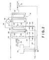
- FIG. 2 is a schematic view showing the construction of a heat recovery steam generator according to an embodiment of the present invention
- FIG. 3 is a schematic view showing the arrangement of burners in a first-stage auxiliary combustor provided in the heat recovery steam generator of FIG. 2 ;
- FIG. 4 is a schematic view showing the arrangement of burners in a second-stage auxiliary combustor provided in the heat recovery steam generator of FIG. 2 ;
- FIG. 5 is a graph showing the relationship between the load of a gas turbine and the degree of opening of an air control valve in the auxiliary combustor of FIG. 4 ;
- FIG. 6 is a graph showing the relationship between the amount of fuel fed and the degree of opening of the air control valve in the auxiliary combustor of FIG. 4 ;
- FIG. 7 is a graph showing the relationship between the amount of fuel fed and the concentration of carbon monoxide in the auxiliary combustor of FIG. 4 .
- FIG. 1 is a system diagram of a combined cycle power plant in which the heat recovery steam generator of the present invention is applied.
- reference numeral 10 represents a power generator
- 12 represents a steam turbine
- 14 represents a gas turbine
- Reference numeral 16 represents a heat recovery steam generator.
- the power generator 10 is coupled to the steam turbine 12 and the gas turbine 14 by the same drive shaft 18 . Further, an air compressor 20 is coupled to the drive shaft 18 .
- the air compressor 20 compresses air A, which has been taken in from the outside, into a high-temperature and high-pressure state and supplies the compressed air to a combustor 22 .
- a fuel that has been supplied from a fuel system 24 is mixed with compressed air and burns, and the high-temperature, high-pressure combustion gas is fed to the gas turbine 14 . Expansion work performed by the combustion gas rotationally drives the gas turbine 14 , thereby rotating the power generator 10 .
- An exhaust gas 25 discharged from the gas turbine 14 , is passed through an exhaust duct 26 and introduced into the heat recovery steam generator 16 .
- a high-temperature superheater 28 in the duct 27 of the heat recovery steam generator 16 are provided four types of heat exchangers, a high-temperature superheater 28 , a low-temperature superheater 30 , an evaporator 32 and an economizer 34 , which are disposed in this order in the flow direction of the exhaust gas 25 discharged from the gas turbine 14 , with the superheater 28 being located most upstream.
- the evaporator 32 is provided with a steam drum 36 .
- the economizer 34 heats boiler feed water with the heat of the exhaust gas 25 , and supplies the heated water to the steam drum 36 .
- saturated steam generated in the evaporator 32 is subjected to gas-liquid separation, and the surface of water is kept at a predetermined level in order to balance with the saturated steam. Water which has undergone the gas-liquid separation in the steam drum 36 is re-introduced into the evaporator 32 .
- Saturated steam in the steam drum 36 is fed through a saturated steam pipe 38 into the low-temperature superheater 30 , where the steam is superheated.
- the heated steam is then introduced into the high-temperature superheater 28 , where the steam is further superheated.
- a temperature reducer 40 for adjusting the temperature of steam is provided between the low-temperature superheater 30 and the high-temperature superheater 28 .
- An outlet pipe 42 is connected to the boiler outlet of the high-temperature superheater 28 .
- the superheated steam that has been superheated in the high-temperature superheater 28 is fed though the outlet pipe 42 to the steam turbine 12 , where the heated steam performs expansion work and rotates the steam turbine 12 .
- the steam after the work is introduced into a steam condenser 43 , where the steam is returned to water.
- the condensed water is then fed through a condensate return pipe 45 into a water feed pump 46 whereby the water is pressured and returned to the economizer 34 .
- auxiliary combustors 50 , 52 are provided as follows:
- the first-stage auxiliary combustor 50 is disposed most upstream in the flow direction of the exhaust gas 25 and, in the case of the heat recovery steam generator 16 of this embodiment, is disposed upstream of the high-temperature superheater 28 .
- the first-stage auxiliary combustor 50 has a plurality of burners 51 directed toward the downstream high-temperature superheater 28 .
- the first fuel supply pipe 54 is provided with a fuel control valve 56 and a fuel shutoff valve 57 .
- the amount of fuel, to be fed into the burners 51 is controlled by adjusting the degree of opening of the fuel control valve 56 .
- the fuel shutoff valve 57 is closed when extinguishing all the burners 51 .
- FIG. 3 is a diagram showing the arrangement of the burners 51 in the first-stage auxiliary combustor 50 and also showing fuel supply pipes to the respective burners 51 .
- the first fuel supply pipe 54 branches out into fuel supply pipes 58 a, 58 b downstream of the fuel control valve 56 and, in this embodiment, the fuel supply pipes 58 a , 58 b are each connected to four burners 51 in parallel via fuel shutoff valves 59 .
- Each burner 51 can be extinguished individually by closing the corresponding fuel shutoff valve 59 .
- the second-stage auxiliary combustor 52 is disposed downstream of the first-stage auxiliary combustor 50 and, in this embodiment, upstream of the evaporator 32 .
- the second-stage auxiliary combustor 52 has a plurality of burners 53 directed toward the downstream evaporator 32 .
- the second fuel supply pipe 55 is provided with a fuel control valve 60 for controlling the amount of fuel to be fed to the burners 53 , and a fuel shutoff valve 61 which is closed when extinguishing all the burners 53 .
- FIG. 4 is a diagram showing the arrangement of the burners 53 in the second-stage auxiliary combustor 52 and also showing fuel supply pipes and air ducts to the respective burners 53 .
- the second fuel supply pipe 55 branches out into fuel supply pipes 63 a , 63 b downstream of the fuel control valve 60 and, in this embodiment, the fuel supply pipes 63 a , 63 b are each connected to four burners 53 in parallel via fuel shutoff valves 64 .
- Each burner 53 can be extinguished individually by closing the corresponding shutoff valve 64 .
- An air control valve 68 is provided at an air inlet in each burner 53 .
- the degree of opening of the air control valve 68 can be adjusted by means of an actuator 69 .
- reference numeral 70 represents a controller for controlling operations to light/extinguish the first-stage auxiliary combustor 50 and the second-stage auxiliary combustor 52 and also controlling the amount of air to be supplied to the auxiliary combustors 50 , 52 .
- the flow rate of fuel flowing in the fuel system 24 is detected by a flow meter 62 and inputted into the controller 70 .
- a gas sensor 72 for detecting the concentration of a harmful gas, such as carbon monoxide or nitrogen oxide, in the exhaust gas is provided in an exhaust duct for introducing the exhaust gas, discharged from the heat recovery steam generator 16 , into a smokestack.
- a gas concentration detection signal from the gas sensor 72 is introduced into the controller 70 .
- the second-stage auxiliary combustor 52 is disposed upstream of the evaporator 32 .
- the amount of evaporation in the evaporator 32 can be increased.
- the first-stage auxiliary combustor 50 is disposed upstream of the high-temperature superheater 28 and the low-temperature superheater 30 .
- the degree of superheat of steam in each of the high-temperature superheater 28 and the low-temperature superheater 30 can be increased.
- the burners 53 of the second-stage auxiliary combustor 52 are lit first and the amount of fuel fed to the second-stage auxiliary combustor 52 is increased. If the first-stage auxiliary combustor 50 is operated from the start, the high-temperature superheater 28 and the low-temperature superheater 30 , which are insufficient in the amount of evaporation, may be too superheated by the high-temperature exhaust gas 25 .
- the fuel is supplied also to the first-stage auxiliary combustor 50 to burn the fuel in the burners 51 .
- the temperature of the exhaust gas 25 is raised by heating it by means of the first-stage auxiliary combustor 50 , superheating of steam in the high-temperature superheater 28 and the low-temperature superheater 30 can be insufficient, resulting in a too low steam temperature at the boiler outlet of the high-temperature superheater 28 .
- the fan 65 is rotated to cause air to flow through the air ducts 66 a , 66 b and to be supplied to the burners 53 , as shown in FIG. 4 , so that unstable combustion due to a shortage of oxygen will not occur in the second-stage auxiliary combustor 52 .
- Oxygen can thus be additionally supplied to the burners 53 of the second-stage auxiliary combustor 52 .
- This makes it possible to ensure a stable combustion state in the second-stage auxiliary combustor 52 , thereby preventing emission of a harmful gas, such as carbon monoxide, from the second-stage auxiliary combustor 52 .
- the combustion state in the second-stage auxiliary combustor 52 will not be stable if the amount of air supplied by the fan 65 is too large or too small. An appropriate amount of air is therefore supplied to each burner 53 while adjusting the degree of opening of each air control valve 68 .
- the controller 70 instructs the corresponding actuator 69 on the intended degree of opening of the air valve 68 .
- the controller 70 automatically controls the degree of opening of each air control valve 68 to maintain the optimal combustion state while monitoring the concentration of a harmful gas, such as carbon monoxide, emitted from the second-stage auxiliary combustor 52 based on an output signal from the gas sensor 72 .
- the load of the gas turbine 14 and the amount of the fuel fed, in addition to the amount of air supplied affect the combustion state in the auxiliary combustor 52 .
- the combustion state in the second-stage auxiliary combustor 52 will be considerably unstable and an increased amount of carbon monoxide, etc. will be emitted when the gas turbine 14 is operated at high load and a small amount of fuel is fed into the second-stage auxiliary combustor 52 .
- FIG. 5 is a graph showing the relationship between the load of the gas turbine 14 and the degree of opening of the air control valve 68 .
- the flow rate of the exhaust gas 25 supplied from the gas turbine 14 to the heat recovery steam generator 16 , is low when the gas turbine 14 is operated in a low-load range, and therefore the degree of opening of the air control valve 68 is set to be full open as shown in FIG. 5 .
- the flow rate of the exhaust gas 25 increases with increase in the load of the gas turbine 14 .
- the controller 70 gradually decreases the degree of opening of the air control valve 68 so that air will not be supplied in an excessive amount to each burner 53 of the second-stage auxiliary combustor 52 .
- the optimal opening degree in relation to the load of the gas turbine 14 is preset so that the concentration of a harmful gas, such as carbon monoxide, in the gas emitted from the second-stage auxiliary combustor 52 will not exceed a limit value; the opening degree may be decreased linearly as shown in FIG. 5 .
- the degree of opening of the air control valve 68 is thus decreased with increase in the load of the gas turbine 14 . This makes it possible to supply an optimal amount of air to each burner 53 of the second-stage auxiliary combustor 52 , thereby maintaining a stable combustion state.
- FIG. 6 is a graph showing the relationship between the amount of fuel fed to the second-stage auxiliary combustor 52 and the degree of opening of the air control valve 68 .
- an appropriate degree of opening of the air control valve 68 is preset in a low-fuel feed range in order to stabilize combustion in each burner 53 .
- the amount of air necessary for combustion increases with increase in the amount of fuel fed to the second-stage auxiliary combustor 52 .
- the controller 70 while monitoring the fuel feed with the flow meter 62 , increases the amount of air supplied to each burner 53 by increasing the degree of opening of the air control valve 68 after a preset fuel feed F 1 is reached.
- the amount of fuel fed to the second-stage auxiliary combustor 52 may need to be decreased so that the amount of steam generated will not exceed an upper limit value.
- the combustion state in each burner 53 is likely to become unstable and, in some cases, the concentration of a harmful gas, such as carbon monoxide, can become extremely high. In such a case, some of the burners 53 are extinguished so that the concentration of a harmful gas, such as carbon monoxide, will not exceed a predetermined limit value, as show in FIG. 7 .
- the abscissa represents the amount of fuel fed to the second-stage auxiliary combustor 52 and the ordinate represents the concentration of carbon monoxide in a gas emitted from the second-stage auxiliary combustor 52 .
- the “Cmax” represents the limit value for the concentration of carbon monoxide.
- the curve A shows change in the concentration of carbon monoxide when all the burners 53 of the second-stage auxiliary combustor 52 are lit.
- the concentration of carbon monoxide increases with decrease in the fuel feed.
- the controller 70 based on an output signal from the gas sensor 72 , monitors the concentration of carbon monoxide emitted from the second-stage auxiliary combustor 52 and, when the concentration of carbon monoxide has come close to the limit value Cmax, closes the fuel shutoff valves 64 of e.g. half, i.e. four in the illustrated case, of the burners 53 to extinguish the burners.
- some of the burners 53 of the second-stage auxiliary combustor 52 may be extinguished to stabilize the combustion state in the remaining lighting burners 53 .
- the heat recovery steam generator of the present invention can also be applied in a plant which supplies steam not only to a steam turbine but also to e.g. a water desalination plant.
Applications Claiming Priority (3)
| Application Number | Priority Date | Filing Date | Title |
|---|---|---|---|
| JP2011-122420 | 2011-05-31 | ||
| JP2011122420A JP5774381B2 (ja) | 2011-05-31 | 2011-05-31 | 排熱回収ボイラおよび発電プラント |
| PCT/JP2012/064233 WO2012165601A1 (ja) | 2011-05-31 | 2012-05-31 | 排熱回収ボイラおよび発電プラント |
Related Parent Applications (1)
| Application Number | Title | Priority Date | Filing Date |
|---|---|---|---|
| PCT/JP2012/064233 Continuation WO2012165601A1 (ja) | 2011-05-31 | 2012-05-31 | 排熱回収ボイラおよび発電プラント |
Publications (2)
| Publication Number | Publication Date |
|---|---|
| US20140090356A1 US20140090356A1 (en) | 2014-04-03 |
| US9416686B2 true US9416686B2 (en) | 2016-08-16 |
Family
ID=47259452
Family Applications (1)
| Application Number | Title | Priority Date | Filing Date |
|---|---|---|---|
| US14/090,813 Active 2033-06-13 US9416686B2 (en) | 2011-05-31 | 2013-11-26 | Heat recovery steam generator and power plant |
Country Status (5)
| Country | Link |
|---|---|
| US (1) | US9416686B2 (ko) |
| JP (1) | JP5774381B2 (ko) |
| KR (1) | KR101530807B1 (ko) |
| DE (1) | DE112012002336T5 (ko) |
| WO (1) | WO2012165601A1 (ko) |
Families Citing this family (11)
| Publication number | Priority date | Publication date | Assignee | Title |
|---|---|---|---|---|
| ES2535513T3 (es) * | 2011-09-07 | 2015-05-12 | Alstom Technology Ltd | Método para el funcionamiento de una central eléctrica |
| CN103256644B (zh) * | 2013-04-11 | 2015-07-08 | 杭州锅炉集团股份有限公司 | 扩大低压省煤器系统 |
| US9260982B2 (en) * | 2013-05-30 | 2016-02-16 | General Electric Company | System and method of waste heat recovery |
| US9587520B2 (en) * | 2013-05-30 | 2017-03-07 | General Electric Company | System and method of waste heat recovery |
| EP3001102B1 (en) | 2014-09-26 | 2020-10-28 | Stork Thermeq B.V. | A heat recovery unit and power plant |
| CN107075976B (zh) | 2014-10-24 | 2020-03-31 | 西门子公司 | 用于提高管道燃烧的联合循环发电设备的响应性的系统和方法 |
| DK3037635T3 (da) * | 2014-12-22 | 2017-11-20 | Alfa Laval Corp Ab | System og fremgangsmåde til behandling af udstødningsgas såvel som skib, der omfatter et sådant system, og anvendelse heraf |
| KR102132044B1 (ko) * | 2015-06-16 | 2020-07-09 | 현대중공업파워시스템 주식회사 | 복합 화력발전 시스템 |
| DE102017223705A1 (de) * | 2017-12-22 | 2019-06-27 | E.On Energy Projects Gmbh | Kraftwerk |
| JP7414663B2 (ja) * | 2020-08-06 | 2024-01-16 | 株式会社東芝 | 排熱回収ボイラ |
| CN112010522A (zh) * | 2020-09-13 | 2020-12-01 | 上海康恒环境股份有限公司 | 一种垃圾焚烧锅炉耦合污泥低温炭化处置系统 |
Citations (15)
| Publication number | Priority date | Publication date | Assignee | Title |
|---|---|---|---|---|
| US3443550A (en) * | 1967-05-05 | 1969-05-13 | Gen Electric | Two-section heat recovery steam generator |
| US4555902A (en) * | 1984-01-16 | 1985-12-03 | Vevy Manufacturing Inc. | Heat recovery system |
| JPH04313601A (ja) | 1991-04-11 | 1992-11-05 | Ishikawajima Harima Heavy Ind Co Ltd | ボイラ設備 |
| GB2277965A (en) * | 1993-05-12 | 1994-11-16 | British Gas Plc | Steam turbine |
| JPH0729583A (ja) | 1993-07-12 | 1995-01-31 | Ishikawajima Harima Heavy Ind Co Ltd | 燃料電池発電装置 |
| US5558047A (en) * | 1994-11-30 | 1996-09-24 | The Babcock & Wilcox Company | Low Nox integrated boiler-burner cogeneration apparatus |
| US5628183A (en) * | 1994-10-12 | 1997-05-13 | Rice; Ivan G. | Split stream boiler for combined cycle power plants |
| US5632143A (en) * | 1994-06-14 | 1997-05-27 | Ormat Industries Ltd. | Gas turbine system and method using temperature control of the exhaust gas entering the heat recovery cycle by mixing with ambient air |
| JPH1037716A (ja) | 1996-07-26 | 1998-02-10 | Ishikawajima Harima Heavy Ind Co Ltd | 排気再燃型コンバインドサイクルプラントの空気流量制御方法及び装置 |
| US6141956A (en) * | 1997-08-29 | 2000-11-07 | Mitsubishi Heavy Industries, Inc. | Combined power generation plant |
| JP2001116208A (ja) | 1999-10-14 | 2001-04-27 | Babcock Hitachi Kk | ダクトバーナ付き排熱回収ボイラ |
| US6298655B1 (en) * | 1999-05-25 | 2001-10-09 | Korea Heavy Industries & Construction Co., Ltd. | Air supply duct for heat recovery steam generators |
| US6557499B2 (en) * | 1998-06-10 | 2003-05-06 | Siemens Aktiengesellschaft | Fossil-fuel-fired once-through steam generator |
| JP2007232262A (ja) | 2006-02-28 | 2007-09-13 | Hitachi Ltd | コージェネレーションプラント及びその運転方法 |
| US20100305768A1 (en) * | 2009-06-01 | 2010-12-02 | General Electric Company | Control for improved thermal performance of a steam turbine at partial load |
-
2011
- 2011-05-31 JP JP2011122420A patent/JP5774381B2/ja active Active
-
2012
- 2012-05-31 WO PCT/JP2012/064233 patent/WO2012165601A1/ja active Application Filing
- 2012-05-31 DE DE112012002336.6T patent/DE112012002336T5/de active Pending
- 2012-05-31 KR KR1020137032291A patent/KR101530807B1/ko active IP Right Grant
-
2013
- 2013-11-26 US US14/090,813 patent/US9416686B2/en active Active
Patent Citations (15)
| Publication number | Priority date | Publication date | Assignee | Title |
|---|---|---|---|---|
| US3443550A (en) * | 1967-05-05 | 1969-05-13 | Gen Electric | Two-section heat recovery steam generator |
| US4555902A (en) * | 1984-01-16 | 1985-12-03 | Vevy Manufacturing Inc. | Heat recovery system |
| JPH04313601A (ja) | 1991-04-11 | 1992-11-05 | Ishikawajima Harima Heavy Ind Co Ltd | ボイラ設備 |
| GB2277965A (en) * | 1993-05-12 | 1994-11-16 | British Gas Plc | Steam turbine |
| JPH0729583A (ja) | 1993-07-12 | 1995-01-31 | Ishikawajima Harima Heavy Ind Co Ltd | 燃料電池発電装置 |
| US5632143A (en) * | 1994-06-14 | 1997-05-27 | Ormat Industries Ltd. | Gas turbine system and method using temperature control of the exhaust gas entering the heat recovery cycle by mixing with ambient air |
| US5628183A (en) * | 1994-10-12 | 1997-05-13 | Rice; Ivan G. | Split stream boiler for combined cycle power plants |
| US5558047A (en) * | 1994-11-30 | 1996-09-24 | The Babcock & Wilcox Company | Low Nox integrated boiler-burner cogeneration apparatus |
| JPH1037716A (ja) | 1996-07-26 | 1998-02-10 | Ishikawajima Harima Heavy Ind Co Ltd | 排気再燃型コンバインドサイクルプラントの空気流量制御方法及び装置 |
| US6141956A (en) * | 1997-08-29 | 2000-11-07 | Mitsubishi Heavy Industries, Inc. | Combined power generation plant |
| US6557499B2 (en) * | 1998-06-10 | 2003-05-06 | Siemens Aktiengesellschaft | Fossil-fuel-fired once-through steam generator |
| US6298655B1 (en) * | 1999-05-25 | 2001-10-09 | Korea Heavy Industries & Construction Co., Ltd. | Air supply duct for heat recovery steam generators |
| JP2001116208A (ja) | 1999-10-14 | 2001-04-27 | Babcock Hitachi Kk | ダクトバーナ付き排熱回収ボイラ |
| JP2007232262A (ja) | 2006-02-28 | 2007-09-13 | Hitachi Ltd | コージェネレーションプラント及びその運転方法 |
| US20100305768A1 (en) * | 2009-06-01 | 2010-12-02 | General Electric Company | Control for improved thermal performance of a steam turbine at partial load |
Non-Patent Citations (1)
| Title |
|---|
| International Search Report issued on Aug. 28, 2013 for PCT/JP2012/064233 filed on May 31, 2012 with English Translation. |
Also Published As
| Publication number | Publication date |
|---|---|
| WO2012165601A1 (ja) | 2012-12-06 |
| DE112012002336T5 (de) | 2014-02-20 |
| KR20140040737A (ko) | 2014-04-03 |
| KR101530807B1 (ko) | 2015-06-22 |
| JP5774381B2 (ja) | 2015-09-09 |
| JP2012251671A (ja) | 2012-12-20 |
| US20140090356A1 (en) | 2014-04-03 |
Similar Documents
| Publication | Publication Date | Title |
|---|---|---|
| US9416686B2 (en) | Heat recovery steam generator and power plant | |
| US8393138B2 (en) | Oxygen-enriched air assisting system for improving the efficiency of cogeneration system | |
| US20140150438A1 (en) | System and method for operating a gas turbine in a turndown mode | |
| EP2959128B1 (en) | Gas turbine with fuel composition control | |
| RU2013116441A (ru) | Энергоустановка, включающая контур рециркуляции | |
| US9528396B2 (en) | Heat recovery steam generator and power plant | |
| JP2010261456A (ja) | ガスタービン用燃料を加熱するシステム及び方法 | |
| CN113874603B (zh) | 用于改进锅炉和蒸汽涡轮机启动时间的系统和方法 | |
| JP5400850B2 (ja) | 排熱ボイラシステムの制御方法および制御装置 | |
| JPH0933005A (ja) | 排熱回収ボイラ給水装置 | |
| JP2007285553A (ja) | 燃焼ボイラの制御方法 | |
| US10344627B2 (en) | Heat recovery steam generator and power plant | |
| KR102485928B1 (ko) | 하이브리드 발전설비의 급기장치 및 급기방법 | |
| US20220136437A1 (en) | Air supplying apparatus and method of hybrid power generation equipment | |
| JP6357701B1 (ja) | 燃焼状態判定システム | |
| JP2007024425A (ja) | 複合ボイラシステム及びその運転方法 | |
| JP2005147136A (ja) | ガスタービンの燃料制御装置 | |
| JPH01189404A (ja) | ドラム水位制御装置 |
Legal Events
| Date | Code | Title | Description |
|---|---|---|---|
| AS | Assignment |
Owner name: KABUSHIKI KAISHA TOSHIBA, JAPAN Free format text: ASSIGNMENT OF ASSIGNORS INTEREST;ASSIGNORS:NAKAMURA, KEIICHI;SHIMADA, HIDEAKI;SIGNING DATES FROM 20140115 TO 20140116;REEL/FRAME:032052/0843 |
|
| STCF | Information on status: patent grant |
Free format text: PATENTED CASE |
|
| MAFP | Maintenance fee payment |
Free format text: PAYMENT OF MAINTENANCE FEE, 4TH YEAR, LARGE ENTITY (ORIGINAL EVENT CODE: M1551); ENTITY STATUS OF PATENT OWNER: LARGE ENTITY Year of fee payment: 4 |
|
| MAFP | Maintenance fee payment |
Free format text: PAYMENT OF MAINTENANCE FEE, 8TH YEAR, LARGE ENTITY (ORIGINAL EVENT CODE: M1552); ENTITY STATUS OF PATENT OWNER: LARGE ENTITY Year of fee payment: 8 |