US9413628B2 - Network relay node device, network relay method, and recording medium - Google Patents
Network relay node device, network relay method, and recording medium Download PDFInfo
- Publication number
- US9413628B2 US9413628B2 US13/625,196 US201213625196A US9413628B2 US 9413628 B2 US9413628 B2 US 9413628B2 US 201213625196 A US201213625196 A US 201213625196A US 9413628 B2 US9413628 B2 US 9413628B2
- Authority
- US
- United States
- Prior art keywords
- network
- node device
- relay node
- information
- connection port
- Prior art date
- Legal status (The legal status is an assumption and is not a legal conclusion. Google has not performed a legal analysis and makes no representation as to the accuracy of the status listed.)
- Expired - Fee Related, expires
Links
Images




Classifications
-
- H—ELECTRICITY
- H04—ELECTRIC COMMUNICATION TECHNIQUE
- H04L—TRANSMISSION OF DIGITAL INFORMATION, e.g. TELEGRAPHIC COMMUNICATION
- H04L43/00—Arrangements for monitoring or testing data switching networks
- H04L43/10—Active monitoring, e.g. heartbeat, ping or trace-route
-
- H—ELECTRICITY
- H04—ELECTRIC COMMUNICATION TECHNIQUE
- H04L—TRANSMISSION OF DIGITAL INFORMATION, e.g. TELEGRAPHIC COMMUNICATION
- H04L12/00—Data switching networks
- H04L12/02—Details
- H04L12/16—Arrangements for providing special services to substations
- H04L12/18—Arrangements for providing special services to substations for broadcast or conference, e.g. multicast
- H04L12/1886—Arrangements for providing special services to substations for broadcast or conference, e.g. multicast with traffic restrictions for efficiency improvement, e.g. involving subnets or subdomains
-
- H—ELECTRICITY
- H04—ELECTRIC COMMUNICATION TECHNIQUE
- H04L—TRANSMISSION OF DIGITAL INFORMATION, e.g. TELEGRAPHIC COMMUNICATION
- H04L12/00—Data switching networks
- H04L12/28—Data switching networks characterised by path configuration, e.g. LAN [Local Area Networks] or WAN [Wide Area Networks]
- H04L12/46—Interconnection of networks
- H04L12/4604—LAN interconnection over a backbone network, e.g. Internet, Frame Relay
- H04L12/462—LAN interconnection over a bridge based backbone
-
- H—ELECTRICITY
- H04—ELECTRIC COMMUNICATION TECHNIQUE
- H04L—TRANSMISSION OF DIGITAL INFORMATION, e.g. TELEGRAPHIC COMMUNICATION
- H04L12/00—Data switching networks
- H04L12/28—Data switching networks characterised by path configuration, e.g. LAN [Local Area Networks] or WAN [Wide Area Networks]
- H04L12/46—Interconnection of networks
- H04L12/4604—LAN interconnection over a backbone network, e.g. Internet, Frame Relay
- H04L12/462—LAN interconnection over a bridge based backbone
- H04L12/4625—Single bridge functionality, e.g. connection of two networks over a single bridge
-
- H—ELECTRICITY
- H04—ELECTRIC COMMUNICATION TECHNIQUE
- H04L—TRANSMISSION OF DIGITAL INFORMATION, e.g. TELEGRAPHIC COMMUNICATION
- H04L45/00—Routing or path finding of packets in data switching networks
- H04L45/18—Loop-free operations
Definitions
- the embodiments discussed herein are related to a network relay node technique for relaying communication between a first network and a second network having a communication protocol different from the communication protocol of the first network.
- the first network is a network, for example, an ad hoc network for connection of communication units directly or through another communication unit by cable or by wireless without using a network connection device such as a router, an access point, a base station, etc.
- a network connection device such as a router, an access point, a base station, etc.
- the second network having a protocol different from the protocol of the first network is a network, for example, a LAN (local area network) for collecting various types of information from a node as a terminal configuring, for example, an ad hoc network.
- a network connection device for example, a network connection device.
- a switch in a LAN is connected to a network relay node as a communication unit in an ad hoc network, and is connected to a server computer as a communication unit in a LAN (hereafter simply referred to as a “server”). Then, the server in the LAN controls each node in the ad hoc network or collects information from each node.
- a server for collecting the sensor information in the LAN collects various types of sensor information from a node in an ad hoc network operating as sensor equipment.
- the broadcast information transmitted from a server 1 in the LAN is received by a switch SW.
- the SW After recognizing the broadcast information, the SW transmits the broadcast information to the node B in the connected ad hoc network.
- the node B After receiving the broadcast information, the node B transmits the broadcast information to all ports connected to the local node, for example, to the node A and other nodes.
- each node configuring the network has a mesh-shaped connection configuration. Therefore, a route is physically looped.
- the communication information is looped, normal routing is not performed.
- a system in which the communication information passing through the route is not looped although the route is physically looped is incorporated into the first network.
- a network relay node device for relay from a first network to a second network having a protocol different from a protocol of the first network through a switch includes: an identical segment information generation control unit for generating identical segment information for identification of another relay node device belonging to a same segment as a local device in the second network; and a loop suppression control unit for suppressing a loop of a communication including the switch by broadcasting a received broadcast frame only to a connection port of the first network if the identical segment information is detected in identification source node information acquired from a header of the broadcast frame when the broadcast frame is received from a connection port of the first network.
- FIG. 1 is a configuration of a certain network
- FIG. 2 is an explanatory view ( 1 ) of the problem with the duplex connection
- FIG. 3 is an explanatory view ( 2 ) of the problem with the duplex connection
- FIG. 4 is an example of a configuration of the network system according to the embodiment.
- FIG. 5 is an explanatory view of the STP system
- FIG. 6 is a configuration of the connection port of a node
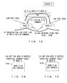
- FIGS. 7A, 7B, and 7C are explanatory views of an entering operation on the identical segment table according to the embodiment.
- FIG. 8 is an example of a configuration of data of a “LAN side link-up notification” command
- FIG. 9 is an example of a configuration of data of a Ping request command and reply
- FIG. 10 is an explanatory view of a process of inputting a broadcast frame according to the embodiment.
- FIG. 11 is a configuration of the hardware of a node
- FIG. 12 is a block diagram of the function of a node
- FIGS. 13A and 13B are flowcharts of the entering, updating, and deleting processes of the identical segment table
- FIG. 14 is a practical example of the network system according to the embodiment.
- FIG. 15 is a configuration of hardware capable of realizing the embodiment.
- connection between the server etc. in the second network and the node in the first network may need to be duplex.
- FIG. 2 there is a configuration illustrated in FIG. 2 .
- a server 1 and a server 2 are connected to a switch SW in a LAN, and a node A and a node B in an ad hoc network are connected to the switch SW. That is, in FIG. 2 , the server on the LAN side is duplexed, and the node on the ad hoc network side is duplexed.
- An ARP Address Resolution Protocol
- An ARP request is broadcast information.
- the ARP request is further transmitted to a port other than the reception port connected to the local device.
- each device notifies the transmitter of the ARP request of the MAC address of the local device.
- the server 1 normally acquires the MAC address, and performs a communication with the server 2 using the MAC address of the server 2 .
- the SW Upon receipt of the ARP request, the SW transmits the ARP request to all ports other than the port which has received the ARP request (S 2 in FIG. 2 ).
- the ARP requests are received by the nodes A and B. Since the ARP requests are not addressed to the nodes A and B, the ARP requests are further transmitted to all ports of the SW other than the ports of the SW which have received the ARP requests (S 3 in FIG. 2 ).
- the ARP request transmitted by the SW to the node A may be returned to the SW through the node B, thereby generating a loop.
- the network connection device and the server of the SW in the second network the network goes down if a loop is generated in the network, and a communication is not correctly established. Therefore, the server 1 does not receive a reply to the ARP request from the server 2 , and is not informed of the MAC address of the server 2 .
- An aspect of the embodiments aim at realizing a duplex configuration for suppressing a loop with a high degree of freedom and with a load of a network designer reduced in connecting the first network such as an ad hoc network etc. to the second network such as a LAN etc.
- FIG. 4 is a network system according to an embodiment of the present invention.
- An ad hoc network 401 configures the first network in which nodes as communication units are interconnected directly or through another node.
- a LAN (Local Area Network) 402 configures the second network in which, for example, the servers 1 and 2 as communication units are interconnected through a switch SW as a network connection device.
- the switch SW interconnects the nodes A and B as relay nodes which operate as gateways for collecting the information about all nodes in the ad hoc network 401 to the servers 1 and 2 in the LAN 402 . That is, the nodes A and B on the ad hoc network 401 side are duplexed and the servers 1 and 2 on the LAN 402 side are also duplexed.
- FIG. 5 is an explanatory view of the STP system.
- a loop state of the communication information is detected by transmitting special data called a BPDU (Bridge Protocol Data Unit).
- BPDU Binary Protocol Data Unit
- a specific route for example, a route 501 is set as a constant route, and other routes, for example, a route 502 is cut off so that it is not to be used normally, and defined as a bypass in case a fault occurs.
- the nodes A and B are duplexed, and a loop of information communications is suppressed even when there is a physical loop among the switch SW and the nodes A and B.
- the servers 1 and 2 do not communicate with each node in the ad hoc network in a normal operation only through the route 501 using the node A. That is, the server 1 or 2 does not directly communicate with the node B. Therefore, in the normal operation, the duplex configuration in which, for example, the server 1 directly communicates with the node A or B, and simultaneously the server 2 directly communicates with the node A or B is not realized.
- FIG. 6 is a configuration of the connection port of a node 601 corresponding to each relay node of the ad hoc network 401 illustrated in FIG. 4 according to the present embodiment.
- the node 601 includes a LAN port 602 for connection to the switch SW illustrated in FIG. 4 , and a plurality of (for example, four) trunk ports 603 for connection to a plurality of nodes in the ad hoc network 401 .
- FIGS. 7A through 7C are explanatory views of the entering operation of the identical segment table according to the present embodiment.
- the nodes A and B ( FIG. 4 ) respectively form identical segment tables 701 A and 701 B indicating the nodes A and B belong to the identical segment as illustrated in FIGS. 7B and 7C .
- Belonging to the identical segment refers to a connection under the condition that a broadcast frame transmitted in the second network can be received.
- a LAN port 602 A of the node A is in a non-link-up state
- a LAN port 602 B of the node B is in a linked-up state.
- the non-link-up state refers to a state in which the LAN port 602 A has not yet been opened in a communication enabled state.
- the node A When the LAN port 602 A links up, the node A broadcasts a LAN side link up notification command from a trunk port 603 A of the node A to the trunk port of another node (step S 1 in FIG. 7A ). According to the command, the node B is informed of the IP address of the LAN port 602 A of the node A, and that the LAN port 602 A of the node A has linked up.
- the node B upon receipt of the LAN side link up notification command from any trunk port 603 B, the node B issues an echo request packet, for example, a Ping request command from the LAN port 602 B to the node A through the switch SW (step S 2 in FIG. 7A ).
- the Ping request command from the node B is received by the node A which has transmitted the LAN side link up notification command through the connected route.
- the node B receives an echo reply packet, for example, a Ping reply command from the node A (step S 4 ), and confirms that Ping has received by the node A, thereby recognizing that the nodes A and B are connected between the LAN ports 602 A and 602 B.
- the node A when the node A first transmits the LAN side link up notification command, and receives the Ping request command from the node B (step S 2 in FIG. 7A ), it writes the ad hoc address of the node B as illustrated in FIG. 7B to the identical segment table 701 A of the local node (step S 3 a ).
- the node A returns a Ping reply from the LAN port to the node B (step S 4 in FIG. 7A ).
- the node B Upon receipt of the Ping reply from the node A through the LAN port (step S 4 in FIG. 7A )), the node B is informed that the node A exists in the identical segment.
- the node B writes the ad hoc address of the node A to the identical segment table 701 B of the local node as illustrated in FIG. 7C (step S 3 b ).
- the information is protected from being looped when the broadcast information is input.
- FIG. 8 is an example of a data configuration in which the LAN side link up notification command is an ad hoc command.
- a GD (global destination) field refers to a destination node ID on the ad hoc network 401 ( FIG. 4 ) side.
- the value of the GD field is Oxfffff.
- a GS (global source) field refers to a source node ID of the ad hoc network 401 .
- a Type field refers to a data type. In this field, a value corresponding to the LAN side link up notification.
- a FID field refers to a frame identification ID. In this field, a sequential number is added to each frame.
- a TTL field refers to a frame retention time.
- a Length field refers to a frame length of a Body field portion.
- a FCS field refers to a frame check sequence for error correction of the ad hoc header (from the GD field to the Length) portion.
- a Body field refers to an IP address of the local node (the node A in this example).
- FIG. 9 is an example of a data configuration of the Ping request command and the Ping reply command as a reply of the request command.
- the Ping request command and the reply to the request is realized as an ICMP (Internet Control Message Protocol) message.
- the TYPE field refers to the type of an ICMP message. In this field, a value indicating Ping is set.
- a code field refers to a Ping request command or a Ping reply.
- a checksum field is a field for an error check.
- An inherent header refers to a header inherent to each type of ICMP.
- An ICMP message field is variable length, and indicates the ad hoc address of the local node (the node B in this example) in the present embodiment.
- the ICMP header configured by the above-mentioned TYPE, code, checksum, and inherent header fields, and the ICMP message field configures an ICMP frame for a Ping request command.
- An IP header, a MAC header, and a Body potion (data and FCS) are further added to the ICMP frame, thereby configuring a transmission data.
- IP address As a destination IP address to be added to the IP header, an IP address of the node whose LAN port has been linked up is set. The IP address is acquired from the Body field of the received LAN side link up notification command.
- the ad hoc address of the node B is acquired from the ICMP message field of the received Ping request command.
- the ad hoc address of the node A is acquired from the ICMP message field of the received Ping reply.
- a data configuration example of the Ping reply is similar to that illustrated in FIG. 9 , a value indicating the Ping reply is set in the command field, and the ad hoc address of the node A is set in the ICMP message field.
- a broadcast frame is transmitted from the server 2 , and reaches the node B through the switch SW (step S 5 in FIG. 10 ).
- the broadcast frame also reaches the node A through the SW, the following operation is the same between both nodes. Therefore, only the node B is explained here.
- the node B adds an ad hoc header 1001 to a MAC frame 1002 as a broadcast frame received from the LAN port, and transmits it from each trunk port 603 (displayed by simplifying the trunk port 603 in FIG. 6 ).
- the frame reaches each node, for example, one trunk port of the node A (step S 6 in FIG. 10 ).
- Each node for example, the node A recognizes a broadcast frame in a frame received from any trunk port.
- the data configuration of the ad hoc header of the frame is similar to a data configuration example of the LAN side link up notification command illustrated in FIG. 8 . That is, the GD field refers to a destination node ID. In the broadcast frame, the value of 0xffffff is set. By recognizing the setting, the broadcast frame is recognized.
- the GS field refers to a source node ID. If the received frame is a broadcast frame received from the node B, the ID of the node B is added to the field. Therefore, the node A is informed of the ad hoc address of the node B.
- each node for example, the node A has recognized that the broadcast frame has been received by one trunk port, then the identical segment table 701 A held by the local node is searched using the source node ID acquired from the received frame. As a result, if a hit is acquired by the search, each node does not transmit a received frame to the LAN port 602 , but broadcasts it only to each trunk port 603 other than the receiving trunk port (step S 7 in FIG. 10 ). In the case of node A, the ad hoc address of the source node B is hit. Thus, the node A does not transmit the received broadcast frame to the LAN port 602 , but transmits it only to each trunk port 603 . Thus, the loop of the broadcast frame is suppressed.
- the broadcast frame from the server 2 is broadcast to the node A through the node B, but the loop from the node A to the node B through the switch SW is suppressed. Therefore, according to the embodiment of the present invention illustrated in FIG. 10 , with the configuration in which the nodes A and B are multiplexed, the loop of the information is suppressed although there is a physical loop through the nodes A and B and the switch. Each node does not perform the process of searching the above-mentioned identical segment table for the frame received from the LAN port.
- the process of maintaining the latest information about the identical segment table is performed.
- any node broadcasts the LAN side link disconnection notification command to each trunk port when the LAN port disconnects its link, and completely clears the information in its identical segment table.
- the data configuration example of the LAN side link disconnection notification command is similar to that of the LAN side link up notification illustrated in FIG. 8 .
- the value corresponding to the LAN side link disconnection notification is set in the TYPE field. From the value of the GS field of the command, other nodes are informed of the ad hoc address of the node in which the link disconnection of the LAN port has occurred. The other nodes delete the ad hoc address of the node from the identical segment table held by each of them.
- the LAN side link up notification command transmitted by the operation is periodically transmitted not only during the activation of each node.
- the transmission interval of the command is varied by a setting.
- the second controlling process immediately after the LAN port linkup, the following controlling process is performed. That is, immediately after the linkup of the LAN port, there is the timing with which the communication of the Ping request command or the preparation of the identical segment table has not been performed. In this case, if the broadcast information is received or transmitted, a loop occurs. To avoid this, according to the present embodiment, for example, a guard period of several hundreds mS (millisecond) is set after detecting the linkup of the LAN port, and no broadcast information entering from the LAN port of another node is accepted in the period. The guard period is varied by a setting.
- mS millisecond
- the technique disclosed according to the present embodiment is not limited to the case above, but the operation is performed as in the case above although two or more nodes are connected to the switch SW on the LAN 402 side. That is, for example, on the segment table of the node A, the ad hoc addresses of the plurality of nodes are stored, and the loop to the plurality of nodes is suppressed.
- the server 1 is connected to the node A through the switch SW, and the server 2 is connected to the node B through the switch SW.
- the loop of the information is avoided although there is a looped physical communication path of the switch SW and the nodes A and B. Therefore, according to the present embodiment, when the servers 1 and 2 and/or the nodes A and B are multiplexed, a load distribution is performed between the nodes A and B.
- the server 1 collects information from, for example, a network through the node A, and the server 2 controls an ad hoc network through the node B. Therefore, the function distribution is performed between the servers 1 and 2 or the nodes A and B.
- Each relay node in an ad hoc network holds an identical segment table.
- the relay node includes a port for the second network such as a LAN etc. in addition to the port for the first network for an ad hoc network etc., and has the capability of relaying the information between the first and second networks.
- the relay node in the ad hoc network broadcasts the LAN side linkup notification command storing the IP address of the local node to each trunk port of the local node when the LAN port of the local node links up, or periodically after the linkup.
- the relay node in the ad hoc network Upon receipt of the LAN side link up notification command, the relay node in the ad hoc network transmits a Ping request command storing the ad hoc address of the local node to the LAN port of the local node at the IP address stored in the command. Then, it monitors the Ping reply corresponding to the Ping request command on the LAN port side. Upon receipt of the Ping reply, it enters (or overwrites) the ad hoc address stored in the commanding the identical segment table stored in the local node.
- the relay node in the ad hoc network Upon receipt of a Ping request command from the LAN port, the relay node in the ad hoc network enters (or overwrites) the ad hoc address storing the command in the identical segment table held in the local node. Then, it transmits the Ping reply storing the ad hoc address of the local node to the LAN port of the local node at the source IP address stored in the received Ping request command.
- the relay node in the ad hoc network broadcasts the LAN side link disconnection notification command storing the IP address of the local node to each trunk port of the local node, and completely clears its identical segment table.
- the relay node in the ad hoc network Upon receipt of the LAN side link disconnection notification command, the relay node in the ad hoc network deletes the source ad hoc address of the command from the identical segment table held by the local node.
- the relay node in the ad hoc network adds the ad hoc header to the broadcast frame extracted from the LAN port, and transmits the frame from each trunk port.
- Each relay node recognizes the broadcast frame from the destination node ID in the frequency received from any trunk port. Upon recognition of the broadcast frame, each relay node searches the identical segment table held by the local node using the source node ID which is acquired from the received frame. As a result, when the search makes a hit, each relay node does not transmit the received frame to the LAN port, but broadcasts it only to each trunk port.
- a user of the network having the configuration of the first network such as an ad hoc network etc. connected to the second network such as a LAN etc. uses a connection configuration of a high degree of freedom without considering the loop of the communication information even using a duplexed relay network portion.
- the STP function With the STP function, a connection is made from the switch SW to only one node A (or node B). Therefore, for example, when a different instruction is issued to each node in the ad hoc network 401 from each of the servers 1 and 2 in the LAN 402 , the communication load is concentrated on one node A (or node B) if there is only one node available, thereby restricting the amount of data to be processed.
- the ad hoc network 401 is a sensor network
- the network size is limited if there is only one node to communicate with the LAN 402 .
- the nodes A and B simultaneously communicate with the servers 1 and 2 . Therefore, the load is distributed.
- the servers 1 and 2 when the servers 1 and 2 perform the process having a different purpose, the servers 1 and 2 are not simultaneously connected to the two nodes A and B, thereby restricting the function of the system. According to the present embodiment, the function of a multiplexed server and a multiplexed node is distributed.
- the route switching time is very short when a fault occurs.
- the present embodiment suppresses the communication loop of the information even when there is a physical loop among the nodes A and B and the switch SW in the relay network portion including the duplexed relay nodes A and B in the first network and the switch of the second network having a protocol different from that of the first network.
- the effects a, b, and d work on the technique having the STP function illustrated in FIG. 5 .
- the effect c above works in addition to the effects a, b, and d above on the technique of the STP function.
- FIG. 11 is a configuration of the hardware of the node 601 in FIG. 6 according to the present embodiment.
- FIG. 12 is a block diagram of the function of the node 601 .
- the corresponding portions in FIG. 11 are assigned the identical reference numerals.
- a cable ad hoc port 1106 corresponds to the trunk port 603 in FIG. 6 , and inputs and outputs the communication information communicated with other nodes.
- the cable ad hoc port 1106 is terminated by a PHY (PHYsical Layer Device) 1104 including PHY 1 through 4 for encoding or decoding a transmission/reception frame.
- the portion configured by the cable ad hoc port 1106 and the PHY 1104 is functionally configured by a reception unit 1208 and a transmission unit 1209 as illustrated in FIG. 12 .
- Each of reception ports 1208 - 1 through 1208 - x of the reception unit 1208 performs a decoding operation etc. for each cable ad hoc port 1106 .
- Each of transmission ports 1209 - 1 through 1209 - x of the transmission unit 1209 performs an encoding operation etc. for each cable ad hoc port 1106 .
- the transmission information is provided for each of the transmission ports 1209 - 1 through 1209 - x through a buffer unit 1210 implemented in SDRAM (Synchronous Dynamic Random Access Memory) 1110 .
- SDRAM Serial Dynamic Random Access Memory
- the frame data output and input to and from the PHY 1104 is connected to a FPGA (Field Programmable Gate Array) 1101 through the connection line of an MII (media independent interface) 1117 .
- a general-purpose LAN port 1107 corresponds to the LAN port 602 illustrated in FIG. 6 , and is terminated by an L2SW (layer 2 switch) 1103 .
- each transmission/reception port in the PHY 1104 is monitored by a port monitor unit 1202 in the FPGA 1101 .
- a reception frame control unit 1203 in the FPGA 1101 performs the process of receiving the frame data received by each of the reception ports 1208 - 1 through 1208 - x in the PHY 1104 .
- the frame data received by the reception frame control unit 1203 is passed to an MPU (Micro Processing Unit) 1102 through the connection line of an MII 1114 .
- the data is processed by an upper layer processing unit 1211 configured by the MPU 1102 and DDR2-SDRAM (Double-Data-Rate 2 Synchronous Dynamic Random Access Memory) 1111 controlled thereby, or flash memory (FLASH) 1112 .
- DDR2-SDRAM Double-Data-Rate 2 Synchronous Dynamic Random Access Memory
- a port selection unit 1205 in the FPGA 1101 selects a transmitting port for the frame data received by the reception frame control unit 1203 , and passes the data to a transmission frame control unit 1204 .
- a port selection unit 1205 selects the transmitting port based on the contents of each routing table etc. in a table storage unit 1201 controlled by a table control unit 1206 .
- the table storage unit 1201 also functions as a storage unit for storing an identical segment table as identical segment information.
- the transmission frame control unit 1204 outputs and transmits the frame data received from the port selection unit 1205 to the transmission port specified by the port selection unit 1205 through the buffer unit 1210 .
- the table control unit 1206 enters, updates, and deletes various types of information on each routing table in the table storage unit 1201 or the identical segment table according to the present embodiment based on the transmission/reception state of the reception frame control unit 1203 and the transmission frame control unit 1204 .
- the table control unit 1206 updates and deletes data on each routing table etc. in the table storage unit 1201 based on the timing state of a timer 1207 .
- the table storage unit 1201 is configured by CAM (content Addressable Memory) 1108 and SRAM (Static Random Access Memory) 1109 and SRAM (Static Random Access Memory) 1109 .
- CAM content Addressable Memory
- SRAM Static Random Access Memory
- SRAM Static Random Access Memory
- SRAM Static Random Access Memory
- the transmission frame control unit 1204 issues a transmit instruction to the L2SW 1103 through the MII 1116 in FIG. 11 when the frame data is to be transmitted to the general-purpose LAN port 1107 .
- the frame data received by the L2SW 1103 from the general-purpose LAN port 1107 is received by the reception frame control unit 1203 in the FPGA 1101 from the MII 1116 , or after decoded by a PHY 1105 , it is received by the upper layer processing unit 1211 through an MII 1115 .
- FIGS. 13A and 13B are operation flowcharts of the entering, updating, and deleting processes of the identical segment table.
- the operation flowcharts are realized as, for example, the function of the table control unit 1206 in the FPGA 1101 illustrated in FIG. 12 .
- steps S 1301 through S 1303 relate to the process of transmitting a LAN side link up notification command.
- the state of the general-purpose LAN port 1107 is checked (step S 1301 ). If the general-purpose LAN port 1107 is in the link disconnection state, the determining process is repeatedly performed. The determining process is the process of the table control unit 1206 determining the monitor result of the port monitor unit 1202 .
- the table control unit 1206 in FIG. 12 controls the port selection unit 1205 in the guard period of, for example, several hundreds mS as described above as the second controlling process to stay in the wait state so that the broadcast information received from the general-purpose LAN port 1107 of another node is not accepted (step S 1302 ).
- step S 1303 the table control unit 1206 in FIG. 12 controlling the port selection unit 1205 .
- the LAN side link up notification command is broadcast to each transmission port of the cable ad hoc port 1106 (step S 1303 ).
- steps S 1304 through S 1306 refer to the processes processed after transmitting the LAN side link up notification command.
- the table control unit 1206 issues an inquiry to the reception frame control unit 1203 to determine whether or not a Ping request command addressed to the local node has been received from the general-purpose LAN port 1107 through the L2SW 1103 (step S 1304 ).
- step S 1304 determines whether the determination in step S 1304 is NO. If the determination in step S 1304 is NO, control is passed to step S 1307 .
- step S 1304 If the Ping request command is received, and the determination in step S 1304 is YES, the table control unit 1206 writes the ad hoc address of the node stored in the Ping request command to the identical segment table stored in the table storage unit 1201 (step S 1305 ). Thus, a part of the above-mentioned controlling process as S 2 in FIG. 7A is realized.
- the table control unit 1206 controls the port selection unit 1205 to return a Ping reply from the L2SW 1103 through the general-purpose LAN port 1107 (step S 1306 ).
- the table control unit 1206 sets the value indicating the Ping reply in the command field, and sets the ad hoc address of the local node in the ICMP message field ( FIG. 9 ).
- S 3 in FIG. 7A a part of the above-mentioned controlling process is realized as S 3 in FIG. 7A .
- steps S 1307 through S 1310 are the process of receiving the LAN side link up notification command.
- the table control unit 1206 issues an inquiry to the reception frame control unit 1203 to determine whether or not the LAN side link up notification command has been received from the cable ad hoc port 1106 through the reception unit 1208 (step S 1307 ).
- step S 1307 If the determination in step S 1307 is NO, control is passed to step S 1311 .
- step S 1307 determines whether the LAN side link up notification command is received and the determination in step S 1307 is YES.
- the table control unit 1206 controls the port selection unit 1205 , and transmits a Ping request command from the L2SW 1103 through the general-purpose LAN port 1107 (step S 1308 ).
- the table control unit 1206 sets the value indicating the Ping request in the command field, and sets the ad hoc address of the local node in the ICMP message field ( FIG. 9 ).
- the IP address acquired from the Body field of the LAN side linkup notification command is set.
- the IP address relates to the linkup originating node.
- the table control unit 1206 issues an inquiry to the reception frame control unit 1203 to determine for a specified period whether or not the Ping reply addressed to the local node has been received from the general-purpose LAN port 1107 through the L2SW 1103 (step S 1309 ).
- the identical segment table is not operated in response to the LAN side link up notification command, but control is returned to step S 1304 .
- step S 1309 In response to the Ping reply, and if the determination in step S 1309 is YES, the table control unit 1206 writes the ad hoc address of the node stored in the Ping reply to the identical segment table in the table storage unit 1201 (step S 1310 ). Thus, apart of the above-mentioned controlling process is realized as S 3 in FIG. 7A . Afterwards, control is returned to step S 1304 .
- steps S 1311 and S 1312 are a receiving process of a LAN side link disconnection notification command.
- the table control unit 1206 issues an inquiry to the reception frame control unit 1203 to determine whether or not the LAN side link disconnection notification command has been received from the cable ad hoc port 1106 through the reception unit 1208 (step S 1311 ).
- step S 1311 If the determination in step S 1311 is NO, control is passed to step S 1313 .
- step S 1311 If the LAN side link disconnection notification command is received and the determination in step S 1311 is YES, then the table control unit 1206 deletes the ad hoc address of the link disconnection originating node from the identical segment table held in the table storage unit 1201 (step S 1312 ). The address is acquired from the GS field of the LAN side link disconnection notification command. Afterwards, control is returned to step S 1304 .
- steps S 1313 through S 1315 are a transmitting process for the LAN side link disconnection notification command.
- step S 1313 the state of the general-purpose LAN port 1107 is checked.
- the determining process is performed by the table control unit 1206 to determine a monitor result of the port monitor unit 1202 .
- control is passed to step S 1316 .
- the table control unit 1206 completely clears the contents of the identical segment table in the table storage unit 1201 (step S 1314 ).
- the table control unit 1206 in FIG. 12 controls the port selection unit 1205 to broadcast the LAN side link disconnection notification command to each transmission port of the cable ad hoc port 1106 (step S 1315 ).
- the process in step S 1316 is a process of periodically reporting the LAN side link up notification command.
- the process similar to the process in step S 1303 is performed. That is, by the table control unit 1206 in FIG. 12 controlling the port selection unit 1205 , the LAN side link up notification command is broadcast to each transmission port of the cable ad hoc port 1106 .
- FIG. 14 is an example of a practical configuration of the network system according to the present embodiment.
- a switch 1406 in a relay network 1403 is connected to nodes 1407 A and 1407 B as relay nodes to be the gateway in an ad hoc network 1401 .
- servers 1404 - 1 and 1404 - 2 etc. are connected to the switch 1405 etc.
- the node 1407 A collects data from another node group 1408 A in the ad hoc network 1401 , and transmits the data to the servers 1404 - 1 and 1404 - 2 through the switches 1406 and 1405 etc.
- the node 1407 B collects data from another node group 1408 B in the ad hoc network 1401 , and transmits the data to the servers 1404 - 1 and 1404 - 2 through the switches 1406 and 1405 .
- the duplex configuration of the servers 1404 - 1 and 1404 - 2 and the switches 1407 A and 1407 B is realized.
- the table storage unit 1201 in FIG. 12 functions as a storage unit for storing the identical segment information as an identical segment table.
- the node 601 for performing the operation in S 7 in FIG. 10 and the table control unit 1206 in FIG. 12 function as a loop suppressing unit.
- the node 601 for performing the operation in S 1 in FIG. 7A and the table control unit 1206 in FIG. 12 for performing the processes in step S 1301 through S 1303 in FIG. 13A function as a linkup notification unit.
- the node 601 for performing the operations in S 2 and S 3 in FIG. 7A and the table control unit 1206 in FIG. 12 for performing the processes in steps S 1307 through S 1310 , and S 1304 through S 1306 in FIG. 13A function as an attainment confirmation unit and an identical segment generation and update unit.
- the table control unit 1206 in FIG. 12 for performing the processes in steps S 1311 through S 1315 in FIG. 13B functions as a link disconnection control unit.
- FIG. 15 is an example of a hardware configuration of the computer capable of realizing the above-mentioned system as a software process.
- the computer illustrated in FIG. 15 includes a CPU 1501 , memory 1502 , an input/output device 1503 , an external storage device 1505 , a portable recording medium drive device 1506 into which a portable recording medium 1509 is inserted, and a communication interface 1507 , and these components are interconnected through a 1508 .
- the configuration illustrated in FIG. 15 is an example of a computer capable of realizing the above-mentioned system, and the computer is not limited to the configuration.
- the CPU 1501 performs the entire control of the computer.
- the memory 1502 is memory such as RAM etc. for temporarily storing a program or data stored in the external storage device 1505 or the portable recording medium 1509 when the program is executed, the data is updated, etc.
- the CPU 1501 performs the entire control by reading the program to the memory 1502 and executing the program.
- the input/output device 1503 detects the inputting operation by a user using a keyboard, a mouse, etc., notifies the CPU 1501 of the detection result, and outputs the data transmitted by the control of the CPU 1501 to a display device and a printer device.
- the external storage device 1505 is, for example, a hard disk storage device, and is mainly used in storing various types of data and programs.
- the portable recording medium drive device 1506 accommodates the portable recording medium 1509 such as an optical disk, SDRAM, CompactFlash, etc., and functions as an auxiliary to the external storage device 1505 .
- the communication interface 1507 is to connect a communication circuit of, for example, a LAN (Local Area Network), or a WAN (Wide Area Network).
- a communication circuit of, for example, a LAN (Local Area Network), or a WAN (Wide Area Network).
- the system according to the present embodiment is realized by the CPU 1501 executing the program provided with the function realized as illustrated according to the flowchart illustrated in FIGS. 13A and 13B .
- the program is recorded on the external storage device 1505 and the portable recording medium 1509 and distributed, or acquired from a network through the communication interface 1507 .
- a duplex configuration at a high degree of freedom is realized by suppressing a loop of a relay network portion including the first network connected to the second network having a protocol different from that of the first network with a reduced load of a network designer.
Landscapes
- Engineering & Computer Science (AREA)
- Computer Networks & Wireless Communication (AREA)
- Signal Processing (AREA)
- Health & Medical Sciences (AREA)
- Cardiology (AREA)
- General Health & Medical Sciences (AREA)
- Small-Scale Networks (AREA)
- Data Exchanges In Wide-Area Networks (AREA)
Applications Claiming Priority (1)
| Application Number | Priority Date | Filing Date | Title |
|---|---|---|---|
| PCT/JP2010/002397 WO2011121673A1 (ja) | 2010-03-31 | 2010-03-31 | ネットワーク中継ノード装置、ネットワーク中継方法、プログラム、およびネットワークシステム |
Related Parent Applications (1)
| Application Number | Title | Priority Date | Filing Date |
|---|---|---|---|
| PCT/JP2010/002397 Continuation WO2011121673A1 (ja) | 2010-03-31 | 2010-03-31 | ネットワーク中継ノード装置、ネットワーク中継方法、プログラム、およびネットワークシステム |
Publications (2)
| Publication Number | Publication Date |
|---|---|
| US20130016627A1 US20130016627A1 (en) | 2013-01-17 |
| US9413628B2 true US9413628B2 (en) | 2016-08-09 |
Family
ID=44711470
Family Applications (1)
| Application Number | Title | Priority Date | Filing Date |
|---|---|---|---|
| US13/625,196 Expired - Fee Related US9413628B2 (en) | 2010-03-31 | 2012-09-24 | Network relay node device, network relay method, and recording medium |
Country Status (3)
| Country | Link |
|---|---|
| US (1) | US9413628B2 (ja) |
| JP (1) | JP5445671B2 (ja) |
| WO (1) | WO2011121673A1 (ja) |
Cited By (1)
| Publication number | Priority date | Publication date | Assignee | Title |
|---|---|---|---|---|
| US20230261898A1 (en) * | 2020-10-19 | 2023-08-17 | Nissan Motor Co., Ltd. | Relay device, communication network system, and communication control method |
Families Citing this family (12)
| Publication number | Priority date | Publication date | Assignee | Title |
|---|---|---|---|---|
| US8750122B1 (en) * | 2012-03-22 | 2014-06-10 | Avaya, Inc. | Method and apparatus for layer 2 loop prevention in a multi-node switch cluster |
| JP5838380B2 (ja) * | 2013-03-28 | 2016-01-06 | パナソニックIpマネジメント株式会社 | 通信システム、携帯型情報端末、通信アダプタ、及び通信方法 |
| KR20150026257A (ko) * | 2013-09-02 | 2015-03-11 | 삼성전자주식회사 | 액세서리의 정보를 업 데이트하는 전자 장치 및 방법 |
| JP6388434B2 (ja) * | 2014-07-18 | 2018-09-12 | アライドテレシスホールディングス株式会社 | ネットワーク機器、通信方法、プログラム、記録媒体 |
| JP6388436B2 (ja) * | 2014-08-29 | 2018-09-12 | アライドテレシスホールディングス株式会社 | ネットワーク機器、通信方法、プログラム、記録媒体 |
| US9723168B2 (en) * | 2015-03-19 | 2017-08-01 | Ricoh Company, Ltd. | Information processing apparatus, information processing system, and computer program product |
| US10255180B2 (en) * | 2015-12-11 | 2019-04-09 | Netapp, Inc. | Server-based persistence management in user space |
| JP6445985B2 (ja) * | 2016-02-05 | 2018-12-26 | 日本電信電話株式会社 | 振分システム、振分装置、及び振分方法 |
| US10409632B2 (en) * | 2017-03-31 | 2019-09-10 | The Boeing Company | Emulation of hardware components based on interrupt design |
| JP7109903B2 (ja) * | 2017-11-02 | 2022-08-01 | キヤノン株式会社 | 情報処理装置及びその制御方法、並びにプログラム |
| CN113055295B (zh) * | 2018-08-01 | 2024-11-19 | 华为技术有限公司 | 通信方法、通信设备和通信系统 |
| JP7010804B2 (ja) * | 2018-11-22 | 2022-01-26 | 株式会社東芝 | 中継装置、ネットワークシステム、中継方法およびプログラム |
Citations (7)
| Publication number | Priority date | Publication date | Assignee | Title |
|---|---|---|---|---|
| US20040167988A1 (en) * | 2002-12-23 | 2004-08-26 | Johan Rune | Bridging between a Bluetooth scatternet and an Ethernet LAN |
| JP2005130049A (ja) | 2003-10-21 | 2005-05-19 | Fujitsu Ltd | ノード |
| JP2006279168A (ja) | 2005-03-28 | 2006-10-12 | Kddi Corp | アドホック網を構成する通信装置、ブリッジ装置及び通信システム |
| US20060265480A1 (en) * | 2005-05-18 | 2006-11-23 | Samsung Electronics Co., Ltd. | Method of transmitting and receiving data in network environment with wired and wireless networks bridged using relay portal |
| JP2007243288A (ja) | 2006-03-06 | 2007-09-20 | Nec Corp | 通信システム、ノード、通信方法、およびノード用プログラム |
| US20080049764A1 (en) * | 2006-08-22 | 2008-02-28 | Corrigent Systems Ltd. | Point-to-multipoint functionality in a bridged network |
| US20080112422A1 (en) * | 2005-07-21 | 2008-05-15 | Jorjeta Jetcheva | Method for Enabling the Efficient Operation of Arbitrarily Interconnected Mesh Networks |
-
2010
- 2010-03-31 JP JP2012507916A patent/JP5445671B2/ja not_active Expired - Fee Related
- 2010-03-31 WO PCT/JP2010/002397 patent/WO2011121673A1/ja not_active Ceased
-
2012
- 2012-09-24 US US13/625,196 patent/US9413628B2/en not_active Expired - Fee Related
Patent Citations (7)
| Publication number | Priority date | Publication date | Assignee | Title |
|---|---|---|---|---|
| US20040167988A1 (en) * | 2002-12-23 | 2004-08-26 | Johan Rune | Bridging between a Bluetooth scatternet and an Ethernet LAN |
| JP2005130049A (ja) | 2003-10-21 | 2005-05-19 | Fujitsu Ltd | ノード |
| JP2006279168A (ja) | 2005-03-28 | 2006-10-12 | Kddi Corp | アドホック網を構成する通信装置、ブリッジ装置及び通信システム |
| US20060265480A1 (en) * | 2005-05-18 | 2006-11-23 | Samsung Electronics Co., Ltd. | Method of transmitting and receiving data in network environment with wired and wireless networks bridged using relay portal |
| US20080112422A1 (en) * | 2005-07-21 | 2008-05-15 | Jorjeta Jetcheva | Method for Enabling the Efficient Operation of Arbitrarily Interconnected Mesh Networks |
| JP2007243288A (ja) | 2006-03-06 | 2007-09-20 | Nec Corp | 通信システム、ノード、通信方法、およびノード用プログラム |
| US20080049764A1 (en) * | 2006-08-22 | 2008-02-28 | Corrigent Systems Ltd. | Point-to-multipoint functionality in a bridged network |
Non-Patent Citations (4)
| Title |
|---|
| International Search Report mailed Jun. 22, 2010 issued in corresponding International Patent Application No. PCT/JP2010/002397. |
| Notification of Transmittal of the International Preliminary Report on Patentability mailed Nov. 1, 2012 in corresponding International Application No. PCT/JP2010/002397. |
| Office Action issued May 28, 2013 in corresponding Japanese Application No. 2012-507916. |
| Sawatte Nattoku! Network Jikkenshitsu, 2002, 9 pages. |
Cited By (2)
| Publication number | Priority date | Publication date | Assignee | Title |
|---|---|---|---|---|
| US20230261898A1 (en) * | 2020-10-19 | 2023-08-17 | Nissan Motor Co., Ltd. | Relay device, communication network system, and communication control method |
| US12101203B2 (en) * | 2020-10-19 | 2024-09-24 | Nissan Motor Co., Ltd. | Relay device, communication network system, and communication control method |
Also Published As
| Publication number | Publication date |
|---|---|
| JP5445671B2 (ja) | 2014-03-19 |
| JPWO2011121673A1 (ja) | 2013-07-04 |
| US20130016627A1 (en) | 2013-01-17 |
| WO2011121673A1 (ja) | 2011-10-06 |
Similar Documents
| Publication | Publication Date | Title |
|---|---|---|
| US9413628B2 (en) | Network relay node device, network relay method, and recording medium | |
| US11134012B2 (en) | Communication system, communication device, controller, and method and program for controlling forwarding path of packet flow | |
| US9608903B2 (en) | Systems and methods for recovery from network changes | |
| US9357471B2 (en) | Node apparatus and alternative path search method | |
| US8672566B2 (en) | Node apparatus and communication method | |
| US10044830B2 (en) | Information system, control apparatus, method of providing virtual network, and program | |
| US9264327B2 (en) | Communication network management system, method and program, and management computer | |
| EP2533475B1 (en) | Method and system for host route reachability in packet transport network access ring | |
| EP2555476A1 (en) | Method, system and device for protecting multicast in communication network | |
| US20130272111A1 (en) | Method and device for link fault detecting and recovering based on arp interaction | |
| CN110247851B (zh) | 三层交换机中的信息更新方法、装置、三层交换机及介质 | |
| US7974188B2 (en) | Repeater and communication method | |
| US20130268801A1 (en) | Server management apparatus, server management method, and program | |
| KR20140072343A (ko) | Sdn 망의 장애 대처 방법 | |
| CN104980355A (zh) | 一种sdn环境下的源端可控组播数据传输方法及系统 | |
| JP5618946B2 (ja) | 通信装置および通信システム | |
| US20150312090A1 (en) | Relay System and Switching Device | |
| CN106302021B (zh) | 一种网络流转发异常检测方法 | |
| US20090006650A1 (en) | Communication device, communication method, communication interface, and program product | |
| US8665754B2 (en) | Path generating method, relay device, and computer product | |
| KR102912343B1 (ko) | 메시지 처리 방법, 디바이스, 네트워크 기기 및 매체 | |
| KR101610031B1 (ko) | 소프트웨어 정의 네트워크에서 컨트롤러를 내장하는 오픈플로우 스위치의 제어방법 및 장치 | |
| JP2013198077A (ja) | ネットワーク及びブリッジ | |
| CN114500273B (zh) | 用于电力载波通信传输的方法、装置、系统 | |
| US8750134B2 (en) | Communication network management system and method and management computer |
Legal Events
| Date | Code | Title | Description |
|---|---|---|---|
| AS | Assignment |
Owner name: FUJITSU LIMITED, JAPAN Free format text: ASSIGNMENT OF ASSIGNORS INTEREST;ASSIGNORS:HIGASHIHARA, YUJI;MAEDA, KENJI;REEL/FRAME:029154/0985 Effective date: 20120921 |
|
| ZAAA | Notice of allowance and fees due |
Free format text: ORIGINAL CODE: NOA |
|
| ZAAB | Notice of allowance mailed |
Free format text: ORIGINAL CODE: MN/=. |
|
| STCF | Information on status: patent grant |
Free format text: PATENTED CASE |
|
| MAFP | Maintenance fee payment |
Free format text: PAYMENT OF MAINTENANCE FEE, 4TH YEAR, LARGE ENTITY (ORIGINAL EVENT CODE: M1551); ENTITY STATUS OF PATENT OWNER: LARGE ENTITY Year of fee payment: 4 |
|
| FEPP | Fee payment procedure |
Free format text: MAINTENANCE FEE REMINDER MAILED (ORIGINAL EVENT CODE: REM.); ENTITY STATUS OF PATENT OWNER: LARGE ENTITY |
|
| LAPS | Lapse for failure to pay maintenance fees |
Free format text: PATENT EXPIRED FOR FAILURE TO PAY MAINTENANCE FEES (ORIGINAL EVENT CODE: EXP.); ENTITY STATUS OF PATENT OWNER: LARGE ENTITY |
|
| STCH | Information on status: patent discontinuation |
Free format text: PATENT EXPIRED DUE TO NONPAYMENT OF MAINTENANCE FEES UNDER 37 CFR 1.362 |
|
| FP | Lapsed due to failure to pay maintenance fee |
Effective date: 20240809 |