US9354135B2 - Oil leak detection device - Google Patents
Oil leak detection device Download PDFInfo
- Publication number
- US9354135B2 US9354135B2 US13/981,447 US201213981447A US9354135B2 US 9354135 B2 US9354135 B2 US 9354135B2 US 201213981447 A US201213981447 A US 201213981447A US 9354135 B2 US9354135 B2 US 9354135B2
- Authority
- US
- United States
- Prior art keywords
- polymer
- oil leak
- line
- film layer
- oil
- Prior art date
- Legal status (The legal status is an assumption and is not a legal conclusion. Google has not performed a legal analysis and makes no representation as to the accuracy of the status listed.)
- Active, expires
Links
- 238000001514 detection method Methods 0.000 title claims abstract description 18
- 229920000642 polymer Polymers 0.000 claims abstract description 61
- 238000010586 diagram Methods 0.000 description 11
- 229920001940 conductive polymer Polymers 0.000 description 8
- 238000000034 method Methods 0.000 description 4
- 239000000853 adhesive Substances 0.000 description 3
- 230000001070 adhesive effect Effects 0.000 description 3
- 238000001179 sorption measurement Methods 0.000 description 3
- XEEYBQQBJWHFJM-UHFFFAOYSA-N Iron Chemical compound [Fe] XEEYBQQBJWHFJM-UHFFFAOYSA-N 0.000 description 2
- 238000006243 chemical reaction Methods 0.000 description 2
- 230000006835 compression Effects 0.000 description 2
- 238000007906 compression Methods 0.000 description 2
- 239000004744 fabric Substances 0.000 description 2
- 230000004927 fusion Effects 0.000 description 2
- 239000007788 liquid Substances 0.000 description 2
- 239000004810 polytetrafluoroethylene Substances 0.000 description 2
- 229920001343 polytetrafluoroethylene Polymers 0.000 description 2
- 229940100890 silver compound Drugs 0.000 description 2
- 150000003379 silver compounds Chemical class 0.000 description 2
- RYGMFSIKBFXOCR-UHFFFAOYSA-N Copper Chemical compound [Cu] RYGMFSIKBFXOCR-UHFFFAOYSA-N 0.000 description 1
- 238000007792 addition Methods 0.000 description 1
- 239000002390 adhesive tape Substances 0.000 description 1
- 229910052802 copper Inorganic materials 0.000 description 1
- 239000010949 copper Substances 0.000 description 1
- 230000000694 effects Effects 0.000 description 1
- 229910052742 iron Inorganic materials 0.000 description 1
- 238000012986 modification Methods 0.000 description 1
- 230000004048 modification Effects 0.000 description 1
- 239000002861 polymer material Substances 0.000 description 1
- -1 stainless Chemical compound 0.000 description 1
- 238000006467 substitution reaction Methods 0.000 description 1
- XLYOFNOQVPJJNP-UHFFFAOYSA-N water Substances O XLYOFNOQVPJJNP-UHFFFAOYSA-N 0.000 description 1
Images


Classifications
-
- G—PHYSICS
- G01—MEASURING; TESTING
- G01M—TESTING STATIC OR DYNAMIC BALANCE OF MACHINES OR STRUCTURES; TESTING OF STRUCTURES OR APPARATUS, NOT OTHERWISE PROVIDED FOR
- G01M3/00—Investigating fluid-tightness of structures
- G01M3/02—Investigating fluid-tightness of structures by using fluid or vacuum
- G01M3/04—Investigating fluid-tightness of structures by using fluid or vacuum by detecting the presence of fluid at the leakage point
- G01M3/16—Investigating fluid-tightness of structures by using fluid or vacuum by detecting the presence of fluid at the leakage point using electric detection means
- G01M3/165—Investigating fluid-tightness of structures by using fluid or vacuum by detecting the presence of fluid at the leakage point using electric detection means by means of cables or similar elongated devices, e.g. tapes
-
- G—PHYSICS
- G01—MEASURING; TESTING
- G01M—TESTING STATIC OR DYNAMIC BALANCE OF MACHINES OR STRUCTURES; TESTING OF STRUCTURES OR APPARATUS, NOT OTHERWISE PROVIDED FOR
- G01M3/00—Investigating fluid-tightness of structures
- G01M3/02—Investigating fluid-tightness of structures by using fluid or vacuum
- G01M3/04—Investigating fluid-tightness of structures by using fluid or vacuum by detecting the presence of fluid at the leakage point
- G01M3/042—Investigating fluid-tightness of structures by using fluid or vacuum by detecting the presence of fluid at the leakage point by using materials which expand, contract, disintegrate, or decompose in contact with a fluid
- G01M3/045—Investigating fluid-tightness of structures by using fluid or vacuum by detecting the presence of fluid at the leakage point by using materials which expand, contract, disintegrate, or decompose in contact with a fluid with electrical detection means
-
- G—PHYSICS
- G01—MEASURING; TESTING
- G01M—TESTING STATIC OR DYNAMIC BALANCE OF MACHINES OR STRUCTURES; TESTING OF STRUCTURES OR APPARATUS, NOT OTHERWISE PROVIDED FOR
- G01M3/00—Investigating fluid-tightness of structures
- G01M3/02—Investigating fluid-tightness of structures by using fluid or vacuum
- G01M3/04—Investigating fluid-tightness of structures by using fluid or vacuum by detecting the presence of fluid at the leakage point
- G01M3/16—Investigating fluid-tightness of structures by using fluid or vacuum by detecting the presence of fluid at the leakage point using electric detection means
- G01M3/18—Investigating fluid-tightness of structures by using fluid or vacuum by detecting the presence of fluid at the leakage point using electric detection means for pipes, cables or tubes; for pipe joints or seals; for valves; for welds; for containers, e.g. radiators
-
- G—PHYSICS
- G01—MEASURING; TESTING
- G01M—TESTING STATIC OR DYNAMIC BALANCE OF MACHINES OR STRUCTURES; TESTING OF STRUCTURES OR APPARATUS, NOT OTHERWISE PROVIDED FOR
- G01M3/00—Investigating fluid-tightness of structures
- G01M3/40—Investigating fluid-tightness of structures by using electric means, e.g. by observing electric discharges
-
- G—PHYSICS
- G01—MEASURING; TESTING
- G01N—INVESTIGATING OR ANALYSING MATERIALS BY DETERMINING THEIR CHEMICAL OR PHYSICAL PROPERTIES
- G01N27/00—Investigating or analysing materials by the use of electric, electrochemical, or magnetic means
Definitions
- the present invention relates to an oil leak detection device and, more particularly, to an oil leak detection device directly attached to an oil pipeline, an oil tank, or a supply pipe, such as the place where oil is expected to leak, in a tape manner and configured to detect leaking oil and determine whether or not oil leaks simply and precisely.
- Leak sensors using various methods for sensing oil leak are being used.
- the applicant of the present invention already proposed an oil leak detection device, such as that shown in FIG. 10 of Korean Patent Application No. 10-2009-0065050.
- a conductive line 42 made of a silver compound or pure conductive ink having 0 to 20 ⁇ is printed on a top surface of a base film layer 41 formed of a film, such as PET, PE, PTFE, or PVC in a length direction.
- a conductive polymer line 43 is attached to the top surface of the base film layer 41 and is spaced apart from the conductive line 42 at a specific interval in parallel to the conductive line 42 .
- the conductive polymer line 43 reacts to oil, such as hydrocarbone liquid, and detects whether or not oil leak has occurred by sensing a change of a resistance value due to the reaction.
- oil such as hydrocarbone liquid
- An upper protection film layer 50 is stacked over the base film layer 41 .
- a plurality of holes 51 is formed in the upper protection film layer 50 at specific intervals in a length direction, and the holes 51 are formed at the same location as the location where the conductive polymer line 43 is attached.
- the volume of the conductive polymer line 43 is increased by the porosity of the conductive polymer line 43 and thus a resistance value is increased.
- a controller determines whether or not oil has leaked by reading a change of a resistance value.
- the conventional oil leak detection device has a high probability that an error can occur because the conductive polymer line 43 for sensing oil leak is very sensitive to a change of temperature.
- the conventional oil leak detection device is problematic in that oil leak is erroneously determined because a resistance value is changed due to an increase in the volume of the conductive polymer line 43 although oil leak is not generated when temperature rises due to a change of surrounding environments.
- an object of the present invention is to provide an oil leak detection device, wherein a pair of polymer lines are formed in parallel on a tape base, only one of the polymer lines detects oil, and the other of the polymer lines functions as a reference line for a change of a resistance value attributable to a change of temperature and precisely detects oil leak irrespective of a change of temperature.
- an oil leak detection device includes a base film layer configured in a tape form, a pair of polymer lines formed on a top surface of the base film layer in parallel in a length direction, a pair of conductive lines formed on the top surface of the base film layer in parallel to the pair of polymer lines in the length direction, and an upper protection film layer attached to the top surface of the base film layer and configured to have a plurality of sensing holes formed at specific intervals in the length direction at locations through which only one of the pair of polymer lines is exposed.
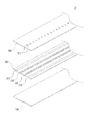
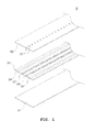
- FIG. 1 is a perspective view of the present invention which is exploded for each layer;
- FIG. 2 is a diagram showing a positional relationship between a polymer line and holes
- FIG. 3 is a diagram showing a state in which a controller and an oil leak detection device are coupled
- FIG. 4 is a block diagram showing an internal circuit of a controller
- FIG. 5 is a graph showing a change in the resistance value of a polymer line attributable to a change of temperature
- FIG. 6 is a diagram showing another embodiment of the present invention to which an oil pipeline is applied;
- FIG. 7 is a diagram showing yet another embodiment of the present invention for detecting oil leak levels
- FIG. 8 is a diagram showing a positional relationship between a polymer line and holes
- FIG. 9 is a diagram illustrating a state in which an oil leak level is detected.
- FIG. 10 is a diagram showing the structure of a conventional oil leak detection device.
- FIG. 1 is a diagram showing the cross section of an oil leak sensor 10 in accordance with an embodiment of the present invention.
- the oil leak sensor 10 is configured in a tape form in such a way as to be attached to a floor, the surface of a wall, or the outside of a pipe.
- the oil leak sensor 10 includes an attachment layer 100 , a base layer 200 , and an upper protection layer 300 which are sequentially stacked from the bottom to the top.
- the attachment layer 100 is attached to a place where oil leak is expected to occur and is formed of an adhesive tape, such a double-sided tape.
- a pair of polymer lines 220 and 230 are attached to the top surface of the base layer 200 and are spaced apart from the conductive lines 210 and 240 at specific intervals in parallel to the conductive lines 210 and 240 .
- the polymer lines 220 and 230 preferably are formed in close proximity, and the conductive lines 210 and 240 are formed outside the polymer lines 220 and 230 .
- first conductive line 210 and the first polymer line 220 are electrically coupled by a connector, and the other ends of the second conductive line 240 and the second polymer line 230 are also electrically coupled likewise.
- the polymer lines 220 and 230 can be made of porous or conductive polymer.
- Each of the polymer lines 220 and 230 reacts to oil, such as hydrocarbone liquid, and detects whether or not oil leak has occurred by sensing a change of a resistance value due to the reaction.
- oil such as hydrocarbone liquid
- a method of attaching the polymer lines 220 and 230 to the base layer 200 can include a variety of methods, such as those using an adhesive, ultrasonic fusion, and thermal compression.
- the polymer lines 220 and 230 can be attached the top surface of the base layer 200 simultaneously with the upper protection layer 300 when the upper protection layer 300 is attached to the top surface of the base layer 200 .
- the upper protection layer 300 is placed over the base layer 200 .
- a plurality of sensing holes 310 is formed in the upper protection layer 300 at specific intervals in a length direction so that only one (e.g., the polymer line 220 ) of the pair of polymer lines 220 and 230 is exposed externally as in FIG. 2 .
- the polymer line 230 not exposed through the sensing holes 310 becomes a reference line for sensing a change of temperature.
- the base layer 200 and the upper protection layer 300 stacked as described above are adhered together using thermal compression, ultrasonic fusion, or an adhesive.
- parts other than the sensing holes 310 , the conductive lines 210 and 240 , and the polymer lines 220 and 230 are adhered, and the attachment layer 100 can be further attached to the bottom of the base layer 200 .
- the oil leak sensor 10 couples the conductive lines 210 and 240 and a signal line 500 through a connector 400 so that the conductive lines 210 and 240 and a signal line 500 are connected to a controller 600 .
- the processor 610 of the controller 600 controls a power source unit 620 so that the power source unit 620 supplies the first conductive line 210 with voltage having several V and determines whether oil leaks or not based on a voltage value from the first polymer line 220 .
- the volume or the amount of adsorption of the first polymer line 220 is increased, so a resistance value in the first polymer line 220 is increased.
- a voltage drop value that may occur depending on the length of the oil leak sensor 10 is previously set in a setting value storage unit 630 because voltage inputted to the processor 610 indispensably drops depending on the length of the oil leak sensor 10 . If a voltage drop value sensed by the first polymer line 220 is higher than the set voltage drop value, the processor 610 determines that oil leaks and outputs an alarm signal through a display unit 640 and an alarm generation unit 650 in order to inform a manager that oil has leaked.
- the first polymer line 220 is made of polymer materials sensitive to temperature and thus sensitive to a change of external temperature. Accordingly, there is a need for a structure for compensating for the frequent error.
- a change of a resistance value attributable to a change of temperature is compensated for using the second polymer line 230 adjacent to the first polymer line 220 as a reference.
- the power source unit 620 supplies voltage of several V to the second conductive line 240
- resistance values of the first polymer line 220 and the second polymer line 230 are identically increased according to a rise of temperature due to the supply of voltage as shown in FIG. 5( a ) .
- the processor 610 determines a change of a resistance value attributable to a change of temperature as a normal operating state not oil leak.
- the processor 610 determines that oil leak has occurred and thus outputs an alarm through the display unit 640 and the alarm generation unit 650 .
- first polymer line 220 and the second polymer line 230 are formed in close proximity to the highest degree so that the same change of temperature is applied to the first polymer line 220 and the second polymer line 230 .
- FIG. 6 is a diagram showing another embodiment of the present invention.
- the oil leak sensor 10 of the present invention is received within a flexible pipe 730 in which a plurality of inlet holes 731 through which oil enters is formed.
- Adsorption fabric 740 is placed within the pipe 730 in which the oil leak sensor 10 is received.
- the pipe 730 is buried under an oil pipeline 750 buried in the ground and configured to sense oil leak generated from the oil pipeline 750 .
- oil is introduced through the inlet holes 731 of the pipe 730 , the oil enters the oil leak sensor 10 through the adsorption fabric 740 and thus oil leak is sensed.
- Both sides of the oil leak sensor 10 are introduced into the manhole 700 and are coupled by neighboring oil leak sensors and the connectors 720 .
- a cover 710 is installed over the manhole 700 in order to open or close the manhole 700 . Accordingly, the oil leak sensor 10 and the connector 720 can be easily coupled.
- FIG. 7 is a diagram showing yet another embodiment of the present invention.
- Polymer lines 721 are diagonally formed on a top surface of a base layer 720 stepwise in a width direction.
- the base layer 720 is formed of a film.
- the polymer lines 721 are coupled by embedded lines 722 having electrical conductivity.
- the polymer line 721 at the lowest is connected to a conductive line 723 and configured to receive sensing power from the controller 600 .
- the polymer line 721 at the highest is also connected to the controller 600 and configured to supply the controller 600 with a voltage value attributable to a change of a resistance value.
- An attachment layer 710 is stacked on a bottom surface of the base layer 720 .
- An upper protection layer 730 is stacked on a top surface of the base layer 720 .
- Sensing holes 731 are formed in the top surface of the base layer 720 so that the polymer lines 721 are externally exposed as in FIG. 8 .
- the controller 600 is informed of a change in the resistance value of the polymer lines 721 at respective locations due to a change of an oil level.
- the polymer lines 721 have the same width and length, and the lower end of one polymer line and the upper end of the other polymer line are placed on the same line. Accordingly, a continuous change of oil levels can be sensed based on a consecutive change of resistance values depending on the height of the polymer lines.
- an oil leak sensor is lengthily installed upright and used as a water-level sensor as in the prior art, it is difficult to sense a continuous change of oil levels because of an interval between the sensing holes.
- the present invention is advantageous in that a consecutive change of oil levels can be sensed.
Landscapes
- Physics & Mathematics (AREA)
- General Physics & Mathematics (AREA)
- Chemical & Material Sciences (AREA)
- Life Sciences & Earth Sciences (AREA)
- Electrochemistry (AREA)
- Health & Medical Sciences (AREA)
- Chemical Kinetics & Catalysis (AREA)
- Analytical Chemistry (AREA)
- Biochemistry (AREA)
- General Health & Medical Sciences (AREA)
- Immunology (AREA)
- Pathology (AREA)
- Examining Or Testing Airtightness (AREA)
- Investigating Or Analyzing Materials By The Use Of Electric Means (AREA)
Applications Claiming Priority (3)
| Application Number | Priority Date | Filing Date | Title |
|---|---|---|---|
| KR10-2011-0078139 | 2011-08-05 | ||
| KR20110078139A KR20130015854A (ko) | 2011-08-05 | 2011-08-05 | 누유 감지 장치 |
| PCT/KR2012/002180 WO2013022165A1 (ko) | 2011-08-05 | 2012-03-26 | 누유 감지 장치 |
Publications (2)
| Publication Number | Publication Date |
|---|---|
| US20130305815A1 US20130305815A1 (en) | 2013-11-21 |
| US9354135B2 true US9354135B2 (en) | 2016-05-31 |
Family
ID=47668651
Family Applications (1)
| Application Number | Title | Priority Date | Filing Date |
|---|---|---|---|
| US13/981,447 Active 2033-01-23 US9354135B2 (en) | 2011-08-05 | 2012-03-26 | Oil leak detection device |
Country Status (6)
| Country | Link |
|---|---|
| US (1) | US9354135B2 (ko) |
| EP (1) | EP2679974A4 (ko) |
| JP (1) | JP5777013B2 (ko) |
| KR (1) | KR20130015854A (ko) |
| CN (1) | CN103328946A (ko) |
| WO (1) | WO2013022165A1 (ko) |
Cited By (1)
| Publication number | Priority date | Publication date | Assignee | Title |
|---|---|---|---|---|
| US20220034743A1 (en) * | 2018-10-16 | 2022-02-03 | 3M Innovative Properties Company | Leak Detector Film |
Families Citing this family (24)
| Publication number | Priority date | Publication date | Assignee | Title |
|---|---|---|---|---|
| CN104412331A (zh) * | 2013-07-02 | 2015-03-11 | 株式会社俞旻St | 漏油感应组成物及利用该组成物的漏油传感器 |
| KR101457393B1 (ko) * | 2013-08-16 | 2014-11-06 | 최기환 | 액상물 감지센서 |
| US9989435B2 (en) * | 2013-11-15 | 2018-06-05 | Eaton Intelligent Power Limited | Electrically conductive polymers as sensing media to detect leaks in aerospace pneumatic ducts |
| KR101447988B1 (ko) * | 2013-11-21 | 2014-10-13 | (주)유민에쓰티 | 방폭 누유 감지장치 |
| CN105987793A (zh) * | 2015-01-28 | 2016-10-05 | 株式会社俞旻St | 强酸性溶液泄漏传感装置 |
| KR101538507B1 (ko) * | 2015-03-26 | 2015-07-23 | 플로우닉스 주식회사 | 측면 검출형 누설 감지 센서 |
| CN105222962A (zh) * | 2015-11-09 | 2016-01-06 | 云南电网有限责任公司红河供电局 | 电力主变压器渗漏油检测贴 |
| CN108010283B (zh) * | 2016-10-31 | 2019-10-29 | 中国石油化工股份有限公司 | 一种油库罐区油品泄漏监测装置 |
| CN106595977A (zh) * | 2016-12-16 | 2017-04-26 | 国家电网公司 | 设备绝缘油泄漏监测报警装置 |
| CN107063580B (zh) * | 2017-01-22 | 2023-11-10 | 柳哲 | 薄膜式有机液体漏液检测系统 |
| CN108569490A (zh) * | 2017-03-08 | 2018-09-25 | 中国人民解放军后勤工程学院 | 油库罐底漏油在线检测装置 |
| KR102067789B1 (ko) * | 2017-10-27 | 2020-01-17 | 해성디에스 주식회사 | 누액 감지 시스템 및 누액 감지 방법 |
| JP6827915B2 (ja) * | 2017-12-18 | 2021-02-10 | タツタ電線株式会社 | 液体検知センサおよび液体検知装置 |
| CN108584200B (zh) * | 2018-07-27 | 2024-08-09 | 青岛澳科仪器有限责任公司 | 一种加油机底盘测漏传感器 |
| CN108773594B (zh) * | 2018-07-27 | 2024-04-16 | 青岛澳科仪器有限责任公司 | 一种油气传感器及其应用的加油机底座、加油机 |
| KR102009968B1 (ko) * | 2018-08-06 | 2019-08-12 | 아머스 주식회사 | 성상분리센서 |
| KR102316047B1 (ko) * | 2019-05-21 | 2021-10-26 | (주)글로벌센서테크 | 리크감지센서 및 이를 포함하는 복합 감지형 리크감지장치 |
| FR3097324B1 (fr) * | 2019-06-12 | 2022-06-10 | M3S Ind | Dispositif de contrôle d’état d’un support et systèmes et procédés associés |
| WO2021010637A1 (ko) * | 2019-07-12 | 2021-01-21 | 주식회사 엔씨티 | 유해화학물질의 감지장치 |
| KR102075773B1 (ko) * | 2019-07-12 | 2020-03-02 | 주식회사 엔씨티 | 유해화학물질의 감지장치. |
| KR102159107B1 (ko) * | 2019-12-16 | 2020-09-24 | 주식회사 엔씨티 | 유해화학물질의 감지장치 |
| KR102075775B1 (ko) * | 2019-07-12 | 2020-03-02 | 주식회사 엔씨티 | 유해화학물질의 감지장치. |
| CN111322525B (zh) * | 2020-04-15 | 2022-02-08 | 湖州市南浔创业测绘与土地规划院股份有限公司 | 一种地下管线探测方法 |
| CN116066762A (zh) * | 2021-11-03 | 2023-05-05 | 台达电子工业股份有限公司 | 泄漏检测感知器及其适用的泄漏检测系统 |
Citations (6)
| Publication number | Priority date | Publication date | Assignee | Title |
|---|---|---|---|---|
| US4677371A (en) * | 1984-10-09 | 1987-06-30 | Junkosha Co., Ltd. | Sensor for detecting the presence and location of a water leak |
| US4801865A (en) * | 1988-01-19 | 1989-01-31 | California Sensor Corporation | Moisture sensor probe with at least two groups of resistive arrays |
| US20070046481A1 (en) * | 2005-09-01 | 2007-03-01 | Vokey David E | Moisture detection sensor tape with leak locate |
| KR100827385B1 (ko) | 2008-01-09 | 2008-05-06 | (주)유민에쓰티 | 물성감지 리크센서 장치 |
| KR20110007501A (ko) | 2009-07-16 | 2011-01-24 | 유홍근 | 누유 감지 장치 |
| KR20110035232A (ko) | 2009-09-30 | 2011-04-06 | (주)유민에쓰티 | 유류탱크의 누유감지장치 |
Family Cites Families (11)
| Publication number | Priority date | Publication date | Assignee | Title |
|---|---|---|---|---|
| JPS55151250A (en) * | 1979-05-15 | 1980-11-25 | Yokohama Rubber Co Ltd:The | Detector for oil or the kind |
| US4404516A (en) * | 1980-10-29 | 1983-09-13 | Johnson Jr Victor R | System for detecting leaks from liquid-containing reservoirs and conduits |
| JPS5880536A (ja) * | 1981-11-09 | 1983-05-14 | Tokyo Tatsuno Co Ltd | 漏れ検知センサの埋設施工方法 |
| JPS58147627A (ja) * | 1982-02-26 | 1983-09-02 | Hitachi Ltd | 流体漏れ検出素子 |
| US5150603A (en) * | 1991-12-13 | 1992-09-29 | Westinghouse Electric Corp. | Hydrocarbon vapor sensor and system |
| JPH06167411A (ja) * | 1992-11-30 | 1994-06-14 | Tatsuta Electric Wire & Cable Co Ltd | 漏液検知線 |
| WO1994028372A1 (en) * | 1993-05-25 | 1994-12-08 | Rosemount Inc. | Organic chemical sensor |
| US6339951B1 (en) * | 1999-07-28 | 2002-01-22 | International Lubrication & Fuel Consultants, Inc. | Leak detection and structural assessment |
| ATE542126T1 (de) * | 2006-04-21 | 2012-02-15 | Daspos As | Ölleckdetektor |
| DE102006053202A1 (de) * | 2006-11-09 | 2008-05-15 | Areva Np Gmbh | Leitungsanordnung zum Transport einer Flüssigkeit, insbesondere Erdöl |
| KR20090065050A (ko) | 2007-12-17 | 2009-06-22 | 김석진 | Mo 서비스를 이용한 상품 구매 시스템 및 그 방법 |
-
2011
- 2011-08-05 KR KR20110078139A patent/KR20130015854A/ko not_active Application Discontinuation
-
2012
- 2012-03-26 CN CN2012800068516A patent/CN103328946A/zh active Pending
- 2012-03-26 JP JP2013554408A patent/JP5777013B2/ja active Active
- 2012-03-26 WO PCT/KR2012/002180 patent/WO2013022165A1/ko active Application Filing
- 2012-03-26 US US13/981,447 patent/US9354135B2/en active Active
- 2012-03-26 EP EP12822009.2A patent/EP2679974A4/en not_active Withdrawn
Patent Citations (7)
| Publication number | Priority date | Publication date | Assignee | Title |
|---|---|---|---|---|
| US4677371A (en) * | 1984-10-09 | 1987-06-30 | Junkosha Co., Ltd. | Sensor for detecting the presence and location of a water leak |
| US4801865A (en) * | 1988-01-19 | 1989-01-31 | California Sensor Corporation | Moisture sensor probe with at least two groups of resistive arrays |
| US20070046481A1 (en) * | 2005-09-01 | 2007-03-01 | Vokey David E | Moisture detection sensor tape with leak locate |
| KR100827385B1 (ko) | 2008-01-09 | 2008-05-06 | (주)유민에쓰티 | 물성감지 리크센서 장치 |
| US20090173143A1 (en) * | 2008-01-09 | 2009-07-09 | Yumin System Technology Co., Ltd. | Leak sensor apparatus for sensing moisture |
| KR20110007501A (ko) | 2009-07-16 | 2011-01-24 | 유홍근 | 누유 감지 장치 |
| KR20110035232A (ko) | 2009-09-30 | 2011-04-06 | (주)유민에쓰티 | 유류탱크의 누유감지장치 |
Cited By (1)
| Publication number | Priority date | Publication date | Assignee | Title |
|---|---|---|---|---|
| US20220034743A1 (en) * | 2018-10-16 | 2022-02-03 | 3M Innovative Properties Company | Leak Detector Film |
Also Published As
| Publication number | Publication date |
|---|---|
| JP5777013B2 (ja) | 2015-09-09 |
| US20130305815A1 (en) | 2013-11-21 |
| EP2679974A1 (en) | 2014-01-01 |
| KR20130015854A (ko) | 2013-02-14 |
| EP2679974A4 (en) | 2015-05-27 |
| JP2014509394A (ja) | 2014-04-17 |
| CN103328946A (zh) | 2013-09-25 |
| WO2013022165A1 (ko) | 2013-02-14 |
Similar Documents
| Publication | Publication Date | Title |
|---|---|---|
| US9354135B2 (en) | Oil leak detection device | |
| KR20110007501A (ko) | 누유 감지 장치 | |
| US20090173143A1 (en) | Leak sensor apparatus for sensing moisture | |
| KR101200918B1 (ko) | 히팅기능을 갖는 리크감지장치 | |
| KR101119823B1 (ko) | 유체관 연결부의 리크감지장치 | |
| JP2009133861A (ja) | 液漏れを検出するセンサ | |
| KR101326923B1 (ko) | 리크 감지 센서 | |
| JP5760027B2 (ja) | 有機液体検出用センター | |
| US6547529B2 (en) | Dry tank shutdown system for pumps | |
| KR102135683B1 (ko) | 누액 감지 센서 및 누액 감지 장치 | |
| JP2010014481A (ja) | 漏水検知装置および漏水検知システム | |
| KR20120128477A (ko) | 방폭지역의 누유감지장치 | |
| WO2010064753A1 (en) | Leakage detection apparatus | |
| KR100859568B1 (ko) | 정전용량형 수위 감지센서 및 시스템 | |
| JP2002107259A (ja) | 埋立地遮水膜の破損位置検知用感知機 | |
| KR101030342B1 (ko) | 정전용량 수위 감지센서 및 시스템 | |
| KR101500515B1 (ko) | 유류저장소의 누유감지장치 | |
| BR112019022524A2 (pt) | Sensor de precisão de profundidade | |
| KR102187189B1 (ko) | 단선 및 리크 검출 장치 및 검출 방법 | |
| KR101695863B1 (ko) | 유체 레벨 센서 | |
| KR200472545Y1 (ko) | 누유 및 수위 감지장치 | |
| KR20180044529A (ko) | 수로형 오일 감지장치 | |
| KR101071071B1 (ko) | 정전용량형 수위 감지시스템 | |
| US11802902B2 (en) | Underwater storage tank, system of assessing the physical integrity of an underwater tank, method for detecting a loss of physical integrity of an underwater storage tank | |
| JP2020079735A (ja) | 特徴量測定装置及びその方法 |
Legal Events
| Date | Code | Title | Description |
|---|---|---|---|
| STCF | Information on status: patent grant |
Free format text: PATENTED CASE |
|
| AS | Assignment |
Owner name: YUMIN SYSTEM TECHNOLOGY CO., LTD., KOREA, REPUBLIC Free format text: ASSIGNMENT OF ASSIGNORS INTEREST;ASSIGNOR:YU, HONG GEUN;REEL/FRAME:046515/0648 Effective date: 20180727 |
|
| MAFP | Maintenance fee payment |
Free format text: PAYMENT OF MAINTENANCE FEE, 4TH YR, SMALL ENTITY (ORIGINAL EVENT CODE: M2551); ENTITY STATUS OF PATENT OWNER: SMALL ENTITY Year of fee payment: 4 |
|
| MAFP | Maintenance fee payment |
Free format text: PAYMENT OF MAINTENANCE FEE, 8TH YR, SMALL ENTITY (ORIGINAL EVENT CODE: M2552); ENTITY STATUS OF PATENT OWNER: SMALL ENTITY Year of fee payment: 8 |