US9327683B2 - Steering apparatus - Google Patents
Steering apparatus Download PDFInfo
- Publication number
- US9327683B2 US9327683B2 US14/066,794 US201314066794A US9327683B2 US 9327683 B2 US9327683 B2 US 9327683B2 US 201314066794 A US201314066794 A US 201314066794A US 9327683 B2 US9327683 B2 US 9327683B2
- Authority
- US
- United States
- Prior art keywords
- lock
- steering
- hole
- lock housing
- outer column
- Prior art date
- Legal status (The legal status is an assumption and is not a legal conclusion. Google has not performed a legal analysis and makes no representation as to the accuracy of the status listed.)
- Active, expires
Links
- 230000002093 peripheral effect Effects 0.000 claims description 50
- 238000003780 insertion Methods 0.000 description 27
- 230000037431 insertion Effects 0.000 description 27
- 230000001965 increasing effect Effects 0.000 description 16
- 238000004512 die casting Methods 0.000 description 11
- 230000007246 mechanism Effects 0.000 description 6
- 229910052751 metal Inorganic materials 0.000 description 6
- 239000002184 metal Substances 0.000 description 6
- 229910001234 light alloy Inorganic materials 0.000 description 5
- 238000003860 storage Methods 0.000 description 5
- 229910000861 Mg alloy Inorganic materials 0.000 description 4
- 238000006073 displacement reaction Methods 0.000 description 4
- 230000000694 effects Effects 0.000 description 4
- 229910000838 Al alloy Inorganic materials 0.000 description 3
- 229910000831 Steel Inorganic materials 0.000 description 3
- 230000015572 biosynthetic process Effects 0.000 description 3
- 230000006872 improvement Effects 0.000 description 3
- 238000004519 manufacturing process Methods 0.000 description 3
- 239000010959 steel Substances 0.000 description 3
- XEEYBQQBJWHFJM-UHFFFAOYSA-N Iron Chemical compound [Fe] XEEYBQQBJWHFJM-UHFFFAOYSA-N 0.000 description 2
- 239000002775 capsule Substances 0.000 description 2
- 230000008859 change Effects 0.000 description 2
- 238000006243 chemical reaction Methods 0.000 description 2
- 238000005336 cracking Methods 0.000 description 2
- 230000007423 decrease Effects 0.000 description 2
- 230000003247 decreasing effect Effects 0.000 description 2
- 230000003534 oscillatory effect Effects 0.000 description 2
- 238000005192 partition Methods 0.000 description 2
- 229910001069 Ti alloy Inorganic materials 0.000 description 1
- 229910001297 Zn alloy Inorganic materials 0.000 description 1
- 238000005452 bending Methods 0.000 description 1
- 238000005266 casting Methods 0.000 description 1
- 230000002708 enhancing effect Effects 0.000 description 1
- 230000007717 exclusion Effects 0.000 description 1
- 230000001771 impaired effect Effects 0.000 description 1
- 238000009434 installation Methods 0.000 description 1
- 229910052742 iron Inorganic materials 0.000 description 1
- 210000003127 knee Anatomy 0.000 description 1
- 239000000463 material Substances 0.000 description 1
- 238000012986 modification Methods 0.000 description 1
- 230000004048 modification Effects 0.000 description 1
- 230000009467 reduction Effects 0.000 description 1
- 230000001105 regulatory effect Effects 0.000 description 1
- 239000011347 resin Substances 0.000 description 1
- 229920005989 resin Polymers 0.000 description 1
- 238000003466 welding Methods 0.000 description 1
Images


Classifications
-
- B—PERFORMING OPERATIONS; TRANSPORTING
- B60—VEHICLES IN GENERAL
- B60R—VEHICLES, VEHICLE FITTINGS, OR VEHICLE PARTS, NOT OTHERWISE PROVIDED FOR
- B60R25/00—Fittings or systems for preventing or indicating unauthorised use or theft of vehicles
- B60R25/01—Fittings or systems for preventing or indicating unauthorised use or theft of vehicles operating on vehicle systems or fittings, e.g. on doors, seats or windscreens
- B60R25/02—Fittings or systems for preventing or indicating unauthorised use or theft of vehicles operating on vehicle systems or fittings, e.g. on doors, seats or windscreens operating on the steering mechanism
- B60R25/021—Fittings or systems for preventing or indicating unauthorised use or theft of vehicles operating on vehicle systems or fittings, e.g. on doors, seats or windscreens operating on the steering mechanism restraining movement of the steering column or steering wheel hub, e.g. restraining means controlled by ignition switch
- B60R25/0211—Fittings or systems for preventing or indicating unauthorised use or theft of vehicles operating on vehicle systems or fittings, e.g. on doors, seats or windscreens operating on the steering mechanism restraining movement of the steering column or steering wheel hub, e.g. restraining means controlled by ignition switch comprising a locking member radially and linearly moved towards the steering column
- B60R25/02115—Fittings or systems for preventing or indicating unauthorised use or theft of vehicles operating on vehicle systems or fittings, e.g. on doors, seats or windscreens operating on the steering mechanism restraining movement of the steering column or steering wheel hub, e.g. restraining means controlled by ignition switch comprising a locking member radially and linearly moved towards the steering column key actuated
- B60R25/02126—Fittings or systems for preventing or indicating unauthorised use or theft of vehicles operating on vehicle systems or fittings, e.g. on doors, seats or windscreens operating on the steering mechanism restraining movement of the steering column or steering wheel hub, e.g. restraining means controlled by ignition switch comprising a locking member radially and linearly moved towards the steering column key actuated with linear bolt motion perpendicular to the lock axis
-
- B—PERFORMING OPERATIONS; TRANSPORTING
- B60—VEHICLES IN GENERAL
- B60R—VEHICLES, VEHICLE FITTINGS, OR VEHICLE PARTS, NOT OTHERWISE PROVIDED FOR
- B60R25/00—Fittings or systems for preventing or indicating unauthorised use or theft of vehicles
- B60R25/01—Fittings or systems for preventing or indicating unauthorised use or theft of vehicles operating on vehicle systems or fittings, e.g. on doors, seats or windscreens
- B60R25/02—Fittings or systems for preventing or indicating unauthorised use or theft of vehicles operating on vehicle systems or fittings, e.g. on doors, seats or windscreens operating on the steering mechanism
- B60R25/021—Fittings or systems for preventing or indicating unauthorised use or theft of vehicles operating on vehicle systems or fittings, e.g. on doors, seats or windscreens operating on the steering mechanism restraining movement of the steering column or steering wheel hub, e.g. restraining means controlled by ignition switch
- B60R25/02105—Arrangement of the steering column thereof
-
- B—PERFORMING OPERATIONS; TRANSPORTING
- B60—VEHICLES IN GENERAL
- B60R—VEHICLES, VEHICLE FITTINGS, OR VEHICLE PARTS, NOT OTHERWISE PROVIDED FOR
- B60R25/00—Fittings or systems for preventing or indicating unauthorised use or theft of vehicles
- B60R25/01—Fittings or systems for preventing or indicating unauthorised use or theft of vehicles operating on vehicle systems or fittings, e.g. on doors, seats or windscreens
- B60R25/02—Fittings or systems for preventing or indicating unauthorised use or theft of vehicles operating on vehicle systems or fittings, e.g. on doors, seats or windscreens operating on the steering mechanism
- B60R25/021—Fittings or systems for preventing or indicating unauthorised use or theft of vehicles operating on vehicle systems or fittings, e.g. on doors, seats or windscreens operating on the steering mechanism restraining movement of the steering column or steering wheel hub, e.g. restraining means controlled by ignition switch
- B60R25/0211—Fittings or systems for preventing or indicating unauthorised use or theft of vehicles operating on vehicle systems or fittings, e.g. on doors, seats or windscreens operating on the steering mechanism restraining movement of the steering column or steering wheel hub, e.g. restraining means controlled by ignition switch comprising a locking member radially and linearly moved towards the steering column
-
- B—PERFORMING OPERATIONS; TRANSPORTING
- B62—LAND VEHICLES FOR TRAVELLING OTHERWISE THAN ON RAILS
- B62D—MOTOR VEHICLES; TRAILERS
- B62D1/00—Steering controls, i.e. means for initiating a change of direction of the vehicle
- B62D1/02—Steering controls, i.e. means for initiating a change of direction of the vehicle vehicle-mounted
- B62D1/16—Steering columns
- B62D1/18—Steering columns yieldable or adjustable, e.g. tiltable
- B62D1/185—Steering columns yieldable or adjustable, e.g. tiltable adjustable by axial displacement, e.g. telescopically
-
- Y—GENERAL TAGGING OF NEW TECHNOLOGICAL DEVELOPMENTS; GENERAL TAGGING OF CROSS-SECTIONAL TECHNOLOGIES SPANNING OVER SEVERAL SECTIONS OF THE IPC; TECHNICAL SUBJECTS COVERED BY FORMER USPC CROSS-REFERENCE ART COLLECTIONS [XRACs] AND DIGESTS
- Y10—TECHNICAL SUBJECTS COVERED BY FORMER USPC
- Y10T—TECHNICAL SUBJECTS COVERED BY FORMER US CLASSIFICATION
- Y10T70/00—Locks
- Y10T70/50—Special application
- Y10T70/5611—For control and machine elements
- Y10T70/5646—Rotary shaft
- Y10T70/565—Locked stationary
- Y10T70/5655—Housing-carried lock
Definitions
- the present invention relates to a steering apparatus which includes an antitheft lock apparatus. Specifically, the invention relates to an improvement in a lock housing for mounting the lock apparatus.
- the lock apparatus which disables the operation of a steering wheel unless a regular key is used.
- the lock apparatus includes a lock unit provided on a steering column and a key lock groove formed in a steering shaft. And, in operation (in key locked operation), a lock pin provided on the lock unit is inserted into the key lock groove to thereby prevent the rotation of the steering shaft.
- a lock housing for storing the lock apparatus therein is constituted of a part formed separately from an outer column, and the lock housing is mounted on the outer column for rotatably supporting a steering shaft using a bolt.
- the lock housing is mounted onto the outer column using a bolt in this manner, it is difficult to enhance the rigidity of the lock housing which receives a reaction force given when the steering shaft is locked.
- the number of parts and the weight of the lock housing must be increased in order to compensate the shortage of the rigidity of the lock housing.
- the telescopic position of the steering shaft can be adjusted using a slit which is formed in an outer column.
- the clamp device applies a fastening force to the outer column to reduce the width of the slit to thereby prevent the steering shaft and outer column from moving relative to each other, while, when the fastening force of the clamp device is relieved, the width of the slit is increased to thereby allow the telescopic movement of the steering shaft relative to the outer column, whereby the clamp device is allowed to adjust the telescopic position of the steering shaft.
- the lock apparatus includes a key lock groove formed in the steering shaft, a through hole formed in the outer periphery of the outer column, and a lock unit having a lock pin and disposed on the outer periphery of the outer column.
- the lock pin is inserted through the through hole of the outer column into the key lock groove of the steering shaft to thereby prevent the rotation of the steering shaft.
- the slit of the clamp device and the through hole of the lock apparatus are formed in the same outer column. This reduces the strength of the portion of the outer column that exists near the slit and through hole. Thus, when the clamp device applies the fastening force to the outer column, there is a fear that there can be produced a crack between the slit and through hole.
- a steering apparatus including a lock apparatus which can enhance the rigidity of a lock housing and a column, which receive a reaction force given when locking a steering shaft, and also can reduce the weights of the lock housing and column, thereby being able to increase a telescopic clamp force.
- a steering apparatus including:
- a steering shaft rotatably supported by the inner and outer columns, with a steering wheel mountable on the vehicle body rearward side thereof;
- a lock apparatus including a lock pin actuatable by an actuator for preventing the rotation of the steering shaft;
- a lock housing formed integrally with the outer column for storing the lock apparatus therein.
- the lock housing projects from the outer column in the direction of the width of a vehicle or toward the lower side of a vehicle body.
- the outside diameter of a connecting portion between the outer column and lock housing is set larger than the outside diameter of the outer column.
- a rib extending parallel to the axis of the outer column is formed between the lock housing and the outer periphery of the outer column;
- the rib is formed integrally with the lock housing and outer column.
- the lock housing is opened in the diameter direction of the outer column
- a first through hole is formed at a position of the outer column as corresponds to the lock housing
- a key lock recessed portion is formed at a position of the steering shaft as corresponds to the first through hole
- the lock apparatus includes a lock unit having a lock pin
- the lock apparatus is fixed to the inside of the lock housing a fixing screw
- the lock pin can penetrate through the first through hole of the outer column, move in the diameter direction of the outer column and project into the key lock recessed portion of the steering shaft;
- the head portion of the fixing screw is disposed at a position where it cannot be operated by a tool.
- a second through hole having a diameter larger than the diameter of the shaft portion of the fixing screw and smaller than the diameter of the head portion of the fixing screw, is formed in a portion of the outer column surrounded by the lock housing as exists out of the first through hole;
- a third through hole having a diameter larger than the diameter of the head portion of the fixing screw, is formed in a portion of the outer column as exists on the opposite side to the second through hole in the peripheral direction thereof;
- the shaft portion of the fixing screw is inserted into the second through hole and the fixing screw is threadedly engaged with a screw hole formed in the lock unit to thereby fix the lock unit to the inside of the lock housing;
- the steering shaft is situated between the second and third through holes.
- a recessed portion which is recessed downwardly of the upper surface of the lock housing, is formed in a portion of the upper surface of the lock housing;
- a second through hole having a diameter larger than the diameter of the shaft portion of the fixing screw and smaller than the diameter of the head portion of the fixing screw, is formed in the recessed portion;
- the shaft portion of the fixing screw is inserted through the second through hole and the fixing screw fixes the lock unit to the inside of the lock housing.
- a second through hole having a diameter larger than the diameter of the shaft portion of the fixing screw and smaller than the diameter of the head portion of the fixing screw, is formed in the front surface of the lock housing;
- the fixing screw with its shaft portion inserted into the second through hole is threadedly engaged with a screw hole opened up in the front surface of the lock unit to thereby fix the lock unit to the inside of the lock housing.
- the outer column is made of steel
- the lock housing is made of a light alloy
- a portion of the outer column is embedded in a portion of the lock housing, whereby these two parts are formed as an integral body.
- a slit extending in the axial direction of the outer column and opened in the front end of the outer column is formed on the front end side of the outer column;
- a clamp device for changing the width of the slit to reduce or increase the diameter of the front end portion of the outer column, thereby switching the steering shaft between a state where the steering shaft is prevented from moving in the axial direction thereof and a state where it is allowed to move in the axial direction thereof;
- a through hole is formed in the lower surface of such portion of the front end side of the outer column as exists out of the slit;
- a key lock recessed portion is formed in the steering shaft, at a position corresponding to the through hole in the axial direction of the steering shaft;
- the lock housing is formed integrally with such portion of the outer peripheral surface of the outer column as exists out of the slit and near to the through hole in such a manner that it projects downwardly of the outer column;
- the lock apparatus includes the lock pin and a lock unit connected through a connecting member to the outer column;
- the lock pin can penetrate through the through hole of the outer column, move in the diameter direction of the outer column and project into the key lock recessed portion of the steering shaft.
- the slit is formed in the lower surface of the outer column
- the through hole and lock housing are respectively formed in such portion of the lower surface of the outer column as exists nearer to the rear end side of the outer column than the slit;
- the lock housing includes a front plate portion formed in the lower surface of the outer column;
- the front plate portion partitions a portion between the slit and through hole in the longitudinal direction of the outer column.
- the lock housing has a box shape which surrounds the periphery of the through hole and opens in the lower surface thereof;
- the lock unit includes a held portion which is to be held within the lock housing.
- the lock housing includes a pair of side plate portions for sandwiching the held portion of the lock unit from both sides in the width direction of a vehicle body;
- the pair of side plate portions respectively have lock housing side insertion holes
- the held portion of the lock unit includes lock unit side insertion holes respectively formed at positions corresponding to a pair of insertion holes formed in the pair of side plate portions;
- the connecting member is constituted of a bolt and a nut
- the bolt is inserted through the lock housing side insertion holes and lock unit side insertion holes;
- the nut is threadedly engaged with such portion of the bolt as projects from the respective insertion holes.
- the head portion of the bolt is disposed inside the insertion hole formed in one of the paired side plate portions and, in a state where the held portion and the other side plate portion are held by and between the head portion of the bolt and nut, the nut is fastened to thereby bring the side surface of the held portion into contact with the inner surface of the other side plate portion.
- At least one lock housing side slit which opens in the lower surface of the lock housing, is formed in the lock housing.
- the lock housing for storing the lock apparatus is formed integrally with the outer column. Therefore, the rigidity of the lock housing and outer column, which receive a reactive force occurring when the steering shaft is locked, can be increased, the weights of these parts can be reduced, and the telescopic clamp force thereof can be increased.
- the lock housing and steering column cannot be separated from each other and thus, in a state where the steering shaft and steering column are left supported at given positions, the head portion of the lock housing fixing screw cannot be operated with a tool. Owing to this, while securing the freedom of the design of the steering apparatus, the antitheft function thereof can be enhanced.
- the steering column and lock housing are formed as an integral body or are combined together in an integral manner, the assembling operation of the steering apparatus can be facilitated and thus the manufacturing cost of the lock apparatus can be reduced. Further, the size and weight of the whole steering apparatus with the lock apparatus incorporated therein can be reduced.
- the lock housing for mounting the lock unit onto the outer column is formed such that it does not project rightward or leftward of the outer column but projects downward thereof. Owing to this, the lock housing of the steering apparatus according to the invention can be mounted onto both of a right-hand drive vehicle and a left-hand drive vehicle. That is, since only one lock housing is necessary, in a state where the steering apparatus is mounted on the vehicle, there is no possibility that there can occur a lock housing which is not in use.
- the front plate portion can prevent a crack from occurring between the slit and through hole.
- the lock housing of the steering apparatus of the invention is formed to have any one of the following structures: that is, a box-like structure; a structure including a front plate portion, a rear plate portion and a side plate portion; and, a structure including a front plate portion and a rear plate portion. Therefore, when compared with a structure employing a plane lock housing (mounting portion), the mounting position of the lock unit is hard to shift and the mounting strength of the lock unit can be secured easily.
- FIG. 1 is a perspective view of the whole of a steering apparatus according to a first embodiment of the invention, showing a state where it is mounted on a vehicle.
- FIG. 2 is a perspective view of the main portions of the steering apparatus according to the first embodiment of the invention.
- FIG. 3 is a side view of the main portions of the steering apparatus according to the first embodiment of the invention.
- FIG. 4 is a view taken along the IV arrow line shown in FIG. 3 .
- FIG. 5 is a view taken along the V arrow line shown in FIG. 3 .
- FIG. 6 is a view of the main portions of a steering apparatus according to a second embodiment of the invention, corresponding to FIG. 4 .
- FIG. 7 is a view of the main portions of a steering apparatus according to a third embodiment of the invention, corresponding to FIG. 5 .
- FIG. 8 is a perspective view of the main portions of a steering apparatus according to a fourth embodiment of the invention.
- FIG. 9 is an exploded perspective view of a fifth embodiment according to the invention.
- FIG. 10 is a view taken along the X arrow line shown in FIG. 9 .
- FIG. 11 is a section view taken along the XI-XI line shown in FIG. 10 , showing the intermediate state of assembling the steering apparatus.
- FIG. 12 is a section view taken along the XII-XII line shown in FIG. 10 , showing the completed state of the engagement and fastening of a fixing screw.
- FIG. 13 is a view similar to FIG. 12 , showing the completed state of the assembling of the steering apparatus.
- FIG. 14 is a view similar to FIG. 11 .
- FIG. 15 is a view of a sixth embodiment according to the invention, similar to FIG. 14 .
- FIG. 16 is a view of a seventh embodiment according to the invention, similar to FIG. 13 .
- FIG. 17 is a perspective view of a lock housing and a steering column employed in an eighth embodiment according to the invention.
- FIG. 18 is an exploded perspective view of the lock housing and steering column together with a lock unit and a fixing screw.
- FIG. 19 is a view of a ninth embodiment according to the invention, similar to FIG. 18 .
- FIG. 20 is a view of a tenth embodiment according to the invention, similar to FIG. 18 .
- FIG. 21 is a side view of an example of a steering apparatus, with a portion thereof cut away.
- FIG. 22 is a section view of an example of a conventional structure of a lock apparatus.
- FIG. 23 is an exploded perspective view of a lock housing and a lock unit.
- FIG. 24 is a view of an eleventh embodiment according to the invention, corresponding to the middle to rear end portion of FIG. 44 .
- FIG. 25 is an enlarged section view taken along the XXV-XXV line shown in FIG. 24 .
- FIG. 26 is an enlarged section view taken along the XXVI-XXVI line shown in FIG. 24 .
- FIG. 27 is a view of a twelfth embodiment according to the invention, similar to FIG. 26 .
- FIG. 28 is an enlarged view taken along the XXVIII line shown in FIG. 27 .
- FIG. 29 is a view of a thirteenth embodiment according to the invention, similar to FIG. 26 .
- FIG. 30 is a view of a fourteenth embodiment according to the invention, similar to FIG. 26 .
- FIG. 31 is a view of a fifteenth embodiment according to the invention, similar to FIG. 26 .
- FIG. 32 is a view of a sixteenth embodiment according to the invention, similar to FIG. 26 .
- FIG. 33 is a view of a seventeenth embodiment according to the invention, corresponding to the right half section of FIG. 24 .
- FIG. 34 is a view of an eighteenth embodiment according to the invention with a portion thereof omitted, similar to FIG. 26 .
- FIG. 35 is a view of a nineteenth embodiment according to the invention, corresponding to the right half section of FIG. 24 .
- FIG. 36 is an enlarged section view taken along the XXXVI-XXXVI shown in FIG. 35 .
- FIG. 37 is an enlarged section view taken along the XXXVII-XXXVII shown in FIG. 35 .
- FIG. 38 is a view of a twentieth embodiment according to the invention, corresponding to the right half section of FIG. 24 .
- FIG. 39 is an enlarged section view taken along the XXXIX-XXXIX shown in FIG. 38 .
- FIG. 40 is a view of a twenty-first embodiment according to the invention, corresponding to the right half section of FIG. 24 .
- FIG. 41 is an enlarged section view taken along the XLI-XLI shown in FIG. 40 .
- FIG. 42 is an exploded view of a twenty-second embodiment according to the invention, corresponding to the right half section of FIG. 24 .
- FIG. 43 is a schematic perspective view of a steering apparatus which is assembled to a vehicle.
- FIG. 44 is a side view of the main portions of the conventional structure of a steering apparatus having a function to adjust the position of a steering wheel.
- FIG. 45 is a partially omitted view of the conventional structure when it is viewed from below FIG. 44 .
- FIG. 46 is a section view of the main portions of an example of the conventional structure of a lock apparatus to be assembled to a steering apparatus.
- FIGS. 47A and 47B are section views taken along the XLVII-XLVII line shown in FIG. 46 . Specifically, FIG. 47A shows a state where a steering shaft is locked by a key, while FIG. 47B shows a state where the locked state of the steering shaft by the key is removed.
- FIG. 48 is a view of a structure where the mounting portion of the lock unit is formed integrally with the outer column, similar to FIG. 45 .
- FIG. 49 is a view of a structure where there is formed in the outer column a through hole into which the lock pin is to be inserted, similar to FIG. 45 .
- First to fourth embodiments according to the invention respectively relate to a steering apparatus which includes a lock housing and a column high in rigidity and light in weight and can apply a large telescopic clamp force.
- description will be given below of an example in which the invention is applied to a tilt/telescopic type of steering apparatus for adjusting the positions of both of the vertical-direction position and longitudinal-direction position of a steering wheel.
- FIG. 1 is a perspective view of the whole of a steering apparatus 101 according to a first embodiment of the invention, showing a state where it is mounted on a vehicle.
- the steering apparatus 101 supports a steering shaft 102 rotatably.
- On the upper end (vehicle body rear side) of the steering shaft 102 there is mounted a steering wheel 103 and, on the lower end side (vehicle body front side) of the steering shaft 102 , there is connected an intermediate shaft 105 through a universal joint 104 .
- a universal joint 106 To the lower end of the intermediate shaft 105 , there is connected a universal joint 106 and, to the universal joint 106 , there is connected a steering gear 107 constituted of a rack and pinion mechanism and the like.
- FIG. 2 is a perspective view of the main portions of the steering apparatus according to the first embodiment of the invention.
- the steering apparatus 101 of the invention includes a vehicle body mounting upper bracket 2 , an inner column (lower column) 3 , an outer column (upper column) 4 and the like.
- a vehicle body mounting upper bracket 2 which is disposed on the vehicle rear side (in FIGS. 2 to 4 , the left side), its upper plate 21 is fixed to a vehicle body 11 (see FIGS. 3 and 5 ) through capsules 24 and 24 .
- a bracket 31 integrally therewith.
- the bracket 31 is connected through a tilt center collar 32 to a lower bracket 12 by a bolt 33 .
- the vehicle body mounting lower bracket 12 is fixed to the vehicle body 11 .
- the bolt 33 as a fulcrum, the vehicle body front side end portion of the hollow cylindrical inner column 3 is rotatably supported on the vehicle body 11 in such a manner that its tilt position can be adjusted (it can oscillate in a plane parallel to the sheet of FIG. 3 ).
- the outer column 4 is formed of a magnesium alloy by casting such as by die casting.
- the material of the outer column 4 is not limited to the magnesium alloy but there may also be used an aluminum alloy, a zinc alloy, a titanium alloy, and case iron.
- an upper steering shaft 102 A On the outer column 4 , there is rotatably supported an upper steering shaft 102 A and, to the end portion of the upper steering shaft 102 A on the vehicle rear side, there is fixed the steering wheel 3 (see FIG. 1 ).
- the vehicle body front side (in FIGS. 2 to 4 , the right side) of the lower steering shaft 102 B is connected through the universal joint 104 (see FIG. 1 ) to the steering gear 107 (see FIG. 1 ).
- the lower steering shaft 102 B is rotated through the upper steering shaft 102 A to thereby be able to change the steering angle of the vehicle front wheel.
- the upper plate 21 of the vehicle body mounting upper bracket 2 includes a left side plate 22 and a right side plate 23 respectively extending downwardly parallel to each other.
- the right and left side surfaces 46 (column fastening surfaces) of the outer column 4 in such a manner that they can slide tiltingly and telescopically.
- tilt adjusting elongated grooves 25 In the left and right side plates 22 and 23 of the vehicle body mounting upper bracket 2 , there are respectively formed tilt adjusting elongated grooves 25 . Also, in the right and left side surfaces 46 of the outer column 4 , there are formed telescopic adjusting elongated grooves 41 respectively. Into the tilt adjusting elongated grooves 25 and telescopic adjusting elongated grooves 41 , there is inserted a round-bar-like fastening rod 5 from a direction perpendicular to the sheet surface of FIG. 3 .
- the outer column 4 has a slit (not shown) formed in the lower surface thereof. That is, in this case, the slit of the outer column 4 is compressed and thus the diameter of the outer column 4 is reduced, thereby fastening the outer periphery of the inner column 3 strongly. Owing to this, the outer column 4 is clamped by the vehicle body mounting upper bracket 2 at desired tilt position and telescopic position.
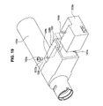
- the lock housing 71 of a lock apparatus 7 integrally with the outer column 4 by die casting.
- an electronic unit 73 which includes an operation mechanism for operating a lock pin 73 A (see FIG. 2 ) using an actuator (not shown).
- the lock pin 73 A is engaged with the key lock groove of the upper steering shaft 102 A to thereby lock the steering shaft 102 against rotation.
- the lock housing 71 is formed to have a hollow box shape which projects from the outer column 4 rightward in the vehicle width direction. When it is viewed in FIG. 5 , the lock housing 71 is symmetric in the vertical direction, while its height H 1 is set substantially equal to the outside diameter dimension of the cylindrical outer periphery 42 of the outer column 4 . Also, the height H 2 of the connecting portion 72 between the outer periphery 42 of the outer column 4 and lock housing 71 is set larger than the outside diameter dimension of the outer periphery 42 of the outer column 4 .
- a connecting surface between the outer periphery 42 of the outer column 4 and connecting portion 72 is formed substantially 3 ⁇ 4 of the periphery of the outer periphery 42 of the outer column 4 , the connecting strength between the lock housing 71 and outer column 4 can be increased. Owing to this, the lock pin elongated hole can be designed small. Also, since the height H 2 of the connecting portion 72 is large, the rigidity of the connecting portion 72 itself is also enhanced.
- Each rib 76 extends from the vehicle body forward side surface 74 toward the vehicle body front side parallel to the axis of the outer column 4 .
- each rib 77 extends from the vehicle body rearward side surface 75 toward the vehicle body rear side parallel to the axis of the outer column 4 .
- the ribs 76 and 77 are respectively formed to have a substantially triangular shape.
- the rigidity of the lock housing 71 is enhanced to thereby increase the strength thereof when the steering shaft is locked. Also, since the lock housing 71 itself may be light in weight, the weight of the whole steering apparatus can be reduced.
- FIG. 6 is a structure view of the main portions of a steering apparatus according to the second embodiment of the invention, corresponding to FIG. 4 .
- description will be given only of the structural portions of the second embodiment different from the above-mentioned first embodiment and thus the duplicate description of the same portions is omitted here. Also, the same parts are given the same reference numerals.
- the second embodiment provides the modified versions of the shape of the connecting portion between the outer periphery 42 of the outer column 4 and lock housing 71 and the shape of the vehicle body front side side surface 74 of the lock housing 71 .
- the lock housing 71 is formed to have a hollow box shape which projects from the outer column 4 to the right in the vehicle width direction. Also, the outer periphery 42 of the outer column 4 and lock housing 71 are connected together by two ribs 78 which respectively project in the radial direction of the outer periphery 42 of the outer column 4 further outwardly than the outside diameter dimension of the outer periphery 42 . This structure can increase the connecting strength between the outer periphery 42 of the outer column 4 and lock housing 71 .
- Each rib 79 extends from the vehicle body forward side surface 74 forwardly of the vehicle body parallel to the axis of the outer column 4 up to the side surface 46 (column fastening surface) of the outer column 4 , thereby enhancing the strength in the twist direction of the outer column 4 .
- Each rib 77 for connecting together the outer periphery 42 of the outer column 4 and the vehicle body backward side surface 75 has the same shape as the rib used in the first embodiment.
- the connecting strength between the outer column 4 and lock housing 71 is greater than that in the first embodiment. This can enhance the rigidity of the lock housing 71 to thereby increase the strength of the lock housing 71 when the steering shaft is locked, and also can reduce the weight of the lock housing 71 itself to thereby reduce the weight of the whole steering apparatus.
- FIG. 7 is a structure view of the main portions of a steering apparatus according to the third embodiment of the invention, corresponding to FIG. 5 .
- description will be given only of such structural portions of the second embodiment as are different from the above-mentioned first embodiment and thus the duplicate description of the same portions is omitted here. Also, the same parts are given the same reference numerals.
- the third embodiment provides the modified version of the shape of the lock housing 71 .
- the lock housing 71 of the lock apparatus 7 integrally with the outer column 4 by die casting.
- the lock housing 71 is formed to have a hollow box shape which projects from the outer column 4 to the right in the vehicle width direction. That is, the housing 71 , when it is viewed in FIG. 7 , is symmetric in shape in the vertical direction and the height H 1 of the right projecting end 711 of the housing 71 is substantially equal to the outside diameter dimension of the cylindrical outer periphery 42 of the outer column 4 . Also, the height H 2 of a connecting portion 72 between the outer periphery 42 of the outer column 4 and lock housing 71 is set larger than the outside diameter dimension of the cylindrical outer periphery 42 of the outer column 4 , while the lock housing 71 is formed tapered from the connecting portion 72 toward the projecting end 711 .
- connecting surface between the outer periphery 42 of the outer column 4 and connecting portion 72 is formed to extend substantially 3 ⁇ 4 of the outer periphery 42 of the outer column 4 , the connecting strength between the lock housing 71 and outer column 4 is increased. Also, since the height H of the connecting portion 72 is large, the rigidity of the connecting portion 72 itself can also be enhanced.
- the third embodiment similarly to the first embodiment, there are provided three thin-plate-shaped ribs (not shown) which are respectively used to connect the outer periphery 42 of the outer column 4 to the vehicle body forward side surface and three thin-plate-shaped ribs 77 which are respectively used to connect the outer periphery 42 of the outer column 4 to the vehicle body rearward side surface.
- the shape of the lock housing 71 since the shape of the lock housing 71 is simplified, the shape of a die for die casting the lock housing 71 can be simplified, thereby being able to enhance the formability of the lock housing 71 .
- FIG. 8 is a perspective view of the main portions of a steering apparatus according to the fourth embodiment of the invention.
- description will be given only of such structural portions of the second embodiment as are different from the above-mentioned first embodiment and thus the duplicate description of the same portions is omitted here. Also, the same parts are given the same reference numerals.
- the fourth embodiment provides an example in which the projecting direction of the lock housing 71 from the outer column 4 is set for a direction going downwardly of the vehicle body.
- the fourth embodiment similarly to the first to third embodiments, on the vehicle body rear side of the outer column 4 , there is formed the lock housing 71 of the lock apparatus 7 integrally with the outer column 4 by die casting.
- an electronic unit 73 having an operation mechanism which operates the lock pin 73 A (see FIG. 2 ) using an actuator (not shown).
- the lock pin 73 A is engaged into the key lock groove of the upper steering shaft 102 A to thereby prevent the steering shaft 102 (see FIG. 1 ) against rotation.
- the lock housing 71 is formed as a hollow box which projects from the outer column 4 downwardly of the vehicle body and the vehicle body downward side of which is opened.
- the lock housing 71 is symmetric in shape in the vehicle body right and left direction, and the width of the lock housing 71 in the vehicle body right and left direction is set substantially equal to the outside diameter dimension of the cylindrical outer periphery 42 of the outer column 4 . Also, the width of a connecting portion between the outer periphery 42 of the outer column 4 and lock housing 71 in the vehicle body right and left direction is set larger than the outside diameter dimension of the outer periphery 42 of the outer column 4 .
- the connecting surface between the outer periphery 42 of the outer column 4 and connecting portion 72 is formed to extend substantially 3 ⁇ 4 of the outer periphery 42 of the outer column 4 , the connecting strength between the lock housing 71 and outer column 4 is increased, thereby being able to reduce the size of the lock pin elongated hole. Also, since the width of the connecting portion 72 in the vehicle body right and left direction is large, the rigidity of the connecting portion 72 itself is enhanced.
- the extension range of the connecting surface between the outer periphery 42 of the outer column 4 and connecting portion 72 is not limited to 3 ⁇ 4 of the outer periphery 42 of the outer column 4 , but it may also be selected differently depending on cases; for example, 1 ⁇ 2 to 4 ⁇ 5 of the outer periphery 42 of the outer column 4 can also be selected.
- the lock housing 71 on the vehicle body forward side (in FIG. 8 , the left) surface and backward side (in FIG. 8 , the right) surface of the lock housing 71 , there may be provided multiple thin-plate-shaped ribs which are respectively used to connect the outer periphery 42 of the outer column 4 to the vehicle body forward side surface and to connect the outer periphery 42 of the outer column 4 to the vehicle body rearward side surface.
- the lock housing 71 is formed to project from the outer column 4 in the vehicle width direction.
- the lock housing 71 is formed to project from the outer column 4 in the vehicle width direction, preferably, there can be avoided a possibility that the knees of a driver can hit against the lock housing 71 , and also the visibility of a meter panel can be enhanced.
- the lock housing 71 is formed to project from the outer column 4 in the vehicle downward direction, the visibility of a meter panel can be enhanced. Also, before the steering apparatus is mounted onto the vehicle body, when assembling peripheral parts to the steering apparatus, the steering apparatus may be turned upside down. In this case, when the lock housing 71 projects from the outer column 4 in the vehicle downward direction, it is easy to incorporate the electronic unit 73 of the lock apparatus 7 and arrange wiring.
- the mold removing direction provides the vehicle width direction (a direction perpendicular to the right and left side surfaces 46 of the outer column 4 ). Therefore, when the lock housing 71 is formed to project from the outer column 4 in the vehicle width direction, preferably, it is easy to form the lock housing 71 . Also, as in the fourth embodiment, when the lock housing 71 is formed to project from the outer column 4 in the vehicle downward direction, the mold removability is good when the mold removing direction provides the vehicle body vertical direction.
- the inner column 3 is constituted of a lower column and the outer column 4 is constituted of an upper column
- the inner column 3 may also be constituted of an upper column and the outer column 4 may also be constituted of a lower column.
- the slit structure may also be applied to a column structured such that only the lower portions of the column fastening surfaces 46 are connected together to connect together the column fastening surfaces 46 .
- the invention in the first to fourth embodiments, description has been given of an example in which the invention is applied to a tilt/telescopic type of steering apparatus capable of adjusting both its tilt position and telescopic position.
- the invention may also be applied to a steering apparatus capable of adjusting one of its tilt position and telescopic position; or, to a steering apparatus structured such that it adjusts neither its tilt position nor its telescopic position.
- the reduction mechanism of an electric power steering apparatus there may be mounted on the portion near to the mounting position of the vehicle body mounting lower bracket 12 .
- the fifth to tenth embodiments respectively relate to a steering apparatus which can enhance the rigidity of a housing and also, while securing the freedom of the design of the steering apparatus, can enhance its antitheft function.
- FIGS. 22 and 23 respectively show a conventional steering apparatus disclosed in the patent reference 1.
- this steering apparatus on the inside diameter side of a cylindrical steering column 1002 supported on a vehicle body 1001 , there is rotatably supported a steering shaft 1003 .
- a steering wheel 1004 To the rear end portion of the steering shaft 1003 that projects backwardly beyond the rear end opening of the steering column 2 , there is fixed a steering wheel 1004 .
- a steering column and a steering shaft which are respectively of a telescopic type.
- the back and forth positions of an outer column and an inner column constituting such telescopic type of steering column, and the back and forth positions of an outer tube and an inner shaft constituting such telescopic type of steering shaft may also be reversed to those of the structure shown in FIG. 21 .
- a lock housing 1009 is fixed to a portion of a steering column 1002 a using a clamp metal member 1010 and a pair of bolts 1011 and 1011 .
- the lock housing 1009 includes a tubular-shaped storage portion 1012 , a bottom plate portion 1013 provided in a state where it closes the base end opening of the storage portion 1012 , and a pair of mounting flange portions 1014 and 1014 disposed in such a manner that they project from the base end portion outer peripheral surface of the storage portion 1012 .
- a through hole (not shown)
- a portion of the steering column 1002 a that is matched to the through hole of the bottom plate portion 1013
- another through hole not shown
- such portion of a steering shaft 1003 a the axial position of as coincides with the above two through holes is formed as a male spline shape having a rough pitch, whereby there are formed multiple key lock grooves 1015 , 1015 in the multiple portions of the steering shaft 1003 a in the circumferential direction thereof.
- a lock unit 1016 is stored into the lock housing 1009 and further the lock unit 1016 is fixed to the interior of the lock housing 1009 using a fixing screw 1017 .
- the fixing screw 1017 in a state where it is inserted into a recessed hole 1018 formed in the lock housing 1009 , is threadedly engaged into a screw hole 1019 formed in the lock unit 1016 and is then fastened further.
- the lock unit 1016 includes a lock pin 1021 which can be advanced and retreated by an electric actuator 1020 .
- the above-structured lock apparatus operates in the following manner. That is, when an ignition key is rotated up to a lock position, the actuator 1020 advances the lock pin 1021 toward the inside diameter portion of the steering column 1002 a . To the lock pin 1021 , there is applied by an elastic portion (not shown) an energizing force in a direction where the lock pin 1021 is made to advance. Owing to this, the lock pin 1021 penetrates through the two through holes and the leading end of the lock pin 1021 moves into the grooves of the key lock grooves 1015 , whereby the lock pin 1021 prevents the steering shaft against rotation.
- the opening of the recessed hole 1018 in which the head portion 1022 of the fixing screw 1017 for fixing the lock unit 1016 is stored, is covered with the steering column 1002 a .
- the fixing screw 1017 cannot be operated. Therefore, it is possible to prevent the fixing screw 1017 from being loosened and thus to prevent the lock unit 1016 from being removed from the lock housing 1009 .
- the pair of bolts 1011 and 1011 which connect and fix the lock housing 1009 and clamp metal member 1010 to each other, are exposed, there is a possibility that a sufficient antitheft effect cannot be always obtained.
- one of the two bolts 1011 and 1011 can be made inoperable, for example, by disposing it such that it adjoins and opposes a portion fixed to the vehicle body, it is difficult to design such that neither of the two bolts 1011 and 1011 can be operated. In other words, undesirably, the freedom of the design of the steering apparatus is impaired.
- FIGS. 9 to 14 respectively show the fifth embodiment according to the invention.
- the description of such structures and operations of the fifth embodiment as are similar to the above conventional steering apparatus is omitted or simplified, and thus description will be given below mainly of the characteristic portions of the present embodiment.
- the lock housing 1009 a is formed integrally with the steering column (for example, outer column) 1002 b . That is, by die casting a light alloy such as an aluminum alloy and a magnesium alloy, the lock housing 1009 a and steering column 1002 b are formed as an integral body. Therefore, the lock housing 1009 a and steering column 1002 b are connected to each other in such a manner that they cannot be separated from each other.
- the steering column 1002 b is formed as an outer column for constituting a telescopic type of steering apparatus which is used to adjust the back and forth positions of a steering wheel.
- a slit 1023 for elastically increasing or decreasing the diameter of the steering column 1002 b
- two bracket portions 25 which are disposed such that they sandwich the slit 1023 from both sides and also which respectively include an elongated hole 1024 formed long in the axial direction thereof.
- the structure and operation of a telescopic type of steering apparatus including such elongated hole 1024 and bracket portion 25 are conventionally widely known and are not associated with the subject matter of the present invention. Thus, the illustration and description thereof are omitted here.
- the lock housing 1009 a is disposed on the outer peripheral surface of the steering column 1002 b in such a manner that it is opened outwardly in the diameter direction of the steering column 1002 b . Also, in such portion of the steering column 1002 b as is matched to the lock housing 1009 a (the portion that is surrounded by the lock housing 1009 a ), there is formed a through hole 1026 (see FIG. 12 ). The through hole 1026 penetrates through the steering column 1002 b in the diameter direction thereof.
- a lock collar 1027 is fitted with and fixed to the outer surface of such portion of the steering shaft 1003 b rotatably supported on the inside diameter side of the steering column 1002 b as faces the through hole 1026 .
- the lock collar 1027 is fixed to the steering shaft 1003 b by welding or the like in such a manner that it can be prevented against rotation even when a large rotational force is applied to the lock collar 1027 .
- elongated holes (not shown) respectively long in the axial direction of the lock collar 1027 , while they are used as key lock grooves into which the leading end portion of the lock pin 1021 a can be engaged.
- the shape and the like of such lock collar 1027 are also conventionally widely known and thus the detailed description thereof is omitted here.
- the fixed state of the lock collar 1027 to the steering shaft 1003 b may not be such that it is completely prevented against rotation with respect to the steering shaft 1003 b . That is, the lock collar 1027 may only be fitted with the outer surface of the steering shaft 1003 b in such a manner that it can generate resistance of such degree as can substantially prevent execution of a steering operation by the steering wheel. Therefore, the lock collar 1027 may also be fitted with the outer surface of the steering shaft 1003 b by close fit, or may be fitted with such outer surface through a sleeve-like member which is made of a plate spring or the like and also which can generate large frictional resistance.
- a screw hole 1019 a In the deep end face of the lock unit 1016 a , that is, in the surface of the lock unit 1016 a facing such portion of the outer peripheral surface of the steering column 1002 b as is surrounded by the lock housing 1009 a , there is formed a screw hole 1019 a . With the screw hole 1019 a , there can be threadedly engaged a fixing screw 1017 a which is used to fix the lock unit 1016 a to the inside of the lock housing 1009 a.
- a second through hole 1028 is formed in such portion of the portion of the steering column 1002 b surrounded by the lock housing 1009 a as is shifted from the through hole 1026 and is matched to the screw portion 1019 a .
- the second through hole 1028 is formed to have a size which allows the shaft portion 1029 of the fixing screw 1017 a to pass therethrough but prevents the head portion 1022 a of the fixing screw 1017 a against passage.
- a recessed portion 1030 which is capable of storing the head portion 1022 a therein.
- a third through hole 1031 having a size which allows the head portion 1022 a of the fixing screw 1017 a to pass therethrough.
- the lock unit 1016 a may be inserted into the lock housing 1009 a from the lock pin 1021 a and screw hole 1019 a.
- the shaft portion 1029 of the fixing screw 1017 a having passed through the third through hole 1031 is inserted into the second through hole 1028 and a male screw formed in the outer peripheral surface of the shaft portion 1029 is threadedly engaged with the screw hole 1019 a .
- a tool such as a driver is inserted from the third through hole 1031 to fasten the fixing screw 1017 a , whereby the lock unit 1016 a is fixed to the inside of the lock housing 1009 a.
- the steering shaft 1003 b is assembled to the inside diameter side of the steering column 1002 b.
- the steering shaft 1003 b is situated between the second and third through holes 1028 and 1031 . Therefore, even when a tool is inserted from the third through hole 1031 , the tool is prevented from being engaged with the head portion 1022 a of the fixing screw 1017 a . That is, according to the present embodiment, while the steering shaft 1003 b is left situated within the steering column 1002 , the fixing screw 1017 a cannot be loosened. In other words, while the function of the steering apparatus remains secured, the lock unit 1016 a is prevented from being removed from the lock housing 1009 a.
- the lock housing 1009 a is formed integrally with the steering column 1002 b , even a tool such as a file or a hack-saw is used, it takes a long time to separate the lock housing 1009 a together with the lock unit 1016 a from the steering column 1002 b . This can enhance the antitheft function.
- the steering column 1002 b and lock housing 1009 a are formed an integral body, it is possible to facilitate the assembling operation and thus to reduce the manufacturing cost of the steering apparatus.
- steering column 1002 b and lock housing 1009 a are formed an integral body, the size and weight of the whole steering apparatus with a lock apparatus incorporated therein can be reduced.
- FIG. 15 shows a sixth embodiment according to the invention.
- the present embodiment on such portion of the outer peripheral surface of the steering shaft 1003 b as faces the through hole 1026 (see FIG. 12 ), there are formed rough male-spline-groove-shaped uneven portions respectively serving as lock collars 1027 a which can be fitted with and fixed to the outer surface of such portion.
- the structures and operations of the other remaining portions of the present embodiment are similar to those of the above-mentioned fifth embodiment, and thus the illustration and description of the equivalent portions thereof are omitted here.
- FIG. 16 shows a seventh embodiment according to the invention.
- a backup piece 1032 which is formed to have a partial arc shape to match the shape of, for example, the inner peripheral surface of the steering column 1002 b.
- the backup piece 1032 prevents the steering shaft 1003 b from shifting in a direction where it parts away from the lock housing 1009 a . That is, in a state where the lock pin 1021 a (see FIGS. 9 and 12 ) and key lock groove are engaged with each other, when trying to rotate the steering shaft 1003 b through the steering wheel with a large force, there is a possibility that the steering shaft 1003 b can shift in a direction to part away from the lock housing 1009 a to thereby remove the engagement between the lock pin 1021 a (see FIGS. 9 and 12 ) and key lock groove.
- the backup piece 1032 can prevent the steering shaft 1003 b from shifting in a direction to part away from the lock housing 1009 a and thus can prevent the removal of the engagement between the lock pin 1021 a and key lock groove, thereby being able to secure the antitheft function of the lock apparatus.
- the backup piece 32 in a vehicle crash, is slipped down from the inner peripheral surface of the steering column 1002 to thereby prevent the steering shaft 1003 b from shifting forwardly.
- the structures and operations of the other remaining portions of the present embodiment are similar to those of the above-mentioned fifth and sixth embodiments, and thus the illustration and description of the equivalent portions thereof are omitted here.
- FIGS. 17 and 18 respectively show an eighth embodiment according to the invention.
- a steering column (outer column) 1002 c is made of steel and a lock housing 1009 b is made of a light alloy. They are both formed by die casting into an integral body. Specifically, a portion of the outer column 1002 c is embedded into a portion of the lock housing 1009 b to thereby form them as an integral body. In this manner, the outer column 1002 c and lock housing 1009 b are connected together in such a manner that they cannot be separated from each other.
- the structures and operations of the other remaining portions of the present embodiment are similar to the above-mentioned fifth embodiment. Thus, the illustration and description of the equivalent portions are omitted here.
- FIG. 19 shows a ninth embodiment according to the invention.
- a steering column 1002 c made of steel and a lock housing 1009 b made of a light alloy are formed into an integral body.
- a recessed portion 1033 which is recessed downwardly of the longitudinal direction central and rear end portions of the above upper surface.
- a second through hole 1028 a having a size which allows the shaft portion 1029 of the fixing screw 1017 a to pass therethrough but prevents the head portion 1022 a of the fixing screw 1017 a from passing therethrough.
- the outer peripheral surface of the lock unit 1016 a is formed to have a shape substantially equal to or slightly smaller than the shape of the inner peripheral surface of the lock housing 1009 b .
- a screw hole 1019 b In such portion of the upper surface of the lock unit 1016 a as is matched to the second through hole 1028 a , there is formed a screw hole 1019 b .
- a male screw formed in the shaft portion 1029 of the fixing screw 1017 a can be threadedly engaged with the screw hole 1019 b .
- the lock unit 1016 a can be supported by and fixed to the inside of the lock housing 1009 b.
- the clearance between the upper surface of the lock housing 1009 b and the portion to be fixed to the vehicle body should be set substantially equal to the axial dimension of the head portion 1022 a of the fixing screw 1017 a , or a level difference the recessed portion 1033 and lock housing 1009 b should be set substantially equal to the axial dimension of the head portion 1022 a of the fixing screw 1017 a .
- the structures of the other remaining portions of the present embodiment are similar to the above-mentioned fifth embodiment. Thus, the duplicate illustration and description of the equivalent portions are omitted here.
- the lock unit 1016 a since, while securing the function of the steering apparatus, the lock unit 1016 a is prevented from being removed from the lock housing 1009 a , the antitheft function of the lock apparatus can be enhanced.
- FIG. 20 shows a tenth embodiment according to the invention.
- a second through hole 1028 a having a size which allows the shaft portion 1029 of the fixing screw 1017 a to pass therethrough but prevents the head portion 1022 a of the fixing screw 1017 a from passing therethrough.
- a screw hole 1019 c with which there can be threadedly engaged a male screw formed in the shaft portion 1029 of the fixing screw 1017 a .
- the lock unit 1016 a can be supported by and fixed to the inside of the lock housing 1009 b.
- the structure of the lock unit is not limited to any specific one. That is, besides the above-mentioned structure in which, by rotating an ignition key up to the lock position, the lock pin is projected from the inner peripheral surface of the steering column, there may also be employed a structure in which the lock pin is left projected from the inner peripheral surface of the steering column unless a regular key is used.
- the eleventh to twenty-second embodiments respectively relate to a steering apparatus which is enhanced in the rigidity of a housing, includes a housing structured such that, whether the steering apparatus is mounted on a right-hand drive vehicle or a left-hand drive vehicle, a portion not in use is left therein, and, even when the slit of a clamp device and the through hole of a lock apparatus are disposed adjacent to each other, a crack is hard to occur between the slit and through hole.
- a steering shaft 2002 with a steering wheel 2001 fixed to the rear end portion thereof is rotatably supported on the inside diameter side of a steering column 2003 which is supported on the vehicle body.
- a steering shaft 2002 With a steering wheel 2001 fixed to the rear end portion thereof is rotatably supported on the inside diameter side of a steering column 2003 which is supported on the vehicle body.
- an intermediate shaft 2005 To the front end portion of the steering shaft 2002 , there is connected the rear end portion of an intermediate shaft 2005 through a universal joint 2004 .
- a steering gear unit 2007 which is constituted of a rack and pinion and the like.
- FIGS. 44 and 45 respectively show an example of a conventional structure of a steering apparatus having such steering wheel position adjusting function.
- FIG. 44 is a side view of the rear end side portion of the conventional structure
- FIG. 45 is a partially omitted view of the conventional structure when it is viewed from below FIG. 44 .
- a steering column 2003 a constituting the conventional structure is produced in the following manner. That is, a cylindrical outer column 2010 situated on the rear side of the vehicle body (on the right side in FIGS. 44 and 45 , and in FIGS. 24, 25, 35, 36, 38, 40, 42, 46, 48 and 49 which will be respectively discussed later) and a cylindrical inner column 2011 situated on the front side of the vehicle body (on the right side in FIGS. 44 and 45 , and in FIGS. 24, 25, 35, 36, 38, 40, 42, 46, 48 and 49 which will be respectively discussed later) are combined together in such a manner that the whole length thereof can be increased or decreased, that is, a telescopic manner.
- These outer column 2010 and inner column 2011 are respectively formed of a light alloy such as an aluminum alloy and a magnesium alloy by die casting.
- the front end portion is supported in such a manner that it can be only oscillated about a transverse shaft 2012 with respect to the vehicle body.
- its front end portion to its front half section is fitted with the outer surface of the rear end portion to its rear half section in such a manner that it can be shifted only in the axial direction.
- a slit 2013 which is opened on the front end edge of the outer column 2010 and extends in the axial direction of the outer column 2010 . And, owing to formation of such slit 2013 , the diameter dimension of the front half section of the outer column 2010 can be elastically changed easily.
- Such portion of the intermediate portion of the steering column 2003 a as corresponds to the engagement portion between the outer column 2010 and inner column 2011 is supported by a clamp device 2014 which is fixed to the vehicle body.
- the clamp device 2014 can be switched by the rotational operation of a lever 2015 between a state where it applies fastening forces to such portion of the outer column 2010 as ranges from the front end portion thereof to the outer peripheral surface of the front end side thereof from both sides in the right and left direction (in the front and back direction in FIG. 44 , and FIGS. 24, 33, 35, 38, 40, 42 and 46 to be discussed later; in the vertical direction in FIG. 45 , and FIGS. 25, 36, 48 and 49 to be discussed later; in the right and left direction in FIGS. 26, 27, 29 to 32, 34, 37, 39, 41, 47A and 47B to be discussed later) which is the width direction of the vehicle body, and a state where it does not apply such fastening forces.
- a steering shaft 2002 a is structured such that it can bring the front end portion of a circular-pipe-shaped outer shaft 2016 disposed on the rear side of the vehicle body and the rear end portion of a rod-shaped inner shaft 2017 disposed on the front side of the vehicle body into engagement with each other to thereby be able to transmit its rotation force and also to increase or decrease the whole length thereof.
- the rear end side of the outer shaft 2016 is supported on the rear end portion of the outer column 2010 and the front end side of the inner shaft 2017 is supported on the front end portion of the inner column 2011 respectively by their respective antifriction bearings (not shown) such as radial ball bearings in such a manner that only the rotational movements thereof are allowed.
- antifriction bearings such as radial ball bearings
- the steering wheel 2001 (not shown in FIG. 44 or 45 ; see FIG. 43 ).
- the rear end portion of the intermediate shaft 2005 is connected to such portion of the front end portion of the inner shaft 2017 as projects forwardly from the front end of the inner column 2011 .
- the state where the fastening force given by the clamp device 2014 is applied and the state where such fastening force is not applied are switched over to each other to thereby adjust the position of the steering wheel 2001 in the following manner.
- FIGS. 46, 47A and 47B respectively show, as an example of a conventionally used lock apparatus for preventing the theft of a vehicle, a lock apparatus disclosed in the patent reference 5.
- this lock device when an ignition switch is turned off and also, in order to remove an ignition key from a key hole (not shown), the ignition key is turned up to its lock position, as shown in FIG. 47A , a lock pin 2018 is elastically projected from a key cylinder (not shown) fixed to the steering column 2003 b inwardly in the diameter direction of the steering column 2003 b through a through hole 2020 formed in the steering column 2003 b.
- the leading end portion of the lock pin 2018 is inserted into and engaged with the key lock hole 2021 of a key lock collar 2019 fixed to the steering shaft 2002 b . And, such engagement prevents the rotation of the steering shaft 2002 b .
- the lock pin 2018 does not project inwardly of the steering column 2003 b but the steering shaft 2002 b with the key lock collar 2019 fixed thereto is allowed to rotate.
- the lock housing of a lock unit including a key cylinder must be provided on the outer peripheral surface of the rear end side of the outer column 2010 .
- FIG. 48 shows an example in which the structure of the lock housing disclosed in the patent reference 2 is applied to the rear end side of the outer column 2010 .
- a pair of plate-shaped lock housings 2022 a and 2022 b which respectively project on both sides in the width direction of a vehicle, are formed by die casting integrally with the outer column 2010 .
- one of the paired lock housings 2022 a and 2022 b can be chosen as a lock housing on which the lock unit is to be mounted.
- the through hole 2020 (see FIGS. 46, 47A and 47B ), into which the lock pin 2018 can be inserted, must be formed in the rear end portion of the outer column 2010 .
- FIG. 49 shows an example in which the through hole 2020 is formed in the rear end portion of the outer column 2010 .
- the periphery of the through hole 2020 of the outer column 2010 provides a portion which is reduced in strength when compared with the other remaining portion.
- FIG. 49 in the structure where the through hole 2020 is formed in a portion near to the rear end edge of the slit 2013 , due to the stress that is generated when the fastening force by the clamp device (see FIG. 44 ) is applied, there is raised a possibility that there can be caused a crack K between the slit 2013 and through hole 2020 .
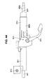
- FIGS. 24 to 26 respectively show the eleventh embodiment according to the invention.
- the present embodiment is characterized by the structure of a lock apparatus which is provided on the rear end side of an outer column 2010 a constituting a steering column 2003 c .
- the structures and operations of the present embodiment similar to those of the above-mentioned conventional steering apparatus are omitted or simplified here. That is, description will be given below mainly of the characteristic portions of the present embodiment.
- a through hole 2020 a which allows the inside and outside of the outer column 2010 a to communicate with each other. Also, in such portion of the lower half section of the rear end side of the outer column 2010 a as surrounds the periphery of the through hole 2020 a , there is formed by die casting a box-like lock housing 2023 with its lower surface opened in such a manner that it projects downwardly from the above portion and is formed integrally with the outer column 2010 a.
- the lock housing 2023 includes: a front plate portion 2024 and a rear plate portion 2025 respectively formed in such a manner that they extend parallel to each other downwardly from the two front and rear end edge portions of the through hole 2020 a ; and, a pair of parallel side plate portions 2027 a and 2027 b respectively formed in such a manner that they extend downwardly from the two right and left end edge portions of the through hole 2020 a through a pair of connecting plate portions 2026 a and 2026 b extending right and left.
- the two right and left end portions of the front plate portion 2024 and rear plate portion 2025 and the two front and rear end portions of the connecting plate portions 2026 a , 2026 b and side plate portions 2027 a and 2027 b are respectively formed to continue with each other. Also, in the two mutually matched front and rear end portions of the lower sides of the side plate portions 2027 a and 2027 b , there are formed insertion holes 2028 and 2028 respectively.
- a cylindrical key lock collar 2019 a is fitted with and fixed to the outer surface of such portion of the rear end side of the outer shaft 2016 rotatably supported on the inside diameter side of the outer column 2010 a as is matched to the through hole 2020 a in the axial direction.
- the key lock collar 2019 a there are formed multiple key lock grooves 2047 , 2047 , which are respectively key lock recessed portions, at regular intervals in the circumferential direction thereof.
- the lock unit 2029 includes a columnar portion 2030 and the above-mentioned held portion 2031 which is fixed to the upper portion of the columnar portion 2030 and has a substantially rectangular block (cuboid) shape.
- the columnar portion 2030 includes a key hole (not shown) which formed in one (in FIG. 24 , the deep side) axial-direction end face thereof and into which an ignition key can be inserted.
- the held portion 2031 as shown in FIG. 25 , can be inserted through the lower surface opening of the lock housing 2023 into the lock housing 2023 without shaking greatly.
- the held portion 2031 includes a recessed surface portion 2032 which is formed in the right-and-left direction intermediate portion of the upper surface of the held portion 2031 and also which has a radius of curvature slightly larger than the radius of curvature of the inner peripheral surface of the outer column 2010 a.
- a cylinder hole 2033 the upper end portion of which is opened in the central portion of the recessed surface portion 2032 ; and, into the inside of the cylinder hole 2033 , there is inserted a lock pin (not shown).
- a pair of insertion holes 2034 and 2034 which are arranged concentric with the insertion holes 2028 and 2028 respectively.
- the dimensions of the respective members are regulated in such a manner that the dimensions a 1 , a 2 , b 1 , b 2 , c 1 , c 2 , d 1 , d 2 , e 1 , e 2 of clearances respectively existing between the lock housing 2023 , held portion 2031 and the respective bolts 2035 , 2035 can be reduced sufficiently, or can be set for 0 or negative values (a state of light pressure insertion).
- the above is the structure of the lock apparatus according to the present embodiment.
- the above lock apparatus operates in the following manner. That is, when the ignition switch is turned off and, in order to pull out the ignition key from the above key hole, the ignition key is turned up to the lock position, a lock pin (not shown) is elastically projected inwardly in the diameter direction of the outer column 2010 a from the cylinder hole 2033 formed in the held portion 2031 through the through hole 2020 a formed in the lower surface of the outer column 2010 a . And, the leading end portion of the lock pin is inserted into and engaged with the key lock groove 2047 of the key lock collar 2019 a fixed to the steering shaft 2002 a . This engagement prevents the rotation of the steering shaft 2002 a.
- the lock housing 2023 which is used to mount the lock unit 2029 onto the outer column 2010 a , is formed such that it does not project rightward or leftward of the outer column 2010 a greatly but projects mainly downwardly.
- the lock housing 2023 can be used in common. Also, since only one lock housing 2023 may be provided, in a state where the lock apparatus is assembled to the vehicle, there is no possibility that a lock housing not in use can occur.
- the lock housing 2023 is formed in such a manner that it is connected to such portion of the outer column 2010 a as exists around the through hole 2020 a . Owing to this, the peripheral portion of the through hole 2020 a can have sufficient strength.
- the front plate portion 2024 constituting the lock housing 2023 is formed in such a manner that it partitions a portion, which exists between the slit 2013 formed in the front half section of the lower surface of the outer column 2010 a and the through hole 2020 a formed in the rear end portion of the lower surface of the outer column 2010 a , in the back and forth direction of the outer column 2010 a . Therefore, even when the fastening force is applied by the clamp device 2014 to generate internal stress in the outer column 2010 a , the front plate portion 2024 can prevent a crack from occurring between the rear end edge of the slit 2013 and the above through hole 2020 a.
- FIGS. 27 and 28 respectively show a twelfth embodiment according to the invention.
- the head portion 2037 a of a bolt 2035 a has a cylindrical outer peripheral surface and a hexagonal hole 2039 formed in the base end face thereof. Also, between the head portion 2037 a and one (in FIG. 27 , the left) side plate portion 2027 a constituting a lock housing 2023 , there is interposed a washer 2040 .
- a nut 2038 is fitted with the inner surface of a tubular portion 2041 which is provided on and projected from the outer surface of the other side plate portion 2027 b constituting the lock housing 2023 . And, the outer peripheral surface of the hexagonal-shaped nut 2038 is engaged with the inner peripheral surface of the hexagonal-shaped tubular portion 2041 to thereby prevent the nut 2038 from being rotated from outside.
- the leading end portion of the shaft portion 2036 of the bolts 2035 a is threadedly engaged with the nut 2038 and is fastened further by a hexagonal wrench (not shown) engaged with the hexagonal hole 2039 of the head portion 2037 a of the bolt 2035 a , the nut 2038 can be prevented from rotating together with the bolt 2035 a.
- a friction sleeve 2042 between the outer peripheral surface of the outer shaft 2016 and the inner peripheral surface of a key lock collar 2019 a , there is interposed a friction sleeve 2042 .
- the friction sleeve 2042 allows the key lock collar 2019 a to rotate relative to the outer shaft 2016 with a large torque. Therefore, according to the present embodiment, in a state where a lock pin and a key lock groove 2047 are engaged with each other, unless there is applied such a large torque to a steering wheel as the steering wheel cannot be operated, it is impossible to operate the steering wheel. Therefore, the present embodiment can secure its antitheft function and also can prevent the damage of the lock pin and the like.
- the remaining structures and operations of the present embodiment are similar to those of the previously described eleventh embodiment.
- FIG. 29 shows a thirteenth embodiment according to the invention.
- the head portion 2037 a of a bolt 2035 a into the inside of an insertion hole 2028 a formed in one (in FIG. 29 , left) side plate portion 2027 a constituting a lock housing 2023 , there is inserted the head portion 2037 a of a bolt 2035 a .
- the head portion 2037 a of the bolt 2035 a and a nut 2038 threadedly engaged with the leading end portion of the shaft portion 2036 of the bolt 2035 a cooperate together in sandwiching a held portion 2031 and the other (in FIG. 29 , right) side plate portion 2027 b constituting the lock housing 2023 between them.
- the mutually opposed side surfaces of the held portion 2031 and the other side plate portion 2027 b are contacted with each other.
- the held portion 2031 can be prevented from shaking in the right and left direction with respect to the lock housing 2023 . Also, since a clearance between the outer peripheral surface of the head portion 2037 a of the bolt 2035 a and the inner peripheral surface of the insertion hole 2028 a is set for a value in the range of approximately 0.1 mm to the light pressure insertion level, these two peripheral surfaces can be prevented from shaking in the diameter direction relative to each other.
- the remaining structures and operations of the present embodiment are similar to those of the previously described eleventh and twelfth embodiments.
- FIGS. 30 to 32 respectively show fourteenth to sixteenth embodiments according to the invention.
- the structures of the shaft portions 2036 b , 2036 c and 2036 d of bolts 2035 b , 2035 c and 2035 d are different from the above-mentioned thirteenth embodiment.
- an engaging portion 2042 b which expands outwardly in the diameter direction from the outer peripheral surface and also which has an outer peripheral surface having a semicircular arc shaped section.
- an engaging portion 2042 c which expands in the diameter direction from the outer peripheral surface and also which has a cylindrical outer peripheral surface.
- an engaging portion 2042 d which expands in the diameter direction from the outer peripheral surface and also which has a tapered outer peripheral surface, while the tapered outer peripheral surface is inclined in a direction where the outside diameter thereof increases as it goes toward the base end side of the shaft portion 2036 d.
- the engaging portions 2042 b , 2042 c and 2042 d are respectively inserted, or light pressure inserted or pressure inserted into the inside of an insertion hole 2034 formed in a held portion 2031 with a fit clearance of approximately 0.1 mm. Owing to such structure, it is possible to effectively prevent the shaft portions 2036 b , 2036 c and 2036 d and insertion hole 2034 from shaking relative to each other.
- the remaining structures and operations of these embodiments are similar to those of the previously described thirteenth embodiment.
- the engaging portion to be formed in the shaft portion of the bolt is formed integrally with the shaft portion.
- the engaging portion may also be formed of resin, rubber, soft metal or the like as a separate member.
- the separate member may have a ring shape the whole periphery of which is continuously connected, or may have a partially chipped ring shape a portion of which, in the circumferential direction thereof, has a discontinuous portion.
- FIG. 33 shows a seventeenth embodiment according to the invention.
- the present embodiment is different from the eleventh embodiment shown in FIGS. 24 to 26 in that, in the longitudinal direction two end edges of one side plate portion 2027 a constituting the lock housing 2023 , there are formed a pair of second slits which are opened in the lower end edge of the side plate portion 2027 a.
- one side plate portion 2027 a can be easily deformed elastically in a direction where it moves toward and away from the other side plate portion 2027 b (see FIG. 26 ).
- fastening the respective nuts 2038 and 2038 (not shown in FIG. 33 ; see FIGS.
- one side plate portion 2027 a is elastically deformed toward the other side plate portion 2027 b , whereby the inner surfaces of the two side plate portions 2027 a and 2027 b are respectively contacted with the two side surfaces of the held portion 2031 (with no clearance between them).
- This structure can prevent the held portion 2031 from shaking in the right and left direction with respect to the lock housing 2023 .
- the remaining structures and operations of the present embodiment are similar to those of the previously described eleventh embodiment shown in FIGS. 24 to 26 .
- the other side plate portion 2027 b when enforcing the present invention, in order that, using the above-mentioned structure of the seventeenth embodiment, the other side plate portion 2027 b can be easily deformed elastically, in the longitudinal direction two end portions of the other side plate portion 2027 b as well, there may also be formed second slits which are respectively opened in the lower end edge of the side plate portion 2027 b.
- FIG. 34 shows an eighteenth embodiment according to the invention.
- a structure which can easily deform elastically a pair of side plate portions 2027 a and 2027 b constituting a lock housing 2023 in a direction where they move toward and away from each other.
- the number and positions of the second slits to be formed in the side plate portions constituting the lock housing can be changed according to cases.
- FIGS. 35 to 37 respectively show a nineteenth embodiment according to the invention.
- the present embodiment is different from the eleventh embodiment shown in FIGS. 24 to 26 in that a lock housing 2023 a excludes one side plate portion 2027 a and a pair of connecting plate portions 2026 a and 2026 b (see FIGS. 24 to 26 ). Also, due to such exclusion, in the present embodiment, the dimension of a held portion 2031 a in the right and left direction is reduced accordingly. And, the head portions 2037 , 2037 of the bolts 2035 , 2035 (not shown in FIG.
- FIGS. 38 and 39 respectively show a twentieth embodiment according to the invention.
- the present embodiment is different from the above-mentioned nineteenth embodiment in that a connecting band 2044 made of metal is used as a connecting member for connecting the held portion 2031 a to a lock housing 2023 a.
- the intermediate portion of the connecting band 2044 is provided over the upper half section of the outer column 2010 a in such a manner that their peripheral surfaces are contacted with each other with no clearance between them, while the side plate portion 2027 b constituting the lock housing 2023 a and the held portion 2031 a are sandwiched by and between the two end portions of the connecting band 2044 from both right and left sides. Also, in a state where the shaft portions 2036 , 2036 of the bolts 2035 , 2035 (which are not shown in FIG.
- the inner surface of one end portion (in FIG. 41 , left end portion) of the connecting band 2044 and the inner surface of the side plate portion 2027 b constituting the lock housing 2023 a are respectively contacted with the two side surfaces of the held portion 2031 a (with no clearance between them).
- the connecting strength of the held portion 2031 a in the vertical direction with respect to the lock housing 2023 a can be enhanced.
- the structures and operations of the remaining portions of the present embodiment are similar to the above-mentioned nineteenth embodiment.
- FIGS. 40 and 41 respectively show a twenty-first embodiment according to the invention.
- the present embodiment is different from the twentieth embodiment shown in FIGS. 38 and 39 in that a lock housing 2023 b excludes the side plate portion 2027 b (see FIG. 39 ).
- the two end portions of a connecting band 2044 a are contacted with the two side surfaces of a held portion 2031 a respectively.
- a rectangular-shaped thickness reduced portion 2046 in the intermediate portion of the connecting band 2044 a , there is formed a rectangular-shaped thickness reduced portion 2046 . This can reduce the weight of the connecting band 2044 a and also can enhance the bending property of the intermediate portion of the connecting band 2044 a , whereby the intermediate portion of the connecting band 2044 a can be easily contacted closely with the outer peripheral surface of the upper half section of the outer column 2010 a .
- the structures and operations of the remaining portions of the present embodiment are similar to the above-mentioned twentieth embodiment.
- FIG. 42 shows a twenty-second embodiment according to the invention.
- a front plate portion 2024 a and a rear plate portion 2025 a respectively constituting a lock housing 2023 c are formed to extend over the whole area of the outer peripheral surface of the outer column 2010 a . This enhances the strength of the outer column 2010 a , front plate portion 2024 a and rear plate portion 2025 a.
- the size (the dimension in the axial direction of the outer column 2010 a and the dimension in the peripheral direction thereof) of a through hole 2020 b formed between the front plate portion 2024 a and rear plate portion 2025 a on the rear end side of the lower surface of the outer column 2010 a is reduced when compared with the above-mentioned respective embodiments.
- the structures and operations of the remaining portions of the present embodiment are similar to the above-mentioned twenty-first embodiment.
- the inner peripheral edge of the through hole can prevent the lock pin from falling down in the peripheral direction when the steering shaft is locked.
- a lock housing and an outer column can be increased in rigidity and can be reduced in weight. Therefore, the invention can provide a steering apparatus which can provide a large telescopic clamp force.
- a steering apparatus which is excellent in the freedom of design and has an excellent antitheft function.
- a steering apparatus which can be mounted onto both of a right-hand drive vehicle and a left-hand drive vehicle and also can prevent the occurrence of a lock housing which is not in use. Also, it is possible to provide a steering apparatus in which, even when a fastening force by a clamp device is applied, a crack is hard to occur between the slit of the clamp device and the through hole of a lock apparatus.
Abstract
A steering apparatus which includes: an inner column (3); an outer column (4) fitted with the inner column (3) in such a manner that it is movable in a telescopic manner; a steering shaft (102) which is rotatably supported on the inner column (3) and outer column (4), and on the vehicle body rearward side of which a steering wheel (103) can be mounted; a lock apparatus (7) including a lock pin (73A) which can be operated by an actuator to thereby prevent the rotation of the steering shaft (102); and, a lock housing (71) which is formed integrally with the outer column (4) and stores the lock apparatus (7) therein.
Description
This application is a divisional of U.S. application Ser. No. 12/742,609, filed May 12, 2010, which is a National Stage of International Application No. PCT/JP2008/070595, filed on Nov. 12, 2008, which claims priority from Japanese Patent Application No. 2007-293891, filed Nov. 13, 2007; Japanese Patent Application No. 2007-308807, filed on Nov. 29, 2007; Japanese Patent Application No. 2007-316568, filed on Dec. 7, 2007; and Japanese Patent Application No. 2007-329979, filed on Dec. 21, 2007, the contents of all of which are incorporated herein by reference in their entirety.
The present invention relates to a steering apparatus which includes an antitheft lock apparatus. Specifically, the invention relates to an improvement in a lock housing for mounting the lock apparatus.
In recent years, there have been increasing vehicle thefts and thus various antitheft apparatus have been used in vehicles. As one of such antitheft apparatus, there is known a lock apparatus which disables the operation of a steering wheel unless a regular key is used. The lock apparatus, as shown in, for example, the patent reference 1 to 4, includes a lock unit provided on a steering column and a key lock groove formed in a steering shaft. And, in operation (in key locked operation), a lock pin provided on the lock unit is inserted into the key lock groove to thereby prevent the rotation of the steering shaft.
In order to secure a sufficient antitheft effect which is provided by such lock apparatus, in a state where the function of the steering apparatus remains secured, it is necessary that the lock unit cannot be removed. In the patent reference 1, there is disclosed a lock apparatus which is structured to be able to meet such need.
In the steering apparatus including the lock apparatus disclosed in the patent reference 1, a lock housing for storing the lock apparatus therein is constituted of a part formed separately from an outer column, and the lock housing is mounted on the outer column for rotatably supporting a steering shaft using a bolt. When such separate lock housing is mounted onto the outer column using a bolt in this manner, it is difficult to enhance the rigidity of the lock housing which receives a reaction force given when the steering shaft is locked. Thus, there is raised a problem that the number of parts and the weight of the lock housing must be increased in order to compensate the shortage of the rigidity of the lock housing.
Also, as disclosed in the patent reference 5, there is proposed a steering apparatus including a clamp device for adjusting the telescopic position of a steering shaft and a lock apparatus for locking the steering shaft. However, in this steering apparatus, there is also raised the following problem.
That is, in the clamp device, the telescopic position of the steering shaft can be adjusted using a slit which is formed in an outer column. In other words, the clamp device applies a fastening force to the outer column to reduce the width of the slit to thereby prevent the steering shaft and outer column from moving relative to each other, while, when the fastening force of the clamp device is relieved, the width of the slit is increased to thereby allow the telescopic movement of the steering shaft relative to the outer column, whereby the clamp device is allowed to adjust the telescopic position of the steering shaft.
On the other hand, the lock apparatus includes a key lock groove formed in the steering shaft, a through hole formed in the outer periphery of the outer column, and a lock unit having a lock pin and disposed on the outer periphery of the outer column. When locking the steering shaft, the lock pin is inserted through the through hole of the outer column into the key lock groove of the steering shaft to thereby prevent the rotation of the steering shaft.
In the steering apparatus including the clamp device and lock apparatus structured in this manner, the slit of the clamp device and the through hole of the lock apparatus are formed in the same outer column. This reduces the strength of the portion of the outer column that exists near the slit and through hole. Thus, when the clamp device applies the fastening force to the outer column, there is a fear that there can be produced a crack between the slit and through hole.
This makes it impossible to dispose the slit and through hole adjacently to each other and, therefore, the mounting position of the lock apparatus is limited and the fastening force of the clamp device cannot be increased.
- Patent Reference 1: Japanese Patent Publication 2006-36106
- Patent Reference 2: Japanese Patent Publication 2004-237973
- Patent Reference 3: Japanese Patent Publication 2004-98788
- Patent Reference 4: Japanese Patent Publication 2006-36107
- Patent Reference 5: Japanese Patent Publication 2000-168501
In view of the above-mentioned conventional circumstances, it is an object of the invention to provide a steering apparatus including a lock apparatus which can enhance the rigidity of a lock housing and a column, which receive a reaction force given when locking a steering shaft, and also can reduce the weights of the lock housing and column, thereby being able to increase a telescopic clamp force.
According to the invention, there is provided following steering apparatuses.
(1) A steering apparatus including:
an inner column;
an outer column fitted with the inner column in such a manner that it can be moved in a telescopic manner;
a steering shaft rotatably supported by the inner and outer columns, with a steering wheel mountable on the vehicle body rearward side thereof;
a lock apparatus including a lock pin actuatable by an actuator for preventing the rotation of the steering shaft; and
a lock housing formed integrally with the outer column for storing the lock apparatus therein.
(2) The steering apparatus disclosed in (1), wherein
the lock housing projects from the outer column in the direction of the width of a vehicle or toward the lower side of a vehicle body.
(3) The steering apparatus disclosed in (2), wherein
the outside diameter of a connecting portion between the outer column and lock housing is set larger than the outside diameter of the outer column.
(4) The steering apparatus disclosed in (1), wherein:
a rib extending parallel to the axis of the outer column is formed between the lock housing and the outer periphery of the outer column; and
the rib is formed integrally with the lock housing and outer column.
(5) The steering apparatus disclosed in (1), wherein:
the lock housing is opened in the diameter direction of the outer column;
a first through hole is formed at a position of the outer column as corresponds to the lock housing;
a key lock recessed portion is formed at a position of the steering shaft as corresponds to the first through hole;
the lock apparatus includes a lock unit having a lock pin;
the lock apparatus is fixed to the inside of the lock housing a fixing screw;
the lock pin can penetrate through the first through hole of the outer column, move in the diameter direction of the outer column and project into the key lock recessed portion of the steering shaft; and
in a state where the steering shaft is arranged on the inside diameter side of the outer column, the head portion of the fixing screw is disposed at a position where it cannot be operated by a tool.
(6) The steering apparatus disclosed in (5), wherein:
a second through hole, having a diameter larger than the diameter of the shaft portion of the fixing screw and smaller than the diameter of the head portion of the fixing screw, is formed in a portion of the outer column surrounded by the lock housing as exists out of the first through hole;
a third through hole, having a diameter larger than the diameter of the head portion of the fixing screw, is formed in a portion of the outer column as exists on the opposite side to the second through hole in the peripheral direction thereof;
the shaft portion of the fixing screw is inserted into the second through hole and the fixing screw is threadedly engaged with a screw hole formed in the lock unit to thereby fix the lock unit to the inside of the lock housing; and
the steering shaft is situated between the second and third through holes.
(7) The steering apparatus disclosed in (5), wherein:
a recessed portion, which is recessed downwardly of the upper surface of the lock housing, is formed in a portion of the upper surface of the lock housing;
a second through hole, having a diameter larger than the diameter of the shaft portion of the fixing screw and smaller than the diameter of the head portion of the fixing screw, is formed in the recessed portion; and
the shaft portion of the fixing screw is inserted through the second through hole and the fixing screw fixes the lock unit to the inside of the lock housing.
(8) The steering apparatus disclosed in (5), wherein:
a second through hole, having a diameter larger than the diameter of the shaft portion of the fixing screw and smaller than the diameter of the head portion of the fixing screw, is formed in the front surface of the lock housing; and
the fixing screw with its shaft portion inserted into the second through hole is threadedly engaged with a screw hole opened up in the front surface of the lock unit to thereby fix the lock unit to the inside of the lock housing.
(9) The steering apparatus disclosed in (1), wherein:
the outer column is made of steel;
the lock housing is made of a light alloy; and
a portion of the outer column is embedded in a portion of the lock housing, whereby these two parts are formed as an integral body.
(10) The steering apparatus disclosed in (1), wherein:
a slit extending in the axial direction of the outer column and opened in the front end of the outer column is formed on the front end side of the outer column;
a clamp device is provided for changing the width of the slit to reduce or increase the diameter of the front end portion of the outer column, thereby switching the steering shaft between a state where the steering shaft is prevented from moving in the axial direction thereof and a state where it is allowed to move in the axial direction thereof;
a through hole is formed in the lower surface of such portion of the front end side of the outer column as exists out of the slit;
a key lock recessed portion is formed in the steering shaft, at a position corresponding to the through hole in the axial direction of the steering shaft;
the lock housing is formed integrally with such portion of the outer peripheral surface of the outer column as exists out of the slit and near to the through hole in such a manner that it projects downwardly of the outer column;
the lock apparatus includes the lock pin and a lock unit connected through a connecting member to the outer column; and
the lock pin can penetrate through the through hole of the outer column, move in the diameter direction of the outer column and project into the key lock recessed portion of the steering shaft.
(11) The steering apparatus disclosed in (10), wherein:
the slit is formed in the lower surface of the outer column;
the through hole and lock housing are respectively formed in such portion of the lower surface of the outer column as exists nearer to the rear end side of the outer column than the slit;
the lock housing includes a front plate portion formed in the lower surface of the outer column; and
the front plate portion partitions a portion between the slit and through hole in the longitudinal direction of the outer column.
(12) The steering apparatus disclosed in (10), wherein:
the lock housing has a box shape which surrounds the periphery of the through hole and opens in the lower surface thereof; and
the lock unit includes a held portion which is to be held within the lock housing.
(13) The steering apparatus disclosed in (12), wherein:
the lock housing includes a pair of side plate portions for sandwiching the held portion of the lock unit from both sides in the width direction of a vehicle body;
the pair of side plate portions respectively have lock housing side insertion holes;
the held portion of the lock unit includes lock unit side insertion holes respectively formed at positions corresponding to a pair of insertion holes formed in the pair of side plate portions;
the connecting member is constituted of a bolt and a nut;
the bolt is inserted through the lock housing side insertion holes and lock unit side insertion holes; and
the nut is threadedly engaged with such portion of the bolt as projects from the respective insertion holes.
(14) The steering apparatus disclosed in (13), wherein
the head portion of the bolt is disposed inside the insertion hole formed in one of the paired side plate portions and, in a state where the held portion and the other side plate portion are held by and between the head portion of the bolt and nut, the nut is fastened to thereby bring the side surface of the held portion into contact with the inner surface of the other side plate portion.
(15) The steering apparatus disclosed in (13), wherein
at least one lock housing side slit, which opens in the lower surface of the lock housing, is formed in the lock housing.
According to the steering apparatus of the invention, the lock housing for storing the lock apparatus is formed integrally with the outer column. Therefore, the rigidity of the lock housing and outer column, which receive a reactive force occurring when the steering shaft is locked, can be increased, the weights of these parts can be reduced, and the telescopic clamp force thereof can be increased.
Also, according to the steering apparatus disclosed in (5), the lock housing and steering column (outer column) cannot be separated from each other and thus, in a state where the steering shaft and steering column are left supported at given positions, the head portion of the lock housing fixing screw cannot be operated with a tool. Owing to this, while securing the freedom of the design of the steering apparatus, the antitheft function thereof can be enhanced.
Also, since the steering column and lock housing are formed as an integral body or are combined together in an integral manner, the assembling operation of the steering apparatus can be facilitated and thus the manufacturing cost of the lock apparatus can be reduced. Further, the size and weight of the whole steering apparatus with the lock apparatus incorporated therein can be reduced.
Further, according to the steering apparatus disclosed in (10), the lock housing for mounting the lock unit onto the outer column is formed such that it does not project rightward or leftward of the outer column but projects downward thereof. Owing to this, the lock housing of the steering apparatus according to the invention can be mounted onto both of a right-hand drive vehicle and a left-hand drive vehicle. That is, since only one lock housing is necessary, in a state where the steering apparatus is mounted on the vehicle, there is no possibility that there can occur a lock housing which is not in use.
Further, even when, as a fastening force by the clamp device is applied, there is generated internal stress in the outer column, the front plate portion can prevent a crack from occurring between the slit and through hole.
Also, the lock housing of the steering apparatus of the invention is formed to have any one of the following structures: that is, a box-like structure; a structure including a front plate portion, a rear plate portion and a side plate portion; and, a structure including a front plate portion and a rear plate portion. Therefore, when compared with a structure employing a plane lock housing (mounting portion), the mounting position of the lock unit is hard to shift and the mounting strength of the lock unit can be secured easily.
- 101: Steering apparatus
- 102: Steering shaft
- 102A: Upper steering shaft
- 102B: Lower steering shaft
- 103: Steering wheel
- 104: Universal joint
- 105: Intermediate shaft
- 106: Universal joint
- 107: Steering gear
- 108: Tie rod
- 11: Vehicle body
- 12: Vehicle mounting lower bracket
- 2: Vehicle mounting upper bracket
- 21: Upper plate
- 22: Left side plate
- 23: Right side plate
- 24: Capsule
- 25: Tilt adjusting elongated groove
- 3: Inner column (lower column)
- 31: Bracket
- 32: Tilt center collar
- 33: Bolt
- 4: Outer column (upper column)
- 41: Telescopic adjusting elongated groove
- 42: Outer periphery
- 43: Slit
- 44: Lock pin elongated hole
- 45: Crack
- 46: Side surface (column fastening surface)
- 5: Fastening rod
- 6: Operation lever
- 7: Lock apparatus
- 71: Lock housing
- 711: Projecting end
- 72: Connecting portion
- 73: Electronic unit
- 73A: Lock pin
- 74: Vehicle body forward side surface
- 75: Vehicle body rearward side plate
- 76, 77: Rib
- 78, 79: Rib
- 1001: Vehicle body
- 1002, 1002 a, 1002 b, 1002 c: Steering column
- 1003, 1003 a, 1003 b: Steering shaft
- 1004: Steering wheel
- 1005 a, 1005 b: Universal joint
- 1006: Intermediate shaft
- 1007: Steering gear unit
- 1008: Tie rod
- 1009, 1009 a, 1009 b: Lock housing
- 1010: Clamp metal member
- 1011: Bolt
- 1012: Storage portion
- 1013: Bottom plate portion
- 1014: Mounting flange
- 1015: Key lock groove
- 1016, 1016 a: Lock unit
- 1017, 1017 a: Fixing screw
- 1018: Recessed hole
- 1019, 1019 a, 1019 b, 1019 c: Screw hole
- 1020: Actuator
- 1021, 1021 a: Lock pin
- 1022, 1022 a: Head portion
- 1023: Slit
- 1024: Elongated hole
- 1025: Bracket portion
- 1026: Through hole
- 1027, 1027 a: Lock collar
- 1028, 1028 a: Second through hole
- 1029: Shaft portion
- 1030: Recessed portion
- 1031: Third through hole
- 1032: Backup piece
- 1033: Recessed portion
- 1034: Input shaft
- 2001; Steering wheel
- 2002, 2002 a, 2002 b: Steering shaft
- 2003, 2003 a, 2003 b, 2003 c: Steering column
- 2004: Universal joint
- 2005: Intermediate shaft
- 2006: Universal joint
- 2007: Steering gear unit
- 2008: Tie rod
- 2009: Front wheel
- 2010, 201 a: Outer column
- 2011: Inner column
- 2012: Transverse shaft
- 2013: Slit
- 2014: Clamp device
- 2015: Lever
- 2016: Outer shaft
- 2017: Inner shaft
- 2018: Lock pin
- 2019, 2019 a: Key lock collar
- 2020, 2020 a, 2020 b: Through hole
- 2021: Key lock hole
- 2022 a, 2022 b: Mounting portion
- 2023, 2023 a, 2023 b, 2023 c: Lock housing
- 2024, 2024 a: Front plate portion
- 2025, 2025 a: Rear plate portion
- 2026 a, 2026 b: Connecting plate portion
- 2027 a, 2027 b: Side plate portion
- 2028, 2028 a: Insertion hole
- 2029: Lock unit
- 2030: Cylindrical portion
- 2031, 2031 a: Held portion
- 2032: Concave surface portion
- 2033: Cylinder hole
- 2034: Insertion hole
- 2035, 2035 a to 2035 d: Bolt
- 2036, 2036 b to 2036 d: Shaft portion
- 2037, 2037 a: Head portion
- 2038: Nut
- 2039: Hexagonal hole
- 2040: Washer
- 2041: Tubular portion
- 2042: Friction sleeve
- 2042 b to 2042 d: Engaging portion
- 2043, 2043 a, 2043 b: Second slit
- 2044, 2044 a: Connecting band
- 2045: Insertion hole
- 2046: Thickness reduced portion
- 2047: Key lock groove
First to fourth embodiments according to the invention respectively relate to a steering apparatus which includes a lock housing and a column high in rigidity and light in weight and can apply a large telescopic clamp force. In the following embodiments, description will be given below of an example in which the invention is applied to a tilt/telescopic type of steering apparatus for adjusting the positions of both of the vertical-direction position and longitudinal-direction position of a steering wheel.
To the lower end of the intermediate shaft 105, there is connected a universal joint 106 and, to the universal joint 106, there is connected a steering gear 107 constituted of a rack and pinion mechanism and the like.
When a driver operates and rotates the steering wheel 103, the rotation force of the steering wheel 103 is transmitted to the steering gear 107 through the steering shaft 102, universal joint 104, intermediate shaft 105 and universal joint 106 to move a tie rod 108 through the rack and pinion mechanism, thereby being able to change the steering angle of the front wheel of the vehicle.
Referring here to a vehicle body mounting upper bracket 2 which is disposed on the vehicle rear side (in FIGS. 2 to 4 , the left side), its upper plate 21 is fixed to a vehicle body 11 (see FIGS. 3 and 5 ) through capsules 24 and 24.
In the vehicle body front side end portion of the inner column 3, there is formed a bracket 31 integrally therewith. The bracket 31 is connected through a tilt center collar 32 to a lower bracket 12 by a bolt 33. The vehicle body mounting lower bracket 12 is fixed to the vehicle body 11. With the bolt 33 as a fulcrum, the vehicle body front side end portion of the hollow cylindrical inner column 3 is rotatably supported on the vehicle body 11 in such a manner that its tilt position can be adjusted (it can oscillate in a plane parallel to the sheet of FIG. 3 ).
With the outer surface of the outer periphery of the cylindrical inner column 3 on the vehicle body rear side (in FIGS. 2 to 4 , on the left side), there is fitted the inner periphery of the hollow cylindrical outer column 4 in such a manner that its telescopic position can be adjusted (it can slide parallel to the center axis of the inner column 3).
The outer column 4 is formed of a magnesium alloy by casting such as by die casting. The material of the outer column 4 is not limited to the magnesium alloy but there may also be used an aluminum alloy, a zinc alloy, a titanium alloy, and case iron.
On the outer column 4, there is rotatably supported an upper steering shaft 102A and, to the end portion of the upper steering shaft 102A on the vehicle rear side, there is fixed the steering wheel 3 (see FIG. 1 ).
On the inner column 3, there is rotatably supported a lower steering shaft 102B, while the lower steering shaft 102B is spline fitted with the upper steering shaft 102A. Therefore, regardless of the telescopic position of the outer column 4, the rotation of the upper steering shaft 102A can be transmitted to the lower steering shaft 102B.
The vehicle body front side (in FIGS. 2 to 4 , the right side) of the lower steering shaft 102B is connected through the universal joint 104 (see FIG. 1 ) to the steering gear 107 (see FIG. 1 ). When a driver turns the steering wheel 103 by hands, the lower steering shaft 102B is rotated through the upper steering shaft 102A to thereby be able to change the steering angle of the vehicle front wheel.
As shown in FIGS. 2 to 5 , the upper plate 21 of the vehicle body mounting upper bracket 2 includes a left side plate 22 and a right side plate 23 respectively extending downwardly parallel to each other. By and between the respective inner surfaces of the left and right side plates 22 and 23, there are held the right and left side surfaces 46 (column fastening surfaces) of the outer column 4 in such a manner that they can slide tiltingly and telescopically.
In the left and right side plates 22 and 23 of the vehicle body mounting upper bracket 2, there are respectively formed tilt adjusting elongated grooves 25. Also, in the right and left side surfaces 46 of the outer column 4, there are formed telescopic adjusting elongated grooves 41 respectively. Into the tilt adjusting elongated grooves 25 and telescopic adjusting elongated grooves 41, there is inserted a round-bar-like fastening rod 5 from a direction perpendicular to the sheet surface of FIG. 3 .
When an operation lever 6 mounted on the left end (in FIG. 5 , the left side end) of the fastening rod 5 is operated and oscillated, a cam lock mechanism constituted of a fixed cam and a movable cam is operated to thereby fasten the left and right side plates 22 and 23 of the vehicle body mounting upper bracket 2. As a result of this, the left and right side surfaces 46 of the outer column 4 are fastened strongly against the left and right side plates 22 and 23 of the vehicle body mounting upper bracket 2.
Here, the outer column 4 has a slit (not shown) formed in the lower surface thereof. That is, in this case, the slit of the outer column 4 is compressed and thus the diameter of the outer column 4 is reduced, thereby fastening the outer periphery of the inner column 3 strongly. Owing to this, the outer column 4 is clamped by the vehicle body mounting upper bracket 2 at desired tilt position and telescopic position.
As shown in FIGS. 2 to 5 , on the vehicle body rear side of the outer column 4, there is formed the lock housing 71 of a lock apparatus 7 integrally with the outer column 4 by die casting. In the lock housing 71 of the lock apparatus 7, there is incorporated an electronic unit 73 which includes an operation mechanism for operating a lock pin 73A (see FIG. 2 ) using an actuator (not shown). The lock pin 73A is engaged with the key lock groove of the upper steering shaft 102A to thereby lock the steering shaft 102 against rotation.
The lock housing 71 is formed to have a hollow box shape which projects from the outer column 4 rightward in the vehicle width direction. When it is viewed in FIG. 5 , the lock housing 71 is symmetric in the vertical direction, while its height H1 is set substantially equal to the outside diameter dimension of the cylindrical outer periphery 42 of the outer column 4. Also, the height H2 of the connecting portion 72 between the outer periphery 42 of the outer column 4 and lock housing 71 is set larger than the outside diameter dimension of the outer periphery 42 of the outer column 4.
Therefore, since a connecting surface between the outer periphery 42 of the outer column 4 and connecting portion 72 is formed substantially ¾ of the periphery of the outer periphery 42 of the outer column 4, the connecting strength between the lock housing 71 and outer column 4 can be increased. Owing to this, the lock pin elongated hole can be designed small. Also, since the height H2 of the connecting portion 72 is large, the rigidity of the connecting portion 72 itself is also enhanced.
Also, as shown in FIGS. 2 to 5 , on the vehicle body front side and rear side side surfaces 74 and 75 of the lock housing 71, there are provided three thin-plate-shaped ribs 76 and 77 apiece which are used to connect the outer periphery 42 of the outer column 4 to the vehicle body front side side surface 74 and connect the outer periphery 42 of the outer column 4 to the vehicle body rear side side surface 75.
Each rib 76 extends from the vehicle body forward side surface 74 toward the vehicle body front side parallel to the axis of the outer column 4. Also, each rib 77 extends from the vehicle body rearward side surface 75 toward the vehicle body rear side parallel to the axis of the outer column 4. As shown in FIG. 4 , the ribs 76 and 77 are respectively formed to have a substantially triangular shape. When the ribs 76 are respectively extended up to the right and left side surfaces 46 (column fastening surfaces) of the outer column 4, the strength thereof in the twisting direction can be enhanced.
Therefore, since the ribs 76, 77 increase the connecting strength between the outer column 4 and lock housing 71, the rigidity of the lock housing 71 is enhanced to thereby increase the strength thereof when the steering shaft is locked. Also, since the lock housing 71 itself may be light in weight, the weight of the whole steering apparatus can be reduced.
Also, since the strength of such portion of the outer column 4 as existing around the lock housing 71 is also enhanced, it is possible to prevent a crack from occurring in a slit formed in the lower surface of the outer column 4. This can reduce restrictions on the mounting position of the lock apparatus and also can increase the telescopic clamp force.
Next, description will be given below of a second embodiment according to the invention. FIG. 6 is a structure view of the main portions of a steering apparatus according to the second embodiment of the invention, corresponding to FIG. 4 . In the following description, description will be given only of the structural portions of the second embodiment different from the above-mentioned first embodiment and thus the duplicate description of the same portions is omitted here. Also, the same parts are given the same reference numerals.
The second embodiment provides the modified versions of the shape of the connecting portion between the outer periphery 42 of the outer column 4 and lock housing 71 and the shape of the vehicle body front side side surface 74 of the lock housing 71.
As shown in FIG. 6 , in the second embodiment as well, similarly to the first embodiment, on the vehicle body rear side of the outer column 4, there is formed the lock housing 71 of the lock apparatus 7 integrally with the outer column 4 by die casting.
The lock housing 71 is formed to have a hollow box shape which projects from the outer column 4 to the right in the vehicle width direction. Also, the outer periphery 42 of the outer column 4 and lock housing 71 are connected together by two ribs 78 which respectively project in the radial direction of the outer periphery 42 of the outer column 4 further outwardly than the outside diameter dimension of the outer periphery 42. This structure can increase the connecting strength between the outer periphery 42 of the outer column 4 and lock housing 71.
Also, as shown in FIG. 6 , on the vehicle body forward side surface 74 and rearward side surface 75 of the lock housing 71, there are provided multiple thin-plate-shaped ribs 79 and 77 which are respectively used to connect the outer periphery 42 of the outer column 4 to the vehicle body forward side surface 74 and to connect the outer periphery 42 of the outer column 4 to the vehicle body backward side surface 75.
Each rib 79 extends from the vehicle body forward side surface 74 forwardly of the vehicle body parallel to the axis of the outer column 4 up to the side surface 46 (column fastening surface) of the outer column 4, thereby enhancing the strength in the twist direction of the outer column 4. Each rib 77 for connecting together the outer periphery 42 of the outer column 4 and the vehicle body backward side surface 75 has the same shape as the rib used in the first embodiment.
Thus, in the present embodiment, due to provision of such ribs 79 and 77, the connecting strength between the outer column 4 and lock housing 71 is greater than that in the first embodiment. This can enhance the rigidity of the lock housing 71 to thereby increase the strength of the lock housing 71 when the steering shaft is locked, and also can reduce the weight of the lock housing 71 itself to thereby reduce the weight of the whole steering apparatus.
Also, since the strength of such portion of the outer column 4 as exists around the lock housing 71 is increased, it is possible to prevent the slit formed in the lower surface of the outer column 4 from cracking, whereby restrictions on the mounting position of the lock apparatus can be reduced and the telescopic clamp force of the outer column 4 can be increased easily.
Next, description will be given below of a third embodiment according to the invention. FIG. 7 is a structure view of the main portions of a steering apparatus according to the third embodiment of the invention, corresponding to FIG. 5 . In the following description, description will be given only of such structural portions of the second embodiment as are different from the above-mentioned first embodiment and thus the duplicate description of the same portions is omitted here. Also, the same parts are given the same reference numerals.
The third embodiment provides the modified version of the shape of the lock housing 71. As shown in FIG. 7 , in the third embodiment as well, on the vehicle body rear side of the outer column 4, there is formed the lock housing 71 of the lock apparatus 7 integrally with the outer column 4 by die casting.
The lock housing 71 is formed to have a hollow box shape which projects from the outer column 4 to the right in the vehicle width direction. That is, the housing 71, when it is viewed in FIG. 7 , is symmetric in shape in the vertical direction and the height H1 of the right projecting end 711 of the housing 71 is substantially equal to the outside diameter dimension of the cylindrical outer periphery 42 of the outer column 4. Also, the height H2 of a connecting portion 72 between the outer periphery 42 of the outer column 4 and lock housing 71 is set larger than the outside diameter dimension of the cylindrical outer periphery 42 of the outer column 4, while the lock housing 71 is formed tapered from the connecting portion 72 toward the projecting end 711.
Since the connecting surface between the outer periphery 42 of the outer column 4 and connecting portion 72 is formed to extend substantially ¾ of the outer periphery 42 of the outer column 4, the connecting strength between the lock housing 71 and outer column 4 is increased. Also, since the height H of the connecting portion 72 is large, the rigidity of the connecting portion 72 itself can also be enhanced.
Also, in the third embodiment, similarly to the first embodiment, there are provided three thin-plate-shaped ribs (not shown) which are respectively used to connect the outer periphery 42 of the outer column 4 to the vehicle body forward side surface and three thin-plate-shaped ribs 77 which are respectively used to connect the outer periphery 42 of the outer column 4 to the vehicle body rearward side surface. In the third embodiment, since the shape of the lock housing 71 is simplified, the shape of a die for die casting the lock housing 71 can be simplified, thereby being able to enhance the formability of the lock housing 71.
Next, description will be given below of a fourth embodiment according to the invention. FIG. 8 is a perspective view of the main portions of a steering apparatus according to the fourth embodiment of the invention. In the following description, description will be given only of such structural portions of the second embodiment as are different from the above-mentioned first embodiment and thus the duplicate description of the same portions is omitted here. Also, the same parts are given the same reference numerals.
The fourth embodiment provides an example in which the projecting direction of the lock housing 71 from the outer column 4 is set for a direction going downwardly of the vehicle body. As shown in FIG. 8 , in the fourth embodiment as well, similarly to the first to third embodiments, on the vehicle body rear side of the outer column 4, there is formed the lock housing 71 of the lock apparatus 7 integrally with the outer column 4 by die casting.
Into the lock housing 71 of the lock apparatus 7, there is incorporated an electronic unit 73 having an operation mechanism which operates the lock pin 73A (see FIG. 2 ) using an actuator (not shown). In operation, the lock pin 73A is engaged into the key lock groove of the upper steering shaft 102A to thereby prevent the steering shaft 102 (see FIG. 1 ) against rotation.
The lock housing 71 is formed as a hollow box which projects from the outer column 4 downwardly of the vehicle body and the vehicle body downward side of which is opened. The lock housing 71 is symmetric in shape in the vehicle body right and left direction, and the width of the lock housing 71 in the vehicle body right and left direction is set substantially equal to the outside diameter dimension of the cylindrical outer periphery 42 of the outer column 4. Also, the width of a connecting portion between the outer periphery 42 of the outer column 4 and lock housing 71 in the vehicle body right and left direction is set larger than the outside diameter dimension of the outer periphery 42 of the outer column 4.
Since the connecting surface between the outer periphery 42 of the outer column 4 and connecting portion 72 is formed to extend substantially ¾ of the outer periphery 42 of the outer column 4, the connecting strength between the lock housing 71 and outer column 4 is increased, thereby being able to reduce the size of the lock pin elongated hole. Also, since the width of the connecting portion 72 in the vehicle body right and left direction is large, the rigidity of the connecting portion 72 itself is enhanced. The extension range of the connecting surface between the outer periphery 42 of the outer column 4 and connecting portion 72 is not limited to ¾ of the outer periphery 42 of the outer column 4, but it may also be selected differently depending on cases; for example, ½ to ⅘ of the outer periphery 42 of the outer column 4 can also be selected.
Also, although not shown, on the vehicle body forward side (in FIG. 8 , the left) surface and backward side (in FIG. 8 , the right) surface of the lock housing 71, there may be provided multiple thin-plate-shaped ribs which are respectively used to connect the outer periphery 42 of the outer column 4 to the vehicle body forward side surface and to connect the outer periphery 42 of the outer column 4 to the vehicle body rearward side surface.
Therefore, since the strength of such portion of the outer column 4 as exists around the lock housing 71 is increased, it is possible to prevent the slit formed in the lower surface of the outer column 4 from cracking, whereby restrictions on the mounting position of the lock apparatus can be reduced and the telescopic clamp force of the outer column 4 can be increased easily.
In the previously described first to third embodiments, the lock housing 71 is formed to project from the outer column 4 in the vehicle width direction. When the lock housing 71 is formed to project from the outer column 4 in the vehicle width direction, preferably, there can be avoided a possibility that the knees of a driver can hit against the lock housing 71, and also the visibility of a meter panel can be enhanced.
In the fourth embodiment, since the lock housing 71 is formed to project from the outer column 4 in the vehicle downward direction, the visibility of a meter panel can be enhanced. Also, before the steering apparatus is mounted onto the vehicle body, when assembling peripheral parts to the steering apparatus, the steering apparatus may be turned upside down. In this case, when the lock housing 71 projects from the outer column 4 in the vehicle downward direction, it is easy to incorporate the electronic unit 73 of the lock apparatus 7 and arrange wiring.
Also, when die-cast forming the right and left side surfaces 46 (column fastening surfaces) of the outer column 4, the mold removing direction provides the vehicle width direction (a direction perpendicular to the right and left side surfaces 46 of the outer column 4). Therefore, when the lock housing 71 is formed to project from the outer column 4 in the vehicle width direction, preferably, it is easy to form the lock housing 71. Also, as in the fourth embodiment, when the lock housing 71 is formed to project from the outer column 4 in the vehicle downward direction, the mold removability is good when the mold removing direction provides the vehicle body vertical direction.
Although, in the first to fourth embodiments, the inner column 3 is constituted of a lower column and the outer column 4 is constituted of an upper column, the inner column 3 may also be constituted of an upper column and the outer column 4 may also be constituted of a lower column. In the above embodiments, there is formed a slit in the lower surface of the outer column 4 and the space of this slit is compressed to fasten the outer periphery of the inner column 3. Also, the slit structure may also be applied to a column structured such that only the lower portions of the column fastening surfaces 46 are connected together to connect together the column fastening surfaces 46.
Also, in the first to fourth embodiments, description has been given of an example in which the invention is applied to a tilt/telescopic type of steering apparatus capable of adjusting both its tilt position and telescopic position. However, the invention may also be applied to a steering apparatus capable of adjusting one of its tilt position and telescopic position; or, to a steering apparatus structured such that it adjusts neither its tilt position nor its telescopic position. Further, on the portion near to the mounting position of the vehicle body mounting lower bracket 12, there may be mounted the reduction mechanism of an electric power steering apparatus.
Next, description will be given below of fifth to tenth embodiments according to the invention.
The fifth to tenth embodiments respectively relate to a steering apparatus which can enhance the rigidity of a housing and also, while securing the freedom of the design of the steering apparatus, can enhance its antitheft function.
Prior to description of the fifth to tenth embodiments according to the invention, description will be given of the structure and problems of a conventional steering apparatus to thereby make clear the improvements that can be made by the fifth to tenth embodiments.
When rotating the steering wheel 1004, the rotation of the steering wheel 1004 is transmitted through the steering shaft 1003, universal joint 1005 a, intermediate shaft 1006 and universal joint 1005 b to the input shaft 1034 of a steering gear unit 1007. When the input shaft 1034 is rotated, a pair of tie rods 1008 and 1008 respectively disposed on both sides of the steering gear unit 1007 are pushed and pulled to apply a steering angle, which corresponds to the operation amount of the steering wheel 1004, to a pair of right and left front wheels.
Here, in the structure shown in FIG. 21 , in order to be able to adjust the back and forth position of the steering wheel 1004, as the steering column 1002 and the steering shaft 1003, there are used a steering column and a steering shaft which are respectively of a telescopic type. The back and forth positions of an outer column and an inner column constituting such telescopic type of steering column, and the back and forth positions of an outer tube and an inner shaft constituting such telescopic type of steering shaft may also be reversed to those of the structure shown in FIG. 21 .
A lock housing 1009 is fixed to a portion of a steering column 1002 a using a clamp metal member 1010 and a pair of bolts 1011 and 1011.
The lock housing 1009 includes a tubular-shaped storage portion 1012, a bottom plate portion 1013 provided in a state where it closes the base end opening of the storage portion 1012, and a pair of mounting flange portions 1014 and 1014 disposed in such a manner that they project from the base end portion outer peripheral surface of the storage portion 1012. In a portion of the bottom plate portion 1013, there is formed a through hole (not shown) and, in a portion of the steering column 1002 a that is matched to the through hole of the bottom plate portion 1013, there is formed another through hole (not shown), whereby the interior of the storage portion 1012 and the interior of the steering column 1002 a are allowed to communicate with each other. Also, such portion of a steering shaft 1003 a the axial position of as coincides with the above two through holes is formed as a male spline shape having a rough pitch, whereby there are formed multiple key lock grooves 1015, 1015 in the multiple portions of the steering shaft 1003 a in the circumferential direction thereof.
Also, a lock unit 1016 is stored into the lock housing 1009 and further the lock unit 1016 is fixed to the interior of the lock housing 1009 using a fixing screw 1017. The fixing screw 1017, in a state where it is inserted into a recessed hole 1018 formed in the lock housing 1009, is threadedly engaged into a screw hole 1019 formed in the lock unit 1016 and is then fastened further. The lock unit 1016 includes a lock pin 1021 which can be advanced and retreated by an electric actuator 1020.
The above-structured lock apparatus operates in the following manner. That is, when an ignition key is rotated up to a lock position, the actuator 1020 advances the lock pin 1021 toward the inside diameter portion of the steering column 1002 a. To the lock pin 1021, there is applied by an elastic portion (not shown) an energizing force in a direction where the lock pin 1021 is made to advance. Owing to this, the lock pin 1021 penetrates through the two through holes and the leading end of the lock pin 1021 moves into the grooves of the key lock grooves 1015, whereby the lock pin 1021 prevents the steering shaft against rotation.
In the steering apparatus including the above-mentioned conventional lock apparatus, the opening of the recessed hole 1018, in which the head portion 1022 of the fixing screw 1017 for fixing the lock unit 1016 is stored, is covered with the steering column 1002 a. Thus, as the lock housing 1009 is left fixed to the steering column 1002 a, the fixing screw 1017 cannot be operated. Therefore, it is possible to prevent the fixing screw 1017 from being loosened and thus to prevent the lock unit 1016 from being removed from the lock housing 1009. However, since the pair of bolts 1011 and 1011, which connect and fix the lock housing 1009 and clamp metal member 1010 to each other, are exposed, there is a possibility that a sufficient antitheft effect cannot be always obtained.
That is, since the two bolts 1011 and 1011 are exposed to the outside, it is possible to loosen the two bolts 1011 and 1011 using some tool. And, when two bolts 1011 and 1011 are loosened to thereby separate the lock housing 1009 and clamp metal member 1010 from each other, the leading end portion of the lock pin 1021 can be removed from the key lock groove 1015 and thus the steering shaft 1003 a can be rotated.
Although one of the two bolts 1011 and 1011 can be made inoperable, for example, by disposing it such that it adjoins and opposes a portion fixed to the vehicle body, it is difficult to design such that neither of the two bolts 1011 and 1011 can be operated. In other words, undesirably, the freedom of the design of the steering apparatus is impaired.
And, if any one of the two bolts 1011 and 1011 is loosened, there is a possibility that, by inserting a tool such as a crowbar into between the lock housing 1009 and steering column 1002 a, the lock housing 1009 can be separated from the steering column 1002 a.
Now, description will be given below of the fifth to tenth embodiments of the invention in which, in view of the above conventional steering apparatus and the problems thereof, an antitheft function is improved.
According to the present embodiment, the lock housing 1009 a is formed integrally with the steering column (for example, outer column) 1002 b. That is, by die casting a light alloy such as an aluminum alloy and a magnesium alloy, the lock housing 1009 a and steering column 1002 b are formed as an integral body. Therefore, the lock housing 1009 a and steering column 1002 b are connected to each other in such a manner that they cannot be separated from each other.
Here, in the illustrated example, the steering column 1002 b is formed as an outer column for constituting a telescopic type of steering apparatus which is used to adjust the back and forth positions of a steering wheel. Thus, in the steering column 1002 b, there are formed a slit 1023 (see FIG. 12 ) for elastically increasing or decreasing the diameter of the steering column 1002 b, and two bracket portions 25 (see FIGS. 9 and 10 ) which are disposed such that they sandwich the slit 1023 from both sides and also which respectively include an elongated hole 1024 formed long in the axial direction thereof. However, the structure and operation of a telescopic type of steering apparatus including such elongated hole 1024 and bracket portion 25 are conventionally widely known and are not associated with the subject matter of the present invention. Thus, the illustration and description thereof are omitted here.
The lock housing 1009 a is disposed on the outer peripheral surface of the steering column 1002 b in such a manner that it is opened outwardly in the diameter direction of the steering column 1002 b. Also, in such portion of the steering column 1002 b as is matched to the lock housing 1009 a (the portion that is surrounded by the lock housing 1009 a), there is formed a through hole 1026 (see FIG. 12 ). The through hole 1026 penetrates through the steering column 1002 b in the diameter direction thereof.
In a state where the lock unit 1016 a is stored in the lock housing 1009, the leading end portion of a lock pin 1021 a provided in a lock unit 1016 a, as shown in FIG. 12 , is situated within the through hole 1026. As an ignition key is turned up to the lock position, the lock pin 1021 a is projected through the through hole 1026 from the inner peripheral surface of the steering column 1002 b inwardly in the diameter direction thereof.
A lock collar 1027, as shown in FIGS. 13 and 14 , is fitted with and fixed to the outer surface of such portion of the steering shaft 1003 b rotatably supported on the inside diameter side of the steering column 1002 b as faces the through hole 1026. The lock collar 1027 is fixed to the steering shaft 1003 b by welding or the like in such a manner that it can be prevented against rotation even when a large rotational force is applied to the lock collar 1027.
Also, in the multiple portions of the lock collar 1027 in the circumferential direction thereof, there are formed elongated holes (not shown) respectively long in the axial direction of the lock collar 1027, while they are used as key lock grooves into which the leading end portion of the lock pin 1021 a can be engaged. The shape and the like of such lock collar 1027 are also conventionally widely known and thus the detailed description thereof is omitted here.
Here, the fixed state of the lock collar 1027 to the steering shaft 1003 b may not be such that it is completely prevented against rotation with respect to the steering shaft 1003 b. That is, the lock collar 1027 may only be fitted with the outer surface of the steering shaft 1003 b in such a manner that it can generate resistance of such degree as can substantially prevent execution of a steering operation by the steering wheel. Therefore, the lock collar 1027 may also be fitted with the outer surface of the steering shaft 1003 b by close fit, or may be fitted with such outer surface through a sleeve-like member which is made of a plate spring or the like and also which can generate large frictional resistance.
In the deep end face of the lock unit 1016 a, that is, in the surface of the lock unit 1016 a facing such portion of the outer peripheral surface of the steering column 1002 b as is surrounded by the lock housing 1009 a, there is formed a screw hole 1019 a. With the screw hole 1019 a, there can be threadedly engaged a fixing screw 1017 a which is used to fix the lock unit 1016 a to the inside of the lock housing 1009 a.
Also, in such portion of the portion of the steering column 1002 b surrounded by the lock housing 1009 a as is shifted from the through hole 1026 and is matched to the screw portion 1019 a, there is formed a second through hole 1028. The second through hole 1028 is formed to have a size which allows the shaft portion 1029 of the fixing screw 1017 a to pass therethrough but prevents the head portion 1022 a of the fixing screw 1017 a against passage. However, in such portion of the second through hole 1028 as exists in the opening peripheral edge portion of the inner peripheral surface side of the steering column 1002 b, there is formed a recessed portion 1030 which is capable of storing the head portion 1022 a therein.
Also, in such portion of the steering column 1002 b as exists on the opposite side to the second through hole 1028 in the peripheral direction of the steering column 1002 b, there is formed a third through hole 1031 having a size which allows the head portion 1022 a of the fixing screw 1017 a to pass therethrough.
To fix the lock unit 1016 a to the inside of the lock housing 1009 a, the lock unit 1016 a may be inserted into the lock housing 1009 a from the lock pin 1021 a and screw hole 1019 a.
And, the shaft portion 1029 of the fixing screw 1017 a having passed through the third through hole 1031 is inserted into the second through hole 1028 and a male screw formed in the outer peripheral surface of the shaft portion 1029 is threadedly engaged with the screw hole 1019 a. And, a tool such as a driver is inserted from the third through hole 1031 to fasten the fixing screw 1017 a, whereby the lock unit 1016 a is fixed to the inside of the lock housing 1009 a.
After the lock unit 1016 a is fixed to the inside of the lock housing 1009 a in this manner, as shown in FIGS. 13 and 14 , the steering shaft 1003 b is assembled to the inside diameter side of the steering column 1002 b.
In this state, the steering shaft 1003 b is situated between the second and third through holes 1028 and 1031. Therefore, even when a tool is inserted from the third through hole 1031, the tool is prevented from being engaged with the head portion 1022 a of the fixing screw 1017 a. That is, according to the present embodiment, while the steering shaft 1003 b is left situated within the steering column 1002, the fixing screw 1017 a cannot be loosened. In other words, while the function of the steering apparatus remains secured, the lock unit 1016 a is prevented from being removed from the lock housing 1009 a.
Also, since the lock housing 1009 a is formed integrally with the steering column 1002 b, even a tool such as a file or a hack-saw is used, it takes a long time to separate the lock housing 1009 a together with the lock unit 1016 a from the steering column 1002 b. This can enhance the antitheft function.
Since the tool and the head portion 1022 a of the fixing screw 1017 a cannot be engaged with each other unless the steering shaft 1003 b is taken out from the steering column 1002 b, there is eliminated the need to arrange the respective structure members specially for preventing them from being engaged with each other, and thus there is eliminated a possibility that the freedom of the design of the steering apparatus can be lowered.
Also, since the steering column 1002 b and lock housing 1009 a are formed an integral body, it is possible to facilitate the assembling operation and thus to reduce the manufacturing cost of the steering apparatus.
Further, since the steering column 1002 b and lock housing 1009 a are formed an integral body, the size and weight of the whole steering apparatus with a lock apparatus incorporated therein can be reduced.
The backup piece 1032 prevents the steering shaft 1003 b from shifting in a direction where it parts away from the lock housing 1009 a. That is, in a state where the lock pin 1021 a (see FIGS. 9 and 12 ) and key lock groove are engaged with each other, when trying to rotate the steering shaft 1003 b through the steering wheel with a large force, there is a possibility that the steering shaft 1003 b can shift in a direction to part away from the lock housing 1009 a to thereby remove the engagement between the lock pin 1021 a (see FIGS. 9 and 12 ) and key lock groove. However, according to the present embodiment, the backup piece 1032 can prevent the steering shaft 1003 b from shifting in a direction to part away from the lock housing 1009 a and thus can prevent the removal of the engagement between the lock pin 1021 a and key lock groove, thereby being able to secure the antitheft function of the lock apparatus.
Here, the backup piece 32, in a vehicle crash, is slipped down from the inner peripheral surface of the steering column 1002 to thereby prevent the steering shaft 1003 b from shifting forwardly. The structures and operations of the other remaining portions of the present embodiment are similar to those of the above-mentioned fifth and sixth embodiments, and thus the illustration and description of the equivalent portions thereof are omitted here.
In order that the lock unit 1016 a can be inserted into the lock housing 1009 b without shaking, the outer peripheral surface of the lock unit 1016 a is formed to have a shape substantially equal to or slightly smaller than the shape of the inner peripheral surface of the lock housing 1009 b. In such portion of the upper surface of the lock unit 1016 a as is matched to the second through hole 1028 a, there is formed a screw hole 1019 b. A male screw formed in the shaft portion 1029 of the fixing screw 1017 a can be threadedly engaged with the screw hole 1019 b. And, when, after the shaft portion 1029 of the fixing screw 1017 a is inserted into the second through hole 1028 a, it is threadedly engaged with the screw hole 1019 b and is tightened further, the lock unit 1016 a can be supported by and fixed to the inside of the lock housing 1009 b.
Here, in a state where the steering column 1002 c is supported on the vehicle body, between the upper surface of the lock housing 1009 b and a portion to be fixed to the vehicle body such as a dash board, there must not be generated a clearance having a size which allows the engagement between the head portion 22 a of the fixing screw 1017 a and a tool. For example, the clearance between the upper surface of the lock housing 1009 b and the portion to be fixed to the vehicle body should be set substantially equal to the axial dimension of the head portion 1022 a of the fixing screw 1017 a, or a level difference the recessed portion 1033 and lock housing 1009 b should be set substantially equal to the axial dimension of the head portion 1022 a of the fixing screw 1017 a. The structures of the other remaining portions of the present embodiment are similar to the above-mentioned fifth embodiment. Thus, the duplicate illustration and description of the equivalent portions are omitted here.
In the structure according to the present embodiment as well, since, while securing the function of the steering apparatus, the lock unit 1016 a is prevented from being removed from the lock housing 1009 a, the antitheft function of the lock apparatus can be enhanced.
According to this structure, in a state where the steering column 1002 c is supported on the vehicle body, between the front surface of the lock housing 1009 b and a portion to be fixed to the vehicle body such as a dash board, there must not be generated a clearance having a size which allows the engagement between the head portion 1022 a of the fixing screw 1017 a and a tool. The structures of the other remaining portions of the present embodiment are similar to the above-mentioned eighth embodiment. Thus, the duplicate description of such portions is omitted here.
Here, in enforcing the above-mentioned fifth to tenth embodiments, the structure of the lock unit is not limited to any specific one. That is, besides the above-mentioned structure in which, by rotating an ignition key up to the lock position, the lock pin is projected from the inner peripheral surface of the steering column, there may also be employed a structure in which the lock pin is left projected from the inner peripheral surface of the steering column unless a regular key is used.
Now, description will be given below of eleventh to twenty-second embodiments according to the invention.
The eleventh to twenty-second embodiments respectively relate to a steering apparatus which is enhanced in the rigidity of a housing, includes a housing structured such that, whether the steering apparatus is mounted on a right-hand drive vehicle or a left-hand drive vehicle, a portion not in use is left therein, and, even when the slit of a clamp device and the through hole of a lock apparatus are disposed adjacent to each other, a crack is hard to occur between the slit and through hole.
Before describing eleventh to twenty-second embodiments according to the invention, in order to make clear the improvements that can be made by the eleventh to twenty-second embodiments according to the invention, description will be given below firstly of the structure of a conventional steering apparatus and problems found in the conventional steering apparatus. In a steering apparatus for applying a steering angle to the front wheels of a vehicle, as shown in FIG. 43 , a steering shaft 2002 with a steering wheel 2001 fixed to the rear end portion thereof is rotatably supported on the inside diameter side of a steering column 2003 which is supported on the vehicle body. To the front end portion of the steering shaft 2002, there is connected the rear end portion of an intermediate shaft 2005 through a universal joint 2004. Also, to the front end portion of the intermediate shaft 2005, there is connected through a universal joint 2006 a steering gear unit 2007 which is constituted of a rack and pinion and the like.
In this state, when a driver operates and rotates the steering wheel 2001, the rotation force of the steering wheel 2001 is transmitted through the above respective members 2002, 2004, 2005 and 2006 to the steering gear unit 2007. As a result of this, a tie rod 2008, which is connected to the two end portions of the steering gear unit 2007, is pushed and pulled to thereby apply a steering angle to the right and left front wheels 2009.
Here, since the position relationship between the steering wheel 2001 and a driver's seat varies depending on the build and driving posture of the driver, in order to realize a proper driving posture, it is necessary to use, in addition to a device for adjusting the back and forth position of the driver's seat, a device for adjusting the back and forth position and vertical position of the steering wheel 2001.
A steering column 2003 a constituting the conventional structure is produced in the following manner. That is, a cylindrical outer column 2010 situated on the rear side of the vehicle body (on the right side in FIGS. 44 and 45 , and in FIGS. 24, 25, 35, 36, 38, 40, 42, 46, 48 and 49 which will be respectively discussed later) and a cylindrical inner column 2011 situated on the front side of the vehicle body (on the right side in FIGS. 44 and 45 , and in FIGS. 24, 25, 35, 36, 38, 40, 42, 46, 48 and 49 which will be respectively discussed later) are combined together in such a manner that the whole length thereof can be increased or decreased, that is, a telescopic manner. These outer column 2010 and inner column 2011 are respectively formed of a light alloy such as an aluminum alloy and a magnesium alloy by die casting.
Referring to the structure of the inner column 2011, its front end portion is supported in such a manner that it can be only oscillated about a transverse shaft 2012 with respect to the vehicle body. Also, referring to the structure of the outer column 2010, its front end portion to its front half section is fitted with the outer surface of the rear end portion to its rear half section in such a manner that it can be shifted only in the axial direction. Also, in the front half section of the lower surface of the outer column 2010, there is formed a slit 2013 which is opened on the front end edge of the outer column 2010 and extends in the axial direction of the outer column 2010. And, owing to formation of such slit 2013, the diameter dimension of the front half section of the outer column 2010 can be elastically changed easily.
Also, such portion of the intermediate portion of the steering column 2003 a as corresponds to the engagement portion between the outer column 2010 and inner column 2011 is supported by a clamp device 2014 which is fixed to the vehicle body.
The clamp device 2014 can be switched by the rotational operation of a lever 2015 between a state where it applies fastening forces to such portion of the outer column 2010 as ranges from the front end portion thereof to the outer peripheral surface of the front end side thereof from both sides in the right and left direction (in the front and back direction in FIG. 44 , and FIGS. 24, 33, 35, 38, 40, 42 and 46 to be discussed later; in the vertical direction in FIG. 45 , and FIGS. 25, 36, 48 and 49 to be discussed later; in the right and left direction in FIGS. 26, 27, 29 to 32, 34, 37, 39, 41, 47A and 47B to be discussed later) which is the width direction of the vehicle body, and a state where it does not apply such fastening forces.
Also, on the inside diameter side of the steering column 2003 a, there is rotatably supported a steering shaft 2002 a. The steering shaft 2002 a is structured such that it can bring the front end portion of a circular-pipe-shaped outer shaft 2016 disposed on the rear side of the vehicle body and the rear end portion of a rod-shaped inner shaft 2017 disposed on the front side of the vehicle body into engagement with each other to thereby be able to transmit its rotation force and also to increase or decrease the whole length thereof.
In the thus structured steering shaft 2002 a, the rear end side of the outer shaft 2016 is supported on the rear end portion of the outer column 2010 and the front end side of the inner shaft 2017 is supported on the front end portion of the inner column 2011 respectively by their respective antifriction bearings (not shown) such as radial ball bearings in such a manner that only the rotational movements thereof are allowed. And, on such portion of the rear end portion of the outer shaft 2016 as projects backwardly from the rear end of the outer column 2010, there is supported and fixed the steering wheel 2001 (not shown in FIG. 44 or 45 ; see FIG. 43 ). Also, to such portion of the front end portion of the inner shaft 2017 as projects forwardly from the front end of the inner column 2011, there is connected the rear end portion of the intermediate shaft 2005 (see FIG. 43 ) through the universal joint 2004.
According to the above conventional steering apparatus, the state where the fastening force given by the clamp device 2014 is applied and the state where such fastening force is not applied are switched over to each other to thereby adjust the position of the steering wheel 2001 in the following manner.
That is, in the fastening force applied state, since the oscillatory displacement of the steering column 2003 a about the transverse shaft 2012 is prohibited, the vertical position of the steering wheel 2001 is fixed. Also, since the width of the slit 2013 of the outer column 2010 narrows and the front half section of the outer column 2010 reduces in diameter, a frictional force in the engagement portion between the outer column 2010 and inner column 2011 increases sufficiently. As a result of this, the axial displacement of the outer column 2010 with respect to the inner column 2011 is prohibited, whereby the back and forth position of the steering wheel 2001 is fixed.
On the other hand, in the fastening force not-applied state, since the oscillatory displacement of the steering column 2003 a about the transverse shaft 2012 is possible, the vertical position of the steering wheel 2001 can be changed. Also, since, due to the elasticity of the outer column 2010, the width of the slit 2013 spreads and the front half section of the outer column 2010 increases in diameter, the frictional force in the engagement portion between the outer column 2010 and inner column 2011 decreases sufficiently. As a result of this, the axial displacement of the outer column 2010 with respect to the inner column 2011 is possible, whereby the back and forth position of the steering wheel 2001 can be changed.
Next, FIGS. 46, 47A and 47B respectively show, as an example of a conventionally used lock apparatus for preventing the theft of a vehicle, a lock apparatus disclosed in the patent reference 5. According to this lock device, when an ignition switch is turned off and also, in order to remove an ignition key from a key hole (not shown), the ignition key is turned up to its lock position, as shown in FIG. 47A , a lock pin 2018 is elastically projected from a key cylinder (not shown) fixed to the steering column 2003 b inwardly in the diameter direction of the steering column 2003 b through a through hole 2020 formed in the steering column 2003 b.
And, the leading end portion of the lock pin 2018 is inserted into and engaged with the key lock hole 2021 of a key lock collar 2019 fixed to the steering shaft 2002 b. And, such engagement prevents the rotation of the steering shaft 2002 b. On the other hand, in a state where the ignition switch is turned on, as shown in FIG. 47B , the lock pin 2018 does not project inwardly of the steering column 2003 b but the steering shaft 2002 b with the key lock collar 2019 fixed thereto is allowed to rotate.
Here, to assemble the above-mentioned lock apparatus to the rear end portion (the portion that does not interfere with the clamp device 2014) of the outer column 2010 constituting the conventional steering apparatus shown in FIGS. 44 and 45 , the lock housing of a lock unit including a key cylinder must be provided on the outer peripheral surface of the rear end side of the outer column 2010.
And, owing to formation of the paired lock housings 2022 a and 2022 b, according to the structure of a vehicle to which the steering apparatus is to be assembled, such as the structure of a so called right-hand drive vehicle and the structure of a so called left-hand drive vehicle, one of the paired lock housings 2022 a and 2022 b can be chosen as a lock housing on which the lock unit is to be mounted.
However, in the structure shown in FIG. 48 , there is raised a state where the other of the paired lock housings 2022 a and 2022 b is not in use. Due to this, the manufacturing cost of the other lock housing is wasted and also, by an amount equivalent to the other lock housing, the installation space of the steering apparatus increases.
Also, when assembling the above-mentioned lock apparatus to the rear end side of the outer column 2010 of the conventional steering apparatus shown in FIGS. 44 and 45 , the through hole 2020 (see FIGS. 46, 47A and 47B ), into which the lock pin 2018 can be inserted, must be formed in the rear end portion of the outer column 2010.
In view of the above-mentioned conventional steering apparatus and problems raised by such steering apparatus, description will be given below of the eleventh to twenty-second embodiments according to the invention.
According to the present embodiment, in order to structure the above lock apparatus, in the lower half section of the rear end side of the outer column 2010 a, there is formed a through hole 2020 a which allows the inside and outside of the outer column 2010 a to communicate with each other. Also, in such portion of the lower half section of the rear end side of the outer column 2010 a as surrounds the periphery of the through hole 2020 a, there is formed by die casting a box-like lock housing 2023 with its lower surface opened in such a manner that it projects downwardly from the above portion and is formed integrally with the outer column 2010 a.
The lock housing 2023 includes: a front plate portion 2024 and a rear plate portion 2025 respectively formed in such a manner that they extend parallel to each other downwardly from the two front and rear end edge portions of the through hole 2020 a; and, a pair of parallel side plate portions 2027 a and 2027 b respectively formed in such a manner that they extend downwardly from the two right and left end edge portions of the through hole 2020 a through a pair of connecting plate portions 2026 a and 2026 b extending right and left.
The two right and left end portions of the front plate portion 2024 and rear plate portion 2025 and the two front and rear end portions of the connecting plate portions 2026 a, 2026 b and side plate portions 2027 a and 2027 b are respectively formed to continue with each other. Also, in the two mutually matched front and rear end portions of the lower sides of the side plate portions 2027 a and 2027 b, there are formed insertion holes 2028 and 2028 respectively.
Also, a cylindrical key lock collar 2019 a is fitted with and fixed to the outer surface of such portion of the rear end side of the outer shaft 2016 rotatably supported on the inside diameter side of the outer column 2010 a as is matched to the through hole 2020 a in the axial direction. In the outer peripheral surface of the key lock collar 2019 a, there are formed multiple key lock grooves 2047, 2047, which are respectively key lock recessed portions, at regular intervals in the circumferential direction thereof.
Also, inside the lock housing 2023, there is held a held portion 2031 which constitutes a lock unit 2029. The lock unit 2029 includes a columnar portion 2030 and the above-mentioned held portion 2031 which is fixed to the upper portion of the columnar portion 2030 and has a substantially rectangular block (cuboid) shape. The columnar portion 2030 includes a key hole (not shown) which formed in one (in FIG. 24 , the deep side) axial-direction end face thereof and into which an ignition key can be inserted. Also, the held portion 2031, as shown in FIG. 25 , can be inserted through the lower surface opening of the lock housing 2023 into the lock housing 2023 without shaking greatly. The held portion 2031 includes a recessed surface portion 2032 which is formed in the right-and-left direction intermediate portion of the upper surface of the held portion 2031 and also which has a radius of curvature slightly larger than the radius of curvature of the inner peripheral surface of the outer column 2010 a.
Also, in the central portion of the held portion 2031, there is formed a cylinder hole 2033 the upper end portion of which is opened in the central portion of the recessed surface portion 2032; and, into the inside of the cylinder hole 2033, there is inserted a lock pin (not shown). And, in a state where the held portion 2031 is inserted into the inside of the cylinder hole 2033, in such portion of the held portion 2031 as is matched to the respective insertion holes 2028 and 2028 respectively formed in the paired side plate portions 2027 a and 2027 b respectively constituting the lock housing 2023, there are formed a pair of insertion holes 2034 and 2034 which are arranged concentric with the insertion holes 2028 and 2028 respectively.
And, into inside the insertion holes 2028 and 2034 that are matched to each other, there are inserted the shaft portions 2036 and 2036 (which are not shown in FIG. 24 ) of bolts 2035 and 2035 respectively; and, nuts 2038 and 2038 are respectively threadedly engaged with such portions of these shaft portions 2036 and 2036 as project from the respective insertion holes 2028 and 2028, and the nuts 2038 and 2038 are fastened further (the pair of side plate portions 2027 a and 2027 b constituting the lock housing 2023 are firmly held from both right and left sides by the head portions 2037, 2037 of the bolts 2035, 2035 and the nuts 2038, 2038). Owing to this, the lock unit 2029 is connected to the outer column 2010 a (the lock housing 2023).
Here, according to the present embodiment, in the thus connected state, in order to prevent the held portion 2031 from shaking within the lock housing 2023, the dimensions of the respective members are regulated in such a manner that the dimensions a1, a2, b1, b2, c1, c2, d1, d2, e1, e2 of clearances respectively existing between the lock housing 2023, held portion 2031 and the respective bolts 2035, 2035 can be reduced sufficiently, or can be set for 0 or negative values (a state of light pressure insertion). The above is the structure of the lock apparatus according to the present embodiment.
The above lock apparatus operates in the following manner. That is, when the ignition switch is turned off and, in order to pull out the ignition key from the above key hole, the ignition key is turned up to the lock position, a lock pin (not shown) is elastically projected inwardly in the diameter direction of the outer column 2010 a from the cylinder hole 2033 formed in the held portion 2031 through the through hole 2020 a formed in the lower surface of the outer column 2010 a. And, the leading end portion of the lock pin is inserted into and engaged with the key lock groove 2047 of the key lock collar 2019 a fixed to the steering shaft 2002 a. This engagement prevents the rotation of the steering shaft 2002 a.
On the other hand, in a state where the ignition switch is turned on, the lock pin does not project into inside the outer column 2010 a (it is pulled into inside the lock unit 2029) and thus the steering shaft 2002 a with the key lock collar 2019 a fixed thereto is free to rotate.
As described above, in the steering apparatus according to the present embodiment, the lock housing 2023, which is used to mount the lock unit 2029 onto the outer column 2010 a, is formed such that it does not project rightward or leftward of the outer column 2010 a greatly but projects mainly downwardly. In both of a right-hand drive vehicle and a left-hand drive vehicle, the lock housing 2023 can be used in common. Also, since only one lock housing 2023 may be provided, in a state where the lock apparatus is assembled to the vehicle, there is no possibility that a lock housing not in use can occur.
Also, according to the present embodiment, the lock housing 2023 is formed in such a manner that it is connected to such portion of the outer column 2010 a as exists around the through hole 2020 a. Owing to this, the peripheral portion of the through hole 2020 a can have sufficient strength.
Especially, the front plate portion 2024 constituting the lock housing 2023 is formed in such a manner that it partitions a portion, which exists between the slit 2013 formed in the front half section of the lower surface of the outer column 2010 a and the through hole 2020 a formed in the rear end portion of the lower surface of the outer column 2010 a, in the back and forth direction of the outer column 2010 a. Therefore, even when the fastening force is applied by the clamp device 2014 to generate internal stress in the outer column 2010 a, the front plate portion 2024 can prevent a crack from occurring between the rear end edge of the slit 2013 and the above through hole 2020 a.
Further, a nut 2038 is fitted with the inner surface of a tubular portion 2041 which is provided on and projected from the outer surface of the other side plate portion 2027 b constituting the lock housing 2023. And, the outer peripheral surface of the hexagonal-shaped nut 2038 is engaged with the inner peripheral surface of the hexagonal-shaped tubular portion 2041 to thereby prevent the nut 2038 from being rotated from outside. Also, when the leading end portion of the shaft portion 2036 of the bolts 2035 a is threadedly engaged with the nut 2038 and is fastened further by a hexagonal wrench (not shown) engaged with the hexagonal hole 2039 of the head portion 2037 a of the bolt 2035 a, the nut 2038 can be prevented from rotating together with the bolt 2035 a.
Here, when the nut 2038 has been previously pressure inserted (including light pressure insertion) into the inside of the tubular portion 2041 or has been cast thereinto, it is possible to prevent the nut 2038 from slipping off the tubular portion 2041. In this case, the above-mentioned engaging and fastening operation can be facilitated.
Also, according to the present embodiment, between the outer peripheral surface of the outer shaft 2016 and the inner peripheral surface of a key lock collar 2019 a, there is interposed a friction sleeve 2042. The friction sleeve 2042 allows the key lock collar 2019 a to rotate relative to the outer shaft 2016 with a large torque. Therefore, according to the present embodiment, in a state where a lock pin and a key lock groove 2047 are engaged with each other, unless there is applied such a large torque to a steering wheel as the steering wheel cannot be operated, it is impossible to operate the steering wheel. Therefore, the present embodiment can secure its antitheft function and also can prevent the damage of the lock pin and the like. The remaining structures and operations of the present embodiment are similar to those of the previously described eleventh embodiment.
Owing to this structure, the held portion 2031 can be prevented from shaking in the right and left direction with respect to the lock housing 2023. Also, since a clearance between the outer peripheral surface of the head portion 2037 a of the bolt 2035 a and the inner peripheral surface of the insertion hole 2028 a is set for a value in the range of approximately 0.1 mm to the light pressure insertion level, these two peripheral surfaces can be prevented from shaking in the diameter direction relative to each other. The remaining structures and operations of the present embodiment are similar to those of the previously described eleventh and twelfth embodiments.
Firstly, in the fourteenth embodiment shown in FIG. 30 , on the whole area of the outer peripheral surface on the base end side of the shaft portion 2036 b of the bolt 2035 b, there is integrally formed an engaging portion 2042 b which expands outwardly in the diameter direction from the outer peripheral surface and also which has an outer peripheral surface having a semicircular arc shaped section.
Also, in the fifteenth embodiment shown in FIG. 31 , on the whole area of the base end side outer peripheral surface of the shaft portion 2036 c of the bolt 2035 c, there is integrally formed an engaging portion 2042 c which expands in the diameter direction from the outer peripheral surface and also which has a cylindrical outer peripheral surface.
Also, in the sixteenth embodiment shown in FIG. 32 , on the whole area of the base end side outer peripheral surface of the shaft portion 2036 d of the bolt 2035 d, there is integrally formed an engaging portion 2042 d which expands in the diameter direction from the outer peripheral surface and also which has a tapered outer peripheral surface, while the tapered outer peripheral surface is inclined in a direction where the outside diameter thereof increases as it goes toward the base end side of the shaft portion 2036 d.
And, in all of these embodiments, the engaging portions 2042 b, 2042 c and 2042 d are respectively inserted, or light pressure inserted or pressure inserted into the inside of an insertion hole 2034 formed in a held portion 2031 with a fit clearance of approximately 0.1 mm. Owing to such structure, it is possible to effectively prevent the shaft portions 2036 b, 2036 c and 2036 d and insertion hole 2034 from shaking relative to each other. The remaining structures and operations of these embodiments are similar to those of the previously described thirteenth embodiment.
Here, in the fourteenth to sixteenth embodiments, the engaging portion to be formed in the shaft portion of the bolt is formed integrally with the shaft portion. However, the engaging portion may also be formed of resin, rubber, soft metal or the like as a separate member. In this case, the separate member may have a ring shape the whole periphery of which is continuously connected, or may have a partially chipped ring shape a portion of which, in the circumferential direction thereof, has a discontinuous portion.
That is, according to the present embodiment, owing to formation of the paired second slits 2043 and 2043, one side plate portion 2027 a can be easily deformed elastically in a direction where it moves toward and away from the other side plate portion 2027 b (see FIG. 26 ). Thus, by fastening the respective nuts 2038 and 2038 (not shown in FIG. 33 ; see FIGS. 25 and 26 ) which are threadedly engaged with the leading end portions of the respective bolts 2035 and 2035, one side plate portion 2027 a is elastically deformed toward the other side plate portion 2027 b, whereby the inner surfaces of the two side plate portions 2027 a and 2027 b are respectively contacted with the two side surfaces of the held portion 2031 (with no clearance between them).
This structure can prevent the held portion 2031 from shaking in the right and left direction with respect to the lock housing 2023. The remaining structures and operations of the present embodiment are similar to those of the previously described eleventh embodiment shown in FIGS. 24 to 26 .
Here, when enforcing the present invention, in order that, using the above-mentioned structure of the seventeenth embodiment, the other side plate portion 2027 b can be easily deformed elastically, in the longitudinal direction two end portions of the other side plate portion 2027 b as well, there may also be formed second slits which are respectively opened in the lower end edge of the side plate portion 2027 b.
Specifically, in the width direction one-end portions (in FIG. 34 , left end portions) and the near-to-other-end portions (in FIG. 34 , the near-to-right-end portions) of a front plate portion 2024 and a rear plate portion 2025 (not shown in FIG. 34 ) respectively constituting the lock housing 2023, there are formed second slits 2043 a, 2043 b which are respectively opened in the lower end edges of their associated plate portions. The remaining structures and operations of the present embodiment are similar to those of the previously described seventeenth embodiment.
Here, when enforcing the present invention, in order that the side plate portions constituting the lock housing can be easily deformed elastically, the number and positions of the second slits to be formed in the side plate portions constituting the lock housing can be changed according to cases.
Also, in this state, by fastening the nuts 2038, 2038, the mutually opposed side surfaces of the held portion 2031 a and side plate portion 2027 b are contacted with each other (with no clearance between them). And, employment of this structure can prevent the held portion 2031 a from shaking in the right and left direction with respect to the lock housing 2023 a. Also, according to the present embodiment, since the lock housing 2023 a excludes one side plate portion 2027 a (see FIGS. 24 to 26 ), the operation to arrange the held portion 2031 a within the lock housing 2023 a can be facilitated (due to the enhanced freedom of the insertion direction of the held portion 2031 a) accordingly.
Also, in this case, when the shaft portions 2036, 2036 of the paired bolts 2035, 2035 have been previously inserted into a pair of insertion holes 2034, 2034 respectively formed in the held portion 2031 a, the operation to connect the held portion 2031 a to the lock housing 2023 a can be facilitated further. The structures and operations of the remaining portions of the present embodiment are similar to the above-mentioned eleventh embodiment shown in FIGS. 24 to 26 .
That is, according to the present embodiment, the intermediate portion of the connecting band 2044 is provided over the upper half section of the outer column 2010 a in such a manner that their peripheral surfaces are contacted with each other with no clearance between them, while the side plate portion 2027 b constituting the lock housing 2023 a and the held portion 2031 a are sandwiched by and between the two end portions of the connecting band 2044 from both right and left sides. Also, in a state where the shaft portions 2036, 2036 of the bolts 2035, 2035 (which are not shown in FIG. 38 ) are inserted into insertion holes 2045, 2045 respectively formed in the two end portions of the connecting band 2044, there are fastened the nuts 2038, 2038 which are threadedly engaged with the leading end portions of the shaft portions 2036, 2036.
Owing to this, the inner surface of one end portion (in FIG. 41 , left end portion) of the connecting band 2044 and the inner surface of the side plate portion 2027 b constituting the lock housing 2023 a are respectively contacted with the two side surfaces of the held portion 2031 a (with no clearance between them). According to the present embodiment, by an amount equivalent to provision of the connecting band 2044, the connecting strength of the held portion 2031 a in the vertical direction with respect to the lock housing 2023 a can be enhanced. The structures and operations of the remaining portions of the present embodiment are similar to the above-mentioned nineteenth embodiment.
Specifically, according to the present embodiment, the two end portions of a connecting band 2044 a are contacted with the two side surfaces of a held portion 2031 a respectively. Also, according to the present embodiment, in the intermediate portion of the connecting band 2044 a, there is formed a rectangular-shaped thickness reduced portion 2046. This can reduce the weight of the connecting band 2044 a and also can enhance the bending property of the intermediate portion of the connecting band 2044 a, whereby the intermediate portion of the connecting band 2044 a can be easily contacted closely with the outer peripheral surface of the upper half section of the outer column 2010 a. The structures and operations of the remaining portions of the present embodiment are similar to the above-mentioned twentieth embodiment.
Also, the size (the dimension in the axial direction of the outer column 2010 a and the dimension in the peripheral direction thereof) of a through hole 2020 b formed between the front plate portion 2024 a and rear plate portion 2025 a on the rear end side of the lower surface of the outer column 2010 a is reduced when compared with the above-mentioned respective embodiments. The structures and operations of the remaining portions of the present embodiment are similar to the above-mentioned twenty-first embodiment.
Here, in enforcing the present invention, when the size of the through hole to be formed in the lower surface of the outer column is set to have a size of a necessary minimum value that allows the smooth insertion of the lock pin, the inner peripheral edge of the through hole can prevent the lock pin from falling down in the peripheral direction when the steering shaft is locked.
Although the invention has been described heretofore in detail and with reference to the specific embodiments thereof, it is obvious to those skilled in the art that various changes and modifications are possible without departing from the spirit and scope of the invention.
The present patent application is based on the Japanese Patent Application (Patent Application No. 2007-293891) filed on Nov. 13, 2007, Japanese Patent Application (Patent Application No. 2007-308807) filed on Nov. 29, 2007, Japanese Patent Application (Patent Application No. 2007-316568) filed on Dec. 7, 2007, and Japanese Patent Application (Patent Application No. 2007-329979) filed on Dec. 21, 2007, and thus the contents thereof are incorporated herein for reference.
According to a steering apparatus of the invention, a lock housing and an outer column can be increased in rigidity and can be reduced in weight. Therefore, the invention can provide a steering apparatus which can provide a large telescopic clamp force.
Also, according to the invention, there can be provided a steering apparatus which is excellent in the freedom of design and has an excellent antitheft function.
Further, according to the invention, it is possible to provide a steering apparatus which can be mounted onto both of a right-hand drive vehicle and a left-hand drive vehicle and also can prevent the occurrence of a lock housing which is not in use. Also, it is possible to provide a steering apparatus in which, even when a fastening force by a clamp device is applied, a crack is hard to occur between the slit of the clamp device and the through hole of a lock apparatus.
Claims (4)
1. A steering apparatus comprising:
an inner column;
an outer column fitted with the inner column in such a manner that is can be moved in a telescopic manner;
a steering shaft rotably supported by the inner and outer columns, with a steering wheel mountable on the vehicle body reward side thereof;
a lock apparatus including a lock pin actuatable by an actuator for preventing the rotation of the steering shaft; and
a lock housing formed integrally with the outer column for storing the lock apparatus therein, wherein:
the lock housing is opened a radially outward direction of the outer column;
a first through hole is formed at a position of the outer column as corresponds to the lock housing;
a key lock recessed portion is formed at a position of the steering shaft as corresponds to the first through hole;
the lock apparatus includes a lock unit having a lock pin;
the lock apparatus is fixed to the inside of the lock housing using a fixing screw;
the lock pin can penetrate through the first through hole of the outer column, move radially outward of the outer column and project into the key lock recessed portion of the steering shaft; and
in a state where the steering shaft is arranged on the inside diameter side of the outer column, the head portion of the fixing screw is disposed at a position where it cannot be operated by a tool.
2. The steering apparatus according to claim 1 , wherein:
a second through hole, having a diameter larger that the diameter of the shaft portion of the fixing screw and smaller than the diameter of the head portion of the fixing screw, is formed in a portion of the outer column surrounded by the lock housing as it exits the first through hole;
a third through hole, having the diameter larger than the diameter of the head portion of the fixing screw, is formed in a portion of the outer column as exists on the opposite side to the second through hole in the peripheral direction thereof;
the shaft portion of the fixing screw is inserted into the second through hole and the fixing screw is threadedly engaged with a screw hole formed in the lock unit to thereby fix the lock unit to the inside of the lock housing; and the steering shaft is situated between the second and third through holes.
3. The steering apparatus according to claim 1 , wherein:
a recessed portion, which is recessed downwardly of the upper surface of the lock housing, is formed in a portion of the upper surface of the lock housing;
a second through hole, having a diameter larger than the diameter of the shaft portion of the fixing screw and smaller than the diameter of the head portion of the fixing screw, is formed in the recessed portion; and
the shaft portion of the fixing screw is inserted through the second through hole and the fixing screw fixes the lock unit to the inside of the lock housing.
4. The steering apparatus according to claim 1 , wherein:
a second through hole, having a diameter larger than the diameter of the shaft portion of the fixing screw and smaller than the diameter of the head portion of the fixing screw, is formed in the front surface of the lock housing; and
the fixing screw with its shaft portion inserted into the second through hole is threadedly engaged with a screw hole opened up in the front surface of the lock unit to thereby fix the lock unit to the inside of the lock housing.
Priority Applications (1)
| Application Number | Priority Date | Filing Date | Title |
|---|---|---|---|
| US14/066,794 US9327683B2 (en) | 2007-11-13 | 2013-10-30 | Steering apparatus |
Applications Claiming Priority (11)
| Application Number | Priority Date | Filing Date | Title |
|---|---|---|---|
| JP2007-293891 | 2007-11-13 | ||
| JP2007293891 | 2007-11-13 | ||
| JP2007308807A JP5358932B2 (en) | 2007-11-13 | 2007-11-29 | Steering device |
| JP2007-308807 | 2007-11-29 | ||
| JP2007-316568 | 2007-12-07 | ||
| JP2007316568A JP5194752B2 (en) | 2007-12-07 | 2007-12-07 | Steering lock device |
| JP2007-329979 | 2007-12-21 | ||
| JP2007329979A JP5194773B2 (en) | 2007-12-21 | 2007-12-21 | Steering device |
| US12/742,609 US8596160B2 (en) | 2007-11-13 | 2008-11-12 | Steering apparatus |
| PCT/JP2008/070595 WO2009063908A1 (en) | 2007-11-13 | 2008-11-12 | Steering device |
| US14/066,794 US9327683B2 (en) | 2007-11-13 | 2013-10-30 | Steering apparatus |
Related Parent Applications (2)
| Application Number | Title | Priority Date | Filing Date |
|---|---|---|---|
| PCT/JP2008/070595 Division WO2009063908A1 (en) | 2007-11-13 | 2008-11-12 | Steering device |
| US12/742,609 Division US8596160B2 (en) | 2007-11-13 | 2008-11-12 | Steering apparatus |
Publications (2)
| Publication Number | Publication Date |
|---|---|
| US20140053619A1 US20140053619A1 (en) | 2014-02-27 |
| US9327683B2 true US9327683B2 (en) | 2016-05-03 |
Family
ID=42538783
Family Applications (2)
| Application Number | Title | Priority Date | Filing Date |
|---|---|---|---|
| US12/742,609 Active 2030-02-16 US8596160B2 (en) | 2007-11-13 | 2008-11-12 | Steering apparatus |
| US14/066,794 Active 2029-08-14 US9327683B2 (en) | 2007-11-13 | 2013-10-30 | Steering apparatus |
Family Applications Before (1)
| Application Number | Title | Priority Date | Filing Date |
|---|---|---|---|
| US12/742,609 Active 2030-02-16 US8596160B2 (en) | 2007-11-13 | 2008-11-12 | Steering apparatus |
Country Status (2)
| Country | Link |
|---|---|
| US (2) | US8596160B2 (en) |
| DE (1) | DE112008003076B4 (en) |
Cited By (1)
| Publication number | Priority date | Publication date | Assignee | Title |
|---|---|---|---|---|
| US20210291782A1 (en) * | 2020-03-18 | 2021-09-23 | Aisin Seiki Kabushiki Kaisha | Vehicle theft prevention device |
Families Citing this family (20)
| Publication number | Priority date | Publication date | Assignee | Title |
|---|---|---|---|---|
| JP2008168744A (en) * | 2007-01-10 | 2008-07-24 | Fuji Heavy Ind Ltd | Right-to-left independent steering device |
| DE112008003076B4 (en) * | 2007-11-13 | 2019-06-19 | Nsk Ltd. | steering device |
| JP5333417B2 (en) * | 2009-12-11 | 2013-11-06 | 日本精工株式会社 | Steering device |
| JP5328695B2 (en) * | 2010-02-26 | 2013-10-30 | 富士機工株式会社 | Steering column device |
| WO2011129028A1 (en) * | 2010-04-12 | 2011-10-20 | 日本精工株式会社 | Steering device |
| JP5429110B2 (en) * | 2010-08-20 | 2014-02-26 | 日本精工株式会社 | Steering device |
| FR2969569B1 (en) * | 2010-12-22 | 2013-06-28 | Fuji Autotech France Sas | MOTOR VEHICLE STEERING COLUMN WITH AN IMPROVED ANTI-THEFT DEVICE |
| JP5750949B2 (en) * | 2011-03-14 | 2015-07-22 | 株式会社ジェイテクト | Vehicle steering device |
| CN103189263B (en) * | 2011-10-11 | 2015-08-05 | 日本精工株式会社 | Steering gear and manufacture method thereof |
| CN104254474B (en) * | 2013-02-13 | 2017-03-29 | 日本精工株式会社 | Column jacket and steering axle device |
| JPWO2015046432A1 (en) * | 2013-09-30 | 2017-03-09 | 日本精工株式会社 | Steering wheel position adjustment device |
| US9221427B2 (en) * | 2014-02-11 | 2015-12-29 | Steering Solutions Ip Holding Corporation | System for selectively locking a steering column |
| CN105813919B (en) * | 2014-03-03 | 2018-02-06 | 日本精工株式会社 | Telescopic steering device column jacket and telescopic steering device |
| FR3025161B1 (en) * | 2014-08-29 | 2016-12-30 | Zf Systemes De Direction Nacam Sas | ADJUSTABLE STEERING COLUMN MECHANISM WITH ANTI-THEFT LOCK |
| DE102015000028A1 (en) | 2015-01-08 | 2016-07-14 | Thyssenkrupp Ag | Manufacturing process for a modular steering column with extruded profiles |
| DE102016202465B4 (en) * | 2016-02-18 | 2019-05-29 | Thyssenkrupp Ag | Motor-adjustable steering column for a motor vehicle |
| DE102016205378B3 (en) * | 2016-03-31 | 2017-05-11 | Thyssenkrupp Ag | Steering column for a motor vehicle |
| US11007958B2 (en) * | 2019-04-17 | 2021-05-18 | Ford Global Technologies, Llc | Cross-vehicle pivoting steering assembly |
| DE102020201703A1 (en) | 2020-02-11 | 2021-08-12 | Thyssenkrupp Ag | Steering column for a motor vehicle |
| US11591003B2 (en) * | 2020-10-01 | 2023-02-28 | Thyssenkrupp Presta Ag | Stowable steering column |
Citations (38)
| Publication number | Priority date | Publication date | Assignee | Title |
|---|---|---|---|---|
| JPS4627304Y1 (en) | 1967-08-18 | 1971-09-20 | ||
| JPS62167761U (en) | 1986-04-15 | 1987-10-24 | ||
| US5022504A (en) * | 1989-07-25 | 1991-06-11 | Nissan Motor Co., Ltd., No. 2 | Column shift with safety device |
| US5052509A (en) * | 1990-07-20 | 1991-10-01 | General Motors Corporation | Anti-theft steering shaft lock |
| JPH03276869A (en) | 1990-03-27 | 1991-12-09 | Fuji Kiko Co Ltd | Jacket tube for steering column |
| JPH04112155U (en) | 1991-03-15 | 1992-09-29 | 株式会社東海理化電機製作所 | steering lock device |
| US5176231A (en) * | 1991-09-16 | 1993-01-05 | Pontiac Coil, Inc. | Interlock device having reduced preload binding |
| JPH0627304Y2 (en) | 1987-06-18 | 1994-07-27 | 豊田工機株式会社 | Rotating table drive device |
| JPH07257322A (en) | 1994-03-28 | 1995-10-09 | Nippon Seiko Kk | Steering lock device |
| JPH08225079A (en) | 1995-02-20 | 1996-09-03 | Nippon Seiko Kk | Impact absorbing type steering column |
| US5647818A (en) | 1995-03-27 | 1997-07-15 | Pontiac Coil, Inc. | Shifter interlock for an automatic transmission |
| US5860303A (en) * | 1997-08-29 | 1999-01-19 | Teleflex Incorporated | Ignition safety interlock |
| JP2000168501A (en) | 1998-12-09 | 2000-06-20 | Nsk Ltd | Hollow steering shaft with engagement part for lock, manufacture thereof and steering lock device |
| JP2001347953A (en) | 2000-02-15 | 2001-12-18 | Nsk Ltd | Vehicular steering device |
| US6435056B2 (en) * | 1999-11-19 | 2002-08-20 | Teleflex Incorporated | Cable assembly having an interlocking device and an adjustment device |
| JP2002308122A (en) | 2001-04-12 | 2002-10-23 | Koyo Seiko Co Ltd | Electric power steering device |
| US6592492B1 (en) * | 2001-08-31 | 2003-07-15 | Pontiac Coil, Inc. | Brake transmission shift interlock and park lock system |
| JP2003205824A (en) | 2002-01-17 | 2003-07-22 | Koyo Seiko Co Ltd | Steering-lock device |
| US20030213673A1 (en) * | 2002-03-27 | 2003-11-20 | Burr Larry W. | Integrated position switch/brake transmission shift interlock component |
| US6676564B2 (en) * | 2002-01-18 | 2004-01-13 | Saia-Burgess Inc. | Brake-shift lever interlock unit |
| JP2004098788A (en) | 2002-09-06 | 2004-04-02 | Nsk Ltd | Steering device for vehicle |
| JP2004237973A (en) | 2003-01-15 | 2004-08-26 | Nsk Ltd | Steering column device for vehicle |
| US6835162B2 (en) * | 2001-04-10 | 2004-12-28 | Nissan Motor Co., Ltd. | Automatic transmission system for vehicle |
| US6848559B2 (en) * | 2002-07-03 | 2005-02-01 | Kia Motors Corporation | Shift locking apparatus for an automatic transmission |
| US6913104B2 (en) * | 2003-02-26 | 2005-07-05 | Mtd Products Inc | Shift interlock mechanism |
| JP2005199863A (en) | 2004-01-15 | 2005-07-28 | Nsk Ltd | Electric position adjusting type steering column device, and position adjusting type steering column device |
| JP2005255040A (en) | 2004-03-12 | 2005-09-22 | Nsk Ltd | Electric position adjustment type steering column device |
| WO2006011378A1 (en) | 2004-07-27 | 2006-02-02 | Nsk Ltd. | Steering column device |
| JP2006036107A (en) | 2004-07-29 | 2006-02-09 | Tokai Rika Co Ltd | Steering lock device |
| JP2006036109A (en) | 2004-07-29 | 2006-02-09 | Tokai Rika Co Ltd | Steering lock device |
| US7137499B2 (en) * | 2004-07-08 | 2006-11-21 | Delphi Technologies, Inc. | Steering column mounted power transmission shifter |
| JP2007153088A (en) | 2005-12-02 | 2007-06-21 | Nsk Ltd | Steering device |
| JP2007168640A (en) | 2005-12-22 | 2007-07-05 | Toyota Motor Corp | Steering system for vehicle |
| JP2007223383A (en) | 2006-02-21 | 2007-09-06 | Nsk Ltd | Steering system |
| US7278526B2 (en) | 2004-04-23 | 2007-10-09 | Delphi Technologies, Inc. | Integrated position switch/brake transmission shift interlock for electronic gear indication |
| US8272291B2 (en) * | 2010-01-15 | 2012-09-25 | Samuel Fasone | Steering column locking device |
| US8596160B2 (en) * | 2007-11-13 | 2013-12-03 | Nsk Ltd. | Steering apparatus |
| US8729993B2 (en) * | 2011-12-07 | 2014-05-20 | Kabushiki Kaisha Tokai-Rika-Denki-Seisakusho | Solenoid and shift device |
Family Cites Families (7)
| Publication number | Priority date | Publication date | Assignee | Title |
|---|---|---|---|---|
| FR2701682B1 (en) * | 1993-02-17 | 1995-05-24 | Peugeot | Retractable steering column assembly in the event of an impact. |
| JPH10788A (en) | 1996-06-13 | 1998-01-06 | Minolta Co Ltd | Inkjet recording apparatus |
| JP2007308807A (en) | 2000-04-21 | 2007-11-29 | Ebara Corp | Electrolytic treating device and electric field state control method |
| WO2005123485A1 (en) | 2004-06-17 | 2005-12-29 | Nsk Ltd. | Steering device for vehicle and method of assembling the same |
| JP2007293891A (en) | 2005-06-30 | 2007-11-08 | Sony Corp | Information processor, information processing method and information processing program |
| JP2007316568A (en) | 2006-05-29 | 2007-12-06 | Fumiaki Murakami | Apparatus for displaying and operating wide-angle view image |
| JP2007329979A (en) | 2006-06-06 | 2007-12-20 | Nec Engineering Ltd | Power supply board protection circuit |
-
2008
- 2008-11-12 DE DE112008003076.6T patent/DE112008003076B4/en active Active
- 2008-11-12 US US12/742,609 patent/US8596160B2/en active Active
-
2013
- 2013-10-30 US US14/066,794 patent/US9327683B2/en active Active
Patent Citations (40)
| Publication number | Priority date | Publication date | Assignee | Title |
|---|---|---|---|---|
| JPS4627304Y1 (en) | 1967-08-18 | 1971-09-20 | ||
| JPS62167761U (en) | 1986-04-15 | 1987-10-24 | ||
| JPH0627304Y2 (en) | 1987-06-18 | 1994-07-27 | 豊田工機株式会社 | Rotating table drive device |
| US5022504A (en) * | 1989-07-25 | 1991-06-11 | Nissan Motor Co., Ltd., No. 2 | Column shift with safety device |
| JPH03276869A (en) | 1990-03-27 | 1991-12-09 | Fuji Kiko Co Ltd | Jacket tube for steering column |
| US5052509A (en) * | 1990-07-20 | 1991-10-01 | General Motors Corporation | Anti-theft steering shaft lock |
| JPH04112155U (en) | 1991-03-15 | 1992-09-29 | 株式会社東海理化電機製作所 | steering lock device |
| US5176231A (en) * | 1991-09-16 | 1993-01-05 | Pontiac Coil, Inc. | Interlock device having reduced preload binding |
| JPH07257322A (en) | 1994-03-28 | 1995-10-09 | Nippon Seiko Kk | Steering lock device |
| JPH08225079A (en) | 1995-02-20 | 1996-09-03 | Nippon Seiko Kk | Impact absorbing type steering column |
| US5647818A (en) | 1995-03-27 | 1997-07-15 | Pontiac Coil, Inc. | Shifter interlock for an automatic transmission |
| US5860303A (en) * | 1997-08-29 | 1999-01-19 | Teleflex Incorporated | Ignition safety interlock |
| JP2000168501A (en) | 1998-12-09 | 2000-06-20 | Nsk Ltd | Hollow steering shaft with engagement part for lock, manufacture thereof and steering lock device |
| US6435056B2 (en) * | 1999-11-19 | 2002-08-20 | Teleflex Incorporated | Cable assembly having an interlocking device and an adjustment device |
| JP2001347953A (en) | 2000-02-15 | 2001-12-18 | Nsk Ltd | Vehicular steering device |
| US6835162B2 (en) * | 2001-04-10 | 2004-12-28 | Nissan Motor Co., Ltd. | Automatic transmission system for vehicle |
| JP2002308122A (en) | 2001-04-12 | 2002-10-23 | Koyo Seiko Co Ltd | Electric power steering device |
| US6592492B1 (en) * | 2001-08-31 | 2003-07-15 | Pontiac Coil, Inc. | Brake transmission shift interlock and park lock system |
| US6879480B2 (en) * | 2001-08-31 | 2005-04-12 | Pontiac Coil, Inc. | Brake transmission shift interlock and park lock system |
| JP2003205824A (en) | 2002-01-17 | 2003-07-22 | Koyo Seiko Co Ltd | Steering-lock device |
| US6676564B2 (en) * | 2002-01-18 | 2004-01-13 | Saia-Burgess Inc. | Brake-shift lever interlock unit |
| US20030213673A1 (en) * | 2002-03-27 | 2003-11-20 | Burr Larry W. | Integrated position switch/brake transmission shift interlock component |
| US6848559B2 (en) * | 2002-07-03 | 2005-02-01 | Kia Motors Corporation | Shift locking apparatus for an automatic transmission |
| JP2004098788A (en) | 2002-09-06 | 2004-04-02 | Nsk Ltd | Steering device for vehicle |
| JP2004237973A (en) | 2003-01-15 | 2004-08-26 | Nsk Ltd | Steering column device for vehicle |
| US6913104B2 (en) * | 2003-02-26 | 2005-07-05 | Mtd Products Inc | Shift interlock mechanism |
| JP2005199863A (en) | 2004-01-15 | 2005-07-28 | Nsk Ltd | Electric position adjusting type steering column device, and position adjusting type steering column device |
| JP2005255040A (en) | 2004-03-12 | 2005-09-22 | Nsk Ltd | Electric position adjustment type steering column device |
| US7278526B2 (en) | 2004-04-23 | 2007-10-09 | Delphi Technologies, Inc. | Integrated position switch/brake transmission shift interlock for electronic gear indication |
| US7137499B2 (en) * | 2004-07-08 | 2006-11-21 | Delphi Technologies, Inc. | Steering column mounted power transmission shifter |
| WO2006011378A1 (en) | 2004-07-27 | 2006-02-02 | Nsk Ltd. | Steering column device |
| JP2006036109A (en) | 2004-07-29 | 2006-02-09 | Tokai Rika Co Ltd | Steering lock device |
| JP2006036106A (en) | 2004-07-29 | 2006-02-09 | Tokai Rika Co Ltd | Steering lock device |
| JP2006036107A (en) | 2004-07-29 | 2006-02-09 | Tokai Rika Co Ltd | Steering lock device |
| JP2007153088A (en) | 2005-12-02 | 2007-06-21 | Nsk Ltd | Steering device |
| JP2007168640A (en) | 2005-12-22 | 2007-07-05 | Toyota Motor Corp | Steering system for vehicle |
| JP2007223383A (en) | 2006-02-21 | 2007-09-06 | Nsk Ltd | Steering system |
| US8596160B2 (en) * | 2007-11-13 | 2013-12-03 | Nsk Ltd. | Steering apparatus |
| US8272291B2 (en) * | 2010-01-15 | 2012-09-25 | Samuel Fasone | Steering column locking device |
| US8729993B2 (en) * | 2011-12-07 | 2014-05-20 | Kabushiki Kaisha Tokai-Rika-Denki-Seisakusho | Solenoid and shift device |
Non-Patent Citations (1)
| Title |
|---|
| Office Action dated Jan. 8, 2013, issued by the Japanese Patent Office in counterpart Japanese Application No. 2007-308807. |
Cited By (1)
| Publication number | Priority date | Publication date | Assignee | Title |
|---|---|---|---|---|
| US20210291782A1 (en) * | 2020-03-18 | 2021-09-23 | Aisin Seiki Kabushiki Kaisha | Vehicle theft prevention device |
Also Published As
| Publication number | Publication date |
|---|---|
| US20100242665A1 (en) | 2010-09-30 |
| DE112008003076T5 (en) | 2010-09-09 |
| US8596160B2 (en) | 2013-12-03 |
| DE112008003076B4 (en) | 2019-06-19 |
| US20140053619A1 (en) | 2014-02-27 |
Similar Documents
| Publication | Publication Date | Title |
|---|---|---|
| US9327683B2 (en) | Steering apparatus | |
| EP2535239B1 (en) | Steering apparatus | |
| JP5804211B2 (en) | Telescopic steering device and outer column | |
| JP5626164B2 (en) | Steering column support device | |
| US11148703B2 (en) | Support bracket for steering apparatus and steering apparatus | |
| WO2011070950A1 (en) | Steering device | |
| US10059363B2 (en) | Steering device | |
| WO2012165333A1 (en) | Steering device | |
| US20080022796A1 (en) | Steering apparatus equipped with ring type support yoke | |
| KR20110001536A (en) | Steering column for vehicle | |
| WO2012049920A1 (en) | Automobile steering device | |
| WO2019044361A1 (en) | Steering device | |
| WO2013187124A1 (en) | Steering lock device | |
| WO2009063284A1 (en) | Steering column apparatus for vehicle | |
| US10753404B2 (en) | Steering device | |
| US20050268739A1 (en) | Steering column device | |
| US20070266814A1 (en) | Tilt-type steering apparatus equipped with radial fixed gear | |
| JP2012101687A (en) | Steering column support device | |
| JP5194752B2 (en) | Steering lock device | |
| JP2007168625A (en) | Steering device | |
| JP2007223549A (en) | Vehicle steering device | |
| KR100482150B1 (en) | a rack bar supporting structure of steering gear box for vehicles | |
| JP5970991B2 (en) | Electric power steering device | |
| JP2008126686A (en) | Steering device for vehicle | |
| JP2008195317A (en) | Steering device for vehicle |
Legal Events
| Date | Code | Title | Description |
|---|---|---|---|
| STCF | Information on status: patent grant |
Free format text: PATENTED CASE |
|
| MAFP | Maintenance fee payment |
Free format text: PAYMENT OF MAINTENANCE FEE, 4TH YEAR, LARGE ENTITY (ORIGINAL EVENT CODE: M1551); ENTITY STATUS OF PATENT OWNER: LARGE ENTITY Year of fee payment: 4 |
|
| FEPP | Fee payment procedure |
Free format text: MAINTENANCE FEE REMINDER MAILED (ORIGINAL EVENT CODE: REM.); ENTITY STATUS OF PATENT OWNER: LARGE ENTITY |