JP5750949B2 - Vehicle steering device - Google Patents
Vehicle steering device Download PDFInfo
- Publication number
- JP5750949B2 JP5750949B2 JP2011054992A JP2011054992A JP5750949B2 JP 5750949 B2 JP5750949 B2 JP 5750949B2 JP 2011054992 A JP2011054992 A JP 2011054992A JP 2011054992 A JP2011054992 A JP 2011054992A JP 5750949 B2 JP5750949 B2 JP 5750949B2
- Authority
- JP
- Japan
- Prior art keywords
- upper tube
- lock
- shaft
- housing
- guide
- Prior art date
- Legal status (The legal status is an assumption and is not a legal conclusion. Google has not performed a legal analysis and makes no representation as to the accuracy of the status listed.)
- Active
Links
- 230000033001 locomotion Effects 0.000 claims description 5
- 230000005540 biological transmission Effects 0.000 claims description 2
- 238000009434 installation Methods 0.000 claims 1
- 238000003780 insertion Methods 0.000 description 6
- 230000037431 insertion Effects 0.000 description 6
- 238000003466 welding Methods 0.000 description 6
- 238000005266 casting Methods 0.000 description 4
- 230000015572 biosynthetic process Effects 0.000 description 3
- 239000002184 metal Substances 0.000 description 2
- 230000001105 regulatory effect Effects 0.000 description 1
Images


Classifications
-
- B—PERFORMING OPERATIONS; TRANSPORTING
- B62—LAND VEHICLES FOR TRAVELLING OTHERWISE THAN ON RAILS
- B62D—MOTOR VEHICLES; TRAILERS
- B62D1/00—Steering controls, i.e. means for initiating a change of direction of the vehicle
- B62D1/02—Steering controls, i.e. means for initiating a change of direction of the vehicle vehicle-mounted
- B62D1/16—Steering columns
- B62D1/18—Steering columns yieldable or adjustable, e.g. tiltable
- B62D1/185—Steering columns yieldable or adjustable, e.g. tiltable adjustable by axial displacement, e.g. telescopically
-
- B—PERFORMING OPERATIONS; TRANSPORTING
- B60—VEHICLES IN GENERAL
- B60R—VEHICLES, VEHICLE FITTINGS, OR VEHICLE PARTS, NOT OTHERWISE PROVIDED FOR
- B60R25/00—Fittings or systems for preventing or indicating unauthorised use or theft of vehicles
- B60R25/01—Fittings or systems for preventing or indicating unauthorised use or theft of vehicles operating on vehicle systems or fittings, e.g. on doors, seats or windscreens
- B60R25/02—Fittings or systems for preventing or indicating unauthorised use or theft of vehicles operating on vehicle systems or fittings, e.g. on doors, seats or windscreens operating on the steering mechanism
-
- B—PERFORMING OPERATIONS; TRANSPORTING
- B62—LAND VEHICLES FOR TRAVELLING OTHERWISE THAN ON RAILS
- B62D—MOTOR VEHICLES; TRAILERS
- B62D1/00—Steering controls, i.e. means for initiating a change of direction of the vehicle
- B62D1/02—Steering controls, i.e. means for initiating a change of direction of the vehicle vehicle-mounted
- B62D1/16—Steering columns
- B62D1/18—Steering columns yieldable or adjustable, e.g. tiltable
- B62D1/184—Mechanisms for locking columns at selected positions
Description
本発明は、ロアチューブに対しアッパーチューブを軸方向に移動(テレスコ調整)させることにより、ハンドルの位置が変えられるようにした車両用ステアリング装置に関する。 The present invention relates to a vehicle steering apparatus in which the position of a handle can be changed by moving an upper tube in an axial direction (telescopic adjustment) with respect to a lower tube.
前記車両用ステアリング装置は、図8乃至図9(特許文献1)に示すように、アッパーシャフト100を回転可能に軸承したアッパーチューブ101にガイドブラケット102が溶接等により固定され、このガイドブラケット102がロアハウジング110によりテレスコ調整可能に案内支持されている。支持ブラケット120のチルト溝121と、ロアハウジング110の挿通穴111と、ガイドブラケット102のテレスコ溝103に締付けボルト130を挿通し、レバー140とともに締付けボルト130を回すと、締付けボルト130上のカム機構150によって締付けボルト130の頭部131がカム機構150側へ移動する。これによって、ガイドブラケット102とロアハウジング110が支持ブラケット120に押付けられ、アッパーチューブ101が支持ブラケット120に対しロックされる。
In the vehicle steering apparatus, as shown in FIGS. 8 to 9 (Patent Document 1), a
締付けボルト130によるロックを解除すると、ロアハウジング110とアッパーチューブ101がチルト溝121に沿ってチルト調整可能となり、アッパーチューブ101がテレスコ溝103に沿ってテレスコ調整可能となる。
When the lock by the tightening
アッパーチューブ101のブロック104には、図略のステアリングロック装置が取付けられ、ステアリングロック装置のシリンダーがアッパーシャフト100に固定されたカラー160のキー溝161に挿入されることにより、アッパーシャフト100の回転がロックされるようになっている。
A steering lock device (not shown) is attached to the
アッパーチューブ101にブロック104を溶接等により固定し、このブロック104にステアリングロック装置を固定しなければならず、部品点数が多くなるとともに溶接が必要なため取付けが簡単ではない。本発明は、上述した問題点を解決するためになされたもので、少ない部品点数でステアリングロック装置をアッパーチューブに簡単に取付けることが出来る車両用ステアリング装置を提供する。
The
請求項1に記載の発明は、ロアシャフトと、このロアシャフトに対し軸方向移動可能にかつ回転伝達可能に連結したアッパーシャフトと、このアッパーシャフトを回転可能に軸承したアッパーチューブと、前記ロアシャフトを回転可能に軸承したロアハウジングと、前記ロアハウジングを車両に対し支持するロア側支持機構と、前記アッパーチューブを前記車両に対し支持するアッパー側支持機構と、アッパーシャフトの回転をロックあるいはアンロックするステアリングロック装置とを備え、前記アッパー側支持機構は、前記アッパーチューブを前記ロアハウジングに対し前記アッパーチューブの軸方向に案内支持する案内支持機構と、前記ロアハウジングに対し前記アッパーチューブの軸方向の位置を調整した後、その位置で前記アッパーチューブを前記車両に対しロックするロック機構とを備え、前記ステアリングロック装置は、前記アッパーシャフトに設けられたキー溝と、このキー溝に回転方向に係合するシリンダーと、このシリンダーをキー溝に対し挿入離脱させるシリンダー用アクチュエータと、前記シリンダーを進退可能に案内するロックハウジングと、このロックハウジングとで前記アッパーチューブを挟み込むような形で配置されるロックブラケット部とを備えた車両用ステアリング装置において、前記ロックハウジングは前記アッパーチューブの軸線を挟んで他側に配置され、前記ロックブラケット部は前記アッパーチューブの軸線を挟んで一側に配置され、前記ロックハウジング、前記ロックブラケット部および前記アッパーチューブをそれぞれ別体で構成し、前記アッパーチューブを前記ロックハウジングおよび前記ロックブラケット部で挟み込むことにより、前記アッパーチューブに前記ロックハウジングおよび前記ロックブラケット部を取付け、前記案内支持機構は、前記アッパーチューブの軸線を挟んで一側に配置され、前記アッパーチューブに固定されたガイドブラケットと、前記ロアハウジングに設けられ、前記ガイドブラケットを前記アッパーチューブの軸方向に案内支持するガイド部とからなり、前記ガイドブラケットと前記ロックブラケット部を一体成形したものである。
According to the first aspect of the present invention, there is provided a lower shaft, an upper shaft connected to the lower shaft so as to be axially movable and capable of rotational transmission, an upper tube rotatably supported by the upper shaft, and the lower shaft A lower housing that supports the lower housing, a lower support mechanism that supports the lower housing with respect to the vehicle, an upper support mechanism that supports the upper tube with respect to the vehicle, and locks or unlocks rotation of the upper shaft. The upper side support mechanism is configured to guide and support the upper tube in the axial direction of the upper tube with respect to the lower housing, and the axial direction of the upper tube with respect to the lower housing. After adjusting the position of the upper, the upper A locking mechanism that locks the tube with respect to the vehicle, and the steering lock device includes a key groove provided in the upper shaft, a cylinder that engages the key groove in the rotation direction, and the cylinder as a key groove. A vehicle steering apparatus comprising: a cylinder actuator that is inserted into and removed from the cylinder; a lock housing that guides the cylinder so as to be able to advance and retreat; and a lock bracket portion that is arranged so as to sandwich the upper tube with the lock housing. The lock housing is disposed on the other side across the axis of the upper tube, and the lock bracket portion is disposed on the one side across the axis of the upper tube. The lock housing, the lock bracket portion, and the upper tube Can be separated And, by sandwiching the upper tubes at the lock housing and the lock bracket portion, attached to the lock housing and the lock bracket portion to said upper tubes, the guide support mechanism, one side across the axis of the upper tube The guide bracket fixed to the upper tube , and a guide portion provided in the lower housing for guiding and supporting the guide bracket in the axial direction of the upper tube, the guide bracket and the lock bracket portion Are integrally molded.
本発明によれば、少ない部品点数でステアリングロック装置をアッパーチューブに簡単に固定することが出来る。 According to the present invention, the steering lock device can be easily fixed to the upper tube with a small number of parts.
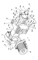
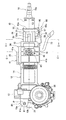
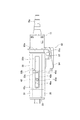
本発明の実施形態を、図1乃至図6にもとづいて説明する。図1は車両用ステアリング装置の斜視図、図2は図1のA矢視図、図3は図1のB−B線断面図、図4は図2のC−C線断面図、図5は図2のD−D線断面図、図6は図2からロアハウジングを除いた側面図、図7は図4の要部拡大図である。 An embodiment of the present invention will be described with reference to FIGS. 1 to 6. 1 is a perspective view of a steering apparatus for a vehicle, FIG. 2 is a cross-sectional view taken along an arrow A in FIG. 1, FIG. 3 is a cross-sectional view taken along the line BB in FIG. 2 is a cross-sectional view taken along the line D-D in FIG. 2, FIG. 6 is a side view in which the lower housing is removed from FIG. 2, and FIG.
図3に示すように、車両用ステアリング装置10はアッパーチューブ11を有し、このアッパーチューブ11は、ロアハウジング12に対し軸方向に進退可能に遊嵌されている。ロアハウジング12は鋳物で一体成形され、ロアハウジング12は、ギヤハウジング部13と、円筒部14と、円筒部14の軸線を挟んで一側に配置されるガイド部15(図1)とからなっている。ギヤハウジング部13に第1の中間軸20と第2に中間軸21が互いに軸方向にずらして同軸回りに回転可能に軸承されている。第1の中間軸20と第2の中間軸21は、トーションバー22を介して互いに回転連結され、第1の中間軸20と第2の中間軸21の相対回転量を検出するトルクセンサ23がギヤハウジング部13に設けられている。
As shown in FIG. 3, the
第2の中間軸21にはウォームホィールギヤ24が嵌合固定され、このウォームホィールギヤ24にウォームギヤ25が噛合している。ウォームギヤ25に図2で示す駆動モータ26の駆動軸が連結され、トルクセンサ23で検出されたトルクに応じて、駆動モータ26の力が図3で示すウォームギヤ25、ウォームホィールギヤ24を介して第2の中間軸21に伝えられるようになっている。
A
前記アッパーチューブ11と前記ロアハウジング12には、ステアリングシャフト16が回転可能に軸承され、このステアリングシャフト16は、アッパーチューブ11に回転可能に軸承されるアッパーシャフト16aと、ロアハウジング12の円筒部14に遊嵌されるロアシャフト16bとからなっている。ロアシャフト16bの一端はアッパーシャフト16aに軸方向に進退可能にかつ回転伝達可能にスプライン嵌合され、ロアシャフト16bの他端は第1の中間軸20に嵌合固定されている。ロアシャフト16bは第1の中間軸20とアッパーシャフト16aを介して間接的にロアハウジング12に回転可能に支持されている。アッパーシャフト16aの一端には運転手が操作する図略のハンドルが連結され、第2の中間軸21のハンドルと反対側の一端に図略のインターミディエイトシャフトが連結されている。
A
図2に示すように、前記ギヤハウジング部13はロア側支持機構80を介して図略の車両に旋回可能に支持され、前記アッパーチューブ11はアッパー側支持機構25を介して図略の車両にテレスコ及びチルト可能に支持されている。アッパー側支持機構25は、図略の車両に対してアッパーチューブ11をテレスコおよびチルト調整可能に案内支持する案内支持機構26と、テレスコおよびチルト調整後その位置でアッパーチューブ11を車両に対しロックするロック機構60とを備えている。
As shown in FIG. 2, the
前記ロア側支持機構80は、ギヤハウジング部13に一体形成された旋回連結部13aと、旋回連結部13aの取付け穴13bに嵌め込まれたブッシュ81と、ブッシュ81の連結穴81aに回転可能に嵌合された図略の軸支ピンと、軸支ピンを固定し車両に固定された図略の旋回ブラケットとからなっている。軸支ピンの軸線P回りにギヤハウジング部13が旋回可能に支持されている。
The lower-
前記案内支持機構26は、図4にも示すように、前記アッパーチューブ11の軸線を挟んで一側に配置され、アッパーチューブ11の外周に溶接等により固定された断面コの字形のガイドブラケット30と、アッパーチューブ11とガイドブラケット30間に配置されたコラプスプレート40と、車両に固定された取付けブラケット41と、取付けブラケット41とガイドブラケット30間とで挟持されるガイド部15とを有する。
As shown in FIG. 4, the
前記ガイドブラケット30は、一枚の板金から切り抜き、折り曲げ加工したもので、アッパーチューブ11側へ延びる一対の第1の板部31、32と、一対の第1の板部31、32に対し傾斜した案内部34、35と、案内部34、35を互いに連結する連結部33とを有する。一対の第1の板部31、32の一端がアッパーチューブ11に溶接等により固定されている。案内部34、35は、一対の第1の板部31、32と連結部33間に設けられ、双方に対し傾斜している。図6に示すように、連結部33にはアッパーチューブ11の軸方向にコラプス用案内溝33aが形成され、また連結部33にはコラプス用案内溝33aに繋がるコラプス突起形成用溝33bが略L字状に形成されている。コラプス突起形成用溝33bによってコラプス用突起33cが形成され、コラプス用突起33cの一部がコラプス用案内溝33aへ突出している。
The
前記コラプスプレート40は、鋳物により一体成形された略板状もので、コラプスプレート40には、アッパーチューブ11の軸方向にテレスコ溝40aが形成されている。コラプスプレート40のテレスコ溝40aの周囲には、コラプス用案内溝33aに係合するボス部40bが一体形成され、ボス部40bのインターミディエイトシャフト側の端40cは、コラプス用案内溝33aのインターミディエイトシャフト側の端に当接し、ボス部40bのハンドル側の端40dは、コラプス用突起33cに当接している。2次衝突が発生するまでは、コラプスプレート40は図6に示す位置に保持され、テレスコ調整時にコラプスプレート40とともにガイドブラケット30が移動するようになっている。2次衝突が発生すると、コラプス用突起33cはコラプス突起形成用溝33b側へ折り曲げられ、ボス部40bはコラプス突起形成用溝33bに沿ってハンドル側へ移動するようになっている。
The
図1に示すように、前記取付けブラケット41は鋳物により一体成形され、取付けブラケット41は、水平方向に延び、一端が車両に固定される取付け部41aと、取付け部41aの他端に一体的に成形されたボックス状のボックス部41bとからなっている。図4に示すように、ボックス部41bには、前記軸線P(図2)回りにチルト溝41cが形成されている。
As shown in FIG. 1, the mounting
図7に示すように、前記ロック機構60は、締付けボルト63と、この締付けボルト63に嵌合された一対の板カム71、72と、板カム71と一体回転するレバー73と、締付けボルト63のネジ部63dに螺合されたナット74とからなっている。締付けボルト63は、軸部63aと、軸部63aの一端に半径方向に突出する形で形成された頭部63bと、軸部63bの他端に形成されたネジ部63dとを有する。前記軸部63a、頭部63b、ネジ部63dは、切削等により一体的に形成されている。
As shown in FIG. 7, the
一対の板カム71、72は、互いに向かい合う端面にカム部を有し、板カム71、72を互いに相対回転させるとカム部によって、板カム71、72が互いに軸方向に接近離間するようになっている。板カム72のボス部72aがチルト溝41cに挿入され、板カム72のフランジ部72bがアジャストブラケット40の第1の板部41の図略の規制溝に係合することにより、板カム72の回転が規制されている。
The pair of
前記ガイド部15は、略コ字形状の断面形状を有し、ガイドブラケット30を挟み込むような形で配置される突出部15a、15bと、突出部15a、15bを繋ぐプレート部15cとからなっている。各突出部15a、15bには、ガイドブラケット30をアッパーチューブ11の軸方向に案内支持するレール65、66が設けられている。プレート15cには、前記締付けボルト63を挿通する挿通穴15dが形成されている。
The
図3及び図5に示すように、アッパーチューブ11の外周には、アッパーシャフト16aの回転をロックあるいはアンロックするステアリングロック装置90が固定されている。このステアリングロック装置90は、アッパーシャフト16aに圧入固定されたカラー91と、カラー91のキー溝91aに回転方向に係合するシリンダー92と、このシリンダー92をキー溝91aに対し挿入離脱させるシリンダー用アクチュエータ93と、前記シリンダー92を進退可能に案内するとともに、アッパーチューブ11の軸線を挟んで他側に配置されるロックハウジング94と、このロックハウジング94とでアッパーチューブ11を挟み込むような形で配置されるとともに、アッパーチューブ11の軸線を挟んで一側に配置されるロックブラケット部95と、ロックブラケット部95をロックハウジング94に固定する固定装置96とからなっている。前記カラー91には、円周方向に複数のキー溝91aが等間隔に形成されている。
As shown in FIGS. 3 and 5, a
シリンダー用アクチュエータ93は、ロックハウジング94に固定された図略のモータと、モータの駆動軸に一体的に連結されたウォームギヤ93aと、ウォームギヤ93aに噛合するウォームホィールギヤ93bと、ウォームホィールギヤ93bと一体回転可能に連結され、ロックハウジング94に回転可能に軸承された回転軸93cと、回転軸93cに形成されたおねじ部93dと、このおねじ部93dに螺合するめねじ部93eと、めねじ部93eが形成され、ロックハウジング94に移動可能に案内支持された可動部材93fと、シリンダー92と可動部材93f間に配置された押圧スプリング93gとからなっている。
The
ロックハウジング94のアッパーチューブ11側の面には、アッパーチューブ11の外周に当接する断面円弧状の当接面94cが形成され、ロックハウジング94のアッパーチューブ11側の面には、当接面94cよりもアッパーチューブ11側へ突出するような形でシリンダー92の周囲にボス部94dが形成されている。このボス部94が、アッパーチューブ11に形成された貫通穴11aに嵌合されている。ボス部94と貫通穴11aとの嵌合により、ロックハウジング94は、アッパーチューブ11に対し回転方向並びに軸方向の移動が阻止される。
A
シリンダー92は小径部92aを有し、この小径部92aは可動部材93fの図略の貫通穴に挿通されている。小径部92aの一端には図略のねじ部が形成されており、このねじ部にナット93hが螺合固定されている。シリンダー92の段部92bと可動部材93f間には押圧スプリング93gが介挿されている。
The
ロックブラケット部95は、アッパーチューブ11の外周に当接する円弧部95aと、円弧部95aの一端にループ状に折り曲げ成形されたループ部95bと、円弧部95aの他端に形成され、ロックハウジング94に当接可能な当接部95cとからなっている。当接部95cには後述する固定ボルト97を挿通する挿通穴95dが形成されている。ロックハウジング94の一部を覆うような形でロックカバー94aがロックハウジング94に固定されている。ロックハウジング94には挿通穴95dに対応する位置にねじ穴94bが形成されている。
The
図1および図5に示すように、前記固定装置96は、ロックカバー94aに軸支固定された軸支ピン96aと、軸支ピン96aを挿通するループ部95bと、ロックブラケット部95の挿通穴95dを介してロックハウジング94のねじ穴94bに螺合される固定ボルト97とからなっている。軸支ピン96aは、一端に半径方向に突出した頭部96bを有し、ロックブラケット部95とループ部95bを挿通した後、軸支ピン96aの他端に図略の止めピンあるいは止め輪を取付けることにより、ロックカバー94aに対する軸支ピン96aの抜けが防止される。
As shown in FIGS. 1 and 5, the fixing
まず、上述した構成にもとづいて、ステアリングロック装置90をアッパーチューブ11に取付ける動作について説明する。図5に示すように、アッパーチューブ11の外周にロックハウジング94の当接面94cを当接させるとともに、ボス部94dを貫通穴11aに嵌合させる。ロックカバー94aとループ部95bに軸支ピン95aを挿通し、軸支ピン96の他端に図略の止めピンあるいは止め輪を取付ける。挿通穴95dに固定ボルト97を挿入し、固定ボルト97をねじ穴94bに螺合させる。こうして、ロックブラケット部95とロックハウジング94とでアッパーチューブ11を挟み込むような形で、ロックハウジング94がアッパーチューブ11に固定される。
First, the operation of attaching the
次に、ステアリングロック装置90によるアッパーシャフト16aの回転ロック動作について説明する。図略のモータによって、ウォームギヤ93aをロック方向に回転させ、ウォームギヤ93aの回転は、ウォームホィールギヤ93b、おねじ部93d、めねじ部93eを介して可動部材93fの軸動に変換される。可動部材93fがアッパーチューブ11側へ軸動し、押圧スプリング93gを介してシリンダー92をキー溝91aに係入する方向に押圧する。これでもキー溝91aにシリンダー92が係入していないときは、ハンドルを介してアッパーシャフト16aを回転させると、キー溝91aにシリンダー92が係入してアッパーシャフト16aの回転がロックされる。
Next, the rotation lock operation of the
逆に、ステアリングロック装置90によるアッパーシャフト16aの回転ロックを解除する場合は、図略のモータによって、ウォームギヤ93aをアンロック方向に回転させる。可動部材93fがアッパーチューブ11と反対側へ軸動し、ナット93hを介してシリンダー92をアッパーチューブ11と反対側へ後退させる。キー溝91aに対するシリンダー92の係合が解除され、アッパーシャフト16aを回転させることが出来る。
On the contrary, when the rotation lock of the
ロックブラケット部95は、ガイドブラケット30と一体成形されているので、部品点数を少なくすることが出来る。また、アッパーチューブ11をロックブラケット部95とロックハウジング94とで挟み込んでロックハウジング94をアッパーチューブ11に固定する構造を採っているため、溶接等で固定する従来に比べて容易に固定できる。
Since the
さらに、運転手の体格、姿勢に合わせて、アッパーチューブ11をテレスコおよびチルトさせる動作について説明する。図7に示すように、レバー73をロック機構60が緩む方向に回すと、板カム71、72同士が軸方向に互いに接近し、頭部63bを介してコラプスプレート40、ガイドブラケット30をガイド部15に押し付ける力が弱まる。かかる状態で、テレスコ調整したい場合は、運転手はアッパーチューブ11とともにハンドルを引っ張るか押す。ガイドブラケット30がレール65、66に沿って移動するとともに、テレスコ溝40aに沿って軸部63aが移動する。また、チルト調整したい場合は、軸線P回りにロアハウジング12とともにアッパーチューブ11を軸線P回りに旋回させる。板カム72のボス部72aがチルト溝41cに沿って移動する。
Furthermore, the operation | movement which telescopically and tilts the
アッパーチューブ11を任意のテレスコおよびチルト(旋回)位置へ移動させた後、レバー73をロック機構60が締まる方向に回すと、板カム71、72同士が軸方向に互いに離間し、頭部63bを介してコラプスプレート40、ガイドブラケット30をガイド部15に押し付ける力が強くなり、ガイド部15をボックス部41bに押付ける力が強くなる。こうしてアッパーチューブ11は、取付けブラケット41に対し、任意のテレスコおよびチルト位置にロックされる。
After the
このように、取付けブラケット41、ロックハウジング94、コラプスプレート40が鋳物で作られ、ガイド部15をボックス部41bに一方向に押付け、コラプスプレート40、ガイドブラケット30をガイド部15に一方向に押付ける構造を採っているので、ディスタンスブラケットとアジャストブラケットを板金で製作し、アッパーチューブに固定された断面コ字形状のディスタンスブラケットを車両に固定された断面コ字形状のアジャストブラケットで両側から挟み込む従来に比べて、ハンドルを操作したときに、ブラケット同士の干渉音が少ない。
In this manner, the mounting
本発明は、こうした実施形態に何等限定されるものではなく、本発明の要旨を逸脱しない範囲において、種々なる態様で実施し得ることは勿論である。 The present invention is not limited to these embodiments, and can of course be implemented in various modes without departing from the gist of the present invention.
上述した実施形態は、シリンダー92と可動部材93fを平行に設け、おねじ部93dとめねじ部93eによって回転を軸動に変換した。他の実施形態として、シリンダー92の外周に円筒状の可動部材93fを同軸に設け、シリンダー92と可動部材93f間に設けたカム機構によって回転を軸動に変換しても良い。
In the embodiment described above, the
11:アッパーチューブ、12:ロアハウジング、15:ガイド部、16a:アッパーシャフト、16b:ロアシャフト、25:アッパー側支持機構、26:案内支持機構、30:ガイドブラケット、60:ロック機構、80:ロア側支持機構、90:ステアリングロック装置、91a:キー溝、92:シリンダー、93:シリンダー用アクチュエータ、94:ロックハウジング、95:ロックブラケット部 11: Upper tube, 12: Lower housing, 15: Guide part, 16a: Upper shaft, 16b: Lower shaft, 25: Upper side support mechanism, 26: Guide support mechanism, 30: Guide bracket, 60: Lock mechanism, 80: Lower side support mechanism, 90: steering lock device, 91a: keyway, 92: cylinder, 93: actuator for cylinder, 94: lock housing, 95: lock bracket
Claims (1)
前記ロックハウジングは前記アッパーチューブの軸線を挟んで他側に配置され、前記ロックブラケット部は前記アッパーチューブの軸線を挟んで一側に配置され、
前記ロックハウジング、前記ロックブラケット部および前記アッパーチューブをそれぞれ別体で構成し、前記アッパーチューブを前記ロックハウジングおよび前記ロックブラケット部で挟み込むことにより、前記アッパーチューブに前記ロックハウジングおよび前記ロックブラケット部を取付け、
前記案内支持機構は、前記アッパーチューブの軸線を挟んで一側に配置され、前記アッパーチューブに固定されたガイドブラケットと、前記ロアハウジングに設けられ、前記ガイドブラケットを前記アッパーチューブの軸方向に案内支持するガイド部とからなり、
前記ガイドブラケットと前記ロックブラケット部を一体成形したことを特徴とする車両用ステアリング装置。
A lower shaft, an upper shaft connected to the lower shaft so as to be capable of axial movement and rotation transmission, an upper tube that rotatably supports the upper shaft, and a lower housing that rotatably supports the lower shaft; A lower side support mechanism that supports the lower housing with respect to the vehicle, an upper side support mechanism that supports the upper tube with respect to the vehicle, and a steering lock device that locks or unlocks rotation of the upper shaft, The upper side support mechanism includes a guide support mechanism that guides and supports the upper tube with respect to the lower housing in the axial direction of the upper tube, and an axial position of the upper tube with respect to the lower housing, To connect the upper tube to the vehicle. The steering lock device includes a key groove provided in the upper shaft, a cylinder that engages the key groove in the rotational direction, and a cylinder that inserts and removes the cylinder from the key groove. In a vehicle steering apparatus comprising an actuator, a lock housing that guides the cylinder so as to be able to advance and retreat, and a lock bracket portion that is arranged in such a manner that the upper tube is sandwiched between the lock housing,
The lock housing is disposed on the other side across the axis of the upper tube, and the lock bracket portion is disposed on one side across the axis of the upper tube,
The lock housing, the lock bracket portion, and the upper tube are configured separately, and the upper tube is sandwiched between the lock housing and the lock bracket portion, whereby the lock housing and the lock bracket portion are inserted into the upper tube. Installation,
The guide support mechanism is disposed on one side across the axis of the upper tube , and is provided in a guide bracket fixed to the upper tube and the lower housing, and guides the guide bracket in the axial direction of the upper tube. It consists of a guide part to support,
A steering apparatus for a vehicle, wherein the guide bracket and the lock bracket portion are integrally formed.
Priority Applications (3)
| Application Number | Priority Date | Filing Date | Title |
|---|---|---|---|
| JP2011054992A JP5750949B2 (en) | 2011-03-14 | 2011-03-14 | Vehicle steering device |
| US13/413,088 US8733201B2 (en) | 2011-03-14 | 2012-03-06 | Steering apparatus for vehicle |
| EP12158631.7A EP2500241B1 (en) | 2011-03-14 | 2012-03-08 | Steering apparatus for vehicle |
Applications Claiming Priority (1)
| Application Number | Priority Date | Filing Date | Title |
|---|---|---|---|
| JP2011054992A JP5750949B2 (en) | 2011-03-14 | 2011-03-14 | Vehicle steering device |
Publications (2)
| Publication Number | Publication Date |
|---|---|
| JP2012188055A JP2012188055A (en) | 2012-10-04 |
| JP5750949B2 true JP5750949B2 (en) | 2015-07-22 |
Family
ID=45894112
Family Applications (1)
| Application Number | Title | Priority Date | Filing Date |
|---|---|---|---|
| JP2011054992A Active JP5750949B2 (en) | 2011-03-14 | 2011-03-14 | Vehicle steering device |
Country Status (3)
| Country | Link |
|---|---|
| US (1) | US8733201B2 (en) |
| EP (1) | EP2500241B1 (en) |
| JP (1) | JP5750949B2 (en) |
Cited By (1)
| Publication number | Priority date | Publication date | Assignee | Title |
|---|---|---|---|---|
| US10661819B2 (en) * | 2015-08-26 | 2020-05-26 | Thyssenkrupp Presta Ag | Motor-adjustable steering column for a motor vehicle |
Families Citing this family (22)
| Publication number | Priority date | Publication date | Assignee | Title |
|---|---|---|---|---|
| JP5999767B2 (en) * | 2012-12-27 | 2016-09-28 | 株式会社ジェイテクト | Steering device |
| FR3025161B1 (en) * | 2014-08-29 | 2016-12-30 | Zf Systemes De Direction Nacam Sas | ADJUSTABLE STEERING COLUMN MECHANISM WITH ANTI-THEFT LOCK |
| JP2016055689A (en) * | 2014-09-08 | 2016-04-21 | 富士機工株式会社 | Electric type steering column device |
| CN104554421A (en) * | 2014-12-30 | 2015-04-29 | 耐世特汽车系统(苏州)有限公司 | Steering column protecting pipe |
| KR102190492B1 (en) * | 2015-03-02 | 2020-12-14 | 주식회사 만도 | Steering Column for Vehicle |
| US10343706B2 (en) | 2015-06-11 | 2019-07-09 | Steering Solutions Ip Holding Corporation | Retractable steering column system, vehicle having the same, and method |
| US11560169B2 (en) | 2015-06-11 | 2023-01-24 | Steering Solutions Ip Holding Corporation | Retractable steering column system and method |
| CN106256651B (en) | 2015-06-16 | 2019-06-04 | 操纵技术Ip控股公司 | Regracting steering column assembly and method |
| DE102016111473A1 (en) | 2015-06-25 | 2016-12-29 | Steering Solutions Ip Holding Corporation | STATIONARY STEERING WHEEL ASSEMBLY AND METHOD |
| DE102016205378B3 (en) * | 2016-03-31 | 2017-05-11 | Thyssenkrupp Ag | Steering column for a motor vehicle |
| US10421476B2 (en) | 2016-06-21 | 2019-09-24 | Steering Solutions Ip Holding Corporation | Self-locking telescope actuator of a steering column assembly |
| US10457313B2 (en) | 2016-06-28 | 2019-10-29 | Steering Solutions Ip Holding Corporation | ADAS wheel locking device |
| US10363958B2 (en) | 2016-07-26 | 2019-07-30 | Steering Solutions Ip Holding Corporation | Electric power steering mode determination and transitioning |
| US10189496B2 (en) | 2016-08-22 | 2019-01-29 | Steering Solutions Ip Holding Corporation | Steering assembly having a telescope drive lock assembly |
| US20180086378A1 (en) * | 2016-09-27 | 2018-03-29 | Steering Solutions Ip Holding Corporation | Position detection system for a retractable steering column |
| US10351160B2 (en) | 2016-11-30 | 2019-07-16 | Steering Solutions Ip Holding Corporation | Steering column assembly having a sensor assembly |
| US10370022B2 (en) | 2017-02-13 | 2019-08-06 | Steering Solutions Ip Holding Corporation | Steering column assembly for autonomous vehicle |
| US10385930B2 (en) | 2017-02-21 | 2019-08-20 | Steering Solutions Ip Holding Corporation | Ball coupling assembly for steering column assembly |
| DE102017120669A1 (en) * | 2017-09-07 | 2019-03-07 | Trw Automotive Gmbh | Steering column assembly for a motor vehicle and steering system |
| US10974756B2 (en) | 2018-07-31 | 2021-04-13 | Steering Solutions Ip Holding Corporation | Clutch device latching system and method |
| DE102020201703A1 (en) * | 2020-02-11 | 2021-08-12 | Thyssenkrupp Ag | Steering column for a motor vehicle |
| KR20210108014A (en) * | 2020-02-25 | 2021-09-02 | 주식회사 만도 | Steering column for vehicle |
Family Cites Families (17)
| Publication number | Priority date | Publication date | Assignee | Title |
|---|---|---|---|---|
| DE4038010A1 (en) * | 1990-11-29 | 1992-06-04 | Stabilus Gmbh | HYDRAULICALLY ADJUSTABLE STEERING COLUMN |
| US5485376A (en) * | 1991-06-14 | 1996-01-16 | Nissan Motor Co., Ltd. | Steering wheel posture control system |
| DE4436091C1 (en) | 1994-10-10 | 1996-02-22 | Kostal Leopold Gmbh & Co Kg | Anti-theft steering system for vehicle |
| US5718132A (en) * | 1996-08-05 | 1998-02-17 | General Motors Corporation | Anti-theft steering shaft lock |
| US5992191A (en) * | 1998-04-06 | 1999-11-30 | Nickeas; Mark | Anti-theft device for motor vehicles |
| DE20103203U1 (en) * | 2001-02-23 | 2001-07-05 | Huf Huelsbeck & Fuerst Gmbh | Device for occasionally locking a steering column in a vehicle |
| ES2265513T3 (en) * | 2001-10-23 | 2007-02-16 | Trw Lucas Varity Electric Steering Limited | VEHICLE ADDRESS SET. |
| JP2003327134A (en) * | 2002-05-09 | 2003-11-19 | Koyo Seiko Co Ltd | Shock-absorbing type steering gear |
| JP2005297645A (en) * | 2004-04-07 | 2005-10-27 | Tokai Rika Co Ltd | Steering lock device |
| JP2007099260A (en) * | 2005-07-11 | 2007-04-19 | Nsk Ltd | Steering device |
| JP4483931B2 (en) * | 2007-11-08 | 2010-06-16 | トヨタ自動車株式会社 | Steering device |
| US8596160B2 (en) * | 2007-11-13 | 2013-12-03 | Nsk Ltd. | Steering apparatus |
| JP5358932B2 (en) * | 2007-11-13 | 2013-12-04 | 日本精工株式会社 | Steering device |
| JP5229551B2 (en) * | 2008-08-29 | 2013-07-03 | 株式会社ジェイテクト | Vehicle steering system |
| FR2937598B1 (en) | 2008-10-23 | 2011-09-23 | Valeo Securite Habitacle | ANTI-THEFT DEVICE FOR THE STEERING COLUMN OF A MOTOR VEHICLE |
| CN102256858B (en) | 2008-12-19 | 2014-12-10 | C.劳勃.汉默斯坦两合有限公司 | Length-adjustable steering actuation unit for a motor vehicle with a support and a steering column |
| US8272291B2 (en) * | 2010-01-15 | 2012-09-25 | Samuel Fasone | Steering column locking device |
-
2011
- 2011-03-14 JP JP2011054992A patent/JP5750949B2/en active Active
-
2012
- 2012-03-06 US US13/413,088 patent/US8733201B2/en active Active
- 2012-03-08 EP EP12158631.7A patent/EP2500241B1/en active Active
Cited By (1)
| Publication number | Priority date | Publication date | Assignee | Title |
|---|---|---|---|---|
| US10661819B2 (en) * | 2015-08-26 | 2020-05-26 | Thyssenkrupp Presta Ag | Motor-adjustable steering column for a motor vehicle |
Also Published As
| Publication number | Publication date |
|---|---|
| US8733201B2 (en) | 2014-05-27 |
| EP2500241A3 (en) | 2013-03-06 |
| JP2012188055A (en) | 2012-10-04 |
| EP2500241A2 (en) | 2012-09-19 |
| EP2500241B1 (en) | 2014-10-29 |
| US20120234127A1 (en) | 2012-09-20 |
Similar Documents
| Publication | Publication Date | Title |
|---|---|---|
| JP5750949B2 (en) | Vehicle steering device | |
| JP5321688B2 (en) | Steering device | |
| JP4932388B2 (en) | Movable steering device | |
| JP4938386B2 (en) | Movable steering device | |
| JP4483914B2 (en) | Steering column device | |
| JP5338922B2 (en) | Steering device | |
| US11148703B2 (en) | Support bracket for steering apparatus and steering apparatus | |
| JP2003276614A (en) | Steering device | |
| JP5076673B2 (en) | Steering device | |
| JP2008174105A (en) | Steering device | |
| JP5086724B2 (en) | Steering column device | |
| JP2007083936A (en) | Steering device for vehicle | |
| JP4483931B2 (en) | Steering device | |
| JP2008105610A (en) | Steering device | |
| JP5641057B2 (en) | Steering device | |
| JP5019925B2 (en) | Steering column device | |
| JP4835017B2 (en) | Steering device | |
| JP4470302B2 (en) | Vehicle steering device | |
| JP2005138825A (en) | Steering column device | |
| JP2008126750A (en) | Steering device | |
| JP6759746B2 (en) | Steering device | |
| JP2010105521A (en) | Vehicular steering device | |
| JP2008006839A (en) | Telescopic steering device | |
| JP2004136870A (en) | Tilt steering device | |
| JP2010076690A (en) | Steering column device |
Legal Events
| Date | Code | Title | Description |
|---|---|---|---|
| A621 | Written request for application examination |
Free format text: JAPANESE INTERMEDIATE CODE: A621 Effective date: 20140218 |
|
| A977 | Report on retrieval |
Free format text: JAPANESE INTERMEDIATE CODE: A971007 Effective date: 20140814 |
|
| A131 | Notification of reasons for refusal |
Free format text: JAPANESE INTERMEDIATE CODE: A131 Effective date: 20141007 |
|
| A521 | Request for written amendment filed |
Free format text: JAPANESE INTERMEDIATE CODE: A523 Effective date: 20141126 |
|
| TRDD | Decision of grant or rejection written | ||
| A01 | Written decision to grant a patent or to grant a registration (utility model) |
Free format text: JAPANESE INTERMEDIATE CODE: A01 Effective date: 20150421 |
|
| A61 | First payment of annual fees (during grant procedure) |
Free format text: JAPANESE INTERMEDIATE CODE: A61 Effective date: 20150504 |
|
| R150 | Certificate of patent or registration of utility model |
Ref document number: 5750949 Country of ref document: JP Free format text: JAPANESE INTERMEDIATE CODE: R150 |