US9319135B2 - Light powered communication systems and methods of using the same - Google Patents
Light powered communication systems and methods of using the same Download PDFInfo
- Publication number
- US9319135B2 US9319135B2 US13/981,162 US201213981162A US9319135B2 US 9319135 B2 US9319135 B2 US 9319135B2 US 201213981162 A US201213981162 A US 201213981162A US 9319135 B2 US9319135 B2 US 9319135B2
- Authority
- US
- United States
- Prior art keywords
- remote communication
- communication systems
- control center
- communication system
- powered
- Prior art date
- Legal status (The legal status is an assumption and is not a legal conclusion. Google has not performed a legal analysis and makes no representation as to the accuracy of the status listed.)
- Active, expires
Links
- 230000006854 communication Effects 0.000 title claims abstract description 266
- 238000004891 communication Methods 0.000 title claims abstract description 266
- 238000000034 method Methods 0.000 title claims description 14
- 230000003287 optical effect Effects 0.000 claims abstract description 84
- 239000000835 fiber Substances 0.000 claims abstract description 28
- 230000005236 sound signal Effects 0.000 claims description 15
- 230000007175 bidirectional communication Effects 0.000 claims description 3
- 239000013307 optical fiber Substances 0.000 description 26
- 238000001228 spectrum Methods 0.000 description 12
- 238000010586 diagram Methods 0.000 description 11
- 230000003595 spectral effect Effects 0.000 description 8
- 230000003750 conditioning effect Effects 0.000 description 4
- 230000001934 delay Effects 0.000 description 4
- 230000008859 change Effects 0.000 description 3
- 238000013500 data storage Methods 0.000 description 3
- 230000008569 process Effects 0.000 description 2
- 230000035945 sensitivity Effects 0.000 description 2
- RYGMFSIKBFXOCR-UHFFFAOYSA-N Copper Chemical compound [Cu] RYGMFSIKBFXOCR-UHFFFAOYSA-N 0.000 description 1
- 230000003321 amplification Effects 0.000 description 1
- 238000004458 analytical method Methods 0.000 description 1
- 238000013459 approach Methods 0.000 description 1
- 230000008901 benefit Effects 0.000 description 1
- 230000005540 biological transmission Effects 0.000 description 1
- 239000003245 coal Substances 0.000 description 1
- 229910052802 copper Inorganic materials 0.000 description 1
- 239000010949 copper Substances 0.000 description 1
- 230000007812 deficiency Effects 0.000 description 1
- 230000000881 depressing effect Effects 0.000 description 1
- 230000000994 depressogenic effect Effects 0.000 description 1
- 230000000694 effects Effects 0.000 description 1
- 230000005611 electricity Effects 0.000 description 1
- 238000001914 filtration Methods 0.000 description 1
- 238000005286 illumination Methods 0.000 description 1
- 238000002347 injection Methods 0.000 description 1
- 239000007924 injection Substances 0.000 description 1
- 238000009434 installation Methods 0.000 description 1
- 238000012423 maintenance Methods 0.000 description 1
- 238000004519 manufacturing process Methods 0.000 description 1
- 239000000463 material Substances 0.000 description 1
- 239000012528 membrane Substances 0.000 description 1
- 239000002184 metal Substances 0.000 description 1
- 229910052751 metal Inorganic materials 0.000 description 1
- 238000012986 modification Methods 0.000 description 1
- 230000004048 modification Effects 0.000 description 1
- 238000003199 nucleic acid amplification method Methods 0.000 description 1
- 238000012545 processing Methods 0.000 description 1
- 230000000007 visual effect Effects 0.000 description 1
Images


Classifications
-
- H—ELECTRICITY
- H04—ELECTRIC COMMUNICATION TECHNIQUE
- H04B—TRANSMISSION
- H04B10/00—Transmission systems employing electromagnetic waves other than radio-waves, e.g. infrared, visible or ultraviolet light, or employing corpuscular radiation, e.g. quantum communication
- H04B10/25—Arrangements specific to fibre transmission
- H04B10/2589—Bidirectional transmission
-
- H04B10/2503—
-
- H—ELECTRICITY
- H04—ELECTRIC COMMUNICATION TECHNIQUE
- H04B—TRANSMISSION
- H04B10/00—Transmission systems employing electromagnetic waves other than radio-waves, e.g. infrared, visible or ultraviolet light, or employing corpuscular radiation, e.g. quantum communication
- H04B10/11—Arrangements specific to free-space transmission, i.e. transmission through air or vacuum
- H04B10/114—Indoor or close-range type systems
- H04B10/1143—Bidirectional transmission
Definitions
- This invention relates generally to the field of communication systems and, more particularly, to light powered communication systems and methods of using the same.
- Communication systems e.g., telephone communication systems
- industrial and military applications rely on communication systems for efficiency and safety.
- Many currently used communication systems are conventional copper telephone systems with heavy cables and strong sensitivity to electrical interference.
- typical conventional communication systems require electrical power at each location in the communication chain. In the event of a power failure the usefulness of such systems may be limited.
- Back-up power sources e.g., battery systems, uninterruptible power supplies, etc.
- the cost of installation and maintenance of such back-up power sources at a plurality of locations may be cost-prohibitive.
- the present invention provides, according to an exemplary embodiment, a light powered communication system.
- the light powered communication system includes an audio control center having at least one optical source and at least one optical receiver.
- the light powered communication system also includes a plurality of optically powered remote communication systems (located remote from the audio control center), each of the optically powered remote communication systems being configured to receive an optical signal from the audio control center.
- the light powered communication system also includes at least one length of fiber optic cable between the audio control center and each of the optically powered remote communication systems.
- a method of operating a light powered communication system includes the steps of: (a) receiving an audio signal at one of a plurality of remote communication systems of the optically powered communication system; (b) transmitting an optical signal representative of the audio signal from the one of the plurality of remote communication systems to an audio control center of the optically powered communication system; (c) transmitting another optical signal representative of the audio signal to at least one other of the plurality of remote communication systems; and (d) converting the another optical signal to an audio output at the at least one other of the plurality of remote communication systems.
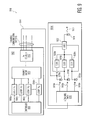
- FIG. 1 is a block diagram of a light powered communication system in accordance with an exemplary embodiment of the present invention
- FIG. 2A is a block diagram illustrating elements of another light powered communication system in accordance with an exemplary embodiment of the present invention
- FIG. 2B is a block diagram of a transducer which may be used in connection with a microphone of a light powered communication system in accordance with an exemplary embodiment of the present invention
- FIG. 3 is a block diagram illustrating additional elements of the light powered communication system of FIG. 2A ;
- FIG. 4 is a block diagram illustrating additional elements of the light powered communication system of FIG. 2A ;
- FIG. 5 is a block diagram illustrating elements of yet another light powered communication system in accordance with an exemplary embodiment of the present invention.
- FIG. 6 is a block diagram illustrating elements of yet another light powered communication system in accordance with an exemplary embodiment of the present invention.
- FIG. 7 is a block diagram illustrating elements of yet another light powered communication system in accordance with an exemplary embodiment of the present invention.
- FIG. 8A is a spectral plot illustrating a spectrum of a phase carrier applied to the output of a light source in accordance with an exemplary embodiment of the present invention
- FIG. 8B is a spectral plot illustrating a spectrum of a signal introduced at a microphone in accordance with an exemplary embodiment of the present invention.
- FIG. 8C is a spectral plot illustrating a modulated voice signal that is returned to a demodulator in an audio control center prior to signal demodulation in accordance with an exemplary embodiment of the present invention
- FIG. 8D is a spectral plot illustrating a spectrum of the returned signal of FIG. 8C after demodulation in accordance with an exemplary embodiment of the present invention
- FIG. 8E is a spectral plot illustrating a spectrum of the demodulated output signal of FIG. 8D after further signal conditioning in accordance with an exemplary embodiment of the present invention.
- FIG. 9 is a block diagram illustrating elements of yet another light powered communication system in accordance with an exemplary embodiment of the present invention.
- a light powered communication system (e.g., a light powered phone system) is provided, wherein a number of users can communicate via a series of optical communication channels.
- the light powered communication system includes an audio control center and a plurality of remote communication systems. Bi-directional communications between the audio control center and the remote communication systems are optically powered; therefore, the communications may be completed without external electrical power at the remote communication systems.
- Each of the remote communication systems includes an optically driven listening device (e.g., an earpiece, a speaker, etc.) and a microphone (e.g., a fiber optic interferometer).
- the audio control center may serve several functions including: (a) providing light for, and demodulating signals from, each of the microphones (see, e.g., FIG. 2A ); (b) retransmitting voice signals from a remote communication system to a desired user or users (see, e.g., FIGS. 3 and 7 ); (c) interpreting optical signals from at least one remote optical channel selector at each remote communication system that specifies whether each user (at a respective remote communication system) desires to communicate in a party line mode, or whether the user has selected other users (at specific remote communication systems) for communications (see, e.g., FIGS. 4-6 ); and (d) providing an annunciation at a remote communication system to alert a user of an incoming communication (see, e.g., FIG. 9 ).
- FIG. 1 illustrates a light powered communication system 100 (e.g., light powered phone system 100 ).
- System 100 includes an audio control center 102 and a plurality of remote communication systems 104 a , 104 b , 104 c , . . . , and 104 n .
- Each of remote communication systems 104 a , 104 b , 104 c , . . . , and 104 n is connected to audio control center 102 through a respective fiber optic cable 106 a , 106 b , 106 c , . . .
- Each of remote communication systems 104 a , 104 b , 104 c , . . . , and 104 n includes optically powered elements connected to audio control center 102 .
- each remote communication system 104 a , 104 b , 104 c , . . . , and 104 n includes: a respective enclosure 101 a , 101 b , 101 c , . . . , 101 n ; a respective annunciator 103 a , 103 b , 103 c , . . .
- a respective optically powered headset 104 a 1 , 104 b 1 , 104 c 1 , . . . , 104 n 1 (each including a respective microphone and earpiece); and a respective remote control communication selector 104 a 2 , 104 b 2 , 104 c 2 , . . . , 104 n 2 (where each communication selector allows a user to determine which other user(s) with whom to communicate).
- the numerous remote communication systems 104 a , 104 b , 104 c , . . . , and 104 n may be distributed throughout a location (e.g., a manufacturing plant, a vessel/ship, a mine such as a coal or metal mine, etc.) remote from audio control center 102 .
- Light powered communication/phone system 100 of FIG. 1 may have many different implementations, with varying elements and configurations.
- FIGS. 2A, 3, and 4 illustrate an exemplary light powered communication system 200 .
- Light powered communication system 200 includes audio control center 202 (elements of which are shown in each of FIGS. 2A, 3, and 4 ) and a plurality of remote communication systems 204 a , 204 b , 204 c , . . . , and 204 n.
- FIG. 2A illustrates a portion of light communication system 200 for processing “uplink” communications arriving at audio control center 202 from remote communication systems 204 a , 204 b , 204 c , . . . , and 204 n .
- a light source 210 e.g., a laser, etc.
- the signal is then divided at an optical coupler 214 , where portions of the divided signal are transmitted to respective remote communication systems 204 a , 204 b , 204 c , . . . , and 204 n via one or more optical fiber cables.
- a portion of the divided signal is transmitted from optical coupler 214 to an optical circulator 216 a at audio control center 202 .
- the signal leaves audio control center 202 along an optical fiber 206 a , then reaches remote communication system 204 a .
- Other portions of the divided signal from optical coupler 214 are transmitted through respective optical circulators 216 b , 216 c , and 216 n and then along respective optical fibers 206 b , 206 c , and 206 n , then reaching respective remote communication systems 204 b , 204 c , and 204 n .
- each remote communication system e.g., system 204 a
- an optical headset such as headset 104 a 1 shown in FIG. 1
- each split signal is divided between (1) a reference leg of an interferometer, and (2) a sensing leg of an interferometer within the respective remote communication system (e.g., where the sensing leg may include optical fiber captured within a thin flexible membrane, or wrapped around a thin-walled sealed tube, or other configurations).
- one portion of the signal from coupler 280 a is transmitted to a reference leg including acoustically insensitive coil of a fiber 282 a (e.g., wherein the deadened coil may be potted or substantially fixed in position) and a reflector 284 a .
- the other portion of the signal from coupler 280 a is transmitted to a sensing leg including a microphone 286 a .
- microphone 286 a is a Michelson type interferometer including a coil of fiber 288 a (in an acoustically sensitive arrangement) and a reflector 290 a.
- a user of remote communication system 204 a speaks into microphone 286 a in an effort to communicate with another user or users of light powered communication system 200 .
- Microphone 286 a converts vibrations from a voice of the speaking user (i.e., an audio signal) to a change in the optical phase of the light passing through microphone 286 a .
- FIG. 2A illustrates microphone 286 a included in a Michelson type interferometer, it is understood that other types of microphones (e.g., a linearized Sagnac type interferometer, or other configurations such as amplitude modulated acoustic transducers) are contemplated.
- 204 n includes: respective optical couplers 280 b , 280 c , . . . , 280 n ; respective reference legs including respective acoustically insensitive coils of fiber 282 b , 282 c , . . . , 282 n and respective reflectors 284 b , 284 c , . . . , 284 n ; and respective microphones 286 b (including coil of fiber 288 b and reflector 290 b ), 286 c (including coil of fiber 288 c and reflector 290 c ), . . . , 286 n (including coil of fiber 288 n and reflector 290 n ).
- each reference leg and microphone 286 a , 286 b , 286 c , . . . , 286 n is recombined (i.e., light from the reference leg and sensing leg is coherently recombined to convert the phase change to an intensity change) at respective optical coupler 280 a , 280 b , 280 c , . . . , 280 n , and then passes through respective optical circulator 216 a , 216 b , 216 c , . . .
- Each demodulator 218 a , 218 b , 218 c , . . . , 218 n (within audio control center 202 ) converts the light returning from a respective microphone (from a respective remote communication system) into an electrical signal, and then samples and demodulates (down converts) the electrical signal.
- controller 220 e.g., a microcontroller, a programmable logic controller, a digital signal processor, etc.
- controller 220 is used to filter, post process, and re-transmit the demodulated signals from demodulators 218 a , 218 b , 218 c , . . . , 218 n (the “downlink” communications).
- Each demodulator 218 a , 218 b , 218 c , . . . , 218 n is also used to send light (i.e., downlink communications) to certain remote communication systems, as selected by a user at the respective remote communication system using a remote control communication selector (also referred to as a remote optical channel selector), as described below.
- This signal retransmission (by way of controller 220 ) is to select remote communication systems 204 a , 204 b , 204 c , . . . , 204 n (as selected by users at systems 204 a , 204 b , 204 c , . . .
- Controller 220 is also connected to a data storage 222 which may be used for logging communications (e.g., regular communications, communications during drills or an emergency, etc.).
- Data storage 222 may be considered akin to a black box (e.g., a voice/data recorder) of an aircraft (e.g., recording all communication activity for later playback and analyses).
- multiple microphones may be multiplexed on a single cable fiber by combining laser wavelengths prior to phase modulation by use of a wavelength division multiplexer.
- the wavelengths may be separated for each microphone by use of an optical add/drop multiplexer (which also can be used to recombine the wavelengths for transit back to the audio control center).
- the multiple wavelength light may be split into individual wavelengths (one for each demodulator) by use of a wavelength division multiplexer.
- a wavelength division multiplexer which also can be used to recombine the wavelengths for transit back to the audio control center.
- microphones 286 a , 286 b , 286 c , . . . , 286 n include a coil of optical fiber (e.g., in an acoustically sensitive arrangement) to pick up speech by a user of the relevant remote communication system (such as in a Michelson or linear Sagnac type interferometer). It may be desired to include a transducer in the microphone along with the coil of optical fiber.
- FIG. 2B is a cross-sectional view of an exemplary transducer 300 .
- Transducer 300 includes a fixed mandrel 304 a , a spring 304 b , and a moveable mandrel 304 c (which tends to move along the y-axis shown in FIG.
- a mass 306 (which may envelope or surround at least a portion of fixed mandrel 304 a , spring 304 b , and/or moveable mandrel 304 c ) is secured to moveable mandrel 304 c .
- Fixed mandrel 304 a is rigidly attached to a body of interest 302 within a remote communication system (e.g., system 204 a ).
- a length of optical fiber 308 is wound around fixed mandrel 304 a and moveable mandrel 304 c .
- Optical fiber 308 is optically connected to (or continuous with) the length of optical fiber between the relevant optical coupler (e.g., coupler 280 a ) and the relevant reflector (e.g., reflector 290 a ).
- the relevant optical coupler e.g., coupler 280 a
- the relevant reflector e.g., reflector 290 a
- transducer 300 in the microphone (e.g., microphone 286 a )
- the optical fiber including the portion wound around fixed mandrel 304 a and moveable mandrel 304 c ) has improved sensitivity.
- alternative types of transducers may be utilized within the scope of the present invention.
- FIG. 3 is a block diagram of additional portions of light powered communication system 200 , and illustrates “downlink” communications from audio control center 202 to a remote communication system or systems (i.e., retransmission of uplink communications received at audio control center 202 described above).
- Electrical signals from either a microphone 230 (e.g., an electrical microphone for a user local to audio control center 202 ), or from controller 220 (i.e., from one of the uplink communications received by one of microphones 286 a , 286 b , 286 c , . . .
- a modulator 232 is modulated (e.g., such as through pulse width modulation, PWM) at a modulator 232 and are thereafter imposed on an injection current input 234 of a light source 236 (e.g., a laser 236 ).
- the signal from light source 236 is transmitted through an optical switch 238 (where a controller 240 operates switch 238 , thus determining along which optical fibers the voice modulated output from light source 236 is provided) and along a fiber optic cable from audio control center 202 to one or more remote communications systems 204 a , 204 b , 204 c , . . . , 204 n (e.g., to a headset at a given remote communication system or systems).
- FIG. 3 illustrates a modulated output signal transmitted through switch 238 to remote communication system 204 a .
- the light 244 received at remote communication system 204 a travels along a path 242 and is converted to an electric current via a photodetector 246 .
- This electric current is divided into an AC signal portion 248 and DC signal portion 254 .
- AC signal portion 248 is amplified at an amplifier 250 and is then provided as an audio output to a listening device 252 (e.g., ear phone 252 , speaker 252 , etc.).
- DC signal portion 254 is used to provide bias voltage(s) to the power circuit of amplifier 250 .
- a time division multiplexing or wavelength division multiplexed scheme may be employed for handling multiple simultaneous conversations.
- FIG. 3 illustrates the electrical current being divided into an AC signal portion and a DC signal portion
- the electrical current output from photodetector 246 may be transmitted to feed listening device 252 directly without being divided into the AC signal portion and a DC signal portion.
- remote communication systems 204 a , 240 b , 204 c , . . . , 204 n may have the opportunity to speak with various other users of the light communication system (e.g., in a party line mode where all uplink communications are heard at all remote communication systems simultaneously), or may select one or more users to speak with individually (e.g., where an optical switch is operated at the audio control center based on the selected users). If the user selects an individual user to speak with, there are various types of configurations which may be used to select that user.
- FIG. 4 is one such exemplary configuration of a remote communications channel selector using an interrogation system, and illustrates additional elements of light powered communication system 200 .
- FIG. 4 is a time-division multiplexing (TDM) implementation; however, a wavelength-division multiplexing (WDM) implementation is an exemplary alternative implementation.
- An electrical pulse source 258 provides voltage to drive a light source 256 (e.g., broadband light source 256 such as a SLED), and the light may be amplified at an amplifier 260 . Following amplifier 260 the light passes through an optical circulator 262 , and is divided at an optical coupler 264 .
- a light source 256 e.g., broadband light source 256 such as a SLED
- differing delays are applied to the divided light output from optical coupler 264 (i.e., a different delay is applied to each line going to a respective channel selector at a respective remote communication system) (i.e., a TDM operation).
- a different delay is applied to each line going to a respective channel selector at a respective remote communication system
- a TDM operation i.e., a TDM operation.
- light received at remote communication system 204 a is directed through an optical coupler 270 which divides the light.
- the divided light is directed to one of a plurality of optical paths 272 a , 272 b , 272 c , . . .
- each optical path includes a respective switch 274 a , 274 b , 274 c , . . . , 274 n , and a respective FBG (fiber Bragg grating) 276 a , 276 b , 276 c , . . . , 276 n where each FBG corresponds to a different light wavelength ⁇ a - ⁇ n .
- FBG fiber Bragg grating
- switches 274 a , 274 b , 274 c , . . . , 274 n may each be a button connected to an optical shutter that allows light to transmit to the respective FBG. The light then reflects back through optical coupler 270 and optical coupler 264 , to dense wavelength division multiplexer 268 (DWDM) at an interrogator 208 at audio control center 202 .
- DWDM dense wavelength division multiplexer 268
- a user at a given remote communication system e.g., system 204 a
- DWDM 268 at interrogator 208 separates the returned light from the various remote communication systems into different wavelengths (i.e., ⁇ a - ⁇ n ) each imposed upon a different optical photodetector 294 a , 294 b , 294 c , . . . , 294 n .
- each return pulse (with a spectrum that defines the listeners as selected by a user at a given remote communication system through operation of switches 274 a , 274 b , 274 c , . . . , 274 n ) arrives at interrogator 208 at a different time, but in a deterministic order such that interrogator 208 can determine which user (at a given remote communication system) has selected which set of listeners.
- , 292 n (at wavelengths ⁇ a - ⁇ n ) are converted to respective electric current signals via photodetectors 294 a , 294 b , 294 c , . . . , 294 n , where the electric current signals are amplified at amplifiers 296 a , 296 b , 296 c , . . . , 296 n , and converted to digital signals via analog-to-digital converters (ADCs) 298 a , 298 b , 298 c , . . . , 298 n on their way to a controller 224 .
- ADCs analog-to-digital converters
- FIGS. 5 and 6 provide additional exemplary configurations for remote communication channel selectors.
- FIG. 5 illustrates a portion of a light powered communication system 500 including certain elements at an audio control center 542 and at a plurality of remote communication systems 544 a , 544 b , 544 c , . . . , 544 n .
- An electrical pulser circuit 534 provides voltage to a light source 502 (e.g., a broadband light source such as a superluminescent light emitting diode, SLED). Light from light source 502 passes through an optical circulator 504 , and is divided at an optical coupler 506 .
- a light source 502 e.g., a broadband light source such as a superluminescent light emitting diode, SLED.
- Light from light source 502 passes through an optical circulator 504 , and is divided at an optical coupler 506 .
- Light from optical coupler 506 is sent in short pulses (along optical fibers 508 a , 508 b , 508 c , . . . , 508 n ) to a series of users at a plurality of remote communication systems.
- Optical fibers 508 a , 508 b , 508 c , . . . , 508 n include unique, fixed optical delays (e.g., generating total delays on the order of a few meters) that are applied to the pulsed optical outputs from audio control center 542 .
- Optical fibers in a cable 510 carry the optical pulses (e.g., broadband pulses) to each user at the various remote communication systems.
- a respective Dense Wavelength Division Multiplexer (DWDM) 512 a , 512 b , 512 c , . . . , 512 n is used to separate the light spectrum into n bands (at wavelengths ⁇ 1 to ⁇ n ), each band corresponding to one of the n users (e.g., n remote communication systems).
- DWDM Dense Wavelength Division Multiplexer
- Light at each of the wavelengths travels along a respective optical path 513 a 1 , 513 b 1 , . . . , 513 n 1 to respective optical selectors 514 a 1 , 514 b 1 , . . . , 514 n 1 (or along optical paths 513 a 2 , 513 b 2 , . . . , 513 n 2 to respective optical selectors 514 a 2 , 514 b 2 , . . . , 514 n 2 in system 544 b ) (or optical paths 513 a 3 , 513 b 3 , . . .
- optical selector 514 a 1 illustrates light entering a ferrule 516 via optical path/fiber 513 a 1 , where the light is collimated via a collimating lens 518 (e.g., graded index lens 518 ). If a push button 520 is in the position shown in FIG. 5 , the light is blocked and cannot reach a reflector 522 (and consequently no light for such a wavelength/color will be returned to audio control center 542 ). In such a case, the user at remote control system 544 a has not selected the remote control system associated with wavelength ⁇ 1 as one of the recipients of a message/communication.
- a collimating lens 518 e.g., graded index lens 518
- the collimated light passes through a hole 520 a , reaches reflector 522 , and reflects back such that light for such a wavelength/color will be returned to audio control center 542 .
- the user at remote communication system 544 a has selected the remote communication system associated with a given wavelength as one of the recipients of a message/communication.
- the user at a given remote communication system e.g., system 544 a
- selects the remote communication systems with whom the user wishes to communicate e.g., by depressing the buttons 520 associated with the desired remote communication systems).
- the light associated with the desired remote communication systems is recombined at DWDMs 512 a , 512 b , 512 c , . . . , 512 n , and is transmitted back to audio control center 542 along optical fibers 508 a , 508 b , 508 c , . . . , 508 n , and is then recombined with other signals at optical coupler 506 , passes through optical circulator 504 , and reaches DWDM 524 .
- DWDM 524 divides the incoming light into wavelength bands, where each wavelength band is directed to a different one of the optical receivers 526 a , 526 b , 526 c , . . .
- optical receivers 526 a , 526 b , 526 c , . . . , 526 n are amplified by a respective one of the amplifiers 528 a , 528 b , 528 c , . . . , 528 n , and is digitized by a respective one of the analog-to-digital converters (ADCs) 530 a , 530 b , 530 c , . . .
- ADCs analog-to-digital converters
- Output signals from ADCs 530 a , 530 b , 530 c , . . . , 530 n are input to a processor 532 to determine which users (i.e., remote communication systems) have been selected to receive a given communication, and, accordingly, which switch condition or (downlink) light source (e.g., laser) is to be pulse width modulated for retransmission.
- users i.e., remote communication systems
- switch condition or (downlink) light source e.g., laser
- FIG. 6 illustrates a portion of a light powered communication system 600 . Except as described below, many of the elements shown in FIG. 6 are the same as elements of FIG. 5 where such elements have the same reference numeral except that the first digit in FIG. 6 is a “6” instead of a “5” as in FIG. 5 . Otherwise, the elements (and their description with respect to FIG. 5 ) are the same and a separate description is not repeated here.
- a primary difference between FIGS. 5 and 6 is that in FIG. 5 there is a unique wavelength of light (e.g., ⁇ 1 , ⁇ 2 , . . . , ⁇ n ) for each remote communication system from DWDM 512 a .
- a unique wavelength of light e.g., ⁇ 1 , ⁇ 2 , . . . , ⁇ n
- FIG. 6 the number of outputs from DWDM 612 to collimating lenses 614 is reduced as compared to FIG. 5 because of the structure (described below). Therefore, an n channel DWDM is not used as in FIG. 5 . Rather, a log 2 n DWDM 612 a (where n is the number of remote communication systems) is utilized. As such, for an exemplary eight outputs from (or return signals to) DWDM 612 a only three optical fibers are used (as shown in group 613 a of three optical fibers, where additional optical fibers are represented by arrow 615 ).
- each of the output fibers from DWDM 612 a is connected to a respective collimating lens 614 .
- Each output from a collimating lens 614 transmits to a control knob 618 which is connected to a cassette 616 (which contains one or more highly reflective mirrors 620 ).
- one or more mirrors 620 reflects light back into one or more of collimating lenses 614 in accordance with a predetermined code (e.g., a binary number).
- a predetermined code e.g., a binary number.
- Light of different wavelength bands that is reflected back into the one or more collimating lenses 614 is recombined at DWDM 612 a , and transmitted back along fiber 608 a , through optical coupler 606 , and directed through optical circulator 604 to a circulator output fiber leading back to DWDM 624 .
- the light is again split into the same bands as by DWDM 612 a .
- Outputs of DWDM 624 are connected to individual detectors at optical receivers 626 (where a group 625 of three optical fibers provide an outputs from DWDM 624 , and where additional optical fibers are represented by arrow 627 ).
- the resulting wavelength “code” received by processor 632 is coordinated with a predetermined code for each of the remote communications systems.
- each additional remote communication system 644 b , 644 c , . . . , 644 n is omitted for simplicity; however, it is understood that their operation and structure is similar to that described above for system 644 a .
- pulser circuit 634 provides a train of very short pulses to drive light source 602 (e.g., a broadband optical source).
- Fibers 608 a through 608 n are provided to ensure that, in addition to physical offsets between the various remote communications systems, a fixed and sufficiently long time delay is incorporated so that processor 632 can interpret a series of broadband pulses, each from a different remote communication system, and each having a different optical spectral band.
- voice recognition software in a controller may be used to recognize voice commands provided by a user (e.g., through a headset at a remote communication system) in order to determine which remote communication system(s) should receive communications.
- the controller e.g., processor 532
- the controller may interpret the selected user by using a voice recognition algorithm.
- FIG. 7 is a block diagram illustrating how multiple users communicate in accordance with a light powered communication system 700 .
- System 700 includes an audio control center 708 and a plurality of remote communication systems 702 a , 702 b , 702 c , . . . , 702 n .
- System 700 includes a communication switch 712 which routes messages from a sender of a message (e.g., a sender at a remote communication system, a sender at the audio control center, etc.) to a desired recipient or recipients (e.g., a recipient at a remote communication system).
- a sender of a message e.g., a sender at a remote communication system, a sender at the audio control center, etc.
- a desired recipient or recipients e.g., a recipient at a remote communication system.
- each of the optical microphones may be integrated in a headset at a remote communication system (e.g., such as headset 104 a 1 shown in FIG. 1 ), and each optical microphone may include a coil of optical fiber in an acoustically sensitive arrangement as described above (e.g., in a Michelson interferometer arrangement, in a linear Sagnac interferometer arrangement, etc.). Audio signals sensed at microphones 704 a , 704 b , 704 c , . . .
- Interrogators 710 a , 710 b , 710 c , . . . , 710 n may each include a light source (e.g., a laser) and a modulator (e.g., light source 210 and phase modulator 212 as shown in FIG. 2A ).
- interrogator 710 a , 710 b , 710 c , . . . , 710 n is shown in FIG. 7 for interrogating a corresponding microphone 704 a , 704 b , 704 c , . . . , 704 n
- one interrogator may be used to interrogate a plurality of microphones at multiple remote communication systems (e.g., as shown in FIG. 2A ).
- each interrogator 710 a , 710 b , 710 c , . . . , 710 n are transmitted to optical communication switch 712 for routing (i.e., retransmission) to desired remote communication systems.
- a communication may be heard locally, if desired, at audio control center 708 using a local listening device 713 (e.g., earpiece 713 , speaker 713 , etc.).
- a user at audio control center 708 may commence a communication locally (as opposed to being received by one of the interrogators) using a local microphone 720 , where such communication is amplified at an amplifier 722 and received at communication switch 712 .
- the communications received at communication switch 712 are directed to one or more of the pulse width modulators (PWMs) 714 a , 714 b , 714 c , . . . , 714 n (e.g., such as modulator 232 shown in FIG. 3 ) where the modulated electrical signal is imposed on the signal from a respective one of a light source 716 a , 716 b , 716 c , . . . , 716 n (e.g., such as light source 236 in FIG. 3 ).
- PWMs pulse width modulators
- each remote communication system (e.g., 702 a , 702 b , 702 c , 702 n , etc.) includes a corresponding speaker (e.g., 718 a , 718 b , 718 c , 718 m , etc.) (e.g., an earpiece such as an earpiece of a headset such as headset 104 a 1 shown in FIG. 1 , a stand-alone speaker at the remote communication system, etc.).
- the right hand side of FIG. 7 illustrates recipients of communications from audio control center 708 at remote communication systems 702 b , 702 c , 702 a , and 702 m .
- FIG. 7 illustrates recipients of communications from audio control center 708 at remote communication systems 702 b , 702 c , 702 a , and 702 m .
- a communication from remote communication system 702 a is received by speaker 718 b at remote communication system 702 b .
- a communication from remote communication system 702 b is received by speaker 718 c at remote communication system 702 c .
- a communication from remote communication system 702 c is received by speaker 718 a at remote communication system 702 a .
- a communication from remote communication system 702 n is received by speaker 718 m at remote communication system 702 m .
- the recipient communication systems on the right side of FIG. 7 have been chosen arbitrarily, and are intended to illustrate that communications can flow from one remote communication system to another remote communication system through audio control center 708 .
- a user at a given remote communication system may select multiple users to hear a message (at multiple remote communication systems, as opposed to a single user as shown in FIG. 7 ). Further still, the user at a given remote communication system may select his or her own remote communication system as a recipient of his or her own message. Further still, software at audio control center 708 (e.g., at communication switch 712 ) may multiplex multiple voice inputs, as desired.
- FIGS. 8A-8E are a series of spectral plots (in the frequency domain) showing an exemplary process for detecting voice by a microphone at a remote communication system (e.g., by microphone 286 a in FIG. 2A ). It will be appreciated that the series of spectral plots is illustrative in nature, and is not intended to be accurate or prepared to any particular scale.
- FIG. 8A illustrates the spectrum of a phase carrier applied to the output of a light source, that is, the spectrum of a phase modulator plugged into a light source (e.g., see phase modulator 212 and light source 210 in FIG. 2A ).
- FIG. 8A illustrates the spectrum of a phase carrier applied to the output of a light source, that is, the spectrum of a phase modulator plugged into a light source (e.g., see phase modulator 212 and light source 210 in FIG. 2A ).
- FIG. 8A illustrates the spectrum of a phase carrier applied to the output of a light
- FIG. 8B is the spectrum of a signal introduced at a microphone, more specifically, a voice vibration impinging upon a microphone (e.g., a user speaking at microphone 286 a in FIG. 2A ).
- FIG. 8C is the modulated voice signal (an intensity signal) that is returned to the demodulator in the audio control center prior to signal demodulation (e.g., see demodulator 218 a in FIG. 2A ).
- FIG. 8D is the spectrum of the returned signal after demodulation (e.g., the phase carrier has been removed by demodulator 218 a such the modulated signal is back at baseband).
- FIG. 8C is the modulated voice signal (an intensity signal) that is returned to the demodulator in the audio control center prior to signal demodulation (e.g., see demodulator 218 a in FIG. 2A ).
- FIG. 8D is the spectrum of the returned signal after demodulation (e.g., the phase carrier has been removed by demodulator 218 a such
- 8E is the spectrum of the demodulated output signal after further conditioning (e.g., band pass filtering) such that the remaining signal approximately represents the voice seen by the microphone at the remote communication system (e.g., see controller 220 in FIG. 2A which provides signal conditioning). After conditioning the signal is prepared for storage (e.g., in data storage 222 in FIG. 2A ) and retransmission (e.g., to one or more remote communication systems, as selected by the user via a remote communications channel selector).
- further conditioning e.g., band pass filtering
- FIG. 9 illustrates an exemplary system 900 for providing an optically powered indication of an incoming call (e.g., an optically powered remote ringer at a remote communication system).
- a controller 906 in an audio control center 902 commands lasers 908 a , 908 b , 908 c , . . .
- a DWDM 910 combines the different wavelength signals into a single DC signal that may be split at an optical coupler 912 to travel along a path 914 to all (or selected) remote communication systems 904 a , etc. (only a single remote control system 904 a is shown in FIG. 9 for simplicity).
- Each remote communication system receives an identical code, commanding a single or particular set of remote users to be notified of an incoming transmission.
- DWDM 916 divides the light into different wavelength signals 918 a , 918 b , . . . , 918 n , each transmitted along a separate fiber to a respective photodetector 919 a , 919 b , . . . , 919 n .
- Photodetectors 919 a , 919 b , . . . , 919 n convert the received light into respective electrical current signals.
- Each of the electrical signals is split into two signal portions.
- the first signal portions provide a bias voltage for logic circuitry 922 through respective DC/DC converters 920 a , 920 b , . . . , 920 n .
- the second signal portions are the inputs (e.g., binary coded inputs) to logic circuitry 922 . If the wavelength code (and hence, binary word value) corresponds to the binary address of a given remote communication system (as determined by logic circuitry 922 ), an output of logic circuitry 922 provides voltage to a drive LED 924 to provide a light signal 926 in the visible part of the spectrum. Thus, a visual signal of an incoming call is provided to the user at a remote communication system.
- Various types of annunciation are contemplated such as illumination, a buzzer, a ringer, etc. (e.g., annunciators 103 a , 103 b , 103 c , . . . , 103 n in FIG. 1 ).
- bi-directional light powered communication systems are provided.
- the communications from an audio control center are optically driven, and because all communications between locations of the light powered communication system are through the audio control center, electricity is not required at each of the plurality of remote communication systems.
- a simplified, cost effective communication system is provided while overcoming certain of the deficiencies of conventional communication systems.
Landscapes
- Physics & Mathematics (AREA)
- Electromagnetism (AREA)
- Engineering & Computer Science (AREA)
- Computer Networks & Wireless Communication (AREA)
- Signal Processing (AREA)
- Optical Communication System (AREA)
Priority Applications (1)
| Application Number | Priority Date | Filing Date | Title |
|---|---|---|---|
| US13/981,162 US9319135B2 (en) | 2011-01-25 | 2012-01-24 | Light powered communication systems and methods of using the same |
Applications Claiming Priority (3)
| Application Number | Priority Date | Filing Date | Title |
|---|---|---|---|
| US201161435881P | 2011-01-25 | 2011-01-25 | |
| US13/981,162 US9319135B2 (en) | 2011-01-25 | 2012-01-24 | Light powered communication systems and methods of using the same |
| PCT/US2012/022356 WO2012103085A2 (fr) | 2011-01-25 | 2012-01-24 | Systèmes de communication alimentés par la lumière et procédés d'utilisation de ces derniers |
Publications (2)
| Publication Number | Publication Date |
|---|---|
| US20140105609A1 US20140105609A1 (en) | 2014-04-17 |
| US9319135B2 true US9319135B2 (en) | 2016-04-19 |
Family
ID=46581356
Family Applications (1)
| Application Number | Title | Priority Date | Filing Date |
|---|---|---|---|
| US13/981,162 Active 2032-04-23 US9319135B2 (en) | 2011-01-25 | 2012-01-24 | Light powered communication systems and methods of using the same |
Country Status (2)
| Country | Link |
|---|---|
| US (1) | US9319135B2 (fr) |
| WO (1) | WO2012103085A2 (fr) |
Families Citing this family (7)
| Publication number | Priority date | Publication date | Assignee | Title |
|---|---|---|---|---|
| WO2012103085A2 (fr) * | 2011-01-25 | 2012-08-02 | US Seismic Systems, Inc. | Systèmes de communication alimentés par la lumière et procédés d'utilisation de ces derniers |
| US9441433B2 (en) | 2012-07-27 | 2016-09-13 | Avalon Sciences, Ltd | Remotely actuated clamping devices for borehole seismic sensing systems and methods of operating the same |
| US20140376924A1 (en) * | 2013-06-24 | 2014-12-25 | Alon Konchitsky | System and method for generating optical output from an electronic device |
| US9684012B2 (en) | 2014-06-19 | 2017-06-20 | Avalon Sciences Ltd | Damped fiber optic accelerometers, sensors, and sensor assemblies, and methods of assembling the same |
| US9885592B2 (en) | 2014-07-14 | 2018-02-06 | Avalon Sciences Ltd. | Fiber optic backscatter sensing systems and methods of operating the same |
| CN113507316B (zh) * | 2021-06-22 | 2023-04-18 | 武汉凹伟能源科技有限公司 | 单纤双向无源光纤音频传输系统及光纤传输网络 |
| CN113644977B (zh) * | 2021-08-05 | 2022-12-20 | 武汉凹伟能源科技有限公司 | 一种双向无源激光电话音频传输网络及其音源定位方法 |
Citations (69)
| Publication number | Priority date | Publication date | Assignee | Title |
|---|---|---|---|---|
| US4155005A (en) | 1977-09-08 | 1979-05-15 | Valtec Corporation | Fiber optic control system |
| US4255015A (en) | 1978-09-01 | 1981-03-10 | Rockwell International Corporation | Means for coupling a fiber optic cable with an electro-optic transducer |
| US4292628A (en) | 1978-08-28 | 1981-09-29 | Chubb Industries Limited | Fibre optic security system |
| US4799752A (en) * | 1987-09-21 | 1989-01-24 | Litton Systems, Inc. | Fiber optic gradient hydrophone and method of using same |
| US4800267A (en) | 1987-07-06 | 1989-01-24 | Freal James B | Optical fiber microbend horizontal accelerometer |
| US4826322A (en) | 1986-07-18 | 1989-05-02 | Philips Gerald J | Encapsulated motion transducer |
| US4879755A (en) | 1987-05-29 | 1989-11-07 | Stolar, Inc. | Medium frequency mine communication system |
| US4893930A (en) | 1988-01-25 | 1990-01-16 | The United States Of America As Represented By The Secretary Of The Navy | Multiple axis, fiber optic interferometric seismic sensor |
| US4994668A (en) | 1989-09-01 | 1991-02-19 | The United States Of America As Represented By The Secretary Of The Navy | Planar fiber-optic interferometric acoustic sensor |
| US5011262A (en) | 1990-04-16 | 1991-04-30 | Litton Systems, Inc. | Fiber optic sensor array |
| US5051799A (en) | 1989-02-17 | 1991-09-24 | Paul Jon D | Digital output transducer |
| US5172117A (en) | 1989-06-19 | 1992-12-15 | Linear Instruments | Analog to digital conversion using an integrater and a sample and hold circuit |
| US5227857A (en) | 1991-04-24 | 1993-07-13 | The United States Of America As Represented By The Secretary Of The Navy | System for cancelling phase noise in an interferometric fiber optic sensor arrangement |
| US5367376A (en) | 1992-08-20 | 1994-11-22 | The United States Of America As Represented By The Secretary Of The Navy | Planar and linear fiber optic acoustic sensors embedded in an elastomer material |
| US5397891A (en) | 1992-10-20 | 1995-03-14 | Mcdonnell Douglas Corporation | Sensor systems employing optical fiber gratings |
| US5493390A (en) | 1993-09-06 | 1996-02-20 | Finmeccanica S.P.A.-Ramo Aziendale Alenia | Integrated optical instrumentation for the diagnostics of parts by embedded or surface attached optical sensors |
| US5574514A (en) * | 1993-12-27 | 1996-11-12 | Alpine Electronics, Inc. | Audio/video device for a communication system |
| KR970002776A (ko) | 1995-06-01 | 1997-01-28 | 배윤 | 광섬유 이용한 다기능 진동쎈서 씨스템(光纖維 利用한 多機能 振動 Sensor Systems) |
| US5625350A (en) * | 1993-12-27 | 1997-04-29 | Alpine Electronics, Inc. | Audio/video communication system and method |
| US5680489A (en) | 1996-06-28 | 1997-10-21 | The United States Of America As Represented By The Secretary Of The Navy | Optical sensor system utilizing bragg grating sensors |
| US5712932A (en) | 1995-08-08 | 1998-01-27 | Ciena Corporation | Dynamically reconfigurable WDM optical communication systems with optical routing systems |
| US5798834A (en) | 1996-04-10 | 1998-08-25 | Loral Defense Systems | Interferometric fiber optic method and apparatus for obtaining absolute static measurement using an optical frequency-time profile |
| WO1999005493A1 (fr) | 1997-07-23 | 1999-02-04 | Bishop Innovation Pty. Limited | Transducteur de mesure du couple d'un arbre rotatif |
| US5986749A (en) | 1997-09-19 | 1999-11-16 | Cidra Corporation | Fiber optic sensing system |
| US6104492A (en) | 1999-02-22 | 2000-08-15 | Lucent Technologies Inc | Optical signal monitor for multiwave optical signals |
| US6157711A (en) | 1989-06-26 | 2000-12-05 | Ronald A. Katz Technology Licensing, L.P. | Multiple party telephone control system |
| JP2001221684A (ja) | 2000-02-08 | 2001-08-17 | Fujikura Ltd | 光ファイバケーブルを用いた振動検出判定方法及び振動検出判定装置並びに振動検出判定システム |
| US6281976B1 (en) | 1997-04-09 | 2001-08-28 | The Texas A&M University System | Fiber optic fiber Fabry-Perot interferometer diaphragm sensor and method of measurement |
| US6328837B1 (en) | 1997-04-21 | 2001-12-11 | The United States Of America As Represented By The Secretary Of The Navy | Fiber optic accelerometer sensor and a method of constructing same |
| KR20020008457A (ko) | 2000-07-20 | 2002-01-31 | 권영한 | 광 섬유를 이용한 침입 경보 장치 |
| US6381048B1 (en) | 1998-09-15 | 2002-04-30 | Lucent Technologies Inc. | Wavelength division multiplexed system having reduced cross-phase modulation |
| US20020064332A1 (en) | 2000-07-26 | 2002-05-30 | Philippe Martin | Optic fibre multiplexer-demultiplexer with flattened response |
| US20020063866A1 (en) | 2000-11-29 | 2002-05-30 | Kersey Alan D. | Method and apparatus for interrogating fiber optic sensors |
| US20020064331A1 (en) | 2000-11-29 | 2002-05-30 | Davis Allen R. | Apparatus for sensing fluid in a pipe |
| US20020086715A1 (en) * | 2001-01-03 | 2002-07-04 | Sahagen Peter D. | Wireless earphone providing reduced radio frequency radiation exposure |
| US6453022B1 (en) | 1998-12-31 | 2002-09-17 | At&T Corporation | Multi-line telephone with input/output mixing and audio control |
| US20030094281A1 (en) | 2000-06-29 | 2003-05-22 | Tubel Paulo S. | Method and system for monitoring smart structures utilizing distributed optical sensors |
| US20030147650A1 (en) * | 2002-02-01 | 2003-08-07 | Ha Jin Hwang | Interfacing system for stream source apparatus and display apparatus and interfacing method thereof |
| US20030145654A1 (en) | 1999-10-01 | 2003-08-07 | Sverre Knudsen | Highly sensitive accelerometer |
| US6654521B2 (en) | 2002-01-23 | 2003-11-25 | Teraxion Inc. | Diffraction compensation of FBG phase masks for multi-channel sampling applications |
| US20040046111A1 (en) | 2002-09-10 | 2004-03-11 | The Regents Of The University Of California | Fiber optic micro accelerometer |
| US20040060697A1 (en) | 2002-09-27 | 2004-04-01 | Tilton Frederick T. | Smart cementing systems |
| US6819812B2 (en) | 2001-10-26 | 2004-11-16 | Lake Shore Cryotronics, Inc. | System and method for measuring physical, chemical and biological stimuli using vertical cavity surface emitting lasers with integrated tuner |
| US20040246816A1 (en) | 2003-05-19 | 2004-12-09 | Ogle Peter C. | Well integrity monitoring system |
| US6891621B2 (en) | 2001-02-06 | 2005-05-10 | Weatherford/Lamb, Inc. | Highly sensitive cross axis accelerometer |
| US20050097955A1 (en) | 1999-10-01 | 2005-05-12 | Arne Berg | Highly sensitive accelerometer |
| US20050111788A1 (en) | 2003-11-21 | 2005-05-26 | Fujitsu Limited | Optical apparatus for bidirectional optical communication |
| US6900726B2 (en) | 2003-01-03 | 2005-05-31 | Antronnix, Inc. | System and method for fiber optic communication with safety-related alarm systems |
| US20060120675A1 (en) | 2002-10-04 | 2006-06-08 | Goldner Eric L | Rugged fiber optic array |
| JP2006172339A (ja) | 2004-12-20 | 2006-06-29 | Comsec:Kk | 侵入検知センサー、および侵入検知システム |
| US20070065149A1 (en) | 2005-09-20 | 2007-03-22 | Stevens Rick C | Data communication network using optical power averaged multiplexing |
| JP2007232515A (ja) | 2006-02-28 | 2007-09-13 | Fujikura Ltd | 光ファイバ振動検知システム |
| US7282697B2 (en) | 2002-01-25 | 2007-10-16 | Qinetiq Limited | High sensitivity fibre optic vibration sensing device |
| US20080137589A1 (en) | 2006-07-10 | 2008-06-12 | Barrett James P | Wireless mine tracking, monitoring, and rescue communications system |
| CN101199413A (zh) | 2007-12-21 | 2008-06-18 | 北京高光科技有限公司 | 光学相干层析成像方法及其装置 |
| US20080249801A1 (en) * | 2007-04-09 | 2008-10-09 | Siemens Medical Solutions Usa, Inc. | Distributed System for Monitoring Patient Video, Audio and Medical Parameter Data |
| US20090101800A1 (en) | 2007-10-23 | 2009-04-23 | Eric Lee Goldner | Wavelength measurement system |
| US20090123112A1 (en) * | 2007-11-08 | 2009-05-14 | Optoacoustics Ltd. | Fiber optic microphone and a communication system utilizing same |
| US20090140852A1 (en) | 2007-11-29 | 2009-06-04 | Stolarczyk Larry G | Underground radio communications and personnel tracking system |
| US20090210168A1 (en) | 2006-09-08 | 2009-08-20 | Vincelette Andre | Optical Device for Measuring a Physical Parameter in a Hydrogen Contaminated Sensing Zone |
| US20100005860A1 (en) | 2006-10-10 | 2010-01-14 | Paul Coudray | Device for conveying a substance provided with an optical leak detector |
| US7729618B2 (en) * | 2005-08-30 | 2010-06-01 | Finisar Corporation | Optical networks for consumer electronics |
| US20100219334A1 (en) | 2009-02-27 | 2010-09-02 | Baker Hughes Incorporated | System and method for wellbore monitoring |
| US7840105B2 (en) | 2005-12-09 | 2010-11-23 | Sabeus, Inc. | Rugged fiber optic towed array |
| WO2011050227A2 (fr) | 2009-10-23 | 2011-04-28 | Us Sensor Systems, Inc. | Transducteurs à fibre optique, accéléromètres à fibre optique et systèmes de détection à fibre optique |
| US7999946B2 (en) | 2007-10-16 | 2011-08-16 | Us Sensor Systems, Inc. | Fiber optic particle motion sensor system |
| US20110208963A1 (en) * | 2010-02-24 | 2011-08-25 | Aviv Soffer | Secured kvm system having remote controller-indicator |
| US20140105609A1 (en) * | 2011-01-25 | 2014-04-17 | Us Seismic Systems, Inc | Light powered communication systems and methods of using the same |
| US20150006538A1 (en) * | 2011-12-29 | 2015-01-01 | Rakuten, Inc. | Information processing system, method for controlling information processing system, program, and information recording medium |
-
2012
- 2012-01-24 WO PCT/US2012/022356 patent/WO2012103085A2/fr active Application Filing
- 2012-01-24 US US13/981,162 patent/US9319135B2/en active Active
Patent Citations (73)
| Publication number | Priority date | Publication date | Assignee | Title |
|---|---|---|---|---|
| US4155005A (en) | 1977-09-08 | 1979-05-15 | Valtec Corporation | Fiber optic control system |
| US4292628A (en) | 1978-08-28 | 1981-09-29 | Chubb Industries Limited | Fibre optic security system |
| US4255015A (en) | 1978-09-01 | 1981-03-10 | Rockwell International Corporation | Means for coupling a fiber optic cable with an electro-optic transducer |
| US4826322A (en) | 1986-07-18 | 1989-05-02 | Philips Gerald J | Encapsulated motion transducer |
| US4879755A (en) | 1987-05-29 | 1989-11-07 | Stolar, Inc. | Medium frequency mine communication system |
| US4800267A (en) | 1987-07-06 | 1989-01-24 | Freal James B | Optical fiber microbend horizontal accelerometer |
| US4799752A (en) * | 1987-09-21 | 1989-01-24 | Litton Systems, Inc. | Fiber optic gradient hydrophone and method of using same |
| US4893930A (en) | 1988-01-25 | 1990-01-16 | The United States Of America As Represented By The Secretary Of The Navy | Multiple axis, fiber optic interferometric seismic sensor |
| US5051799A (en) | 1989-02-17 | 1991-09-24 | Paul Jon D | Digital output transducer |
| US5172117A (en) | 1989-06-19 | 1992-12-15 | Linear Instruments | Analog to digital conversion using an integrater and a sample and hold circuit |
| US6157711A (en) | 1989-06-26 | 2000-12-05 | Ronald A. Katz Technology Licensing, L.P. | Multiple party telephone control system |
| US4994668A (en) | 1989-09-01 | 1991-02-19 | The United States Of America As Represented By The Secretary Of The Navy | Planar fiber-optic interferometric acoustic sensor |
| US5011262A (en) | 1990-04-16 | 1991-04-30 | Litton Systems, Inc. | Fiber optic sensor array |
| US5227857A (en) | 1991-04-24 | 1993-07-13 | The United States Of America As Represented By The Secretary Of The Navy | System for cancelling phase noise in an interferometric fiber optic sensor arrangement |
| US5367376A (en) | 1992-08-20 | 1994-11-22 | The United States Of America As Represented By The Secretary Of The Navy | Planar and linear fiber optic acoustic sensors embedded in an elastomer material |
| US5397891A (en) | 1992-10-20 | 1995-03-14 | Mcdonnell Douglas Corporation | Sensor systems employing optical fiber gratings |
| US5493390A (en) | 1993-09-06 | 1996-02-20 | Finmeccanica S.P.A.-Ramo Aziendale Alenia | Integrated optical instrumentation for the diagnostics of parts by embedded or surface attached optical sensors |
| US5574514A (en) * | 1993-12-27 | 1996-11-12 | Alpine Electronics, Inc. | Audio/video device for a communication system |
| US5625350A (en) * | 1993-12-27 | 1997-04-29 | Alpine Electronics, Inc. | Audio/video communication system and method |
| KR970002776A (ko) | 1995-06-01 | 1997-01-28 | 배윤 | 광섬유 이용한 다기능 진동쎈서 씨스템(光纖維 利用한 多機能 振動 Sensor Systems) |
| US5712932A (en) | 1995-08-08 | 1998-01-27 | Ciena Corporation | Dynamically reconfigurable WDM optical communication systems with optical routing systems |
| US5798834A (en) | 1996-04-10 | 1998-08-25 | Loral Defense Systems | Interferometric fiber optic method and apparatus for obtaining absolute static measurement using an optical frequency-time profile |
| US5680489A (en) | 1996-06-28 | 1997-10-21 | The United States Of America As Represented By The Secretary Of The Navy | Optical sensor system utilizing bragg grating sensors |
| US6281976B1 (en) | 1997-04-09 | 2001-08-28 | The Texas A&M University System | Fiber optic fiber Fabry-Perot interferometer diaphragm sensor and method of measurement |
| US6328837B1 (en) | 1997-04-21 | 2001-12-11 | The United States Of America As Represented By The Secretary Of The Navy | Fiber optic accelerometer sensor and a method of constructing same |
| WO1999005493A1 (fr) | 1997-07-23 | 1999-02-04 | Bishop Innovation Pty. Limited | Transducteur de mesure du couple d'un arbre rotatif |
| US5986749A (en) | 1997-09-19 | 1999-11-16 | Cidra Corporation | Fiber optic sensing system |
| US6381048B1 (en) | 1998-09-15 | 2002-04-30 | Lucent Technologies Inc. | Wavelength division multiplexed system having reduced cross-phase modulation |
| US6453022B1 (en) | 1998-12-31 | 2002-09-17 | At&T Corporation | Multi-line telephone with input/output mixing and audio control |
| US6104492A (en) | 1999-02-22 | 2000-08-15 | Lucent Technologies Inc | Optical signal monitor for multiwave optical signals |
| US7013729B2 (en) | 1999-10-01 | 2006-03-21 | Weatherford/Lamb, Inc. | Highly sensitive accelerometer |
| US20050097955A1 (en) | 1999-10-01 | 2005-05-12 | Arne Berg | Highly sensitive accelerometer |
| US20050076713A1 (en) | 1999-10-01 | 2005-04-14 | Weatherford/Lamb, Inc. | Highly sensitive accelerometer |
| US20030145654A1 (en) | 1999-10-01 | 2003-08-07 | Sverre Knudsen | Highly sensitive accelerometer |
| JP2001221684A (ja) | 2000-02-08 | 2001-08-17 | Fujikura Ltd | 光ファイバケーブルを用いた振動検出判定方法及び振動検出判定装置並びに振動検出判定システム |
| US20030094281A1 (en) | 2000-06-29 | 2003-05-22 | Tubel Paulo S. | Method and system for monitoring smart structures utilizing distributed optical sensors |
| KR20020008457A (ko) | 2000-07-20 | 2002-01-31 | 권영한 | 광 섬유를 이용한 침입 경보 장치 |
| US20020064332A1 (en) | 2000-07-26 | 2002-05-30 | Philippe Martin | Optic fibre multiplexer-demultiplexer with flattened response |
| US20020063866A1 (en) | 2000-11-29 | 2002-05-30 | Kersey Alan D. | Method and apparatus for interrogating fiber optic sensors |
| US20020064331A1 (en) | 2000-11-29 | 2002-05-30 | Davis Allen R. | Apparatus for sensing fluid in a pipe |
| US20020086715A1 (en) * | 2001-01-03 | 2002-07-04 | Sahagen Peter D. | Wireless earphone providing reduced radio frequency radiation exposure |
| US6891621B2 (en) | 2001-02-06 | 2005-05-10 | Weatherford/Lamb, Inc. | Highly sensitive cross axis accelerometer |
| US6819812B2 (en) | 2001-10-26 | 2004-11-16 | Lake Shore Cryotronics, Inc. | System and method for measuring physical, chemical and biological stimuli using vertical cavity surface emitting lasers with integrated tuner |
| US6654521B2 (en) | 2002-01-23 | 2003-11-25 | Teraxion Inc. | Diffraction compensation of FBG phase masks for multi-channel sampling applications |
| US7282697B2 (en) | 2002-01-25 | 2007-10-16 | Qinetiq Limited | High sensitivity fibre optic vibration sensing device |
| US20030147650A1 (en) * | 2002-02-01 | 2003-08-07 | Ha Jin Hwang | Interfacing system for stream source apparatus and display apparatus and interfacing method thereof |
| US20040046111A1 (en) | 2002-09-10 | 2004-03-11 | The Regents Of The University Of California | Fiber optic micro accelerometer |
| US20040060697A1 (en) | 2002-09-27 | 2004-04-01 | Tilton Frederick T. | Smart cementing systems |
| US20060120675A1 (en) | 2002-10-04 | 2006-06-08 | Goldner Eric L | Rugged fiber optic array |
| US6900726B2 (en) | 2003-01-03 | 2005-05-31 | Antronnix, Inc. | System and method for fiber optic communication with safety-related alarm systems |
| US20040246816A1 (en) | 2003-05-19 | 2004-12-09 | Ogle Peter C. | Well integrity monitoring system |
| US20050111788A1 (en) | 2003-11-21 | 2005-05-26 | Fujitsu Limited | Optical apparatus for bidirectional optical communication |
| JP2006172339A (ja) | 2004-12-20 | 2006-06-29 | Comsec:Kk | 侵入検知センサー、および侵入検知システム |
| US7729618B2 (en) * | 2005-08-30 | 2010-06-01 | Finisar Corporation | Optical networks for consumer electronics |
| US20070065149A1 (en) | 2005-09-20 | 2007-03-22 | Stevens Rick C | Data communication network using optical power averaged multiplexing |
| US7840105B2 (en) | 2005-12-09 | 2010-11-23 | Sabeus, Inc. | Rugged fiber optic towed array |
| JP2007232515A (ja) | 2006-02-28 | 2007-09-13 | Fujikura Ltd | 光ファイバ振動検知システム |
| US20080137589A1 (en) | 2006-07-10 | 2008-06-12 | Barrett James P | Wireless mine tracking, monitoring, and rescue communications system |
| US20090210168A1 (en) | 2006-09-08 | 2009-08-20 | Vincelette Andre | Optical Device for Measuring a Physical Parameter in a Hydrogen Contaminated Sensing Zone |
| US20100005860A1 (en) | 2006-10-10 | 2010-01-14 | Paul Coudray | Device for conveying a substance provided with an optical leak detector |
| US20080249801A1 (en) * | 2007-04-09 | 2008-10-09 | Siemens Medical Solutions Usa, Inc. | Distributed System for Monitoring Patient Video, Audio and Medical Parameter Data |
| US7999946B2 (en) | 2007-10-16 | 2011-08-16 | Us Sensor Systems, Inc. | Fiber optic particle motion sensor system |
| US7994469B2 (en) | 2007-10-23 | 2011-08-09 | Us Sensor Systems, Inc. | Interrogator for a plurality of sensor fiber optic gratings having at least one filter for converting changes in peak reflection wavelength to changes in intensity |
| US7683312B2 (en) | 2007-10-23 | 2010-03-23 | Us Sensor Systems, Inc. | Fiber-optic interrogator with normalization filters |
| US20090101800A1 (en) | 2007-10-23 | 2009-04-23 | Eric Lee Goldner | Wavelength measurement system |
| US20090123112A1 (en) * | 2007-11-08 | 2009-05-14 | Optoacoustics Ltd. | Fiber optic microphone and a communication system utilizing same |
| US20090140852A1 (en) | 2007-11-29 | 2009-06-04 | Stolarczyk Larry G | Underground radio communications and personnel tracking system |
| CN101199413A (zh) | 2007-12-21 | 2008-06-18 | 北京高光科技有限公司 | 光学相干层析成像方法及其装置 |
| US20100219334A1 (en) | 2009-02-27 | 2010-09-02 | Baker Hughes Incorporated | System and method for wellbore monitoring |
| WO2011050227A2 (fr) | 2009-10-23 | 2011-04-28 | Us Sensor Systems, Inc. | Transducteurs à fibre optique, accéléromètres à fibre optique et systèmes de détection à fibre optique |
| US20110208963A1 (en) * | 2010-02-24 | 2011-08-25 | Aviv Soffer | Secured kvm system having remote controller-indicator |
| US20140105609A1 (en) * | 2011-01-25 | 2014-04-17 | Us Seismic Systems, Inc | Light powered communication systems and methods of using the same |
| US20150006538A1 (en) * | 2011-12-29 | 2015-01-01 | Rakuten, Inc. | Information processing system, method for controlling information processing system, program, and information recording medium |
Non-Patent Citations (9)
| Title |
|---|
| 1st Office Action dated May 31, 2013 issued by the State Intellectual Property Office (SIPO) of the People's Republic of China for Chinese Patent Application No. 20180047796.6. |
| International Search Report for International Application No. PCT/US2010/025248 issued by the Korean Intellectual Property Office on Oct. 11, 2011. |
| International Search Report for International Application No. PCT/US2010/053659 issued by the Korean Intellectual Property Office on Aug. 2, 2011. |
| International Search Report for International Application No. PCT/US2010/053763 issued by the Korean Intellectual Property Office on Jul. 28, 2011. |
| International Search Report for International Application No. PCT/US2011/024465 issued by the Korean Intellectual Property Office on Oct. 27, 2011. |
| International Search Report for International Application No. PCT/US2011/025206 issued by the Korean Intellectual Property Office on Oct. 17, 2011. |
| International Search Report for International Application No. PCT/US2012/022356 issued by the Korean Intellectual Property Office on Sep. 3, 2012. |
| International Search Report for International Application No. PCT/US2012/028224 issued by the Korean Intellectual Property Office on Sep. 24, 2012. |
| International Search Report for International Application No. PCT/US2012/051338 issued by the Korean Intellectual Property Office on Mar. 14, 2013. |
Also Published As
| Publication number | Publication date |
|---|---|
| WO2012103085A2 (fr) | 2012-08-02 |
| US20140105609A1 (en) | 2014-04-17 |
| WO2012103085A3 (fr) | 2012-11-01 |
Similar Documents
| Publication | Publication Date | Title |
|---|---|---|
| US9319135B2 (en) | Light powered communication systems and methods of using the same | |
| US4628501A (en) | Optical communications systems | |
| US9733332B2 (en) | Fiber optic personnel safety systems and methods of using the same | |
| EP2550550B1 (fr) | Réseau de capteurs | |
| TW388154B (en) | Optical communication system and remote sensor interrogation | |
| CA2244385A1 (fr) | Systeme a noeuds optiques pour architecture annulaire et methode associee | |
| MXPA96006708A (en) | Optical communication system and remote sensor interrogation | |
| WO1988003730A1 (fr) | Systeme de transmissions a fibres optiques utilisable dans des environnements a risques | |
| KR100916582B1 (ko) | 광 무선 통신 시스템에서의 파장 대역 분할 다중화 통신시스템, 장치 및 그 방법 | |
| TWI350670B (en) | A method for conveying management information | |
| CN116192262A (zh) | 音频光传输网络及多网组网系统 | |
| JP6630648B2 (ja) | 光通信システム及び給電方法 | |
| JP2006217621A (ja) | 波長分割多重方式の受動型光加入者網 | |
| CN101945320B (zh) | 基于空分复用的分布式干涉型光纤麦克风阵列装置 | |
| JP3022359B2 (ja) | 光分波合波装置 | |
| JP2017041847A (ja) | 光伝送装置、及び、接続判定方法 | |
| Cranch et al. | High multiplexing gain using TDM and WDM in interferometric sensor arrays | |
| CN113644977B (zh) | 一种双向无源激光电话音频传输网络及其音源定位方法 | |
| JP7491373B2 (ja) | 通知システム、通知装置及び通知方法 | |
| JP2008199172A (ja) | 空間光伝送装置およびそれを用いた空間光伝送システム | |
| JP2005142747A (ja) | 光ファイバ情報収集装置 | |
| KR100557143B1 (ko) | 전광 오엑스씨에서 파장 경로 감시/수정 장치 및 방법 | |
| JP4058316B2 (ja) | 光通信装置 | |
| CN117353817A (zh) | 无源通话终端、无源通话系统和无源通话方法 | |
| JPS6352826B2 (fr) |
Legal Events
| Date | Code | Title | Description |
|---|---|---|---|
| AS | Assignment |
Owner name: US SENSOR SYSTEMS, INC., CALIFORNIA Free format text: ASSIGNMENT OF ASSIGNORS INTEREST;ASSIGNORS:GOLDNER, ERIC LEE;ANDERSEN, JAMES KENGO;BUCHHOLZ, JEFFREY CARL;SIGNING DATES FROM 20110126 TO 20110127;REEL/FRAME:030857/0982 Owner name: US SEISMIC SYSTEMS, INC., CALIFORNIA Free format text: CHANGE OF NAME;ASSIGNOR:US SENSOR SYSTEMS, INC.;REEL/FRAME:030858/0324 Effective date: 20110502 |
|
| AS | Assignment |
Owner name: SQUARE 1 BANK, NORTH CAROLINA Free format text: SECURITY INTEREST;ASSIGNOR:US SEISMIC SYSTEMS, INC.;REEL/FRAME:034594/0651 Effective date: 20141217 |
|
| AS | Assignment |
Owner name: SQUARE 1 BANK, NORTH CAROLINA Free format text: ASSIGNMENT OF ASSIGNORS INTEREST;ASSIGNOR:SQUARE 1 BANK;REEL/FRAME:036668/0438 Effective date: 20150928 |
|
| AS | Assignment |
Owner name: SQUARE 1 BANK, NORTH CAROLINA Free format text: ASSIGNMENT OF ASSIGNORS INTEREST;ASSIGNORS:US SEISMIC SYSTEMS, INC.;SQUARE 1 BANK;REEL/FRAME:036679/0009 Effective date: 20150928 |
|
| AS | Assignment |
Owner name: SQUARE 1 BANK, NORTH CAROLINA Free format text: CORRECTIVE ASSIGNMENT TO CORRECT THE APPLICATION NUMBER 61682795 AND REPLACE IT WITH APPLICATION NUMBER 13981162 PREVIOUSLY RECORDED ON REEL 036668 FRAME 0438. ASSIGNOR(S) HEREBY CONFIRMS THE ASSIGNMENT;ASSIGNOR:SQUARE 1 BANK;REEL/FRAME:036827/0742 Effective date: 20150928 Owner name: SQUARE 1 BANK, NORTH CAROLINA Free format text: CORRECTIVE ASSIGNMENT TO CORRECT THE APPLICATION NUMBER 61682795 AND REPLACE IT WITH APPLICATION NUMBER 13981162 PREVIOUSLY RECORDED ON REEL 036679 FRAME 0009. ASSIGNOR(S) HEREBY CONFIRMS THE ASSIGNMENT;ASSIGNORS:SQUARE 1 BANK;US SEISMIC SYSTEMS, INC.;REEL/FRAME:036827/0724 Effective date: 20150928 |
|
| STCF | Information on status: patent grant |
Free format text: PATENTED CASE |
|
| AS | Assignment |
Owner name: PACIFIC WESTERN BANK, CALIFORNIA Free format text: MERGER;ASSIGNOR:SQUARE 1 BANK;REEL/FRAME:038643/0391 Effective date: 20151006 |
|
| AS | Assignment |
Owner name: AVALON SCIENCES LTD, UNITED KINGDOM Free format text: ASSIGNMENT OF ASSIGNORS INTEREST;ASSIGNOR:PACIFIC WESTERN BANK;REEL/FRAME:038678/0925 Effective date: 20160304 |
|
| FEPP | Fee payment procedure |
Free format text: ENTITY STATUS SET TO SMALL (ORIGINAL EVENT CODE: SMAL); ENTITY STATUS OF PATENT OWNER: SMALL ENTITY |
|
| MAFP | Maintenance fee payment |
Free format text: PAYMENT OF MAINTENANCE FEE, 4TH YR, SMALL ENTITY (ORIGINAL EVENT CODE: M2551); ENTITY STATUS OF PATENT OWNER: SMALL ENTITY Year of fee payment: 4 |
|
| FEPP | Fee payment procedure |
Free format text: 7.5 YR SURCHARGE - LATE PMT W/IN 6 MO, SMALL ENTITY (ORIGINAL EVENT CODE: M2555); ENTITY STATUS OF PATENT OWNER: SMALL ENTITY |
|
| MAFP | Maintenance fee payment |
Free format text: PAYMENT OF MAINTENANCE FEE, 8TH YR, SMALL ENTITY (ORIGINAL EVENT CODE: M2552); ENTITY STATUS OF PATENT OWNER: SMALL ENTITY Year of fee payment: 8 |