US9279541B2 - Method and system for temperature-controlled gas dispensing - Google Patents
Method and system for temperature-controlled gas dispensing Download PDFInfo
- Publication number
- US9279541B2 US9279541B2 US13/867,208 US201313867208A US9279541B2 US 9279541 B2 US9279541 B2 US 9279541B2 US 201313867208 A US201313867208 A US 201313867208A US 9279541 B2 US9279541 B2 US 9279541B2
- Authority
- US
- United States
- Prior art keywords
- temperature
- receiving vessel
- apparent
- target
- pressure
- Prior art date
- Legal status (The legal status is an assumption and is not a legal conclusion. Google has not performed a legal analysis and makes no representation as to the accuracy of the status listed.)
- Active, expires
Links
- 238000000034 method Methods 0.000 title claims abstract description 97
- 239000012530 fluid Substances 0.000 claims description 44
- 230000008569 process Effects 0.000 claims description 39
- 230000006870 function Effects 0.000 claims description 25
- 230000004044 response Effects 0.000 claims description 13
- 238000012544 monitoring process Methods 0.000 claims description 8
- 238000010438 heat treatment Methods 0.000 claims description 6
- 230000008859 change Effects 0.000 claims description 5
- 239000007789 gas Substances 0.000 description 120
- 230000001276 controlling effect Effects 0.000 description 8
- 238000005429 filling process Methods 0.000 description 5
- 230000001105 regulatory effect Effects 0.000 description 5
- 239000002828 fuel tank Substances 0.000 description 4
- 239000001257 hydrogen Substances 0.000 description 4
- 229910052739 hydrogen Inorganic materials 0.000 description 4
- 238000013021 overheating Methods 0.000 description 4
- UFHFLCQGNIYNRP-UHFFFAOYSA-N Hydrogen Chemical compound [H][H] UFHFLCQGNIYNRP-UHFFFAOYSA-N 0.000 description 3
- 230000014509 gene expression Effects 0.000 description 3
- 238000009530 blood pressure measurement Methods 0.000 description 2
- 238000009529 body temperature measurement Methods 0.000 description 2
- 238000004891 communication Methods 0.000 description 2
- 230000003247 decreasing effect Effects 0.000 description 2
- 230000002950 deficient Effects 0.000 description 2
- 230000000694 effects Effects 0.000 description 2
- 238000005259 measurement Methods 0.000 description 2
- 230000036962 time dependent Effects 0.000 description 2
- 239000000654 additive Substances 0.000 description 1
- 230000000996 additive effect Effects 0.000 description 1
- 238000013459 approach Methods 0.000 description 1
- 230000008901 benefit Effects 0.000 description 1
- 238000002485 combustion reaction Methods 0.000 description 1
- 230000006835 compression Effects 0.000 description 1
- 238000007906 compression Methods 0.000 description 1
- 238000007796 conventional method Methods 0.000 description 1
- 230000001419 dependent effect Effects 0.000 description 1
- 238000013213 extrapolation Methods 0.000 description 1
- 239000000446 fuel Substances 0.000 description 1
- 239000002737 fuel gas Substances 0.000 description 1
- 239000001307 helium Substances 0.000 description 1
- 229910052734 helium Inorganic materials 0.000 description 1
- SWQJXJOGLNCZEY-UHFFFAOYSA-N helium atom Chemical compound [He] SWQJXJOGLNCZEY-UHFFFAOYSA-N 0.000 description 1
- 150000002431 hydrogen Chemical class 0.000 description 1
- 210000000056 organ Anatomy 0.000 description 1
- 230000002035 prolonged effect Effects 0.000 description 1
- 230000000630 rising effect Effects 0.000 description 1
- 238000012546 transfer Methods 0.000 description 1
Images


Classifications
-
- F—MECHANICAL ENGINEERING; LIGHTING; HEATING; WEAPONS; BLASTING
- F17—STORING OR DISTRIBUTING GASES OR LIQUIDS
- F17C—VESSELS FOR CONTAINING OR STORING COMPRESSED, LIQUEFIED OR SOLIDIFIED GASES; FIXED-CAPACITY GAS-HOLDERS; FILLING VESSELS WITH, OR DISCHARGING FROM VESSELS, COMPRESSED, LIQUEFIED, OR SOLIDIFIED GASES
- F17C5/00—Methods or apparatus for filling containers with liquefied, solidified, or compressed gases under pressures
- F17C5/06—Methods or apparatus for filling containers with liquefied, solidified, or compressed gases under pressures for filling with compressed gases
-
- F—MECHANICAL ENGINEERING; LIGHTING; HEATING; WEAPONS; BLASTING
- F17—STORING OR DISTRIBUTING GASES OR LIQUIDS
- F17C—VESSELS FOR CONTAINING OR STORING COMPRESSED, LIQUEFIED OR SOLIDIFIED GASES; FIXED-CAPACITY GAS-HOLDERS; FILLING VESSELS WITH, OR DISCHARGING FROM VESSELS, COMPRESSED, LIQUEFIED, OR SOLIDIFIED GASES
- F17C13/00—Details of vessels or of the filling or discharging of vessels
- F17C13/02—Special adaptations of indicating, measuring, or monitoring equipment
- F17C13/025—Special adaptations of indicating, measuring, or monitoring equipment having the pressure as the parameter
-
- F—MECHANICAL ENGINEERING; LIGHTING; HEATING; WEAPONS; BLASTING
- F17—STORING OR DISTRIBUTING GASES OR LIQUIDS
- F17C—VESSELS FOR CONTAINING OR STORING COMPRESSED, LIQUEFIED OR SOLIDIFIED GASES; FIXED-CAPACITY GAS-HOLDERS; FILLING VESSELS WITH, OR DISCHARGING FROM VESSELS, COMPRESSED, LIQUEFIED, OR SOLIDIFIED GASES
- F17C13/00—Details of vessels or of the filling or discharging of vessels
- F17C13/02—Special adaptations of indicating, measuring, or monitoring equipment
- F17C13/026—Special adaptations of indicating, measuring, or monitoring equipment having the temperature as the parameter
-
- F—MECHANICAL ENGINEERING; LIGHTING; HEATING; WEAPONS; BLASTING
- F17—STORING OR DISTRIBUTING GASES OR LIQUIDS
- F17C—VESSELS FOR CONTAINING OR STORING COMPRESSED, LIQUEFIED OR SOLIDIFIED GASES; FIXED-CAPACITY GAS-HOLDERS; FILLING VESSELS WITH, OR DISCHARGING FROM VESSELS, COMPRESSED, LIQUEFIED, OR SOLIDIFIED GASES
- F17C7/00—Methods or apparatus for discharging liquefied, solidified, or compressed gases from pressure vessels, not covered by another subclass
-
- F—MECHANICAL ENGINEERING; LIGHTING; HEATING; WEAPONS; BLASTING
- F17—STORING OR DISTRIBUTING GASES OR LIQUIDS
- F17C—VESSELS FOR CONTAINING OR STORING COMPRESSED, LIQUEFIED OR SOLIDIFIED GASES; FIXED-CAPACITY GAS-HOLDERS; FILLING VESSELS WITH, OR DISCHARGING FROM VESSELS, COMPRESSED, LIQUEFIED, OR SOLIDIFIED GASES
- F17C2205/00—Vessel construction, in particular mounting arrangements, attachments or identifications means
- F17C2205/03—Fluid connections, filters, valves, closure means or other attachments
- F17C2205/0302—Fittings, valves, filters, or components in connection with the gas storage device
- F17C2205/0323—Valves
- F17C2205/0326—Valves electrically actuated
-
- F—MECHANICAL ENGINEERING; LIGHTING; HEATING; WEAPONS; BLASTING
- F17—STORING OR DISTRIBUTING GASES OR LIQUIDS
- F17C—VESSELS FOR CONTAINING OR STORING COMPRESSED, LIQUEFIED OR SOLIDIFIED GASES; FIXED-CAPACITY GAS-HOLDERS; FILLING VESSELS WITH, OR DISCHARGING FROM VESSELS, COMPRESSED, LIQUEFIED, OR SOLIDIFIED GASES
- F17C2221/00—Handled fluid, in particular type of fluid
- F17C2221/01—Pure fluids
- F17C2221/012—Hydrogen
-
- F—MECHANICAL ENGINEERING; LIGHTING; HEATING; WEAPONS; BLASTING
- F17—STORING OR DISTRIBUTING GASES OR LIQUIDS
- F17C—VESSELS FOR CONTAINING OR STORING COMPRESSED, LIQUEFIED OR SOLIDIFIED GASES; FIXED-CAPACITY GAS-HOLDERS; FILLING VESSELS WITH, OR DISCHARGING FROM VESSELS, COMPRESSED, LIQUEFIED, OR SOLIDIFIED GASES
- F17C2223/00—Handled fluid before transfer, i.e. state of fluid when stored in the vessel or before transfer from the vessel
- F17C2223/01—Handled fluid before transfer, i.e. state of fluid when stored in the vessel or before transfer from the vessel characterised by the phase
- F17C2223/0107—Single phase
- F17C2223/0123—Single phase gaseous, e.g. CNG, GNC
-
- F—MECHANICAL ENGINEERING; LIGHTING; HEATING; WEAPONS; BLASTING
- F17—STORING OR DISTRIBUTING GASES OR LIQUIDS
- F17C—VESSELS FOR CONTAINING OR STORING COMPRESSED, LIQUEFIED OR SOLIDIFIED GASES; FIXED-CAPACITY GAS-HOLDERS; FILLING VESSELS WITH, OR DISCHARGING FROM VESSELS, COMPRESSED, LIQUEFIED, OR SOLIDIFIED GASES
- F17C2223/00—Handled fluid before transfer, i.e. state of fluid when stored in the vessel or before transfer from the vessel
- F17C2223/03—Handled fluid before transfer, i.e. state of fluid when stored in the vessel or before transfer from the vessel characterised by the pressure level
- F17C2223/036—Very high pressure (>80 bar)
-
- F—MECHANICAL ENGINEERING; LIGHTING; HEATING; WEAPONS; BLASTING
- F17—STORING OR DISTRIBUTING GASES OR LIQUIDS
- F17C—VESSELS FOR CONTAINING OR STORING COMPRESSED, LIQUEFIED OR SOLIDIFIED GASES; FIXED-CAPACITY GAS-HOLDERS; FILLING VESSELS WITH, OR DISCHARGING FROM VESSELS, COMPRESSED, LIQUEFIED, OR SOLIDIFIED GASES
- F17C2225/00—Handled fluid after transfer, i.e. state of fluid after transfer from the vessel
- F17C2225/01—Handled fluid after transfer, i.e. state of fluid after transfer from the vessel characterised by the phase
- F17C2225/0107—Single phase
- F17C2225/0123—Single phase gaseous, e.g. CNG, GNC
-
- F—MECHANICAL ENGINEERING; LIGHTING; HEATING; WEAPONS; BLASTING
- F17—STORING OR DISTRIBUTING GASES OR LIQUIDS
- F17C—VESSELS FOR CONTAINING OR STORING COMPRESSED, LIQUEFIED OR SOLIDIFIED GASES; FIXED-CAPACITY GAS-HOLDERS; FILLING VESSELS WITH, OR DISCHARGING FROM VESSELS, COMPRESSED, LIQUEFIED, OR SOLIDIFIED GASES
- F17C2225/00—Handled fluid after transfer, i.e. state of fluid after transfer from the vessel
- F17C2225/03—Handled fluid after transfer, i.e. state of fluid after transfer from the vessel characterised by the pressure level
- F17C2225/036—Very high pressure, i.e. above 80 bars
-
- F—MECHANICAL ENGINEERING; LIGHTING; HEATING; WEAPONS; BLASTING
- F17—STORING OR DISTRIBUTING GASES OR LIQUIDS
- F17C—VESSELS FOR CONTAINING OR STORING COMPRESSED, LIQUEFIED OR SOLIDIFIED GASES; FIXED-CAPACITY GAS-HOLDERS; FILLING VESSELS WITH, OR DISCHARGING FROM VESSELS, COMPRESSED, LIQUEFIED, OR SOLIDIFIED GASES
- F17C2227/00—Transfer of fluids, i.e. method or means for transferring the fluid; Heat exchange with the fluid
- F17C2227/03—Heat exchange with the fluid
- F17C2227/0367—Localisation of heat exchange
- F17C2227/0388—Localisation of heat exchange separate
-
- F—MECHANICAL ENGINEERING; LIGHTING; HEATING; WEAPONS; BLASTING
- F17—STORING OR DISTRIBUTING GASES OR LIQUIDS
- F17C—VESSELS FOR CONTAINING OR STORING COMPRESSED, LIQUEFIED OR SOLIDIFIED GASES; FIXED-CAPACITY GAS-HOLDERS; FILLING VESSELS WITH, OR DISCHARGING FROM VESSELS, COMPRESSED, LIQUEFIED, OR SOLIDIFIED GASES
- F17C2250/00—Accessories; Control means; Indicating, measuring or monitoring of parameters
- F17C2250/03—Control means
- F17C2250/032—Control means using computers
-
- F—MECHANICAL ENGINEERING; LIGHTING; HEATING; WEAPONS; BLASTING
- F17—STORING OR DISTRIBUTING GASES OR LIQUIDS
- F17C—VESSELS FOR CONTAINING OR STORING COMPRESSED, LIQUEFIED OR SOLIDIFIED GASES; FIXED-CAPACITY GAS-HOLDERS; FILLING VESSELS WITH, OR DISCHARGING FROM VESSELS, COMPRESSED, LIQUEFIED, OR SOLIDIFIED GASES
- F17C2250/00—Accessories; Control means; Indicating, measuring or monitoring of parameters
- F17C2250/04—Indicating or measuring of parameters as input values
- F17C2250/0404—Parameters indicated or measured
- F17C2250/043—Pressure
-
- F—MECHANICAL ENGINEERING; LIGHTING; HEATING; WEAPONS; BLASTING
- F17—STORING OR DISTRIBUTING GASES OR LIQUIDS
- F17C—VESSELS FOR CONTAINING OR STORING COMPRESSED, LIQUEFIED OR SOLIDIFIED GASES; FIXED-CAPACITY GAS-HOLDERS; FILLING VESSELS WITH, OR DISCHARGING FROM VESSELS, COMPRESSED, LIQUEFIED, OR SOLIDIFIED GASES
- F17C2250/00—Accessories; Control means; Indicating, measuring or monitoring of parameters
- F17C2250/04—Indicating or measuring of parameters as input values
- F17C2250/0404—Parameters indicated or measured
- F17C2250/0439—Temperature
-
- F—MECHANICAL ENGINEERING; LIGHTING; HEATING; WEAPONS; BLASTING
- F17—STORING OR DISTRIBUTING GASES OR LIQUIDS
- F17C—VESSELS FOR CONTAINING OR STORING COMPRESSED, LIQUEFIED OR SOLIDIFIED GASES; FIXED-CAPACITY GAS-HOLDERS; FILLING VESSELS WITH, OR DISCHARGING FROM VESSELS, COMPRESSED, LIQUEFIED, OR SOLIDIFIED GASES
- F17C2250/00—Accessories; Control means; Indicating, measuring or monitoring of parameters
- F17C2250/04—Indicating or measuring of parameters as input values
- F17C2250/0486—Indicating or measuring characterised by the location
- F17C2250/0491—Parameters measured at or inside the vessel
-
- F—MECHANICAL ENGINEERING; LIGHTING; HEATING; WEAPONS; BLASTING
- F17—STORING OR DISTRIBUTING GASES OR LIQUIDS
- F17C—VESSELS FOR CONTAINING OR STORING COMPRESSED, LIQUEFIED OR SOLIDIFIED GASES; FIXED-CAPACITY GAS-HOLDERS; FILLING VESSELS WITH, OR DISCHARGING FROM VESSELS, COMPRESSED, LIQUEFIED, OR SOLIDIFIED GASES
- F17C2250/00—Accessories; Control means; Indicating, measuring or monitoring of parameters
- F17C2250/06—Controlling or regulating of parameters as output values
- F17C2250/0605—Parameters
- F17C2250/0626—Pressure
-
- F—MECHANICAL ENGINEERING; LIGHTING; HEATING; WEAPONS; BLASTING
- F17—STORING OR DISTRIBUTING GASES OR LIQUIDS
- F17C—VESSELS FOR CONTAINING OR STORING COMPRESSED, LIQUEFIED OR SOLIDIFIED GASES; FIXED-CAPACITY GAS-HOLDERS; FILLING VESSELS WITH, OR DISCHARGING FROM VESSELS, COMPRESSED, LIQUEFIED, OR SOLIDIFIED GASES
- F17C2250/00—Accessories; Control means; Indicating, measuring or monitoring of parameters
- F17C2250/06—Controlling or regulating of parameters as output values
- F17C2250/0605—Parameters
- F17C2250/0631—Temperature
-
- F—MECHANICAL ENGINEERING; LIGHTING; HEATING; WEAPONS; BLASTING
- F17—STORING OR DISTRIBUTING GASES OR LIQUIDS
- F17C—VESSELS FOR CONTAINING OR STORING COMPRESSED, LIQUEFIED OR SOLIDIFIED GASES; FIXED-CAPACITY GAS-HOLDERS; FILLING VESSELS WITH, OR DISCHARGING FROM VESSELS, COMPRESSED, LIQUEFIED, OR SOLIDIFIED GASES
- F17C2250/00—Accessories; Control means; Indicating, measuring or monitoring of parameters
- F17C2250/06—Controlling or regulating of parameters as output values
- F17C2250/0689—Methods for controlling or regulating
- F17C2250/0694—Methods for controlling or regulating with calculations
-
- F—MECHANICAL ENGINEERING; LIGHTING; HEATING; WEAPONS; BLASTING
- F17—STORING OR DISTRIBUTING GASES OR LIQUIDS
- F17C—VESSELS FOR CONTAINING OR STORING COMPRESSED, LIQUEFIED OR SOLIDIFIED GASES; FIXED-CAPACITY GAS-HOLDERS; FILLING VESSELS WITH, OR DISCHARGING FROM VESSELS, COMPRESSED, LIQUEFIED, OR SOLIDIFIED GASES
- F17C2260/00—Purposes of gas storage and gas handling
- F17C2260/02—Improving properties related to fluid or fluid transfer
- F17C2260/023—Avoiding overheating
-
- F—MECHANICAL ENGINEERING; LIGHTING; HEATING; WEAPONS; BLASTING
- F17—STORING OR DISTRIBUTING GASES OR LIQUIDS
- F17C—VESSELS FOR CONTAINING OR STORING COMPRESSED, LIQUEFIED OR SOLIDIFIED GASES; FIXED-CAPACITY GAS-HOLDERS; FILLING VESSELS WITH, OR DISCHARGING FROM VESSELS, COMPRESSED, LIQUEFIED, OR SOLIDIFIED GASES
- F17C2260/00—Purposes of gas storage and gas handling
- F17C2260/02—Improving properties related to fluid or fluid transfer
- F17C2260/025—Reducing transfer time
-
- F—MECHANICAL ENGINEERING; LIGHTING; HEATING; WEAPONS; BLASTING
- F17—STORING OR DISTRIBUTING GASES OR LIQUIDS
- F17C—VESSELS FOR CONTAINING OR STORING COMPRESSED, LIQUEFIED OR SOLIDIFIED GASES; FIXED-CAPACITY GAS-HOLDERS; FILLING VESSELS WITH, OR DISCHARGING FROM VESSELS, COMPRESSED, LIQUEFIED, OR SOLIDIFIED GASES
- F17C2265/00—Effects achieved by gas storage or gas handling
- F17C2265/06—Fluid distribution
- F17C2265/065—Fluid distribution for refuelling vehicle fuel tanks
-
- F—MECHANICAL ENGINEERING; LIGHTING; HEATING; WEAPONS; BLASTING
- F17—STORING OR DISTRIBUTING GASES OR LIQUIDS
- F17C—VESSELS FOR CONTAINING OR STORING COMPRESSED, LIQUEFIED OR SOLIDIFIED GASES; FIXED-CAPACITY GAS-HOLDERS; FILLING VESSELS WITH, OR DISCHARGING FROM VESSELS, COMPRESSED, LIQUEFIED, OR SOLIDIFIED GASES
- F17C2270/00—Applications
- F17C2270/01—Applications for fluid transport or storage
- F17C2270/0134—Applications for fluid transport or storage placed above the ground
- F17C2270/0139—Fuel stations
-
- Y—GENERAL TAGGING OF NEW TECHNOLOGICAL DEVELOPMENTS; GENERAL TAGGING OF CROSS-SECTIONAL TECHNOLOGIES SPANNING OVER SEVERAL SECTIONS OF THE IPC; TECHNICAL SUBJECTS COVERED BY FORMER USPC CROSS-REFERENCE ART COLLECTIONS [XRACs] AND DIGESTS
- Y02—TECHNOLOGIES OR APPLICATIONS FOR MITIGATION OR ADAPTATION AGAINST CLIMATE CHANGE
- Y02E—REDUCTION OF GREENHOUSE GAS [GHG] EMISSIONS, RELATED TO ENERGY GENERATION, TRANSMISSION OR DISTRIBUTION
- Y02E60/00—Enabling technologies; Technologies with a potential or indirect contribution to GHG emissions mitigation
- Y02E60/30—Hydrogen technology
- Y02E60/32—Hydrogen storage
Definitions
- the present invention relates to a method and system for dispensing a compressed gas into a receiving vessel, and more specifically to a method and system for dispensing a compressed gas as in particular hydrogen into a receiving vessel, such as a vehicle fuel tank, rapidly but nevertheless safely.
- U.S. Pat. No. 6,619,336 improves the dispensing operation in that the pressure and temperature are determined and the density of the gas in the receiving vessel is calculated therefrom. This actual density is compared with a vessel-rated density to control the flow of the compressed gas in response to the comparison. If the actual density in the receiving vessel is greater than or equal to the rated density, minus a tolerance, gas flow is halted, and either resumed, if the actual density should have fallen below the rated density within a predetermined time interval, or terminated.
- U.S. Pat. No. 7,178,565 incorporates the ambient temperature to mitigate overheating the receiving vessel.
- one of several predetermined rates of pressure rise i.e. a pressure ramp rate
- a temperature indicative for the temperature of the gas in the receiving vessel is measured during filling.
- the ramp rate is maintained at the selected value until the measured temperature reaches a preset upper limit.
- an electronic controller commands a pressure control valve to temporarily pause at the instantaneous pressure level. The pause remains in effect until the instantaneous temperature at the receiving vessel has dropped to a predetermined value below the set temperature, at which time the pressure ramp rate is increased to its former high dispensing rate.
- US 2007/0079892 A1 discloses controlling the flow rate of the compressed gas by means of a pipe organ style flow control device composed of a plurality of fluid conveyance lines in parallel with each other and having differing orifice coefficients for transmitting gas at different flow rates therethrough.
- Each of the fluid conveyance lines can be opened and closed by means of a respective control valve commanded by a programmable flow controller including a desired ramp rate.
- a pressure monitor downstream of the fluid conveyance lines measures the pressure of gas being directed into the receiving vessel.
- the flow controller compares the desired pressure ramp rate with the measured pressure and controls the flow rate of gas through the fluid conveyance lines in response to the comparison. Monitoring temperature is not disclosed.
- a further object is to smooth out the dispensing process, i.e. to dispense gas into the receiving vessel at a dispensing rate which is steadier than with the conventional methods and systems, so that the customer experiences consistent flow rates and sounds during the dispensing process.
- the present invention accomplishes rapid dispensing of compressed gas into a receiving vessel by prescribing a target temperature profile for the receiving vessel and regulating the flow rate of the compressed gas such that the temperature profile that the receiving vessel undergoes during dispensing conforms to the prescribed target temperature profile. Overheating the receiving vessel is safely prevented, since by conforming or matching the temperature profiles, the maximum temperature limit is avoided.
- the invention focuses on a critical process variable, namely temperature, and prescribes a temperature profile in terms of this variable and regulates dispensing of the compressed gas to conform or match, i.e. to approach or achieve the desired target temperature profile.
- a basic subject is a method for dispensing a compressed gas into a receiving vessel which employs a system comprising a supply of compressed gas, a fluid conveyance operatively connecting the supply of compressed gas to the receiving vessel, a flow control device capable of varying the flow rate of compressed gas through the fluid conveyance, and a flow controller for controlling the flow control device.
- the method includes at least the steps of:
- a basic further subject is a system for dispensing compressed gas into a receiving vessel, the system comprising:
- the invention uses feed-forward control, the target temperature of the target temperature profile being provided as the reference variable.
- the flow controller commands or is configured/adapted to command the flow control device on the basis of a hard-wired or programmed control routine that tries to conform and/or match the target temperature profile thereby reducing the deviation between the temperature profile of the receiving vessel and the target temperature profile for the receiving vessel.
- the invention provides a feedback control wherein the target temperature of the target temperature profile is a reference variable and an apparent temperature representative for an instantaneous temperature of the receiving vessel is a controlled process variable, and the flow controller determines a deviation between the reference variable and the controlled variable and creates an actuating or correcting variable for the flow control device in order to decrease the deviation.
- a more specific subject is accordingly a method of dispensing compressed gas into a receiving vessel which employs a system comprising a supply of compressed gas, a fluid conveyance for operatively connecting the supply of compressed gas to the receiving vessel, a flow control device capable of varying the flow rate of compressed gas through the fluid conveyance, and a flow controller for controlling the flow control device.
- the method includes at least the steps of:
- a subject of the further developed type is a system for dispensing a compressed gas into a receiving vessel, the system comprising:
- the target temperature profile for the receiving vessel comprises a series of target temperatures.
- the target temperature profile can be provided as a path of target temperatures, in particular, versus pressure and/or elapsed dispensing time.
- the target temperature profile can increase from a starting target temperature to a final target temperature. It can be linear or based on a model of vessel heating.
- the target temperature (as the ordinate variable) increases preferably along a path concave with respect to the abscissa variable, e.g. as a function of pressure and/or elapsed dispensing time.
- the starting target temperature can be derived from or may coincide with an apparent temperature representative for the instantaneous temperature of the receiving vessel at the time the receiving vessel is connected with the supply or before or together with starting the dispensing process. Determination of the starting target temperature can in particular be based on a measurement of a temperature.
- the final target temperature can be a preset upper temperature limit of the respective receiving vessel.
- the final target temperature may in particular be a rated maximum vessel temperature minus a safety margin. If the rated maximum temperature is, for example, 85° C., which is a typical rated maximum temperature of a land vehicle fuel gas tank, the final target temperature would be lower than 85° C. and might be selected within a range, for example, between 80 and 84° C.
- the system may have the capability to identify the respective receiving vessel and select the final target temperature appropriately adapted to the respective receiving vessel.
- the receiving vessels to be filled have the same or almost the same rated maximum vessel temperature, and the final target temperature can be identical for all of these vessels.
- the target temperature profile may be predetermined discrete target temperature values versus elapsed dispensing time and/or pressure, or may be provided by means of an equation for the target temperature. It can in particular be generated based on a process variable of the dispensing process and determined real-time during dispensing. A combination of both is also conceivable, i.e. the target temperature may be predetermined over one or more first sections of the path and generated as a function of a process variable over one or more second sections of the path.
- Pressure is an expedient choice of a process variable to base the vessel temperature profile on.
- the target temperature may be provided as a function of a pressure, preferably an apparent pressure, which is representative for the instantaneous pressure of the gas in the receiving vessel and may be derived by pressure measurement.
- a method in which the profile is generated over at least a part of the dispensing process, preferably over the complete dispensing process, may accordingly include the steps of:
- the target temperature profile can alternatively be provided as a function of time elapsed since dispensing has commenced or, in a mixed mode, as a function of both pressure and elapsed dispensing time.
- the dispensing process can comprise one or more first time intervals and one or more second time intervals and the target temperature provided as a function only of time over the one or more first time intervals and as a function only of pressure over the one or more second time intervals.
- the target temperature profile is provided as a function of time over the complete dispensing process or only part of the dispensing process but verified by one or more pressure checks during dispensing.
- the time dependent function may be altered subject to those pressure checks.
- a function describing the target temperature profile contains a pressure dependent term and a time dependent term, for example as additive terms.
- the steps to be repeated in the basic and the further developed embodiments, and also in the pressure-based embodiments, are repeated at least once, i.e. are performed at least twice during the dispensing process.
- the respective steps are repeated more than once during the dispensing process in order to shorten the time required for dispensing the compressed gas. The more frequently the respective cycle is passed through, the more the dispensing process can be shortened.
- the respective cycle of steps is repeated at least once per second.
- the determination of the apparent temperature can in particular be based on a temperature measurement.
- the temperature measured can be the temperature of the compressed gas inside the receiving vessel, which requires temperature measurement inside the receiving vessel.
- a temperature sensor is in direct contact with the compressed gas.
- the temperature of a structural part of the receiving vessel e.g. the shell of the vessel, may be measured.
- a temperature sensor for that purpose can be attached to or build into the respective structural vessel part, or the heat radiated by the receiving vessel can be measured.
- the temperature can be measured in or at the fluid conveyance, for example, in or at a hose of the fluid conveyance or a connection assembly by which the fluid conveyance is connected to the receiving vessel to fill the vessel and which can be disconnected from the receiving vessel once the dispensing operation is completed.
- the temperature can in principle be measured anywhere as long as the temperature measured is representative for the instantaneous temperature of the gas in the receiving vessel, i.e. allows to back-reference to the instantaneous temperature of the receiving vessel or the gas in the receiving vessel.
- the closer to the vessel shell or interior of the vessel the temperature is measured the smaller the safety margin can be chosen, and the quicker the vessel can be filled.
- the supply may be used to fill a plurality of interconnected receiving vessels.
- the supply may be connected via the fluid conveyance with a first one of the receiving vessels, the one or more further receiving vessels being filled via this first receiving vessel. More expediently, the two or more receiving vessels may be filled in parallel via a manifold.
- each of the interconnected receiving vessels is equipped with a temperature sensor for sensing an apparent temperature of the respective vessel, the dispensing process is preferably based on the highest of the apparent temperatures.
- the receiving vessel system e.g. a vehicle comprising the plurality of interconnected vessels, may decide which of the different apparent temperatures is the highest and will accordingly have to be used to determine the deviation between the apparent temperature and target temperature.
- the flow controller can be adapted to receive an apparent temperature of each or selected ones of the interconnected receiving vessels, determine which of these apparent temperatures is the highest and select this temperature value for the determination of the deviation.
- the deviation between the apparent temperature and the target temperature can be determined directly as the difference between the target temperature and the apparent temperature or as any other measure representative for the mathematical difference, for example as the ratio of apparent temperature to target temperature or vice versa. Since the deviation may be defined as the difference between the target temperature and the apparent temperature, the deviation may have a value of zero.
- the flow of the compressed gas can be regulated directly in response to the difference between the two temperature values or in response to a percentage deviation or in response to only the prefix of the difference, only to mention examples.
- the flow controller is adapted to control the control device accordingly.
- the apparent pressure is based on a pressure measurement.
- the pressure which is measured can in particular be the pressure of the gas inside the receiving vessel. Similar to the apparent temperature, however, the apparent pressure may instead be measured in or at the fluid conveyance, for example in or at a hose of the fluid conveyance or a connection assembly by which the fluid conveyance is releasably connected to the receiving vessel during the dispensing process.
- the apparent pressure can be used to generate the receiving vessel temperature profile, as explained earlier.
- the apparent pressure can be used to assign the respective apparent temperature to the associated target temperature of the vessel temperature profile for the determination of the temperature deviation.
- the supply of compressed gas may be composed of a single source, e.g. a single compressor or more expediently a single pressurized supply vessel.
- the supply can however also comprise a plurality of sources of compressed gas, e.g. a plurality of compressors or a plurality of pressurized supply vessels, or a combination of at least one supply vessel and one or more compressors.
- the one or at least one of the plurality of supply vessels contains the gas at a pressure as high or higher than the pressure in the receiving vessel upon completion of the dispensing process, at least in embodiments which do not employ a compressor.
- Embodiments comprising a compressor do however not require a supply vessel, at least not a supply vessel at the site where the respective receiving vessel is filled.
- a compressor can for example be connected to a stationary supply line, e.g. a public or private gas distribution system, to compress the gas delivered therethrough to the pressure level required for dispensing.
- a flow control valve in particular a solenoid valve, is a suitable type of flow control device.
- a flow control device capable of varying the flow rate in increments will be sufficient. More suitable, however, is a control device capable of varying the flow rate of compressed gas continuously between a lower and an upper volume or mass flow rate.
- the flow control device can in particular be adapted to vary a flow cross-sectional area within the fluid conveyance.
- a fluid conveyance comprising only one conduit may comprise one or more flow control devices in that conduit, which is/are capable of varying the flow rate of compressed gas through that conduit alone or in a matched combined manner.
- one or more flow control devices can be provided in each of the conduits and commanded by the flow controller to match the target temperature profile.
- the flow control device can also be a variable speed and/or variable geometry compressor commanded by the flow controller such that the flow rate of compressed gas is regulated by means of the variable compressor to match the target temperature profile.
- the flow controller is expediently an electronic flow controller commanding the flow control device via a wired or wireless communication.
- the flow controller can, in particular, be a programmable logic controller (PLC) or a computer-based controller. It can be composed of only a single unit or two or more units. If the target temperature profile is provided by some type of an input device, e.g. a computer, via a wired or wireless communication to, for example, a PLC, the combination of input device and PLC is regarded as the flow controller.
- PLC programmable logic controller
- a PLC or computer-based controller is preferably involved but may be replaced by a hard-wired controller.
- a method for dispensing a compressed gas into a receiving vessel employing a supply ( 102 ) of compressed gas, a fluid conveyance ( 103 ) operatively connecting the supply ( 102 ) to the receiving vessel ( 108 ), a flow control device ( 104 ) capable of varying the flow rate of compressed gas through the fluid conveyance ( 103 ), and a flow controller ( 114 ) for controlling the flow control device ( 104 ), the method comprising the steps of:
- Aspect #2 The method of Aspect 1, further comprising the steps of:
- Aspect #3 The method of any one of the preceding Aspects, wherein the target temperature (T target ) is provided as a function (T target (p 110 )) of a pressure (p 110 ) which is representative for the instantaneous pressure of the compressed gas in the receiving vessel ( 108 ).
- step (b) includes determining an apparent pressure (p 110 ) which is representative for the instantaneous pressure of the compressed gas in the receiving vessel ( 108 ) and providing the target temperature (T target ) by generating the target temperature as a function (T target (p 110 )) of the apparent pressure (p 110 ).
- Aspect #5 The method of any one of the preceding Aspects, further comprising the step of determining an initial apparent pressure (P 0 ) representative for an initial pressure of the compressed gas in the receiving vessel ( 108 ) before passing compressed gas into the receiving vessel ( 108 ), wherein the target temperature profile is determined depending on the initial apparent pressure (P 0 ).
- Aspect #6 The method of any one of the preceding Aspects, further comprising the step of determining an initial apparent temperature (T 0 ) representative for an initial temperature of the receiving vessel ( 108 ) before passing compressed gas into the receiving vessel ( 108 ), wherein the target temperature profile is provided depending on the initial apparent temperature (T 0 ).
- Aspect #7 The method of any one of the preceding Aspects, further comprising the step of providing a maximum temperature (T max ) representative for a maximum allowable temperature of the receiving vessel ( 108 ), wherein the target temperature profile is determined depending on the maximum temperature (T max ).
- Aspect #8 The method of any one of the preceding Aspects, wherein the compressed gas is dispensed into the receiving vessel ( 108 ) at a rate of pressure rise, and the rate of pressure rise is varied to conform the temperature profile of the receiving vessel to the target temperature profile.
- Aspect #9 The method of Aspect 2 alone or in combination with one or more of Aspects 3 to 8, wherein the compressed gas is dispensed into the receiving vessel ( 108 ) at a rate of pressure rise, and the rate of pressure rise is varied to decrease the deviation between the apparent temperatures (T 112 ) and the target temperatures (T target ).
- Aspect #10 The method of any one of the preceding Aspects, wherein the receiving vessel temperature profile is predetermined, and linear or based on a model of receiving vessel heating.
- Aspect #11 The method of any one of the preceding Aspects, wherein the target temperature profile is provided as a temperature path as a function of an apparent pressure which is representative for the instantaneous pressure of compressed gas in the receiving vessel and/or elapsed dispensing time.
- Aspect #12 The method of any one of the preceding Aspects, wherein the target temperature profile is determined depending upon at least one of a desired final target temperature (T target, final ) and a desired final target pressure (P target, final ) of the compressed gas in the receiving vessel ( 108 ) at end of dispensing.
- T target, final a desired final target temperature
- P target, final a desired final target pressure
- Aspect #15 The method of any one of the preceding Aspects, further comprising the steps of monitoring an apparent temperature (T 112 ) which is representative for the instantaneous temperature of the receiving vessel ( 108 ), and creating an alarm and/or terminating the dispensing operation if the apparent temperature (T 112 ) fails to rise or does not change as expected as dispensing proceeds.
- T 112 apparent temperature
- Aspect #16 The method of any one of the preceding Aspects, further comprising the steps of monitoring (i) an apparent temperature (T 112 ) which is representative for the instantaneous temperature of the receiving vessel ( 108 ), and (ii) an apparent pressure (p 110 ) representative for the instantaneous pressure of the gas in the receiving vessel ( 108 ), and creating an alarm and/or terminating the dispensing operation if the apparent temperature (T 112 ) fails to rise or does not change as expected as the actual pressure (p 110 ) rises.
- T 112 an apparent temperature
- p 110 apparent pressure
- aspects 15 and 16 are disclosed here specifically in connection with the invention of providing a receiving vessel temperature profile and regulating the flow of the compressed gas to conform to that profile.
- Monitoring of the apparent temperature provides the advantage that a false temperature signal can be detected.
- a false temperature signal can be caused, for example, by a defective temperature sensing equipment of a receiving vessel or at the side of a receiving vessel, in particular of a vehicle including the receiving vessel, or a defective connection.
- the applicant preserves the right to claim either one of aspect 15 and 16 not only in combination with the present invention but also separately therefrom.
- Such a separate aspect is a method of filling a receiving vessel with compressed gas employing a supply ( 102 ) of compressed gas, a fluid conveyance ( 103 ) connecting the supply ( 102 ) and the receiving vessel ( 108 ), a flow control device ( 104 ) capable of varying the flow of compressed gas through the fluid conveyance ( 103 ), and a flow controller ( 114 ) for controlling the flow control device ( 104 ), wherein the method includes the steps of passing compressed gas from the supply ( 102 ) through the fluid conveyance ( 103 ) into the receiving vessel ( 108 ), varying the flow rate of compressed gas by means of the flow control device ( 104 ) to dispense compressed gas into the receiving vessel ( 108 ), and wherein the method further comprises the steps of at least one of the aspects 15 and 16 which can but do not need to include any of the other aspects.
- Dispensing can in particular be accomplished in accordance with any of the preceding aspects or, instead, in accordance with a prescribed rate of pressure rise or some other control method suitable to dispense compressed gas into the vessel safely.
- Monitoring the apparent temperature here and in the separate subject may include the steps of determining a first apparent temperature in a first time interval and a second apparent temperature in a second time interval, the first apparent temperature and the second apparent temperature each being representative for an instantaneous temperature of the receiving vessel and the second time interval following the first time interval.
- Monitoring may furthermore include determining an apparent difference between the first apparent temperature and the second apparent temperature, and comparing the apparent difference with a vessel temperature profile for the receiving vessel derived from a model of vessel heating, the profile or model being implemented in the controller.
- Aspect #17 The method of any one of the preceding Aspects, further including the steps of
- a system for filling a receiving vessel with compressed gas comprising:
- Aspect #19 The system of Aspect 18, wherein:
- Aspect #20 The system of Aspect 19, wherein the flow controller ( 114 ) comprises a data memory for storing temperature data including the target temperatures (T target ) and the apparent temperatures (T 112 ), and a comparator for determining the deviations.
- Aspect #21 The system of any one of the preceding Aspects, further comprising a pressure sensor ( 110 ) for sensing apparent pressures (p 110 ) representative for the instantaneous pressures of the gas in the receiving vessel ( 108 ) and generating pressure signals based on the apparent pressures (p 110 ), wherein the flow controller ( 114 ) comprises a generator for providing the target temperatures (T target ) by generating the target temperatures, successively during dispensing, as a function (T target (p 110 ) of the pressure signals.
- Aspect #22 The system of Aspect 21, wherein the flow controller ( 114 ) comprises a comparator for determining the deviations between the apparent temperatures (T 112 ) and the target temperatures (T target ).
- Aspect #23 The system of Aspect 21 or 22, wherein the flow controller ( 114 ) comprises a data memory for storing temperature data and pressure data including the target temperature (T target ), optionally the apparent temperature (T 112 ), and the apparent pressure (p 110 ), wherein the generator is configured to generate the target temperature (T target ) in accordance with a programmed or hard-wired formula which contains the apparent pressure (p 110 ) as a variable and one or more coefficients (X, Y) each being constant during the dispensing process.
- the flow controller ( 114 ) comprises a data memory for storing temperature data and pressure data including the target temperature (T target ), optionally the apparent temperature (T 112 ), and the apparent pressure (p 110 ), wherein the generator is configured to generate the target temperature (T target ) in accordance with a programmed or hard-wired formula which contains the apparent pressure (p 110 ) as a variable and one or more coefficients (X, Y) each being constant during the dispensing process.
- Aspect #24 The system of Aspect 23, wherein the coefficients (X, Y) are derived from at least one of an initial pressure (P 0 ) and an initial temperature (T 0 ) representative for the pressure or temperature of the compressed gas in the receiving vessel ( 108 ) at or close to the start of the dispensing process.
- Aspect #25 The system of Aspect 23 or 24, wherein the coefficients (X, Y) are derived from at least one of a desired pressure (P target,final ) and a desired final target temperature (T target,final ) representative for the pressure or temperature of the gas in the receiving vessel ( 108 ) at the end of the dispensing process, the desired pressure (P target,final ) and/or final target temperature (T target,final ) being predetermined as one or more of a preset, selectable, and receivable value.
- a desired pressure P target,final
- T target,final desired final target temperature
- Aspect #26 The system of any one of Aspects 18 to 25, wherein the controller ( 114 ) is configured, by hard-wiring and/or programming, to perform the method of at least one of the Aspects 1 to 17.
- FIG. 1 shows a gas dispensing system in accordance with the invention.
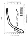
- FIG. 2 shows a plot of target temperature and apparent temperature together with pressure ramp rate each versus elapsed dispensing time.
- FIG. 3 shows a plot of target temperature, apparent temperature, and pressure ramp rate, each versus apparent pressure.
- FIG. 1 illustrates an example embodiment of a vessel filling system 100 according to the invention.
- the system 100 comprises a compressed gas supply 102 in the form of a supply vessel, a receiving vessel 108 , and a fluid conveyance 103 operatively connecting the receiving vessel 108 to the supply 102 .
- a heat exchanger 105 may be operatively disposed in the fluid conveyance 103 between the supply vessel 102 and the receiving vessel 108 .
- the receiving vessel 108 is equipped with pressure and temperature sensing equipment comprising a pressure sensor 110 and a temperature sensor 112 with associated transducers.
- the system 100 furthermore comprises a flow control device 104 disposed in the fluid conveyance 103 , and a flow controller 114 which communicates with the pressure sensor 110 and the temperature sensor 112 to receive pressure signals from the pressure sensor 110 and temperature signals from the temperature sensor 112 .
- the fluid conveyance 103 is comprised of a single conduit. It may however comprise one or more further conduits in parallel with each other, for example, similar to the fluid conveyance disclosed in US 2007/0079892 A1.
- the flow control device 104 is exemplified as a flow control valve, preferably a solenoid valve.
- the flow control device 104 can be any type of flow control device capable of varying a flow cross-sectional area of the fluid conveyance 103 incrementally or, preferably, continuously.
- the controller 114 communicates with the flow control device 104 to command the control device 104 in response to signals received from the pressure and temperature sensors 110 and 112 .
- the control device 104 and flow controller 114 are configured to control the flow rate of the compressed gas from the supply 102 to the receiving vessel 108 .
- the controller 114 can, in particular, be adapted to control the control device 104 and hence the gas flow rate such that the receiving vessel 108 is filled at a temperature adapted rate of pressure rise, a temperature adapted pressure ramp rate, i.e. an increase of gas pressure in the receiving vessel 108 per time unit measured in e.g. MPa/minute.
- the controller 114 can in particular be a PLC, capable of selecting the pressure ramp rate.
- the pressure ramp rate is selected to control the temperature of the receiving vessel 108 , determined by means of the temperature sensor 112 , to conform to a prescribed target temperature profile i.e. a temperature rise path.
- the control method can be any standard control method such as feed forward, feedback and/or PID control.
- an apparent temperature T 112 can be measured by means of the temperature sensor 112
- the flow rate of the compressed gas can be regulated by the controller 114 and control device 104 in a feedback control method, as desired.
- the temperature sensor 112 measures the temperature of the gas within the receiving vessel 108 .
- the gas temperature can be taken directly as the apparent temperature T 112 since it represents the temperature of critical vessel structures of the receiving vessel 108 in good approximation.
- the measured gas temperature can however instead be adjusted, e.g. according to a model of heat transfer between the gas and the surrounding vessel structure.
- the temperature sensor 112 may in modified variants directly measure the temperature of a heat critical structure of the receiving vessel 108 , and may in such variants for example be located at or in a shell structure of the vessel or measure heat radiated by the shell of the receiving vessel 108 .
- the temperature rise path i.e. the target temperature profile
- a target temperature profile provided as a temperature rise equation can be a function of the time elapsed since gas feed and filling have started and/or an apparent pressure P 110 representative for the instantaneous pressure in the receiving vessel 108 .
- the apparent pressure P 110 is determined by means of the pressure sensor 110 .
- the pressure sensor 110 may in particular be located such that it directly measures the pressure of the gas within the receiving vessel 108 .
- the above equation or another appropriate equation in which the target temperature profile, i.e. the target temperatures, are generated real-time during dispensing is implemented in the controller 114 , either as a hard-wired circuit or preferably as a programmed routine.
- the controller 114 receives the apparent pressure p 110 and the apparent temperature T 112 , it generates the target temperature T target in accordance with the implemented temperature rise equation and compares the instantaneous pair of temperatures, namely the target temperature T target and the apparent temperature T 112 , to determine a deviation ⁇ T of the apparent temperature T 110 from the target temperature T target .
- the prefix and/or the amount of the deviation e.g.
- the controller 114 creates an actuating variable AV to command the flow control device 104 such that the deviation ⁇ T is decreased.
- the controller 114 commands the control device 104 to decrease the flow rate of the compressed gas should the comparison reveal that the apparent temperature T 112 is too high and commands the control device 104 such that the flow rate is increased if the apparent temperature T 112 is too low.
- the controller 114 may command the control device 104 such that the apparent temperature T 112 is kept below the target temperature T target to the extent of a certain temperature safety margin.
- a control is also regarded as “conforming” the temperature profile.
- the apparent temperature is, for example, +51/ ⁇ 15° C. from the target temperature profile, the apparent temperature profile may be considered to conform to the target temperature profile.
- the apparent temperature profile may more closely conform to the target temperature profile, for example, +5/ ⁇ 10° C. or +1/ ⁇ 5° C. from the target temperature profile.
- the apparent temperature profile is produced from the apparent temperatures, that is it results from the apparent temperatures of the receiving vessel during dispensing.
- the apparent temperature profile may comprise the apparent temperatures during dispensing or a values calculated from the apparent temperatures.
- the apparent temperature may be stored in computer memory, but storing of the apparent temperature profile is not required.
- the rated maximum vessel temperature T max will typically be a preset temperature valid for all types of vessels which can be filled by the system 100 .
- the system 100 for example the flow controller 114 , may however also be capable of identifying the rated maximum vessel temperature of the receiving vessel 108 to be filled, respectively, and select T max accordingly.
- the coefficients X and Y are based exclusively on preset or preselectable values and process variables which are determined only once shortly before, at, or shortly after starting to feed the compressed gas and fill the receiving vessel 108 .
- These values and process variables are T max , the initial temperature T 0 of the receiving vessel 108 , the initial pressure P 0 in the receiving vessel 108 , the desired final target temperature and the desired pressure in the receiving vessel 108 at the end of filling.
- the initial temperature T 0 can in particular be the apparent temperature T 112 measured by means of the temperature sensor 110 shortly before, at, or shortly after starting the dispensing process.
- the initial pressure can be determined e.g.
- the desired final target temperature is a preselected upper temperature value of the temperature profile and is a temperature value below T max .
- the desired pressure in the receiving vessel 108 at the end of filling is a preselected upper pressure value of the receiving vessel 108 .
- the desired pressure at the end of fill can be a preset value of the flow controller 114 or be determined by the flow controller 114 based on identification data optionally received from the receiving vessel 108 , either automatically upon connection or inputted by an operator.
- the apparent pressure p 110 is the only variable of the temperature rise equation while filling proceeds.
- FIG. 2 is a plot derived from an example dispensing process according to the invention. It is a plot of target temperature T target in accordance with the above temperature rise equation, receiving vessel temperature T 112 , and the pressure ramp rate, i.e. the rate of pressure change within the receiving vessel 108 , measured in MPa per minute. On the x-axis the elapsed dispensing time is plotted in seconds of elapsed time.
- the receiving vessel 108 has been filled under field conditions up to a target temperature of 60° C.
- the sections of the graphs belonging to temperatures above 60° C. have been derived by extrapolation of the data gathered during the example dispensing process.
- a good match is achieved by rising the ramp rate in a first phase of the filling process up to a peak and decreasing it slowly from the peak in a consecutive second phase of the filling process to a value which can be kept relatively constant during the remainder of the filling process.
- the target temperature T target , the apparent temperature T 112 and the ramp rate are plotted versus the pressure within the receiving vessel 108 , for which in particular the apparent pressure p 110 can be taken.
- the graphs of FIG. 3 represent exclusively data from the example dispensing process performed under field conditions.
Landscapes
- Engineering & Computer Science (AREA)
- Mechanical Engineering (AREA)
- General Engineering & Computer Science (AREA)
- Filling Or Discharging Of Gas Storage Vessels (AREA)
Priority Applications (9)
| Application Number | Priority Date | Filing Date | Title |
|---|---|---|---|
| US13/867,208 US9279541B2 (en) | 2013-04-22 | 2013-04-22 | Method and system for temperature-controlled gas dispensing |
| ES14164054T ES2704875T5 (es) | 2013-04-22 | 2014-04-09 | Método y sistema para dispensación de gas a temperatura controlada |
| PT14164054T PT2796762T (pt) | 2013-04-22 | 2014-04-09 | Método e sistema para a distribuição de gás controlada por temperatura |
| EP14164054.0A EP2796762B2 (en) | 2013-04-22 | 2014-04-09 | Method and system for temperature-controlled gas dispensing |
| DK14164054.0T DK2796762T4 (da) | 2013-04-22 | 2014-04-09 | Fremgangsmåde og system til temperaturstyret dispensering af gas |
| JP2014087073A JP5947330B2 (ja) | 2013-04-22 | 2014-04-21 | 温度制御式の気体を分配する方法及びシステム |
| KR1020140047684A KR101596574B1 (ko) | 2013-04-22 | 2014-04-21 | 온도 제어식 가스 분배를 위한 방법 및 시스템 |
| CN201410161706.6A CN104110578B (zh) | 2013-04-22 | 2014-04-22 | 用于以温度受控制的方式进行气体分配的方法和系统 |
| CA2849542A CA2849542C (en) | 2013-04-22 | 2014-04-22 | Method and system for temperature-controlled gas dispensing |
Applications Claiming Priority (1)
| Application Number | Priority Date | Filing Date | Title |
|---|---|---|---|
| US13/867,208 US9279541B2 (en) | 2013-04-22 | 2013-04-22 | Method and system for temperature-controlled gas dispensing |
Publications (2)
| Publication Number | Publication Date |
|---|---|
| US20140311622A1 US20140311622A1 (en) | 2014-10-23 |
| US9279541B2 true US9279541B2 (en) | 2016-03-08 |
Family
ID=50442409
Family Applications (1)
| Application Number | Title | Priority Date | Filing Date |
|---|---|---|---|
| US13/867,208 Active 2034-05-13 US9279541B2 (en) | 2013-04-22 | 2013-04-22 | Method and system for temperature-controlled gas dispensing |
Country Status (9)
| Country | Link |
|---|---|
| US (1) | US9279541B2 (enExample) |
| EP (1) | EP2796762B2 (enExample) |
| JP (1) | JP5947330B2 (enExample) |
| KR (1) | KR101596574B1 (enExample) |
| CN (1) | CN104110578B (enExample) |
| CA (1) | CA2849542C (enExample) |
| DK (1) | DK2796762T4 (enExample) |
| ES (1) | ES2704875T5 (enExample) |
| PT (1) | PT2796762T (enExample) |
Cited By (26)
| Publication number | Priority date | Publication date | Assignee | Title |
|---|---|---|---|---|
| US9605804B2 (en) * | 2010-04-21 | 2017-03-28 | Honda Motor Co., Ltd. | Method and system for tank refilling using active fueling speed control |
| US20190120432A1 (en) * | 2017-03-31 | 2019-04-25 | Other Lab, Llc | Tank filling system and method |
| US10400712B2 (en) * | 2015-04-30 | 2019-09-03 | Westport Power Inc. | Intelligent pressure management system for cryogenic fluid systems |
| US10690288B2 (en) | 2015-06-15 | 2020-06-23 | Other Lab, Llc | System and method for a conformable pressure vessel |
| US10821657B2 (en) | 2015-12-02 | 2020-11-03 | Other Lab, Llc | Systems and methods for liner braiding and resin application |
| US10851925B2 (en) | 2016-10-24 | 2020-12-01 | Other Lab, Llc | Fittings for compressed gas storage vessels |
| US11136951B2 (en) * | 2017-11-22 | 2021-10-05 | Honda Motor Co., Ltd. | Gas fueling method |
| EP3889489A1 (en) * | 2020-04-01 | 2021-10-06 | Mirae EHS-code Research Institute | Hydrogen fueling system and method based on real-time communication information from chss for fuel cell |
| US11174032B2 (en) * | 2018-02-28 | 2021-11-16 | Airbus Operations Limited | Apparatus and method for heating an aircraft structure |
| US11306875B2 (en) * | 2018-12-06 | 2022-04-19 | Carrier Corporation | Systems and methods for controlling gas flow in transportation refrigeration systems |
| EP3855062A4 (en) * | 2018-09-21 | 2022-05-25 | National Institute of Clean-and-Low-Carbon Energy | DEVICE AND METHOD FOR CONTROLLING HYDROGEN REFUELING |
| EP4174362A1 (en) | 2021-10-29 | 2023-05-03 | Air Products and Chemicals, Inc. | Hydrogen storage and dispensing apparatus and method |
| EP4242457A1 (en) | 2022-03-08 | 2023-09-13 | Air Products and Chemicals, Inc. | Apparatus and method for cryogenic pump cooldown |
| US20240027028A1 (en) * | 2020-11-17 | 2024-01-25 | Mirae EHS-code Research Institute | Method For Performing Real-Time Response Hydrogen-Charging Process, And Device Therefor |
| US11946599B2 (en) | 2022-06-08 | 2024-04-02 | Air Products And Chemicals, Inc. | Apparatus and method for hydrogen fuel dispensing |
| EP4450863A1 (en) | 2023-04-20 | 2024-10-23 | Air Products and Chemicals, Inc. | Apparatus and method for dispensing a cryogenic fluid |
| US12129165B1 (en) * | 2023-04-26 | 2024-10-29 | Air Products And Chemicals, Inc. | Apparatus and method for fuel dispensing nozzle maintenance or vehicle battery recharging nozzle maintenance |
| US12222073B1 (en) * | 2024-04-19 | 2025-02-11 | ZeroAvia, Inc. | Interrogation of temperature sensitive coatings on fuel tank exterior |
| EP4517154A1 (en) | 2023-08-30 | 2025-03-05 | Air Products and Chemicals, Inc. | Apparatus and process for cryogenic liquid vaporization to recool gas for cryogenic fluid recovery |
| EP4534182A1 (en) | 2023-08-30 | 2025-04-09 | Air Products and Chemicals, Inc. | Apparatus and process for fog mitigation |
| EP4546237A1 (en) | 2023-10-24 | 2025-04-30 | Air Products and Chemicals, Inc. | Apparatus and process for controlling a display for fuel dispensing |
| EP4556780A1 (en) | 2023-11-20 | 2025-05-21 | Air Products and Chemicals, Inc. | Apparatus and process for cooling pressurized gas for fueling |
| WO2025158144A1 (en) * | 2024-01-22 | 2025-07-31 | Hykit Limited | A portable refuelling device |
| WO2025226381A1 (en) | 2024-04-24 | 2025-10-30 | Air Products And Chemicals, Inc. | Apparatus, control system and process for rapid fuel dispensing |
| WO2025226380A1 (en) | 2024-04-24 | 2025-10-30 | Air Products And Chemicals, Inc. | Apparatus, control system and process for rapid fuel dispensing |
| US12497936B2 (en) | 2023-11-20 | 2025-12-16 | Air Products And Chemicals, Inc. | Apparatus and process for cooling pressurized gas for fueling |
Families Citing this family (25)
| Publication number | Priority date | Publication date | Assignee | Title |
|---|---|---|---|---|
| JP5591854B2 (ja) * | 2012-03-19 | 2014-09-17 | 本田技研工業株式会社 | 移動体及びその燃料充填システム |
| US10088109B2 (en) * | 2014-11-03 | 2018-10-02 | Gilbarco Inc. | Compressed gas filling method and system |
| RU2676509C1 (ru) * | 2015-01-30 | 2018-12-29 | Дэу Шипбилдинг Энд Марин Инджиниринг Ко., Лтд. | Система и способ подачи топлива к судовому двигателю |
| US10409657B2 (en) * | 2016-01-15 | 2019-09-10 | Google Llc | Identifiers across application instances |
| DE102016208166A1 (de) * | 2016-05-12 | 2017-11-16 | Robert Bosch Gmbh | Kraftstoffversorgungssystem für eine gasbetriebene Brennkraftmaschine und Verfahren zum Betreiben eines Kraftstoffversorgungssystems |
| EP3249281B1 (en) * | 2016-05-23 | 2022-02-23 | Air Products And Chemicals, Inc. | Compressed gas dispensing |
| ES2837249T3 (es) * | 2016-05-23 | 2021-06-29 | Air Prod & Chem | Distribución de gas comprimido |
| FR3057644B1 (fr) * | 2016-10-19 | 2018-10-19 | L'air Liquide, Societe Anonyme Pour L'etude Et L'exploitation Des Procedes Georges Claude | Procede et dispositif de remplissage d'un reservoir de gaz sous pression |
| US9897260B1 (en) * | 2017-04-18 | 2018-02-20 | Air Products And Chemicals, Inc. | Control system in an industrial gas pipeline network to satisfy energy consumption constraints at production plants |
| JP7048417B2 (ja) * | 2018-05-29 | 2022-04-05 | Eneos株式会社 | 水素ガス充填方法及び水素ガス充填装置 |
| CN109000147A (zh) * | 2018-07-20 | 2018-12-14 | 上海汽车集团股份有限公司 | 移动式氢供给系统、方法、装置、计算机可读存储介质 |
| US11499765B2 (en) | 2018-08-01 | 2022-11-15 | L'air Liquide, Societe Anonyme Pour L'etude Et L'exploitation Des Procedes Georges Claude | Device and process for refueling containers with pressurized gas |
| US11506339B2 (en) | 2018-08-01 | 2022-11-22 | L'air Liquide, Societe Anonyme Pour L'etude Et L'exploitation Des Procedes Georges Claude | Device and process for refueling containers with pressurized gas |
| US11287087B2 (en) * | 2018-08-01 | 2022-03-29 | L'air Liquide Societe Anonyme Pour L'etude Et L'exploitation Des Procedes Georges Claude | Device and process for refueling containers with pressurized gas |
| RU2703899C1 (ru) * | 2018-08-13 | 2019-10-22 | Акционерное общество "Государственный космический научно-производственный центр им. М.В. Хруничева" | Способ наполнения емкостей сжатым газом до требуемого давления и устройство для его реализации |
| CN110939858B (zh) * | 2018-09-21 | 2022-04-12 | 国家能源投资集团有限责任公司 | 加氢站控制方法、装置以及加氢站 |
| CN109654372A (zh) * | 2018-12-05 | 2019-04-19 | 潍柴动力股份有限公司 | 一种储氢设备的控制方法及装置 |
| FR3098274B1 (fr) * | 2019-07-03 | 2022-01-28 | Air Liquide | Dispositif et procédé de remplissage de réservoirs. |
| RU2739662C1 (ru) * | 2020-01-20 | 2020-12-28 | Публичное акционерное общество "Ракетно-космическая корпорация "Энергия" имени С.П. Королева" | Способ заправки сжатым газом изделий |
| US12066152B2 (en) * | 2020-10-27 | 2024-08-20 | H2 Clipper, Inc. | Method and apparatus for delivering hydrogen |
| WO2023055976A1 (en) * | 2021-10-01 | 2023-04-06 | FirstElement Fuel, Inc. | Gaseous hydrogen fueling methods |
| JP7582926B2 (ja) * | 2021-10-18 | 2024-11-13 | 本田技研工業株式会社 | 水素充填装置の制御方法、及び、水素充填装置 |
| US20230381562A1 (en) * | 2022-05-25 | 2023-11-30 | Carrier Corporation | In-situ pressurized restaurant system |
| CN115234830B (zh) * | 2022-06-29 | 2024-02-20 | 潍柴动力股份有限公司 | 一种加氢方法及加氢站 |
| DE102023200438A1 (de) * | 2023-01-20 | 2024-07-25 | Robert Bosch Gesellschaft mit beschränkter Haftung | Verfahren zum Betreiben einer Tankvorrichtung zum Speichern eines Gastreibstoffs und Tankvorrichtung zum Speichern eines Gastreibstoffs |
Citations (25)
| Publication number | Priority date | Publication date | Assignee | Title |
|---|---|---|---|---|
| JPH08100895A (ja) | 1994-09-30 | 1996-04-16 | Tokyo Gas Co Ltd | ガス供給装置 |
| WO1996022915A1 (en) | 1995-01-25 | 1996-08-01 | Pinnacle Cng Systems, L.L.C. | System and method for dispensing pressurized gas |
| JPH09183988A (ja) | 1995-12-28 | 1997-07-15 | Tokyo Gas Co Ltd | 気化器パネルの異常監視における温度の変曲点の抽出方法 |
| US5868176A (en) | 1997-05-27 | 1999-02-09 | Gas Research Institute | System for controlling the fill of compressed natural gas cylinders |
| US5901758A (en) * | 1997-04-30 | 1999-05-11 | The Boc Group, Inc. | Method of filling gas containers |
| EP1336795A2 (en) | 2002-02-14 | 2003-08-20 | Air Products And Chemicals, Inc. | System and method for dispensing pressurized gas |
| US6708573B1 (en) * | 2002-09-12 | 2004-03-23 | Air Products And Chemicals, Inc. | Process for filling compressed gas fuel dispensers which utilizes volume and density calculations |
| US20060180237A1 (en) | 2005-02-17 | 2006-08-17 | Hoke Bryan C Jr | System and method for dispensing compressed gas |
| US7178565B2 (en) | 2003-02-21 | 2007-02-20 | Air Products And Chemicals, Inc. | Self-contained mobile fueling station |
| US20070079892A1 (en) | 2005-10-10 | 2007-04-12 | Cohen Joseph P | Gas filling system |
| EP1818597A2 (en) | 2006-02-10 | 2007-08-15 | Air Products and Chemicals, Inc. | Method for dispensing compressed gas |
| EP1865248A1 (en) | 2006-06-07 | 2007-12-12 | Air Products and Chemicals, Inc. | Hydrogen dispenser with user-selectable hydrogen dispensing rate algorithms |
| US7328726B2 (en) * | 2006-01-20 | 2008-02-12 | Air Products And Chemicals, Inc. | Ramp rate blender |
| JP2008538321A (ja) | 2005-04-22 | 2008-10-23 | オングストローム パワー インク. | 水素貯蔵複合材料およびそれに関する方法 |
| US7568507B2 (en) * | 2005-12-06 | 2009-08-04 | Air Products And Chemicals, Inc. | Diagnostic method and apparatus for a pressurized gas supply system |
| US7575012B2 (en) * | 2003-07-25 | 2009-08-18 | Toyota Jidosha Kabushiki Kaisha | Gas supply apparatus |
| EP2093475A1 (en) | 2008-02-20 | 2009-08-26 | Air Products and Chemicals, Inc. | Compressor fill method and apparatus |
| JP2010236673A (ja) | 2009-03-31 | 2010-10-21 | Denso Corp | 流動体充填システム、移動体、及び供給設備 |
| US20100307636A1 (en) | 2009-06-09 | 2010-12-09 | Honda Motor Co., Ltd. | Hydrogen filling apparatus and hydrogen filling method |
| US7905252B2 (en) * | 2006-03-20 | 2011-03-15 | Tescom Corporation | Apparatus and methods to dispense fluid from a bank of containers and to refill same |
| US8020589B2 (en) * | 2007-01-04 | 2011-09-20 | Air Products And Chemicals, Inc. | Hydrogen dispensing station and method of operating the same |
| DE102010027683A1 (de) | 2010-07-20 | 2012-01-26 | Linde Aktiengesellschaft | Tankstelle mit Kommunikation |
| US20120031525A1 (en) * | 2010-08-04 | 2012-02-09 | Scott Fredric Wonders | Compressed gas flow initiated and controlled automatic sequencing cascade system for the recharging of compressed gas cylinders |
| US20120216910A1 (en) | 2009-11-16 | 2012-08-30 | Shusuke Inagi | Gas charging apparatus and gas charging method |
| US20130014854A1 (en) | 2010-01-25 | 2013-01-17 | Tomoyuki Mori | Fuel gas station, fuel gas filling system, and fuel gas supplying method |
Family Cites Families (8)
| Publication number | Priority date | Publication date | Assignee | Title |
|---|---|---|---|---|
| US6152192A (en) | 1998-02-11 | 2000-11-28 | Welding Company Of America | Controller for system for filling gas cylinders with single gas or gas mixture |
| JP2002115796A (ja) | 2000-10-05 | 2002-04-19 | Nippon Sanso Corp | 高圧ガスの充填方法 |
| FI111174B (fi) * | 2000-10-27 | 2003-06-13 | Metso Paper Inc | Menetelmä ja laite rainan päänviennissä paperikoneen tai vastaavan kuivatusosassa |
| JP2004144128A (ja) | 2002-10-22 | 2004-05-20 | Nissan Motor Co Ltd | 燃料ガス充填装置 |
| JP4913427B2 (ja) * | 2006-03-10 | 2012-04-11 | 大陽日酸株式会社 | 水素ガスの充填方法及び装置 |
| FR2920858B1 (fr) | 2007-09-10 | 2009-11-27 | Air Liquide | Procede de remplissage de conteneur de gaz sous pression |
| CN101315545B (zh) * | 2008-06-27 | 2010-06-09 | 浙江大学 | 一种加氢站高效加氢的三级氢气加注系统 |
| DE112009004397B8 (de) * | 2009-01-19 | 2017-11-30 | Toyota Jidosha Kabushiki Kaisha | Hochdruck-Fluidversorgungsvorrichtung |
-
2013
- 2013-04-22 US US13/867,208 patent/US9279541B2/en active Active
-
2014
- 2014-04-09 ES ES14164054T patent/ES2704875T5/es active Active
- 2014-04-09 DK DK14164054.0T patent/DK2796762T4/da active
- 2014-04-09 EP EP14164054.0A patent/EP2796762B2/en active Active
- 2014-04-09 PT PT14164054T patent/PT2796762T/pt unknown
- 2014-04-21 JP JP2014087073A patent/JP5947330B2/ja active Active
- 2014-04-21 KR KR1020140047684A patent/KR101596574B1/ko active Active
- 2014-04-22 CN CN201410161706.6A patent/CN104110578B/zh active Active
- 2014-04-22 CA CA2849542A patent/CA2849542C/en active Active
Patent Citations (29)
| Publication number | Priority date | Publication date | Assignee | Title |
|---|---|---|---|---|
| JPH08100895A (ja) | 1994-09-30 | 1996-04-16 | Tokyo Gas Co Ltd | ガス供給装置 |
| WO1996022915A1 (en) | 1995-01-25 | 1996-08-01 | Pinnacle Cng Systems, L.L.C. | System and method for dispensing pressurized gas |
| JPH09183988A (ja) | 1995-12-28 | 1997-07-15 | Tokyo Gas Co Ltd | 気化器パネルの異常監視における温度の変曲点の抽出方法 |
| US5901758A (en) * | 1997-04-30 | 1999-05-11 | The Boc Group, Inc. | Method of filling gas containers |
| US5868176A (en) | 1997-05-27 | 1999-02-09 | Gas Research Institute | System for controlling the fill of compressed natural gas cylinders |
| US6619336B2 (en) | 2002-02-14 | 2003-09-16 | Air Products And Chemicals, Inc. | System and method for dispensing pressurized gas |
| EP1336795A2 (en) | 2002-02-14 | 2003-08-20 | Air Products And Chemicals, Inc. | System and method for dispensing pressurized gas |
| US6708573B1 (en) * | 2002-09-12 | 2004-03-23 | Air Products And Chemicals, Inc. | Process for filling compressed gas fuel dispensers which utilizes volume and density calculations |
| US7178565B2 (en) | 2003-02-21 | 2007-02-20 | Air Products And Chemicals, Inc. | Self-contained mobile fueling station |
| US7575012B2 (en) * | 2003-07-25 | 2009-08-18 | Toyota Jidosha Kabushiki Kaisha | Gas supply apparatus |
| US20060180237A1 (en) | 2005-02-17 | 2006-08-17 | Hoke Bryan C Jr | System and method for dispensing compressed gas |
| EP1693612A2 (en) | 2005-02-17 | 2006-08-23 | Air Products and Chemicals, Inc. | System and method for dispensing compressed gas |
| JP2008538321A (ja) | 2005-04-22 | 2008-10-23 | オングストローム パワー インク. | 水素貯蔵複合材料およびそれに関する方法 |
| US20070079892A1 (en) | 2005-10-10 | 2007-04-12 | Cohen Joseph P | Gas filling system |
| US7568507B2 (en) * | 2005-12-06 | 2009-08-04 | Air Products And Chemicals, Inc. | Diagnostic method and apparatus for a pressurized gas supply system |
| US7328726B2 (en) * | 2006-01-20 | 2008-02-12 | Air Products And Chemicals, Inc. | Ramp rate blender |
| EP1818597A2 (en) | 2006-02-10 | 2007-08-15 | Air Products and Chemicals, Inc. | Method for dispensing compressed gas |
| US7905252B2 (en) * | 2006-03-20 | 2011-03-15 | Tescom Corporation | Apparatus and methods to dispense fluid from a bank of containers and to refill same |
| EP1865248A1 (en) | 2006-06-07 | 2007-12-12 | Air Products and Chemicals, Inc. | Hydrogen dispenser with user-selectable hydrogen dispensing rate algorithms |
| US8020589B2 (en) * | 2007-01-04 | 2011-09-20 | Air Products And Chemicals, Inc. | Hydrogen dispensing station and method of operating the same |
| EP2093475A1 (en) | 2008-02-20 | 2009-08-26 | Air Products and Chemicals, Inc. | Compressor fill method and apparatus |
| US8365777B2 (en) | 2008-02-20 | 2013-02-05 | Air Products And Chemicals, Inc. | Compressor fill method and apparatus |
| JP2010236673A (ja) | 2009-03-31 | 2010-10-21 | Denso Corp | 流動体充填システム、移動体、及び供給設備 |
| US8684044B2 (en) | 2009-03-31 | 2014-04-01 | Denso Corporation | Fluid charging system, movable object, supply facility, and method for controlling fluid charge |
| US20100307636A1 (en) | 2009-06-09 | 2010-12-09 | Honda Motor Co., Ltd. | Hydrogen filling apparatus and hydrogen filling method |
| US20120216910A1 (en) | 2009-11-16 | 2012-08-30 | Shusuke Inagi | Gas charging apparatus and gas charging method |
| US20130014854A1 (en) | 2010-01-25 | 2013-01-17 | Tomoyuki Mori | Fuel gas station, fuel gas filling system, and fuel gas supplying method |
| DE102010027683A1 (de) | 2010-07-20 | 2012-01-26 | Linde Aktiengesellschaft | Tankstelle mit Kommunikation |
| US20120031525A1 (en) * | 2010-08-04 | 2012-02-09 | Scott Fredric Wonders | Compressed gas flow initiated and controlled automatic sequencing cascade system for the recharging of compressed gas cylinders |
Cited By (33)
| Publication number | Priority date | Publication date | Assignee | Title |
|---|---|---|---|---|
| US9605804B2 (en) * | 2010-04-21 | 2017-03-28 | Honda Motor Co., Ltd. | Method and system for tank refilling using active fueling speed control |
| US10400712B2 (en) * | 2015-04-30 | 2019-09-03 | Westport Power Inc. | Intelligent pressure management system for cryogenic fluid systems |
| US10982626B2 (en) * | 2015-04-30 | 2021-04-20 | Westport Power Inc. | Intelligent pressure management system for cryogenic fluid systems |
| US10690288B2 (en) | 2015-06-15 | 2020-06-23 | Other Lab, Llc | System and method for a conformable pressure vessel |
| US10821657B2 (en) | 2015-12-02 | 2020-11-03 | Other Lab, Llc | Systems and methods for liner braiding and resin application |
| US11000988B2 (en) | 2015-12-02 | 2021-05-11 | Other Lab, Llc | Systems and methods for liner braiding and resin application |
| US10851925B2 (en) | 2016-10-24 | 2020-12-01 | Other Lab, Llc | Fittings for compressed gas storage vessels |
| US20190120432A1 (en) * | 2017-03-31 | 2019-04-25 | Other Lab, Llc | Tank filling system and method |
| US10845005B2 (en) * | 2017-03-31 | 2020-11-24 | Other Lab, Llc | Tank filling system and method |
| US11136951B2 (en) * | 2017-11-22 | 2021-10-05 | Honda Motor Co., Ltd. | Gas fueling method |
| US11667388B2 (en) | 2018-02-28 | 2023-06-06 | Airbus Operations Limited | Apparatus and method for heating an aircraft structure |
| US11174032B2 (en) * | 2018-02-28 | 2021-11-16 | Airbus Operations Limited | Apparatus and method for heating an aircraft structure |
| US12085233B2 (en) | 2018-09-21 | 2024-09-10 | National Institute Of Clean-And-Low-Carbon Energy | Hydrogen fueling control device and method |
| EP3855062A4 (en) * | 2018-09-21 | 2022-05-25 | National Institute of Clean-and-Low-Carbon Energy | DEVICE AND METHOD FOR CONTROLLING HYDROGEN REFUELING |
| US11306875B2 (en) * | 2018-12-06 | 2022-04-19 | Carrier Corporation | Systems and methods for controlling gas flow in transportation refrigeration systems |
| US11293595B2 (en) | 2020-04-01 | 2022-04-05 | Mirae EHS-code Research Institute | Hydrogen fueling system and method based on real-time communication information from CHSS for fuel cell |
| EP3889489A1 (en) * | 2020-04-01 | 2021-10-06 | Mirae EHS-code Research Institute | Hydrogen fueling system and method based on real-time communication information from chss for fuel cell |
| US20240027028A1 (en) * | 2020-11-17 | 2024-01-25 | Mirae EHS-code Research Institute | Method For Performing Real-Time Response Hydrogen-Charging Process, And Device Therefor |
| EP4174362A1 (en) | 2021-10-29 | 2023-05-03 | Air Products and Chemicals, Inc. | Hydrogen storage and dispensing apparatus and method |
| US12092093B2 (en) | 2022-03-08 | 2024-09-17 | Air Products And Chemicals, Inc. | Apparatus and method for cryogenic pump cooldown |
| EP4242457A1 (en) | 2022-03-08 | 2023-09-13 | Air Products and Chemicals, Inc. | Apparatus and method for cryogenic pump cooldown |
| US11946599B2 (en) | 2022-06-08 | 2024-04-02 | Air Products And Chemicals, Inc. | Apparatus and method for hydrogen fuel dispensing |
| EP4450863A1 (en) | 2023-04-20 | 2024-10-23 | Air Products and Chemicals, Inc. | Apparatus and method for dispensing a cryogenic fluid |
| US12129165B1 (en) * | 2023-04-26 | 2024-10-29 | Air Products And Chemicals, Inc. | Apparatus and method for fuel dispensing nozzle maintenance or vehicle battery recharging nozzle maintenance |
| EP4534182A1 (en) | 2023-08-30 | 2025-04-09 | Air Products and Chemicals, Inc. | Apparatus and process for fog mitigation |
| EP4517154A1 (en) | 2023-08-30 | 2025-03-05 | Air Products and Chemicals, Inc. | Apparatus and process for cryogenic liquid vaporization to recool gas for cryogenic fluid recovery |
| EP4546237A1 (en) | 2023-10-24 | 2025-04-30 | Air Products and Chemicals, Inc. | Apparatus and process for controlling a display for fuel dispensing |
| EP4556780A1 (en) | 2023-11-20 | 2025-05-21 | Air Products and Chemicals, Inc. | Apparatus and process for cooling pressurized gas for fueling |
| US12497936B2 (en) | 2023-11-20 | 2025-12-16 | Air Products And Chemicals, Inc. | Apparatus and process for cooling pressurized gas for fueling |
| WO2025158144A1 (en) * | 2024-01-22 | 2025-07-31 | Hykit Limited | A portable refuelling device |
| US12222073B1 (en) * | 2024-04-19 | 2025-02-11 | ZeroAvia, Inc. | Interrogation of temperature sensitive coatings on fuel tank exterior |
| WO2025226381A1 (en) | 2024-04-24 | 2025-10-30 | Air Products And Chemicals, Inc. | Apparatus, control system and process for rapid fuel dispensing |
| WO2025226380A1 (en) | 2024-04-24 | 2025-10-30 | Air Products And Chemicals, Inc. | Apparatus, control system and process for rapid fuel dispensing |
Also Published As
| Publication number | Publication date |
|---|---|
| JP2014214874A (ja) | 2014-11-17 |
| ES2704875T3 (es) | 2019-03-20 |
| EP2796762A1 (en) | 2014-10-29 |
| KR20140126262A (ko) | 2014-10-30 |
| DK2796762T3 (en) | 2019-04-08 |
| PT2796762T (pt) | 2019-03-20 |
| CA2849542C (en) | 2015-12-01 |
| CN104110578B (zh) | 2017-04-12 |
| EP2796762B2 (en) | 2022-01-19 |
| CA2849542A1 (en) | 2014-10-22 |
| CN104110578A (zh) | 2014-10-22 |
| ES2704875T5 (es) | 2022-04-19 |
| DK2796762T4 (da) | 2022-02-21 |
| US20140311622A1 (en) | 2014-10-23 |
| JP5947330B2 (ja) | 2016-07-06 |
| EP2796762B1 (en) | 2018-12-19 |
| KR101596574B1 (ko) | 2016-02-22 |
Similar Documents
| Publication | Publication Date | Title |
|---|---|---|
| US9279541B2 (en) | Method and system for temperature-controlled gas dispensing | |
| US10995913B2 (en) | Vehicle and method for filling fuel gas | |
| US10443784B2 (en) | System for controlling gas supply unit | |
| US8360112B2 (en) | Method and device for filling pressure gas containers | |
| US8365777B2 (en) | Compressor fill method and apparatus | |
| JP4071648B2 (ja) | 昇圧ガス分配装置及び方法 | |
| JP3507148B2 (ja) | 圧力容器にガス媒体を迅速に充填する方法及び装置 | |
| US20070186982A1 (en) | Method for dispensing compressed gas | |
| JP2014214874A5 (enExample) | ||
| EP1772663B1 (en) | Gas filling system | |
| US8517062B2 (en) | Method for filling a pressurized gas container | |
| CN102859255A (zh) | 气体填充方法、气体填充系统、气站和移动单元 | |
| JP2017053459A (ja) | ガス充填方法 | |
| KR20220085830A (ko) | 누출 감지 | |
| JP6179273B2 (ja) | 燃料ガス充填装置 | |
| JP2006112901A (ja) | 可変型脈動圧配管試験システム | |
| JP3580353B2 (ja) | 圧力発生器 | |
| JP2015113938A (ja) | 圧力発生充填装置 |
Legal Events
| Date | Code | Title | Description |
|---|---|---|---|
| AS | Assignment |
Owner name: AIR PRODUCTS AND CHEMICALS, INC., PENNSYLVANIA Free format text: ASSIGNMENT OF ASSIGNORS INTEREST;ASSIGNOR:COHEN, JOSEPH PERRY;REEL/FRAME:030387/0499 Effective date: 20130422 |
|
| STCF | Information on status: patent grant |
Free format text: PATENTED CASE |
|
| MAFP | Maintenance fee payment |
Free format text: PAYMENT OF MAINTENANCE FEE, 4TH YEAR, LARGE ENTITY (ORIGINAL EVENT CODE: M1551); ENTITY STATUS OF PATENT OWNER: LARGE ENTITY Year of fee payment: 4 |
|
| MAFP | Maintenance fee payment |
Free format text: PAYMENT OF MAINTENANCE FEE, 8TH YEAR, LARGE ENTITY (ORIGINAL EVENT CODE: M1552); ENTITY STATUS OF PATENT OWNER: LARGE ENTITY Year of fee payment: 8 |