US9254397B2 - Plasma evaluation apparatus - Google Patents
Plasma evaluation apparatus Download PDFInfo
- Publication number
- US9254397B2 US9254397B2 US14/359,970 US201214359970A US9254397B2 US 9254397 B2 US9254397 B2 US 9254397B2 US 201214359970 A US201214359970 A US 201214359970A US 9254397 B2 US9254397 B2 US 9254397B2
- Authority
- US
- United States
- Prior art keywords
- plasma
- current
- measure
- voltage
- evaluation system
- Prior art date
- Legal status (The legal status is an assumption and is not a legal conclusion. Google has not performed a legal analysis and makes no representation as to the accuracy of the status listed.)
- Active
Links
Images


Classifications
-
- A—HUMAN NECESSITIES
- A61—MEDICAL OR VETERINARY SCIENCE; HYGIENE
- A61N—ELECTROTHERAPY; MAGNETOTHERAPY; RADIATION THERAPY; ULTRASOUND THERAPY
- A61N5/00—Radiation therapy
- A61N5/10—X-ray therapy; Gamma-ray therapy; Particle-irradiation therapy
- A61N5/1048—Monitoring, verifying, controlling systems and methods
- A61N5/1064—Monitoring, verifying, controlling systems and methods for adjusting radiation treatment in response to monitoring
-
- A—HUMAN NECESSITIES
- A61—MEDICAL OR VETERINARY SCIENCE; HYGIENE
- A61B—DIAGNOSIS; SURGERY; IDENTIFICATION
- A61B18/00—Surgical instruments, devices or methods for transferring non-mechanical forms of energy to or from the body
- A61B18/04—Surgical instruments, devices or methods for transferring non-mechanical forms of energy to or from the body by heating
- A61B18/042—Surgical instruments, devices or methods for transferring non-mechanical forms of energy to or from the body by heating using additional gas becoming plasma
-
- H—ELECTRICITY
- H05—ELECTRIC TECHNIQUES NOT OTHERWISE PROVIDED FOR
- H05H—PLASMA TECHNIQUE; PRODUCTION OF ACCELERATED ELECTRICALLY-CHARGED PARTICLES OR OF NEUTRONS; PRODUCTION OR ACCELERATION OF NEUTRAL MOLECULAR OR ATOMIC BEAMS
- H05H1/00—Generating plasma; Handling plasma
- H05H1/0006—Investigating plasma, e.g. measuring the degree of ionisation or the electron temperature
- H05H1/0081—Investigating plasma, e.g. measuring the degree of ionisation or the electron temperature by electric means
-
- A—HUMAN NECESSITIES
- A61—MEDICAL OR VETERINARY SCIENCE; HYGIENE
- A61B—DIAGNOSIS; SURGERY; IDENTIFICATION
- A61B17/00—Surgical instruments, devices or methods
- A61B2017/00017—Electrical control of surgical instruments
- A61B2017/00022—Sensing or detecting at the treatment site
- A61B2017/00057—Light
-
- A—HUMAN NECESSITIES
- A61—MEDICAL OR VETERINARY SCIENCE; HYGIENE
- A61B—DIAGNOSIS; SURGERY; IDENTIFICATION
- A61B18/00—Surgical instruments, devices or methods for transferring non-mechanical forms of energy to or from the body
- A61B2018/00636—Sensing and controlling the application of energy
- A61B2018/00642—Sensing and controlling the application of energy with feedback, i.e. closed loop control
-
- A—HUMAN NECESSITIES
- A61—MEDICAL OR VETERINARY SCIENCE; HYGIENE
- A61B—DIAGNOSIS; SURGERY; IDENTIFICATION
- A61B18/00—Surgical instruments, devices or methods for transferring non-mechanical forms of energy to or from the body
- A61B2018/00636—Sensing and controlling the application of energy
- A61B2018/00773—Sensed parameters
- A61B2018/00827—Current
-
- A—HUMAN NECESSITIES
- A61—MEDICAL OR VETERINARY SCIENCE; HYGIENE
- A61B—DIAGNOSIS; SURGERY; IDENTIFICATION
- A61B18/00—Surgical instruments, devices or methods for transferring non-mechanical forms of energy to or from the body
- A61B2018/00636—Sensing and controlling the application of energy
- A61B2018/00773—Sensed parameters
- A61B2018/00892—Voltage
Definitions
- the present invention relates to a plasma evaluation system.
- the current flowing between the voltage application electrode and a ground electrode of the plasma equipment is joined by a current flowing through a living body.
- the current flowing through the living body has a pulsed shape fluctuating temporally sharply, and there is also a displacement current component to join them, which makes it likely for the voltage applied to the electrode to fluctuate according to the plasma state, which consequently results in fluctuation of the plasma state.
- the plasma state, the voltage across the electrodes of the plasma generation equipment, the current between the electrodes of the plasma generation equipment, and the current flowing through the living body are related with each other. Even though it has been possible to measure the current of the supply-side power source of the plasma generation equipment, it has not been easy to separate the current flowing through the living body therefrom, because the current is superposed with the current between the electrodes of the plasma generation equipment.
- the problems are the inability to easily measure and evaluate plasma characteristics of medical plasma treatment equipments expected to spread at home and abroad, and unavailability, particularly at the medical front, of a user-friendly system taking into consideration operability, hygiene, and compactness. That is, there has not been an evaluation system that can maintain and manage the initial performance of the plasma equipments for safety and security, and in addition, it has not been possible to perform a plasma treatment while easily monitoring (measuring or evaluating) the plasma state.
- PTL 2 describes a plasma treatment equipment that, with a photon detecting sensor for measurement of an ultraviolet-induced current provided on a wafer stage, detects an abnormal electrical discharge phenomenon to occur in the plasma chamber real-time simultaneously with an ongoing semiconductor wafer treatment.
- this equipment is an industrial plasma treatment equipment for wafer fabrication, etc. configured to measure a photoelectron current attributable to an abnormal electrical discharge to occur in a region different from a region for a main electrical discharge, and not configured to measure a current to flow through a treatment target of medical plasma treatment equipments, particularly, a living body, etc. Therefore, this equipment can neither be applied to medical purposes, nor used conveniently at the medical front.
- a plasma evaluation system of the present invention includes:
- a weak current measurement unit including a resistor unit and a differential amplifier
- the treatment target material is connected to the weak current measurement unit via a treatment target side measurement terminal
- resistor unit of the weak current measurement unit is connected to a ground side of a plasma generation power source
- the plasma evaluation system is configured to evaluate plasma by receiving plasma generated by a plasma treatment equipment with the treatment target material, measuring a current of a voltage across resistors of the resistor unit through the differential amplifier, and measuring an output voltage of the plasma generation power source.
- the resistors of the resistor unit are variable, or resistance values are switchable.
- the plasma evaluation system of the present invention is configured to measure an output signal of the differential amplifier and a signal of a voltage by transmitting the signals through an analog optical converter and an optical fiber, converting the signals to electric signals at a light receiving unit, and inputting the electric signals to an analog-digital converter.
- the plasma evaluation system of the present invention is configured to measure the output signal of the differential amplifier and the signal of the voltage by inputting the signals to the analog-digital converter, further converting the signals to light to thereby transmit the signals through an optical fiber as electrically insulated data, and inputting the signals to another analog-digital converter.
- the plasma evaluation system of the present invention is configured to measure a current of the plasma treatment equipment when the treatment target material is a terminal for performance evaluation, measure a current of a small-sized animal such as a mouse when the treatment target material is a tray, with the small-sized animal on the tray, measure a current flowing through a human being or a middle-sized animal when the treatment target material is an examination table, or measure a current flowing through a part of a human body when the treatment target material is an electrode pad.
- the plasma evaluation system of the present invention is configured to:
- (A-1) apply a voltage to the plasma treatment equipment under conditions for not generating plasma, and measure a resulting voltage value V1 and a resulting current value I1;
- (A-2) apply a voltage to the plasma treatment equipment under conditions for generating plasma to generate plasma;
- (A-3) adjust an output from the supply power source such that a voltage value equal to the voltage value V1 of (A-1) is obtained, and measure a resulting current value I3;
- (A-4) adjust the phases of the currents measured in (A-1) and (A-3) to align the peaks of the currents, subtract the current value I1 of (A-1) from the current value I3 of (A-3), and evaluate a resulting value, i.e., I3 ⁇ I1, as a current component that has actually flowed,
- (B-1) apply a voltage to the plasma treatment equipment under conditions for not generating plasma, and measure a resulting voltage value V1 and a resulting current value I1;
- (B-2) apply a voltage to the plasma treatment equipment under conditions for generating plasma to generate plasma, and measure a resulting voltage value V2 and a resulting current value I2;
- (B-3) adjust the phase of the current measured in (B-1) to align the peak of the current with (V1/V2) ⁇ I2, which is obtained by multiplying a ratio between the voltage values of (B-1) and (B-2) by the current of (B-2), subtract I1 from (V1/V2) ⁇ I2, and evaluate a resulting value, i.e., (V1/V2) ⁇ I2 ⁇ I1, in other words, V1 ⁇ I2/V2 ⁇ I1, as a current component that has actually flowed.
- the plasma evaluation system of the present invention is configured to measure a current through a Rogowski coil or a current transformer attached between an output of the resistor unit and the ground side of the plasma generation power source.
- the plasma evaluation system of the present invention includes:
- a treatment target material connected to a ground side of a plasma generation power source via a treatment target side measurement terminal;
- a Rogowski coil or a current transformer attached between the treatment target side measurement terminal and the ground side of the plasma generation power source
- the plasma evaluation system is configured to evaluate plasma by receiving plasma generated by a plasma treatment equipment with the treatment target material, measuring a current through the Rogowski coil or the current transformer, and measuring an output voltage of the plasma generation power source, and
- the plasma evaluation system is configured to measure a current of the plasma treatment equipment when the treatment target material is a terminal for performance evaluation, measure a current of a small-sized animal such as a mouse when the treatment target material is a tray, with the small-sized animal on the tray, measure a current flowing through a human being or a middle-sized animal when the treatment target material is an examination table, or measure a current flowing through a part of a human body when the treatment target material is an electrode pad.
- the plasma evaluation system of the present invention is configured to measure an output signal of an amplifier of the Rogowski coil or the current transformer by inputting the output signal to an analog-digital converter, or to measure the output signal of the amplifier by transmitting the output signal through an analog optical converter and an optical fiber, converting the output signal to an electric signal at a light receiving unit, and inputting the electric signal to the analog-digital converter, or to measure the output signal of the amplifier by inputting the output signal to the analog-digital converter, further converting the output signal to light to thereby transmit the output signal through an optical fiber as electrically insulated data, and inputting the output signal to another analog-digital converter.
- the plasma evaluation system of the present invention includes
- the plasma evaluation system is configured to observe a state of a portion treated with plasma.
- a plasma evaluation method of the present invention includes
- a plasma evaluation method of the present invention is a plasma evaluation method for evaluating atmospheric pressure plasma beforehand by measuring a current beforehand with the plasma evaluation system described above in which a terminal for performance evaluation is selected as the treatment target material, the method including:
- the plasma evaluation system of the present invention has the configuration described above, it is possible to provide a system and a method for accurately measuring and objectively evaluating a current of plasma generated by a plasma treatment equipment for medical purposes, etc., and a current flowing through a living body, etc. It is also possible to provide a system that easily monitors a state of plasma generated by an equipment before a plasma treatment and during a plasma treatment at the medical front. Further, it is possible to provide an evaluation system that can easily check up a plasma treatment equipment for maintenance. Particularly, the present invention is also effective in making it possible to capture as a change of a current, a state of plasma treatment-induced blood coagulation that is different from treatment target to treatment target, and objectively evaluate the state of the blood coagulation.
- FIG. 1 is a conceptual diagram of the present invention.
- FIG. 2 is an explanatory diagram showing Example 1 of the present invention.
- FIG. 3 is an explanatory diagram showing Example 2 of the present invention.
- FIG. 4 is an explanatory diagram showing Example 3 of the present invention.
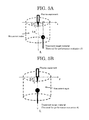
- FIG. 5A is a diagram explaining a positional relationship between a terminal for performance evaluation and plasma when evaluating atmospheric pressure plasma by measuring a current using the terminal for performance evaluation as an treatment target material.
- FIG. 5B is a diagram explaining a positional relationship between a terminal for performance evaluation to be measured along an axis and plasma.
- a plasma evaluation system of the present invention is mainly configured to precisely measure and objectively evaluate a current of an atmospheric pressure plasma and a small current having a low frequency or a high frequency flowing through a living body, etc., by employing a method of measuring a voltage across resistors incorporated on a current path as shown in FIG. 1 and evaluating a current based on the resistance values and a voltage value, and a method using a Rogowski coil or a current transformer.
- a treatment target material receives plasma generated by a plasma treatment equipment, the treatment target material is connected to a weak current measurement unit including a resistor unit and a differential amplifier via a treatment target side measurement terminal, and the weak current measurement unit is connected to a ground side of a plasma generation power source (PS), as shown in FIG. 2 .
- the plasma evaluation system evaluates a current by measuring a voltage across the resistors of the resistor unit through the differential amplifier. It is also possible to measure a change in an output voltage of the plasma generation power source, by using in combination a voltage measurement unit operating based on partial resistance.
- the ground side of the plasma generation power source is basically grounded, but may be used un-grounded.
- the resistors of the resistance unit are variable. Or, the resistance values are switchable.
- R1 is in a resistance value range of from 0.1 to about 1 [k ⁇ ]
- R2 and R3 are resistance values of about 50[ ⁇ ]
- R4 is a resistance value of about 5[ ⁇ ].
- Any electric signal such as an output from the differential amplifier is input as is to an analog-digital (AD) converter such as an oscilloscope, or transmitted through an analog optical converter and an optical fiber in an electrically insulated state, converted to an electric signal at a light receiving unit, and input to an analog-digital converter such as an oscilloscope.
- An output is displayed on a monitor unit of the oscilloscope.
- the data may also be connected to a personal computer and displayed on a monitor of the personal computer.
- the output from the oscilloscope may also be optically converted to be transmitted through an optical fiber in an electrically insulated state, and converted again to an electric signal to be displayed on a personal computer.
- the plasma generation power source is supplied with electricity from a power source such as a DC power source and a battery.
- a DC power source supplies electricity from an AC line through an isolation transformer.
- the differential amplifier, the optical converter (from electricity to light; E/O, and from light to electricity; O/E), the oscilloscope, the personal computer, the analog-digital converter, a computing unit, etc. described in the paragraph 0016 are also supplied with electricity from an AC line through an isolation transformer, respectively.
- the treatment target material shown in FIG. 2 is a terminal for performance evaluation (A)
- a current of each plasma treatment equipment is measured for performance evaluation.
- the treatment target material is a tray (B)
- a small-sized animal such as a mouse is put on the tray, and a current is measured from it.
- the treatment target material is an examination table (C)
- a current flowing through a middle-sized animal such as a human being is measured.
- the treatment target material is an electrode pad (D)
- a current flowing through a part of a human body (a hand, a foot, etc.) is measured.
- Treatment target materials such as A to D described above are provided as option members to be connected to the treatment target side measurement terminal of the evaluation system body.
- Treatment target materials such as A to D are selected from a metal, an insulating material (a dielectric material), etc.
- the shape of the terminal for performance evaluation (A) is selected from a flat plate, a sphere, a hemispherical concave, a sharp shape, etc.
- the shape of the treatment target material among a flat plate, a sphere, a hemispherical concave, a sharp shape, etc.
- a treatment target material having a sharp tip is electrically charged intensively at the tip, whereas a treatment target material having a concave surface has an extremely low charge density in the surface. Therefore, it is possible to evaluate plasma of the plasma treatment equipment under different electrical discharge conditions.
- a current through a Rogowski coil or a current transformer attached between the output of the resistor unit and the ground side of the plasma generation power source is also possible to measure a current through a Rogowski coil or a current transformer attached between the output of the resistor unit and the ground side of the plasma generation power source as shown in FIG. 3 .
- An output from the Rogowski coil and the current transformer is amplified by an amplifier and input to an analog-digital converter.
- a signal from an amplifier by optically converting it to transmit it through an optical fiber in an electrically insulated state, converting it to an electric signal at a light receiving unit, and inputting the electric signal to an analog-digital converter.
- Each amplifier is supplied with electricity from an AC line through an isolation transformer.
- plasma generated by a plasma treatment equipment is received by a treatment target material, and the treatment target material is connected to a ground side of a plasma generation power source via a treatment target side measurement terminal, as shown in FIG. 4 .
- a current can be measured through a Rogowski coil or a current transformer attached between the treatment target side measurement terminal and the ground side of the plasma generation power source.
- An example of plasma current evaluation will be described.
- a state of temporal changes of a current or a voltage is displayed.
- the analog-digital converter, the oscilloscope, and the personal computer include a computing function, they can calculate and display the true plasma current component flowed through a living body, etc. by eliminating a displacement current component generated by the plasma generation power source, etc.
- a specific method is based on the two diagrams described below, including a computing diagram A and a computing diagram B.
- Conditions for not generating plasma are set (e.g., when not flowing a gas, the plasma equipment is disconnected from the ground electrode).
- a voltage is applied to the plasma treatment equipment, and a voltage value V1 and a current value I1 are measured.
- Conditions for generating plasma are set (e.g., a gas is let to flow), and a voltage is applied to the plasma treatment equipment to generate plasma.
- the current value I1 of (1) is subtracted from the current value I3 of (3) (i.e., I3 ⁇ I1). In this way, the current component that has actually flowed through the living body, etc. is calculated.
- Conditions for not generating plasma is set (e.g., when not flowing a gas, the plasma equipment is disconnected from the ground electrode).
- a voltage is applied to the plasma treatment equipment, and a voltage value V1 and a current value I1 are measured.
- Conditions for generating plasma are set (e.g., a gas is let to flow), a voltage is applied to the plasma treatment equipment to generate plasma, and a voltage value V2 and a current value I2 are measured.
- FIG. 5A and FIG. 5B are diagrams explaining a plasma evaluation method for evaluating an atmospheric pressure plasma by measuring a current with the plasma evaluation system in which a terminal for performance evaluation is selectively employed as the treatment target material.
- a current of a plasma jet or a weak current flowing in the vicinity thereof during a plasma treatment was examined, and as a result, the following findings were obtained about the relative positional relationship between the plasma jet for atmospheric pressure plasma evaluation based on current measurement and the terminal for performance evaluation.
- a region from the plasma jet outlet of the plasma treatment equipment up to L0 is within the plasma jet (0 ⁇ L1 ⁇ L0), and this region is influenced the most by the plasma jet.
- the plasma treatment is performed within this range. Therefore, this region is the most important for evaluating the plasma.
- a region from the tip of the plasma jet up to a distance of 2L0 (L0 ⁇ L1 ⁇ 3L0) is relatively close to the plasma jet extending by a length of L0, and the influence of the plasma jet (a current passed through the plasma jet) cannot be ignored up to this distance.
- Information of a current in the vicinity of the plasma jet can be obtained from outside the plasma jet.
- the plasma jet has a certain diameter, which however is much smaller than L0. Therefore, the plasma jet can be regarded as a line.
- Information of a current in the vicinity of the plasma jet can be obtained from outside the plasma jet. Since the treatment target terminal for performance evaluation has a size, it may be necessary to shift the direction of the plasma jet to some degree. Even in such a case, the reach of the influence of the plasma jet falls within the range of 0 ⁇ r1 ⁇ 2L0 from the axis.
- a circular columnar region having a radius of L0 ⁇ 2 and a height of L0 ⁇ 3 is assumed (represented by a dotted line in the drawings), where L0 is the length of the plasma generated by the plasma treatment equipment.
- Plasma treatment is applied along the center axis of the circular column from the center of the upper base of the circular column toward the lower base thereof.
- it is possible to evaluate the atmospheric pressure plasma by measuring a current by selecting a measuring position appropriately within the range of the circular columnar region or by shifting the measuring position within the range of the circular columnar region. For example, it is possible to evaluate the optimum state of the plasma treatment equipment, by applying this system to the equipment before use.
- an evaluation system which has a function of monitoring a treatment state when the plasma treatment equipment is used during a plasma treatment, or the performance of the treatment equipment before a treatment or during a treatment.
- the plasma evaluation system can measure current values generated by plasma treatment equipment, it is possible, for, for example, medical purposes, to give an evaluation to, for example, take a measure of limiting the output when the current value exceeds a certain value.
- the present invention can easily measure current components generated by various plasma treatment equipments, and can objectively evaluate the difference between the currents of the equipments.
- the present invention is suitable for measuring medical plasma treatment equipments. Further, when a plasma treatment equipment is used on site such as a factory, by objectively evaluating the state of the plasma treatment equipment, it is possible to perform measurement on site, or perform measurement for maintenance, or objectively judge whether the cause of any trouble is attributable to the plasma equipment or to any other factor.
Landscapes
- Health & Medical Sciences (AREA)
- Engineering & Computer Science (AREA)
- Life Sciences & Earth Sciences (AREA)
- Biomedical Technology (AREA)
- Surgery (AREA)
- Plasma & Fusion (AREA)
- Physics & Mathematics (AREA)
- Public Health (AREA)
- Nuclear Medicine, Radiotherapy & Molecular Imaging (AREA)
- Animal Behavior & Ethology (AREA)
- General Health & Medical Sciences (AREA)
- Veterinary Medicine (AREA)
- Otolaryngology (AREA)
- Heart & Thoracic Surgery (AREA)
- Medical Informatics (AREA)
- Molecular Biology (AREA)
- Spectroscopy & Molecular Physics (AREA)
- Pathology (AREA)
- Radiology & Medical Imaging (AREA)
- Plasma Technology (AREA)
Applications Claiming Priority (3)
| Application Number | Priority Date | Filing Date | Title |
|---|---|---|---|
| JP2011-254516 | 2011-11-22 | ||
| JP2011254516 | 2011-11-22 | ||
| PCT/JP2012/077258 WO2013077126A1 (ja) | 2011-11-22 | 2012-10-22 | プラズマ評価装置 |
Publications (2)
| Publication Number | Publication Date |
|---|---|
| US20140312241A1 US20140312241A1 (en) | 2014-10-23 |
| US9254397B2 true US9254397B2 (en) | 2016-02-09 |
Family
ID=48469577
Family Applications (1)
| Application Number | Title | Priority Date | Filing Date |
|---|---|---|---|
| US14/359,970 Active US9254397B2 (en) | 2011-11-22 | 2012-10-22 | Plasma evaluation apparatus |
Country Status (4)
| Country | Link |
|---|---|
| US (1) | US9254397B2 (ja) |
| EP (1) | EP2782430B1 (ja) |
| JP (1) | JP6074792B2 (ja) |
| WO (1) | WO2013077126A1 (ja) |
Families Citing this family (4)
| Publication number | Priority date | Publication date | Assignee | Title |
|---|---|---|---|---|
| JP6399852B2 (ja) * | 2014-08-07 | 2018-10-03 | フクダ電子株式会社 | 脈波測定装置及び生体情報測定装置 |
| US9711252B1 (en) * | 2014-10-28 | 2017-07-18 | Michelle Corning | High energy beam diffraction material treatment system |
| JP6664046B2 (ja) * | 2016-03-07 | 2020-03-13 | 国立研究開発法人産業技術総合研究所 | プラズマ照射処理装置、その評価装置及び評価方法、その制御装置及び制御方法、並びに、膜の製造方法 |
| JP6713532B2 (ja) * | 2016-05-13 | 2020-06-24 | 株式会社Fuji | 医療用プラズマ発生装置、およびプラズマ照射方法 |
Citations (7)
| Publication number | Priority date | Publication date | Assignee | Title |
|---|---|---|---|---|
| JPH0675070A (ja) | 1992-08-26 | 1994-03-18 | Hitachi Ltd | 核融合装置とそのプラズマ制御方法及び制御装置 |
| US5735846A (en) | 1994-06-27 | 1998-04-07 | Ep Technologies, Inc. | Systems and methods for ablating body tissue using predicted maximum tissue temperature |
| JP2002523173A (ja) | 1998-09-01 | 2002-07-30 | ハインツ リンデンマイヤー、 | 生体組織の処置用のプラズマアークを発生する高周波装置 |
| US20050263247A1 (en) | 2004-05-28 | 2005-12-01 | Semiconductor Technology Academic Research Center | Plasma processing apparatus and plasma processing method |
| JP2007222687A (ja) | 1994-06-27 | 2007-09-06 | Boston Scientific Ltd | 監視制御予測温度の利用による生体組織加熱アブレーションシステム及び方法 |
| US20100231194A1 (en) * | 2009-03-10 | 2010-09-16 | Hartmut Bauch | Method and device for monitoring plasma discharges |
| WO2012005132A1 (ja) | 2010-07-07 | 2012-01-12 | 独立行政法人産業技術総合研究所 | プラズマ照射処理装置 |
Family Cites Families (7)
| Publication number | Priority date | Publication date | Assignee | Title |
|---|---|---|---|---|
| JPS59135474U (ja) * | 1983-02-28 | 1984-09-10 | 富士通株式会社 | 電流測定装置 |
| JP3149272B2 (ja) * | 1991-12-10 | 2001-03-26 | 幸子 岡崎 | 大気圧グロー放電プラズマのモニター方法 |
| JP3068052B2 (ja) * | 1998-04-06 | 2000-07-24 | 株式会社メックス | 電気外科装置 |
| JP4242737B2 (ja) * | 2003-09-02 | 2009-03-25 | ナノフォトン株式会社 | レーザ治療装置及び細胞破壊方法 |
| JP2005147125A (ja) * | 2003-10-20 | 2005-06-09 | Toyota Motor Corp | プラズマリアクター用電源回路 |
| US7601619B2 (en) * | 2005-04-04 | 2009-10-13 | Panasonic Corporation | Method and apparatus for plasma processing |
| WO2007083681A1 (ja) * | 2006-01-20 | 2007-07-26 | Kyushu University, National University Corporation | カーボンナノ材料の可溶化方法 |
-
2012
- 2012-10-22 WO PCT/JP2012/077258 patent/WO2013077126A1/ja not_active Ceased
- 2012-10-22 US US14/359,970 patent/US9254397B2/en active Active
- 2012-10-22 EP EP12851481.7A patent/EP2782430B1/en not_active Not-in-force
- 2012-10-24 JP JP2012234839A patent/JP6074792B2/ja not_active Expired - Fee Related
Patent Citations (10)
| Publication number | Priority date | Publication date | Assignee | Title |
|---|---|---|---|---|
| JPH0675070A (ja) | 1992-08-26 | 1994-03-18 | Hitachi Ltd | 核融合装置とそのプラズマ制御方法及び制御装置 |
| US5735846A (en) | 1994-06-27 | 1998-04-07 | Ep Technologies, Inc. | Systems and methods for ablating body tissue using predicted maximum tissue temperature |
| JP2007222687A (ja) | 1994-06-27 | 2007-09-06 | Boston Scientific Ltd | 監視制御予測温度の利用による生体組織加熱アブレーションシステム及び方法 |
| JP2002523173A (ja) | 1998-09-01 | 2002-07-30 | ハインツ リンデンマイヤー、 | 生体組織の処置用のプラズマアークを発生する高周波装置 |
| US6565558B1 (en) | 1998-09-01 | 2003-05-20 | Heinz Lindenmeier | High-frequency device for generating a plasma arc for the treatment of biological tissue |
| US20050263247A1 (en) | 2004-05-28 | 2005-12-01 | Semiconductor Technology Academic Research Center | Plasma processing apparatus and plasma processing method |
| JP2005340632A (ja) | 2004-05-28 | 2005-12-08 | Handotai Rikougaku Kenkyu Center:Kk | プラズマ処理装置およびプラズマ処理方法 |
| US20100231194A1 (en) * | 2009-03-10 | 2010-09-16 | Hartmut Bauch | Method and device for monitoring plasma discharges |
| WO2012005132A1 (ja) | 2010-07-07 | 2012-01-12 | 独立行政法人産業技術総合研究所 | プラズマ照射処理装置 |
| US20130204244A1 (en) | 2010-07-07 | 2013-08-08 | Hajime Sakakita | Plasma treatment equipment |
Non-Patent Citations (3)
| Title |
|---|
| Extended European Search Report dated May 29, 2015, for corresponding European Patent Application No. EP 12 85 1481. |
| Grund et al., "Endoscopic Argon Plasma Coagulation (APC) First Clinical Experiences in Flexible Endoscopy", End. Surg., 1994, pp. 42-46, vol. 2, Georg Thieme Verlag Stuttgart, New York. |
| International Search Report dated Jan. 22, 2013, for corresponding International Patent Application No. PCT/JP2012/077258. |
Also Published As
| Publication number | Publication date |
|---|---|
| EP2782430A4 (en) | 2015-07-01 |
| WO2013077126A1 (ja) | 2013-05-30 |
| EP2782430A1 (en) | 2014-09-24 |
| EP2782430B1 (en) | 2016-08-03 |
| JP6074792B2 (ja) | 2017-02-08 |
| JP2013131487A (ja) | 2013-07-04 |
| US20140312241A1 (en) | 2014-10-23 |
Similar Documents
| Publication | Publication Date | Title |
|---|---|---|
| US9254397B2 (en) | Plasma evaluation apparatus | |
| Litvak et al. | Experimental studies of high-frequency azimuthal waves in Hall thrusters | |
| EP2436326B1 (en) | Real-time ARC control in electrosurgical generators | |
| KR101345640B1 (ko) | 다중 건식전극을 포함하는 생체 임피던스 측정 센서 및 이를 포함하는 센서 모듈, 생체 임피던스 측정 시스템, 및 생체 임피던스 측정 방법 | |
| WO2009006152A3 (en) | Method and apparatus for a voltage/current probe test arrangements | |
| CN101170865A (zh) | 等离子体悬浮参考探针 | |
| CN106443237B (zh) | 电动汽车的高低压系统隔离度的测试方法和装置 | |
| EP3912583B1 (en) | Testing electrode quality | |
| TWI794845B (zh) | 一種射頻系統狀態受控的半導體設備 | |
| CN103190908A (zh) | 手持式电阻抗测量仪 | |
| US20230305045A1 (en) | System and method for non-invasive sensing of radio-frequency current spectra flowing in a plasma processing chamber | |
| Kim et al. | Wireless electric field sensor with adaptive voltage gain for measuring an electrical potential treatment chair | |
| Jaimes | Development and testing of a customizable and portable bioimpedance spectroscopy meter (BioZspectra-v1) | |
| EP3912584B1 (en) | Detecting asymmetry in a bidirectional semiconductor device | |
| CZ2011890A3 (cs) | Zpusob merení iontové distribucní funkce v nízkoteplotním plazmatu, merící systém pro provádení tohoto zpusobu a sonda pro merící systém | |
| Vallicelli et al. | Mixed-Signal Ionoacoustic Analog Front-End for Proton Range Verification with $24\\mu\mathrm {m} $ Precision at 0.8 Gy Bragg Peak Dose | |
| Haller et al. | Short-and longtime stability of therapeutic ultrasound reference sources for dosimetry and exposimetry purposes | |
| US20240053385A1 (en) | Eeg impedance test circuit, method, and device | |
| CN121633605A (zh) | 肿瘤电场治疗系统及其交变电信号检测电路 | |
| Mazurek et al. | Analysis of electrical and magnetic fields in ELF band from plasma reactor installations | |
| Ivanov et al. | Electron temperature fluctuation measurements with high temporal resolution in the TEXTOR boundary plasma | |
| CN121633606A (zh) | 肿瘤电场治疗系统及其交变电信号检测电路 | |
| CZ23356U1 (cs) | Měřicí systém pro měření iontové distribuční funkce v nízkoteplotním plazmatu a sonda pro měřicí systém | |
| KR102254776B1 (ko) | 고정밀 임피던스 측정 장치 | |
| CN120802328A (zh) | 电流电荷转换器及加速器束诊系统 |
Legal Events
| Date | Code | Title | Description |
|---|---|---|---|
| AS | Assignment |
Owner name: NATIONAL INSTITUTE OF ADVANCED INDUSTRIAL SCIENCE Free format text: ASSIGNMENT OF ASSIGNORS INTEREST;ASSIGNORS:SAKAKITA, HAJIME;IKEHARA, YUZURU;KIYAMA, SATORU;SIGNING DATES FROM 20140508 TO 20140513;REEL/FRAME:033087/0283 |
|
| FEPP | Fee payment procedure |
Free format text: PAYOR NUMBER ASSIGNED (ORIGINAL EVENT CODE: ASPN); ENTITY STATUS OF PATENT OWNER: LARGE ENTITY |
|
| STCF | Information on status: patent grant |
Free format text: PATENTED CASE |
|
| MAFP | Maintenance fee payment |
Free format text: PAYMENT OF MAINTENANCE FEE, 4TH YEAR, LARGE ENTITY (ORIGINAL EVENT CODE: M1551); ENTITY STATUS OF PATENT OWNER: LARGE ENTITY Year of fee payment: 4 |
|
| MAFP | Maintenance fee payment |
Free format text: PAYMENT OF MAINTENANCE FEE, 8TH YEAR, LARGE ENTITY (ORIGINAL EVENT CODE: M1552); ENTITY STATUS OF PATENT OWNER: LARGE ENTITY Year of fee payment: 8 |