US9246422B2 - Motor control device and motor control method - Google Patents
Motor control device and motor control method Download PDFInfo
- Publication number
- US9246422B2 US9246422B2 US14/012,574 US201314012574A US9246422B2 US 9246422 B2 US9246422 B2 US 9246422B2 US 201314012574 A US201314012574 A US 201314012574A US 9246422 B2 US9246422 B2 US 9246422B2
- Authority
- US
- United States
- Prior art keywords
- energization pattern
- rotor
- rotation speed
- motor
- motor control
- Prior art date
- Legal status (The legal status is an assumption and is not a legal conclusion. Google has not performed a legal analysis and makes no representation as to the accuracy of the status listed.)
- Active, expires
Links
Images


Classifications
-
- H02P6/145—
-
- H—ELECTRICITY
- H02—GENERATION; CONVERSION OR DISTRIBUTION OF ELECTRIC POWER
- H02P—CONTROL OR REGULATION OF ELECTRIC MOTORS, ELECTRIC GENERATORS OR DYNAMO-ELECTRIC CONVERTERS; CONTROLLING TRANSFORMERS, REACTORS OR CHOKE COILS
- H02P6/00—Arrangements for controlling synchronous motors or other dynamo-electric motors using electronic commutation dependent on the rotor position; Electronic commutators therefor
- H02P6/14—Electronic commutators
- H02P6/15—Controlling commutation time
- H02P6/153—Controlling commutation time wherein the commutation is advanced from position signals phase in function of the speed
-
- H—ELECTRICITY
- H02—GENERATION; CONVERSION OR DISTRIBUTION OF ELECTRIC POWER
- H02P—CONTROL OR REGULATION OF ELECTRIC MOTORS, ELECTRIC GENERATORS OR DYNAMO-ELECTRIC CONVERTERS; CONTROLLING TRANSFORMERS, REACTORS OR CHOKE COILS
- H02P27/00—Arrangements or methods for the control of AC motors characterised by the kind of supply voltage
- H02P27/04—Arrangements or methods for the control of AC motors characterised by the kind of supply voltage using variable-frequency supply voltage, e.g. inverter or converter supply voltage
- H02P27/06—Arrangements or methods for the control of AC motors characterised by the kind of supply voltage using variable-frequency supply voltage, e.g. inverter or converter supply voltage using dc to ac converters or inverters
- H02P27/08—Arrangements or methods for the control of AC motors characterised by the kind of supply voltage using variable-frequency supply voltage, e.g. inverter or converter supply voltage using dc to ac converters or inverters with pulse width modulation
-
- H—ELECTRICITY
- H02—GENERATION; CONVERSION OR DISTRIBUTION OF ELECTRIC POWER
- H02P—CONTROL OR REGULATION OF ELECTRIC MOTORS, ELECTRIC GENERATORS OR DYNAMO-ELECTRIC CONVERTERS; CONTROLLING TRANSFORMERS, REACTORS OR CHOKE COILS
- H02P6/00—Arrangements for controlling synchronous motors or other dynamo-electric motors using electronic commutation dependent on the rotor position; Electronic commutators therefor
- H02P6/14—Electronic commutators
-
- Y—GENERAL TAGGING OF NEW TECHNOLOGICAL DEVELOPMENTS; GENERAL TAGGING OF CROSS-SECTIONAL TECHNOLOGIES SPANNING OVER SEVERAL SECTIONS OF THE IPC; TECHNICAL SUBJECTS COVERED BY FORMER USPC CROSS-REFERENCE ART COLLECTIONS [XRACs] AND DIGESTS
- Y02—TECHNOLOGIES OR APPLICATIONS FOR MITIGATION OR ADAPTATION AGAINST CLIMATE CHANGE
- Y02P—CLIMATE CHANGE MITIGATION TECHNOLOGIES IN THE PRODUCTION OR PROCESSING OF GOODS
- Y02P80/00—Climate change mitigation technologies for sector-wide applications
- Y02P80/10—Efficient use of energy, e.g. using compressed air or pressurized fluid as energy carrier
Definitions
- the present invention relates to a motor control device and a motor control method which can optimize efficiency according to a rotation speed of an electric motor.
- the brushless motor includes a plurality of Hall elements, and detects a rotation position of a rotor, using a signal output from the Hall elements.
- the energization pattern of the stator coils in the brushless motor is determined according to a rotation position of the rotor.
- the energization pattern is a pattern indicating the stator coil connected to the power supply according to the rotation position of the rotor as well as a direction of the current that flows through the stator coil connected to the power supply.
- the stator coils are energized according to a predetermined energization pattern depending on the rotation position of the rotor.
- the energization pattern of the stator coils changes simultaneously with the change of a signal output from one of the plurality of Hall elements.
- timing of change of the signals output from the Hall elements becomes quick as the rotation speed of the rotor decreases.
- the invention has been made for overcoming the above disadvantages of the past, and a purpose of the invention is to provide a motor control device and a motor control method that can optimize efficiency according to a rotation speed of the motor.
- the motor control device includes an energization pattern output portion and an inverter circuit.
- the energization pattern output portion cyclically outputs a plurality of energization patterns.
- the inverter circuit selectively connects respective coils provided in the motor to a power supply according to the output energization pattern.
- the energization pattern output portion delays the output timing of the energization pattern according to a rotation speed of the motor.
- the motor control device delays switching of a present energization pattern to a next energization pattern as the rotation speed of the motor decreases, and thereby rotates the motor with optimum efficiency according to the rotation speed.
- a motor control method includes a first stage that selects an energization pattern according to a rotation position of a rotor of a motor, a second stage that calculates a rotation speed of the rotor, a third stage that calculates a delay time from the rotation speed of the rotor and a fourth stage that outputs the selected energization pattern with a delay of the calculated delay time, and continuously rotates the motor while repeating the first to fourth stages.
- the motor control method according to the invention delays switching from a present energization pattern to a next energization pattern as a rotation speed of a motor decreases, and rotates the motor with optimum efficiency according to the rotation speed.
- the invention configured as described above delays the output timing of the energization pattern according to the rotation speed of the motor, and therefore can optimize the efficiency according to the rotation speed.
- FIG. 4 illustrates a relationship between energization patterns and the signals output from the sensor portions
- FIG. 5 illustrates a relationship between the energization patterns and energization directions of the stator coils
- FIG. 6 illustrates output timing of the energization patterns
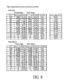
- FIG. 8 illustrates characteristics of a past motor control device and a measurement result of characteristics of the motor control device according to the embodiment
- FIG. 9 is a graph visualizing the measurement result of FIG. 8 .
- FIG. 10 is a current waveform diagram obtained when the past motor control device and the motor control device according to the embodiment drive the same motor under the same conditions.
- the rectifier circuit 110 includes six bridge-connected diodes D 1 -D 6 as illustrated in the figure, and the six diodes D 1 -D 6 perform full-wave rectification on a current flowing from an AC (3-phase) power supply 120 .
- the smoothing capacitor C smoothes the current subjected to the full-wave rectification by the six diodes D 1 -D 6 so that the ripple in the DC current subjected to the full-wave rectification decreases.
- the rectifier circuit 110 is a power supply of the motor M.
- the three arm circuits 140 A, 140 B and 140 C are connected in parallel to the smoothing capacitor C of the rectifier circuit 110 .
- a diode D is reversely connected between a collector and an emitter of each of six transistors TR 1 , TR 4 , TR 2 , TR 5 , TR 3 and TR 6 .
- Drive circuits 145 are individually connected to the gates of these six transistors TR 1 , TR 4 , TR 2 , TR 5 , TR 3 and TR 6 for switching these transistors, respectively.
- the motor control device 100 includes an energization pattern output portion 150 connected to the sensor portions H 1 , H 2 and H 3 .
- the energization pattern output portion 150 cyclically outputs a plurality of energization patterns to each drive circuit 145 .
- the energization pattern output portion 150 delays the output timing of the energization pattern according to the rotation speed of the motor M. More specifically, the energization pattern output portion 150 delays the output timing of the energization pattern by a longer time as the rotation speed of the motor M decreases.
- the inverter circuit 130 selectively connects the stator coils Lu, Lv and Lw provided in the motor M to the rectifier circuit 110 according to the energization pattern.
- the rotation speed calculating portion 152 calculates the rotation speed of the rotor MR based on the pulse signal output from the sensor portions H 1 , H 2 and H 3 .
- the delay time calculating portion 154 calculates the delay time for delaying the output timing of the energization pattern according to the rotation speed of the calculated rotation speed of the rotor MR.
- the delay time calculating portion 154 includes a table describing the rotation speed of the rotor MR and the delay time corresponding to the rotation speed.
- the delay time is 0 when the rotor MR rotates at a rated rotation speed, and increases by t msec every time it decreases from the rated rotation speed by a predetermined rate. Therefore, the delay time calculating portion 154 increases stepwise the delay time as the rotation speed of the rotor MR decreases from the rated rotation speed.
- Each of the three sensor portions H 1 , H 2 and H 3 outputs, as illustrated in FIG. 3 , the Hi or Lo signal depending on the rotation position of the rotor MR, respectively.
- the energization pattern selecting portion 156 receives the Hi and Lo signals output from each of the three sensor portions H 1 , H 2 and H 3 , and recognizes the rotation position's of the rotor MR. Since each of the three sensor portions H 1 , H 2 and H 3 outputs the Hi and Lo signals phase shifted by 120° in electrical angle from each other, the energization pattern selecting portion 156 can recognize the rotation position of the rotor MR at every 60°.
- the energization pattern selecting portion 156 selects, for example, the energization pattern 1 when the sensor portions H 1 , H 2 and H 3 output the Lo, Lo and Hi signals, respectively. Also, the energization pattern selecting portion 156 selects the energization pattern 4 when the sensor portions H 1 , H 2 and H 3 output the Hi, Hi and Lo signals, respectively.
- the combinations of the Hi and Lo signals output from the three sensor portions H 1 , H 2 and H 3 can exhibit six patterns as illustrated in FIG. 4 .
- the energization patterns 1-6 are set corresponding to these six patterns, respectively. Therefore, the energization pattern selecting portion 156 can select the energization pattern corresponding to the rotation position of the rotor MR by recognizing the rotation position of the rotor MR detected by the three sensor portions H 1 , H 2 and H 3 .
- the energization pattern transits in the order of 1, 2, 3, 4, 5, 6, 1, 2 . . . .
- the energization pattern proceeds from 1-6, the rotor MR makes one rotation. Consequently, the energization pattern selecting portion 156 circularly selects the energization patterns 1-6 every time the rotor MR makes one rotation.
- FIG. 5 illustrates a relationship between the energization pattern and the energization direction of the stator coil.
- the drive circuit 145 performs the switching of the transistors TR 1 and TR 5 illustrated in FIG. 1 to flow the current through a closed circuit extending from the rectifier circuit 110 through the transistor TR 1 , the stator coil Lu, the stator coil Lw and the transistor TR 5 to the rectifier circuit 110 .
- the drive circuit 145 performs the switching of the transistors TR 1 and TR 6 to flow the current through a closed circuit extending from the rectifier circuit 110 through the transistor TR 1 , the stator coil Lu, the stator coil Lv and the transistor TR 6 to the rectifier circuit 110 . Further, when the energization pattern 3 is output from the energization pattern output timing adjusting portion 158 , it exhibits the energization directions of V+ and W ⁇ .
- the drive circuit 145 performs the switching of the transistors TR 2 and TR 6 to flow the current through a closed circuit extending from the rectifier circuit 110 through the transistor TR 2 , the stator coil Lw, the stator coil Lv and the transistor TR 6 to the rectifier circuit 110 .
- the current flows through a closed circuit formed in the substantially same manner as the energization patterns 1-3.
- the drive circuit 145 performs the PWM control on the transistors forming the closed circuit.
- the energization pattern output timing adjusting portion 158 delays the energization pattern selected by the energization pattern selecting portion 156 by a delay time calculated by the delay time calculating portion 154 , and then outputs it to the inverter circuit 130 .
- the instruction for the energization pattern 2 is output to the drive circuit 145 without a delay.
- the rotation speed of the rotor MR is medium, the instruction for the energization pattern 2 is output to the drive circuit 145 with a delay of t1 msec.
- the instruction for the energization pattern 2 is output to the drive circuit 145 with a delay by t2 msec. Similar manners are employed when switching the energization pattern from 2-3 and the like.
- FIG. 7 is an operation flowchart of the motor control device 100 .
- the processing procedure in this operation flowchart represents a procedure of the motor control method.
- the energization pattern selecting portion 156 selects the energization pattern from the signals provided of the three sensor portions H 1 , H 2 and H 3 .
- the combination of the signals of the three sensor portions H 1 , H 2 and H 3 represents the rotation position of the rotor MR, and consequently the energization pattern selecting portion 156 selects the energization pattern according to the rotation position of the rotor MR (step S 100 ).
- the rotation speed calculating portion 152 calculates the rotation speed of the rotor MR (motor M) based on the pulse signals output from the three sensor portions H 1 , H 2 and H 3 (step S 101 ).
- the delay time calculating portion 154 calculates a delay time for adjusting the timing of outputting the energization pattern based on the rotation speed of the rotor MR (motor M) calculated by the rotation speed calculating portion 152 (step S 102 ).
- the energization pattern output timing adjusting portion 158 outputs the energization pattern selected by the energization pattern selecting portion 156 by a delay time calculated by the delay time calculating portion 154 .
- a delay time calculated by the delay time calculating portion 154 .
- the rotor MR rotates at a medium speed
- it outputs the energization pattern with a delay of t1 msec as compared with the case of the high speed.
- the rotor MR rotates at a low speed
- it outputs the energization pattern with a delay of t2 msec as compared with the case of the high speed.
- the switching of the energization pattern by the inverter circuit 130 delays so that it is possible to eliminate the errors in detection timing of the sensor portions H 1 , H 2 and H 3 (step S 103 ).
- the motor control device 100 intentionally delays the timing of switching the energization pattern when the rotation speed of the motor is low. Therefore, it is possible to overcome easily such a disadvantage that the energization pattern is switched early when the motor rotation speed is low, as compared with the case of the high rotation speed.
- FIG. 8 illustrates measurement results of the characteristics of the past motor control device and those of the motor control device according to the embodiment.
- FIG. 9 is a graph visualizing the measurement results in FIG. 8 .
- the measurements of the characteristics of the motor control device are performed on fan motors of a type in which the two fan motors are connected in series and are operated at different rotation speeds for blowing, respectively.
- the fan motor on the front stage is positioned on an upstream side in the blowing direction of the fan motor, and the fan motor on the rear stage is positioned on a downstream side in the blowing direction.
- the electric power reduction ratios of the motors on the front and rear stages increase in accordance with the change from the state in which a duty ratio is large and thus the motor rotates at high speed to the state in which the duty ratio is small and thus the motor rotates at low speed. Therefore, when the rotation speed is uniform, the motor control device according to the embodiment can reduce the current flowing through the stator coils as compared with the past motor control device. Accordingly, the power consumption with respect to the output of the motor can be small. Particularly, as illustrated in FIG. 9 , it can be understood that the shifting of the output timing of the energization pattern significantly raises the efficiency in the middle-speed range.
- FIG. 10 is a current waveform diagram illustrating the cases where the past motor control device and the motor control device according to the embodiment drive the same motor, respectively.
- the embodiment including the three-phase motor is described by way of example, the concept of the invention can be applied to various kinds of motors of different phases such as single-phase, 2-phase and 5-phase motors.
- the embodiment is described in connection with an example of the rotor having two poles, the concept of the invention can likewise be applied to motors having three or more poles. Further, it can be applied to motors of various numbers of slots.
Applications Claiming Priority (2)
| Application Number | Priority Date | Filing Date | Title |
|---|---|---|---|
| JP2012196322A JP2014054058A (ja) | 2012-09-06 | 2012-09-06 | モータ制御装置及びモータ制御方法 |
| JP2012-196322 | 2012-09-06 |
Publications (2)
| Publication Number | Publication Date |
|---|---|
| US20140062360A1 US20140062360A1 (en) | 2014-03-06 |
| US9246422B2 true US9246422B2 (en) | 2016-01-26 |
Family
ID=49080749
Family Applications (1)
| Application Number | Title | Priority Date | Filing Date |
|---|---|---|---|
| US14/012,574 Active 2034-03-23 US9246422B2 (en) | 2012-09-06 | 2013-08-28 | Motor control device and motor control method |
Country Status (5)
| Country | Link |
|---|---|
| US (1) | US9246422B2 (ja) |
| EP (1) | EP2706656B1 (ja) |
| JP (1) | JP2014054058A (ja) |
| CN (1) | CN103684123A (ja) |
| TW (1) | TWI600269B (ja) |
Families Citing this family (6)
| Publication number | Priority date | Publication date | Assignee | Title |
|---|---|---|---|---|
| TWI473415B (zh) * | 2012-04-10 | 2015-02-11 | Padauk Technology Co Ltd | 可提高馬達驅動運轉效率之控制器與方法 |
| US9325262B2 (en) * | 2014-04-09 | 2016-04-26 | Woodward, Inc. | Brushless motors with linear hall sensors |
| JP6357996B2 (ja) * | 2014-09-12 | 2018-07-18 | アイシン精機株式会社 | インバータ装置 |
| WO2017208873A1 (ja) * | 2016-06-03 | 2017-12-07 | パナソニックIpマネジメント株式会社 | モータ駆動装置および、これを用いた圧縮機を有する電気機器 |
| US11888423B2 (en) * | 2021-10-26 | 2024-01-30 | Infineon Technologies Ag | Voltage modulation for controlling a motor |
| WO2023107976A1 (en) * | 2021-12-09 | 2023-06-15 | Milwaukee Electric Tool Corporation | Twelve-step dynamic commutation for an electric motor |
Citations (13)
| Publication number | Priority date | Publication date | Assignee | Title |
|---|---|---|---|---|
| US4988939A (en) * | 1989-08-04 | 1991-01-29 | Thor Technology Corporation | Electric motor with variable commutation delay |
| US5206567A (en) * | 1990-08-28 | 1993-04-27 | Kabushiki Kaisha Toshiba | Apparatus for reliably activating sensorless and brushless DC motor |
| US5495163A (en) * | 1993-05-12 | 1996-02-27 | Sundstrand Corporation | Control for a brushless generator operable in generating and starting modes |
| WO1996010863A1 (en) | 1994-09-30 | 1996-04-11 | Itt Automotive Electrical Systems, Inc. | Dual mode controller for a brushless dc motor |
| US5703449A (en) * | 1990-10-19 | 1997-12-30 | Seiko Epson Corporation | Controller for brushless DC motor without position sensor |
| US5767643A (en) * | 1996-02-02 | 1998-06-16 | Siliconix Incorporated | Commutation delay generator for a multiphase brushless DC motor |
| JP2000134978A (ja) | 1998-08-20 | 2000-05-12 | Calsonic Corp | ブラシレスモ―タ |
| JP2001145381A (ja) | 1999-11-12 | 2001-05-25 | Toyota Motor Corp | モータの制御装置 |
| JP2002191186A (ja) | 2000-12-20 | 2002-07-05 | Namiki Precision Jewel Co Ltd | ブラシレスモータ制御装置およびブラシレスモータのステップ制御方法 |
| US6586898B2 (en) * | 2001-05-01 | 2003-07-01 | Magnon Engineering, Inc. | Systems and methods of electric motor control |
| JP2005245076A (ja) | 2004-02-25 | 2005-09-08 | Minebea Co Ltd | ブラシレスdcモータの制御装置 |
| US7053573B2 (en) * | 2004-01-29 | 2006-05-30 | Sanyo Electric Co., Ltd. | Motor drive apparatus, integrated circuit, and motor drive method |
| US8159164B2 (en) * | 2009-02-20 | 2012-04-17 | Sunonwealth Electric Machine Industry Co., Ltd. | Variable-delay-time control system for a motor |
Family Cites Families (5)
| Publication number | Priority date | Publication date | Assignee | Title |
|---|---|---|---|---|
| JP2001037258A (ja) * | 1999-07-23 | 2001-02-09 | Toshiba Corp | インバータ装置 |
| JP3544338B2 (ja) * | 2000-03-23 | 2004-07-21 | シャープ株式会社 | 圧縮機モータの制御装置 |
| JP3789843B2 (ja) * | 2002-03-29 | 2006-06-28 | 三洋電機株式会社 | ブラシレスモータの回転数制御方法及びこれを用いた洗濯機 |
| JP2006060941A (ja) * | 2004-08-20 | 2006-03-02 | Asmo Co Ltd | ブラシレスモータ |
| JP2012152033A (ja) * | 2011-01-19 | 2012-08-09 | Aisin Seiki Co Ltd | センサレスブラシレスモータの駆動装置 |
-
2012
- 2012-09-06 JP JP2012196322A patent/JP2014054058A/ja active Pending
-
2013
- 2013-08-28 US US14/012,574 patent/US9246422B2/en active Active
- 2013-08-30 EP EP13182358.5A patent/EP2706656B1/en active Active
- 2013-09-02 CN CN201310392366.3A patent/CN103684123A/zh active Pending
- 2013-09-05 TW TW102132003A patent/TWI600269B/zh active
Patent Citations (13)
| Publication number | Priority date | Publication date | Assignee | Title |
|---|---|---|---|---|
| US4988939A (en) * | 1989-08-04 | 1991-01-29 | Thor Technology Corporation | Electric motor with variable commutation delay |
| US5206567A (en) * | 1990-08-28 | 1993-04-27 | Kabushiki Kaisha Toshiba | Apparatus for reliably activating sensorless and brushless DC motor |
| US5703449A (en) * | 1990-10-19 | 1997-12-30 | Seiko Epson Corporation | Controller for brushless DC motor without position sensor |
| US5495163A (en) * | 1993-05-12 | 1996-02-27 | Sundstrand Corporation | Control for a brushless generator operable in generating and starting modes |
| WO1996010863A1 (en) | 1994-09-30 | 1996-04-11 | Itt Automotive Electrical Systems, Inc. | Dual mode controller for a brushless dc motor |
| US5767643A (en) * | 1996-02-02 | 1998-06-16 | Siliconix Incorporated | Commutation delay generator for a multiphase brushless DC motor |
| JP2000134978A (ja) | 1998-08-20 | 2000-05-12 | Calsonic Corp | ブラシレスモ―タ |
| JP2001145381A (ja) | 1999-11-12 | 2001-05-25 | Toyota Motor Corp | モータの制御装置 |
| JP2002191186A (ja) | 2000-12-20 | 2002-07-05 | Namiki Precision Jewel Co Ltd | ブラシレスモータ制御装置およびブラシレスモータのステップ制御方法 |
| US6586898B2 (en) * | 2001-05-01 | 2003-07-01 | Magnon Engineering, Inc. | Systems and methods of electric motor control |
| US7053573B2 (en) * | 2004-01-29 | 2006-05-30 | Sanyo Electric Co., Ltd. | Motor drive apparatus, integrated circuit, and motor drive method |
| JP2005245076A (ja) | 2004-02-25 | 2005-09-08 | Minebea Co Ltd | ブラシレスdcモータの制御装置 |
| US8159164B2 (en) * | 2009-02-20 | 2012-04-17 | Sunonwealth Electric Machine Industry Co., Ltd. | Variable-delay-time control system for a motor |
Non-Patent Citations (1)
| Title |
|---|
| Japanese Office Action mailed on Nov. 24, 2015 for the corresponding Japanese Patent Application No. 2012-196322. |
Also Published As
| Publication number | Publication date |
|---|---|
| US20140062360A1 (en) | 2014-03-06 |
| TW201424248A (zh) | 2014-06-16 |
| EP2706656A3 (en) | 2016-06-01 |
| TWI600269B (zh) | 2017-09-21 |
| EP2706656B1 (en) | 2018-11-21 |
| EP2706656A2 (en) | 2014-03-12 |
| CN103684123A (zh) | 2014-03-26 |
| JP2014054058A (ja) | 2014-03-20 |
Similar Documents
| Publication | Publication Date | Title |
|---|---|---|
| Park et al. | Unbalanced ZCP compensation method for position sensorless BLDC motor | |
| US9246422B2 (en) | Motor control device and motor control method | |
| US7075267B1 (en) | Space vector-based current controlled PWM inverter for motor drives | |
| KR102070983B1 (ko) | 집적 회로 | |
| US8872457B2 (en) | Method and apparatus for driving a polyphase electronically commutated electric machine and a motor system | |
| KR100774006B1 (ko) | 3상 bldc 모터의 제어장치 및 3상 bldc모터의제어방법 | |
| US20140159624A1 (en) | Motor driving control apparatus and method, and motor using the same | |
| US9214882B2 (en) | Control device and method for determining the rotor angle of a synchronous machine | |
| US9178455B2 (en) | Control device and method for determining the rotor angle of a synchronous machine | |
| JP3353586B2 (ja) | ブラシレスdcモータの駆動装置 | |
| JP2019009964A (ja) | モータ制御装置 | |
| Shin et al. | Fault diagnosis method for power transistors in switched reluctance machine drive system | |
| JP2014131470A (ja) | Srm制御方法及びこのような方法を用いる装置 | |
| JP2009011014A (ja) | インバータ制御装置と電動圧縮機および家庭用電気機器 | |
| US7282876B2 (en) | System for driving brushless DC motor and method of driving same | |
| EP2704308A1 (en) | Brushless motor control device and brushless motor control method | |
| Ebadpour et al. | A simple position sensorless control strategy for four-switch three-phase brushless DC motor drives using single current sensor | |
| Lee et al. | Comparative performance evaluation of hall effect sensorless control options in permanent magnet brushless DC motor drives | |
| KR102238456B1 (ko) | 스위치드 릴럭턴스 모터를 구동하는 구동 회로 | |
| Ebadpour et al. | A cost-effective position sensorless control for four-switch three-phase brushless DC motor drives using single current sensor | |
| JP2017034767A (ja) | 3相ブラシレスモータのセンサレス駆動方法 | |
| US9369069B2 (en) | Control device of fan motor | |
| JP7002626B1 (ja) | 交流回転機の制御装置 | |
| KR101660509B1 (ko) | 릴럭턴스 전동기의 오프 각 제어방법 | |
| Qiang et al. | Study on rotor position detection error in sensorless BLDC motor drives |
Legal Events
| Date | Code | Title | Description |
|---|---|---|---|
| AS | Assignment |
Owner name: SANYO DENKI CO., LTD., JAPAN Free format text: ASSIGNMENT OF ASSIGNORS INTEREST;ASSIGNORS:MURAMATSU, YO;TODA, TAKAHISA;REEL/FRAME:031102/0816 Effective date: 20130821 |
|
| STCF | Information on status: patent grant |
Free format text: PATENTED CASE |
|
| MAFP | Maintenance fee payment |
Free format text: PAYMENT OF MAINTENANCE FEE, 4TH YEAR, LARGE ENTITY (ORIGINAL EVENT CODE: M1551); ENTITY STATUS OF PATENT OWNER: LARGE ENTITY Year of fee payment: 4 |
|
| MAFP | Maintenance fee payment |
Free format text: PAYMENT OF MAINTENANCE FEE, 8TH YEAR, LARGE ENTITY (ORIGINAL EVENT CODE: M1552); ENTITY STATUS OF PATENT OWNER: LARGE ENTITY Year of fee payment: 8 |