US9233437B2 - Forming body for sealing an object to be welded, more particularly a pipe - Google Patents
Forming body for sealing an object to be welded, more particularly a pipe Download PDFInfo
- Publication number
- US9233437B2 US9233437B2 US14/241,410 US201214241410A US9233437B2 US 9233437 B2 US9233437 B2 US 9233437B2 US 201214241410 A US201214241410 A US 201214241410A US 9233437 B2 US9233437 B2 US 9233437B2
- Authority
- US
- United States
- Prior art keywords
- forming body
- steel pipe
- inner space
- pipe
- welding
- Prior art date
- Legal status (The legal status is an assumption and is not a legal conclusion. Google has not performed a legal analysis and makes no representation as to the accuracy of the status listed.)
- Expired - Fee Related
Links
Images


Classifications
-
- B—PERFORMING OPERATIONS; TRANSPORTING
- B23—MACHINE TOOLS; METAL-WORKING NOT OTHERWISE PROVIDED FOR
- B23K—SOLDERING OR UNSOLDERING; WELDING; CLADDING OR PLATING BY SOLDERING OR WELDING; CUTTING BY APPLYING HEAT LOCALLY, e.g. FLAME CUTTING; WORKING BY LASER BEAM
- B23K37/00—Auxiliary devices or processes, not specially adapted for a procedure covered by only one of the other main groups of this subclass
-
- B—PERFORMING OPERATIONS; TRANSPORTING
- B23—MACHINE TOOLS; METAL-WORKING NOT OTHERWISE PROVIDED FOR
- B23K—SOLDERING OR UNSOLDERING; WELDING; CLADDING OR PLATING BY SOLDERING OR WELDING; CUTTING BY APPLYING HEAT LOCALLY, e.g. FLAME CUTTING; WORKING BY LASER BEAM
- B23K9/00—Arc welding or cutting
- B23K9/02—Seam welding; Backing means; Inserts
- B23K9/028—Seam welding; Backing means; Inserts for curved planar seams
-
- B—PERFORMING OPERATIONS; TRANSPORTING
- B23—MACHINE TOOLS; METAL-WORKING NOT OTHERWISE PROVIDED FOR
- B23K—SOLDERING OR UNSOLDERING; WELDING; CLADDING OR PLATING BY SOLDERING OR WELDING; CUTTING BY APPLYING HEAT LOCALLY, e.g. FLAME CUTTING; WORKING BY LASER BEAM
- B23K31/00—Processes relevant to this subclass, specially adapted for particular articles or purposes, but not covered by any single one of main groups B23K1/00 - B23K28/00
- B23K31/02—Processes relevant to this subclass, specially adapted for particular articles or purposes, but not covered by any single one of main groups B23K1/00 - B23K28/00 relating to soldering or welding
- B23K31/027—Making tubes by soldering or welding
-
- B—PERFORMING OPERATIONS; TRANSPORTING
- B23—MACHINE TOOLS; METAL-WORKING NOT OTHERWISE PROVIDED FOR
- B23K—SOLDERING OR UNSOLDERING; WELDING; CLADDING OR PLATING BY SOLDERING OR WELDING; CUTTING BY APPLYING HEAT LOCALLY, e.g. FLAME CUTTING; WORKING BY LASER BEAM
- B23K37/00—Auxiliary devices or processes, not specially adapted for a procedure covered by only one of the other main groups of this subclass
- B23K37/04—Auxiliary devices or processes, not specially adapted for a procedure covered by only one of the other main groups of this subclass for holding or positioning work
- B23K37/053—Auxiliary devices or processes, not specially adapted for a procedure covered by only one of the other main groups of this subclass for holding or positioning work aligning cylindrical work; Clamping devices therefor
- B23K37/0531—Internal pipe alignment clamps
-
- B—PERFORMING OPERATIONS; TRANSPORTING
- B23—MACHINE TOOLS; METAL-WORKING NOT OTHERWISE PROVIDED FOR
- B23K—SOLDERING OR UNSOLDERING; WELDING; CLADDING OR PLATING BY SOLDERING OR WELDING; CUTTING BY APPLYING HEAT LOCALLY, e.g. FLAME CUTTING; WORKING BY LASER BEAM
- B23K9/00—Arc welding or cutting
- B23K9/16—Arc welding or cutting making use of shielding gas
-
- B—PERFORMING OPERATIONS; TRANSPORTING
- B23—MACHINE TOOLS; METAL-WORKING NOT OTHERWISE PROVIDED FOR
- B23K—SOLDERING OR UNSOLDERING; WELDING; CLADDING OR PLATING BY SOLDERING OR WELDING; CUTTING BY APPLYING HEAT LOCALLY, e.g. FLAME CUTTING; WORKING BY LASER BEAM
- B23K9/00—Arc welding or cutting
- B23K9/32—Accessories
- B23K9/325—Devices for supplying or evacuating shielding gas
- B23K9/326—Purge gas rings, i.e. devices for supplying or evacuating shielding gas inside of hollow or tubular articles, e.g. pipes, vessels
-
- B—PERFORMING OPERATIONS; TRANSPORTING
- B23—MACHINE TOOLS; METAL-WORKING NOT OTHERWISE PROVIDED FOR
- B23K—SOLDERING OR UNSOLDERING; WELDING; CLADDING OR PLATING BY SOLDERING OR WELDING; CUTTING BY APPLYING HEAT LOCALLY, e.g. FLAME CUTTING; WORKING BY LASER BEAM
- B23K2101/00—Articles made by soldering, welding or cutting
- B23K2101/04—Tubular or hollow articles
- B23K2101/06—Tubes
-
- B23K2201/06—
-
- Y—GENERAL TAGGING OF NEW TECHNOLOGICAL DEVELOPMENTS; GENERAL TAGGING OF CROSS-SECTIONAL TECHNOLOGIES SPANNING OVER SEVERAL SECTIONS OF THE IPC; TECHNICAL SUBJECTS COVERED BY FORMER USPC CROSS-REFERENCE ART COLLECTIONS [XRACs] AND DIGESTS
- Y10—TECHNICAL SUBJECTS COVERED BY FORMER USPC
- Y10T—TECHNICAL SUBJECTS COVERED BY FORMER US CLASSIFICATION
- Y10T29/00—Metal working
- Y10T29/49—Method of mechanical manufacture
- Y10T29/49826—Assembling or joining
Definitions
- the invention is aimed at a forming body for the temporary internal sealing of a flow cross section of an assigned object to be welded, in particular of a pipe, during welding, the forming body being designed as a form body which is dimensionally stable, pressure-stable and temperature-stable and is adapted to the internal dimension to be sealed, in particular to the flow cross section to be sealed, of the object, in such a way that said forming body can be sealingly introduced, acting as a gas barrier, into the inner space, in particular the flow cross section, of the assigned object, in particular of the pipe.
- the invention is aimed, furthermore, at a method for welding an object, in particular a pipe, in which such a forming body is used, and at the use of such a forming body in carrying out such a method.
- the object on which the invention is based is to provide a solution, by means of which reliable sealing of an object, in particular of a pipe, during welding can be ensured, and by means of which blockages in the welded object which are caused by a forming body can be avoided.
- the forming body is composed of a dimensionally stable, preferably biologically degradable material which has a water solubility of ⁇ 90% and the main constituent of which is corn starch and/or corn semolina and/or corn flakes.
- the invention is achieved by means of a method for welding an object, in particular a pipe, in which a forming body designed as claimed in one of claims 1 to 3 is introduced into an inner space of the object and the inner space of the object is sealed by means of the forming body introduced, the object sealed by means of the forming body is welded under protective gas, in particular argon, after welding, a liquid, in particular water, is introduced into the inner space of the object, and the forming body is brought into contact with the liquid in the inner space of the object, the forming body being dissolved as a result of contact with the liquid.
- a forming body designed as claimed in one of claims 1 to 3 is introduced into an inner space of the object and the inner space of the object is sealed by means of the forming body introduced, the object sealed by means of the forming body is welded under protective gas, in particular argon, after welding, a liquid, in particular water, is introduced into the inner space of the object, and the forming body is brought into contact with the liquid in the inner space of the object,
- the forming body according to the invention differs from the forming body produced from a forming paper, inter alia, in that the former forming body is now dimensionally stable, which means that it is, in particular, pressure-stable and temperature-stable, that is to say its shape does not change when pressure and/or an increased temperature are/is applied.
- the forming body according to the invention thus has already in its initial state the shape with which it is introduced as a seal into the inner space of the object to be welded. A prior change in shape, as in the case of the forming paper, is therefore not provided and is no longer necessary in the forming body according to the invention. The time for preparing an object to be welded can thereby be reduced.
- the forming body in its initial state, that is to say in its state immediately after production, has immediately a shape already adapted to the inner space of the object to be welded, so that reliable sealing of the object during welding can be ensured. Since the forming body according to the invention already has in its initial state the shape and size with which it is also introduced into the inner space of the object, the situation can be prevented where too large a quantity of forming body or a forming body made excessively large is introduced into the inner space of the object.
- the forming body Due to the very high water solubility of the forming body according to the invention of ⁇ 90%, preferably of 100%, when a liquid, in particular water, is added to the object after it has been welded, the forming body can dissolve without or with only very slight residues and can be flushed out of the inner space of the object. Blockages of the inner space of the object by the forming body can thereby be prevented completely. Moreover, the dissolving of the forming body as a result of contact with the liquid can take place especially quickly, so that the inner space of the object is free again very quickly and can be put into operation.
- the material of the forming body comprises a corn material, in particular corn starch, corn flakes and/or corn semolina.
- the corn material is preferably mixed with water to produce the forming body.
- the corn material is preferably the main constituent of the forming body or of the material of the forming body.
- the forming body made from a corn material is distinguished by especially good water solubility, the forming body being capable of dissolving, preferably without any residue, upon contact with a liquid, in particular water, irrespective of the size of the forming body.
- the forming body is preferably completely biologically degradable and is produced from a renewable raw material.
- the forming body is of an at least essentially spherical or cylindrical design. Due to the spherical or cylindrical configuration, the forming body is adapted with as exact a fit as possible to the inner face of the inner space of the object to be welded, so that the forming body can be in contact extensively against the inner wall of the inner space of the object, with the result that reliable sealing of the inner space of the object by means of the forming body during the welding of the object can be ensured. If, however, for example, a profile with a rectangular cross section is to be welded, it is likewise possible that the forming body has in its initial state not a circular cross section, but instead a rectangular cross section.
- the forming body has other shapes in its initial state, in which case it is essential here merely that the forming body, in its initial state, is adapted with its outer circumferential face to the inner circumferential face of the object to be sealed, in such a way that the forming body is in contact with its outer circumferential face extensively against the inner circumferential face of the object to be sealed, such as, for example, a pipe or a profile, and the escape of gas can be prevented.
- the forming body has an edge region with a chamfer.
- this chamfer is formed in the transitional region or the edge region between an end face and a longitudinal side face of the forming body.
- the forming body is introduced into the inner space of the object by means of an introduction tool.
- the introduction tool By means of the introduction tool, the forming body can be positioned at the desired location inside the object.
- the introduction tool may be designed, for example, in the shape of an elongate cylindrical plunger, so that the forming body is pressed into the inner space of the object by means of the introduction tool.
- a protuberance preferably a ring-shaped protuberance, which has a larger outer circumference or diameter than the inner circumference or inside diameter of the inner space of the object to be welded.
- the forming body is used in the welding together of steel pipes and in this case preferably in the welding together of a membrane (pipe) wall of a steam boiler of a power plant.
- the method according to the invention is therefore distinguished, in one refinement, in that a steel pipe is welded or welded together, while, according to a further refinement, there is in particular provision whereby a membrane wall of a steam boiler of a power plant is welded or welded together.
- FIG. 1 shows a diagrammatic illustration of a forming body according to the invention while it is being introduced by means of an introduction tool into an object to be welded, and
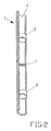
- FIG. 2 shows a diagrammatic illustration of the object to be welded in a sectional view along its longitudinal axis with two forming bodies according to the invention arranged in the object to be welded.
- FIG. 1 shows a pipe arrangement composed of four pipes 1 connected to one another.
- FIG. 1 shows a forming body 2 according to an embodiment of the invention, while it is being introduced into an inner space 6 of one of the four pipes 1 .
- the forming body 2 is produced from a dimensionally stable, compact material which has a water solubility of ⁇ 90%.
- the material of the forming body 2 preferably has as its main constituent a corn material, in particular corn starch, corn flakes and/or corn semolina.
- the forming body 2 acquires the shape with which it is introduced into the pipe 1 for the purpose of sealing the latter.
- the forming body 2 is of cylindrical design, the two edge regions 3 of the forming body 2 having a chamfer between the longitudinal side face 4 of the forming body 2 and the two end faces 5 of the forming body 2 , so that the edge regions 3 are of slanted form. It thereby becomes easier to introduce the forming body 2 into the pipe to be welded.
- the forming body 2 Before a pipe 1 is welded, the forming body 2 is introduced into the inner space 6 of the pipe 1 , so that the inner space 6 is sealed by the forming body 2 , the forming body 2 serving as a gas barrier, the intention, in particular, being to prevent the situation where argon, as the protective gas used during welding, can flow laterally out of the inner space 6 of the pipe 1 to be welded.
- a forming body 2 As shown in FIG. 2 , a forming body 2 is arranged in each case in front of and behind a location 7 to be welded. After the welding of the pipe 1 , water is introduced as a liquid into the inner space 6 of the pipe 1 , the forming body 2 dissolving in a short time, without any residue, as soon as it comes into contact with the water.
- an introduction tool 8 is used, which is designed in the shape of an elongate cylindrical plunger.
- the outer circumferential face of the introduction tool 8 is smaller than the inner circumferential face of the inner space 6 of the pipe 1 , so that the introduction tool 8 can penetrate at least partially into the inner space 6 of the pipe 1 .
- ring-shaped protuberance 9 which has a larger outer circumference or diameter than the inner circumference or inside diameter of the inner space 6 of the pipe 1 to be welded.
- the forming body is composed at least in its main constituents, but preferably completely, of corn starch, corn semolina or corn flakes or mixtures of these constituents.
- it is composed of a material which is composed solely of hydrocarbon, such that it is produced as a pure hydrocarbon body and, in particular, contains no sodium.
- the forming body is composed of a material which yields an ash content of 0.29% during incineration according to DIN 51719.
- the forming body is likewise produced from a material which, when dissolved in fully demineralized water, yields a pH value of 6.6.
- the forming body is produced from a material, in particular corn starch or a mixture of this with corn semolina and/or corn flakes, in such a way that it dissolves in a water bath or a water solution to an extent such that, when it is filtered off by means of conventional filter paper used in chemical laboratories, a residue which can be filtered off of 7.6% is formed. In this respect, therefore, water solubility amounts, in particular, to 92.4%.
Landscapes
- Engineering & Computer Science (AREA)
- Mechanical Engineering (AREA)
- Physics & Mathematics (AREA)
- Plasma & Fusion (AREA)
- Optics & Photonics (AREA)
- Arc Welding In General (AREA)
- Lining Or Joining Of Plastics Or The Like (AREA)
Applications Claiming Priority (4)
| Application Number | Priority Date | Filing Date | Title |
|---|---|---|---|
| DE102011053171A DE102011053171A1 (de) | 2011-08-31 | 2011-08-31 | Formierkörper zum Abdichten eines zu schweißenden Gegenstandes, insbesondere eines Rohres |
| DE102011053171.8 | 2011-08-31 | ||
| DE102011053171 | 2011-08-31 | ||
| PCT/EP2012/067015 WO2013030364A1 (de) | 2011-08-31 | 2012-08-31 | Formierkörper zum abdichten eines zu schweissenden gegenstandes, insbesondere eines rohres, der eine wasserlösichkeit grösser oder gleich 90 % aufweist |
Publications (2)
| Publication Number | Publication Date |
|---|---|
| US20140246482A1 US20140246482A1 (en) | 2014-09-04 |
| US9233437B2 true US9233437B2 (en) | 2016-01-12 |
Family
ID=46763094
Family Applications (1)
| Application Number | Title | Priority Date | Filing Date |
|---|---|---|---|
| US14/241,410 Expired - Fee Related US9233437B2 (en) | 2011-08-31 | 2012-08-31 | Forming body for sealing an object to be welded, more particularly a pipe |
Country Status (15)
| Country | Link |
|---|---|
| US (1) | US9233437B2 (de) |
| EP (1) | EP2750823B1 (de) |
| AU (1) | AU2012300831B2 (de) |
| CA (1) | CA2847220C (de) |
| DE (1) | DE102011053171A1 (de) |
| DK (1) | DK2750823T3 (de) |
| ES (1) | ES2640577T3 (de) |
| HR (1) | HRP20171324T1 (de) |
| HU (1) | HUE036782T2 (de) |
| LT (1) | LT2750823T (de) |
| PL (1) | PL2750823T3 (de) |
| PT (1) | PT2750823T (de) |
| SI (1) | SI2750823T1 (de) |
| WO (1) | WO2013030364A1 (de) |
| ZA (1) | ZA201402269B (de) |
Cited By (1)
| Publication number | Priority date | Publication date | Assignee | Title |
|---|---|---|---|---|
| US11054197B2 (en) | 2018-12-19 | 2021-07-06 | Unison Industries, Llc | Heat exchanger and methods of forming |
Families Citing this family (2)
| Publication number | Priority date | Publication date | Assignee | Title |
|---|---|---|---|---|
| CN113681124A (zh) * | 2021-09-13 | 2021-11-23 | 北京清大天达光电科技股份有限公司 | 一种特殊工件氩弧焊自动焊接装置及其方法 |
| CN118664028A (zh) * | 2023-06-01 | 2024-09-20 | 昆山莹帆精密五金有限公司 | 一种热管内部充氮气防氧化焊接工艺 |
Citations (27)
| Publication number | Priority date | Publication date | Assignee | Title |
|---|---|---|---|---|
| US3736400A (en) * | 1971-08-31 | 1973-05-29 | Gilbreth Co | Apparatus for damming pipe ends for welding |
| US3754115A (en) * | 1972-03-20 | 1973-08-21 | North American Rockwell | Tube sheet welding with inert gas pressure at the joint |
| US3924677A (en) * | 1974-08-29 | 1975-12-09 | Harry Koplin | Device for use in the completion of an oil or gas well |
| US4357960A (en) | 1977-03-24 | 1982-11-09 | Arthur S. Bittinger | Plumbing method and composition for use in same |
| JPS62270281A (ja) | 1986-05-20 | 1987-11-24 | Mitsubishi Heavy Ind Ltd | 管材の溶接方法 |
| JPS63101078A (ja) * | 1986-09-18 | 1988-05-06 | Mitsubishi Heavy Ind Ltd | 管材の溶接方法 |
| US5186214A (en) | 1990-06-27 | 1993-02-16 | Interprovincial Pipe Line Company | Temporary disintegratable plug for an open-ended oil pipeline |
| JPH05245633A (ja) * | 1991-03-15 | 1993-09-24 | Mitsubishi Heavy Ind Ltd | 管のシールドガス溶接方法 |
| US5318075A (en) | 1992-04-01 | 1994-06-07 | Roll Michael K | Drip stop plug |
| US5361972A (en) * | 1992-12-21 | 1994-11-08 | Barker Michael R | Purge strap for welding |
| JPH0910933A (ja) * | 1995-06-28 | 1997-01-14 | Ishikawajima Harima Heavy Ind Co Ltd | 配管溶接用の水溶紙栓 |
| US5639518A (en) * | 1994-07-11 | 1997-06-17 | Nissei Kabushiki Kaisha | Method for manufacturing biodegradable molded articles |
| US5685372A (en) | 1994-05-02 | 1997-11-11 | Halliburton Energy Services, Inc. | Temporary plug system |
| US6083456A (en) | 1992-05-13 | 2000-07-04 | Chemia, Inc. | Air freshener |
| US6251431B1 (en) | 1992-05-13 | 2001-06-26 | Chemia Corporation | Moth and insect repellant |
| JP2002205192A (ja) | 2001-01-09 | 2002-07-23 | Mitsubishi Heavy Ind Ltd | 配管の溶接方法 |
| US6619326B1 (en) | 2003-01-29 | 2003-09-16 | American Felt & Filter Company | Polyvinyl alcohol plug for plumbing applications |
| JP2003266176A (ja) * | 2002-03-15 | 2003-09-24 | Jgc Corp | 配管の溶接工法 |
| JP2004015994A (ja) | 2002-06-05 | 2004-01-15 | Toyo Denso Co Ltd | 回転電機のステータ |
| US6712097B1 (en) | 2003-03-05 | 2004-03-30 | Steve Schabel | Method and apparatus for preventing residual water formation |
| JP2004105994A (ja) | 2002-09-17 | 2004-04-08 | Hitachi Ltd | 管の溶接方法及び溶接用シールドガスの注入用ノズル |
| US20050121444A1 (en) * | 2003-12-08 | 2005-06-09 | Trochlil Thomas R. | Single ply paper product, method for manufacturing, and article |
| JP2005144533A (ja) * | 2003-11-19 | 2005-06-09 | Sanki Eng Co Ltd | 配管の溶接方法、シールドガス閉塞部材、シールドガス注入管、上昇気流遮断手段、蓋体 |
| WO2008113369A1 (de) * | 2007-03-16 | 2008-09-25 | Standardkessel Gmbh | Verfahren zur herstellung einer membranwand |
| US20090166338A1 (en) | 2006-04-11 | 2009-07-02 | Ihi Corporation | Preserving apparatus for welded joint portion and preserving method therefor |
| US8061388B1 (en) * | 2004-11-08 | 2011-11-22 | O'brien Daniel Edward | Chemical barrier plug assembly and manufacturing and dislodgement methods for hydrostatic and pneumatic testing |
| US8616432B1 (en) * | 2012-07-31 | 2013-12-31 | Michael Hacikyan | Welding purge dam for high air flow environment |
-
2011
- 2011-08-31 DE DE102011053171A patent/DE102011053171A1/de not_active Withdrawn
-
2012
- 2012-08-31 CA CA2847220A patent/CA2847220C/en not_active Expired - Fee Related
- 2012-08-31 LT LTEP12753486.5T patent/LT2750823T/lt unknown
- 2012-08-31 HR HRP20171324TT patent/HRP20171324T1/hr unknown
- 2012-08-31 PT PT127534865T patent/PT2750823T/pt unknown
- 2012-08-31 DK DK12753486.5T patent/DK2750823T3/en active
- 2012-08-31 SI SI201231065T patent/SI2750823T1/sl unknown
- 2012-08-31 PL PL12753486T patent/PL2750823T3/pl unknown
- 2012-08-31 HU HUE12753486A patent/HUE036782T2/hu unknown
- 2012-08-31 US US14/241,410 patent/US9233437B2/en not_active Expired - Fee Related
- 2012-08-31 WO PCT/EP2012/067015 patent/WO2013030364A1/de not_active Ceased
- 2012-08-31 EP EP12753486.5A patent/EP2750823B1/de not_active Not-in-force
- 2012-08-31 AU AU2012300831A patent/AU2012300831B2/en not_active Ceased
- 2012-08-31 ES ES12753486.5T patent/ES2640577T3/es active Active
-
2014
- 2014-03-27 ZA ZA2014/02269A patent/ZA201402269B/en unknown
Patent Citations (28)
| Publication number | Priority date | Publication date | Assignee | Title |
|---|---|---|---|---|
| US3736400A (en) * | 1971-08-31 | 1973-05-29 | Gilbreth Co | Apparatus for damming pipe ends for welding |
| US3754115A (en) * | 1972-03-20 | 1973-08-21 | North American Rockwell | Tube sheet welding with inert gas pressure at the joint |
| US3924677A (en) * | 1974-08-29 | 1975-12-09 | Harry Koplin | Device for use in the completion of an oil or gas well |
| US4357960A (en) | 1977-03-24 | 1982-11-09 | Arthur S. Bittinger | Plumbing method and composition for use in same |
| JPS62270281A (ja) | 1986-05-20 | 1987-11-24 | Mitsubishi Heavy Ind Ltd | 管材の溶接方法 |
| JPS63101078A (ja) * | 1986-09-18 | 1988-05-06 | Mitsubishi Heavy Ind Ltd | 管材の溶接方法 |
| US5186214A (en) | 1990-06-27 | 1993-02-16 | Interprovincial Pipe Line Company | Temporary disintegratable plug for an open-ended oil pipeline |
| JPH05245633A (ja) * | 1991-03-15 | 1993-09-24 | Mitsubishi Heavy Ind Ltd | 管のシールドガス溶接方法 |
| US5318075A (en) | 1992-04-01 | 1994-06-07 | Roll Michael K | Drip stop plug |
| US6083456A (en) | 1992-05-13 | 2000-07-04 | Chemia, Inc. | Air freshener |
| US6251431B1 (en) | 1992-05-13 | 2001-06-26 | Chemia Corporation | Moth and insect repellant |
| US5361972A (en) * | 1992-12-21 | 1994-11-08 | Barker Michael R | Purge strap for welding |
| DE69518689T2 (de) | 1994-05-02 | 2001-01-04 | Halliburton Energy Services, Inc. | Temporäres Stopfensystem für Bohrlochleitungen |
| US5685372A (en) | 1994-05-02 | 1997-11-11 | Halliburton Energy Services, Inc. | Temporary plug system |
| US5639518A (en) * | 1994-07-11 | 1997-06-17 | Nissei Kabushiki Kaisha | Method for manufacturing biodegradable molded articles |
| JPH0910933A (ja) * | 1995-06-28 | 1997-01-14 | Ishikawajima Harima Heavy Ind Co Ltd | 配管溶接用の水溶紙栓 |
| JP2002205192A (ja) | 2001-01-09 | 2002-07-23 | Mitsubishi Heavy Ind Ltd | 配管の溶接方法 |
| JP2003266176A (ja) * | 2002-03-15 | 2003-09-24 | Jgc Corp | 配管の溶接工法 |
| JP2004015994A (ja) | 2002-06-05 | 2004-01-15 | Toyo Denso Co Ltd | 回転電機のステータ |
| JP2004105994A (ja) | 2002-09-17 | 2004-04-08 | Hitachi Ltd | 管の溶接方法及び溶接用シールドガスの注入用ノズル |
| US6619326B1 (en) | 2003-01-29 | 2003-09-16 | American Felt & Filter Company | Polyvinyl alcohol plug for plumbing applications |
| US6712097B1 (en) | 2003-03-05 | 2004-03-30 | Steve Schabel | Method and apparatus for preventing residual water formation |
| JP2005144533A (ja) * | 2003-11-19 | 2005-06-09 | Sanki Eng Co Ltd | 配管の溶接方法、シールドガス閉塞部材、シールドガス注入管、上昇気流遮断手段、蓋体 |
| US20050121444A1 (en) * | 2003-12-08 | 2005-06-09 | Trochlil Thomas R. | Single ply paper product, method for manufacturing, and article |
| US8061388B1 (en) * | 2004-11-08 | 2011-11-22 | O'brien Daniel Edward | Chemical barrier plug assembly and manufacturing and dislodgement methods for hydrostatic and pneumatic testing |
| US20090166338A1 (en) | 2006-04-11 | 2009-07-02 | Ihi Corporation | Preserving apparatus for welded joint portion and preserving method therefor |
| WO2008113369A1 (de) * | 2007-03-16 | 2008-09-25 | Standardkessel Gmbh | Verfahren zur herstellung einer membranwand |
| US8616432B1 (en) * | 2012-07-31 | 2013-12-31 | Michael Hacikyan | Welding purge dam for high air flow environment |
Non-Patent Citations (3)
| Title |
|---|
| International Preliminary Report on Patentability mailed Feb. 28, 2014, for International Application No. PCT/EP2012/067015 filed Aug. 31, 2012. |
| International Search Report mailed Dec. 4, 2012, for International Application No. PCT/EP2012/067015 filed Aug. 31, 2012. |
| Office Action in German Patent Application No. 10 2011 053 171.8 dated Mar. 8, 2012. |
Cited By (1)
| Publication number | Priority date | Publication date | Assignee | Title |
|---|---|---|---|---|
| US11054197B2 (en) | 2018-12-19 | 2021-07-06 | Unison Industries, Llc | Heat exchanger and methods of forming |
Also Published As
| Publication number | Publication date |
|---|---|
| ZA201402269B (en) | 2015-08-26 |
| LT2750823T (lt) | 2017-09-25 |
| AU2012300831B2 (en) | 2015-09-03 |
| PL2750823T3 (pl) | 2017-11-30 |
| US20140246482A1 (en) | 2014-09-04 |
| PT2750823T (pt) | 2017-10-02 |
| HUE036782T2 (hu) | 2018-07-30 |
| AU2012300831A1 (en) | 2014-04-03 |
| HRP20171324T1 (hr) | 2017-11-03 |
| ES2640577T3 (es) | 2017-11-03 |
| DE102011053171A1 (de) | 2013-02-28 |
| EP2750823A1 (de) | 2014-07-09 |
| CA2847220A1 (en) | 2013-03-07 |
| EP2750823B1 (de) | 2017-07-12 |
| WO2013030364A1 (de) | 2013-03-07 |
| CA2847220C (en) | 2017-09-19 |
| DK2750823T3 (en) | 2017-10-09 |
| SI2750823T1 (sl) | 2017-11-30 |
Similar Documents
| Publication | Publication Date | Title |
|---|---|---|
| CA2847220C (en) | Forming body for sealing an object to be welded, more particularly a pipe, having a water solubility greater than or equal to 90% | |
| AU2014205246A1 (en) | Fitting for joining tubes and method of joining tubes | |
| CN104405975A (zh) | 具有承插口的钢管 | |
| CN104019288B (zh) | 一种双金属复合管及其制造工艺 | |
| CN105108297A (zh) | 一种整体复合法兰及其制造方法 | |
| JP2020025925A (ja) | 廃棄物処分場の埋め立て方法 | |
| CN203176578U (zh) | 密封式双卡套管接头 | |
| SA519410165B1 (ar) | نظام قفل إيجابي للتوصيلات المقيدة لأنابيب وتركيبات من الحديد اللدن المغزول | |
| CN204984280U (zh) | 一种新型密封钻杆 | |
| CN104154375A (zh) | 高压管道的测温测压数据采集头 | |
| CN203298885U (zh) | 一种测温测压数据采集头 | |
| CN103133785A (zh) | 管道穿墙部位的防水处理结构 | |
| RU180307U1 (ru) | Фитинговое соединение для металлопластиковых труб | |
| CN204893199U (zh) | 一种整体复合法兰 | |
| KR200481756Y1 (ko) | 불량률을 낮춘 분지 파이프 어셈블리 | |
| CN200992812Y (zh) | 一种化学灌浆用孔口灌浆止浆塞 | |
| CN215807142U (zh) | 一种管口的内压自紧密封结构 | |
| CN105436812A (zh) | 一种零件过钉孔渗漏的修复方法 | |
| CN203214932U (zh) | 不锈钢球阀 | |
| CN203099185U (zh) | 集成管道 | |
| CN203036147U (zh) | 饮用水净化器管道式快速接头 | |
| CN203880262U (zh) | 一种输送管及泵送设备 | |
| CN202691346U (zh) | 一种超高压试验压力钢管装置 | |
| CN106885077A (zh) | 一种采用柔性石墨密封圈静态密封的管道连接装置 | |
| CN204300554U (zh) | 一种耐高温高压的扩口式锥密封螺纹管接头 |
Legal Events
| Date | Code | Title | Description |
|---|---|---|---|
| AS | Assignment |
Owner name: MITSUBISHI HITACHI POWER SYSTEMS EUROPE GMBH, GERM Free format text: ASSIGNMENT OF ASSIGNORS INTEREST;ASSIGNOR:BUSCHMANN, MICHAEL;REEL/FRAME:032860/0163 Effective date: 20140306 |
|
| STCF | Information on status: patent grant |
Free format text: PATENTED CASE |
|
| FEPP | Fee payment procedure |
Free format text: MAINTENANCE FEE REMINDER MAILED (ORIGINAL EVENT CODE: REM.); ENTITY STATUS OF PATENT OWNER: LARGE ENTITY |
|
| LAPS | Lapse for failure to pay maintenance fees |
Free format text: PATENT EXPIRED FOR FAILURE TO PAY MAINTENANCE FEES (ORIGINAL EVENT CODE: EXP.); ENTITY STATUS OF PATENT OWNER: LARGE ENTITY |
|
| STCH | Information on status: patent discontinuation |
Free format text: PATENT EXPIRED DUE TO NONPAYMENT OF MAINTENANCE FEES UNDER 37 CFR 1.362 |
|
| FP | Lapsed due to failure to pay maintenance fee |
Effective date: 20200112 |