US9216121B2 - Support and containment structure for persons - Google Patents
Support and containment structure for persons Download PDFInfo
- Publication number
- US9216121B2 US9216121B2 US13/393,128 US201013393128A US9216121B2 US 9216121 B2 US9216121 B2 US 9216121B2 US 201013393128 A US201013393128 A US 201013393128A US 9216121 B2 US9216121 B2 US 9216121B2
- Authority
- US
- United States
- Prior art keywords
- support
- containment
- persons
- support member
- modular
- Prior art date
- Legal status (The legal status is an assumption and is not a legal conclusion. Google has not performed a legal analysis and makes no representation as to the accuracy of the status listed.)
- Active, expires
Links
- 238000004873 anchoring Methods 0.000 claims description 3
- 230000013011 mating Effects 0.000 claims 1
- 230000000694 effects Effects 0.000 description 4
- 230000003203 everyday effect Effects 0.000 description 2
- 230000007170 pathology Effects 0.000 description 2
- 208000007101 Muscle Cramp Diseases 0.000 description 1
- 208000005392 Spasm Diseases 0.000 description 1
- 230000009471 action Effects 0.000 description 1
- 238000007792 addition Methods 0.000 description 1
- 230000002354 daily effect Effects 0.000 description 1
- 230000007547 defect Effects 0.000 description 1
- 230000001419 dependent effect Effects 0.000 description 1
- 230000004048 modification Effects 0.000 description 1
- 238000012986 modification Methods 0.000 description 1
- 230000001575 pathological effect Effects 0.000 description 1
- 210000004197 pelvis Anatomy 0.000 description 1
- 230000001144 postural effect Effects 0.000 description 1
Images


Classifications
-
- A—HUMAN NECESSITIES
- A61—MEDICAL OR VETERINARY SCIENCE; HYGIENE
- A61G—TRANSPORT, PERSONAL CONVEYANCES, OR ACCOMMODATION SPECIALLY ADAPTED FOR PATIENTS OR DISABLED PERSONS; OPERATING TABLES OR CHAIRS; CHAIRS FOR DENTISTRY; FUNERAL DEVICES
- A61G5/00—Chairs or personal conveyances specially adapted for patients or disabled persons, e.g. wheelchairs
- A61G5/10—Parts, details or accessories
- A61G5/12—Rests specially adapted therefor, e.g. for the head or the feet
-
- A—HUMAN NECESSITIES
- A61—MEDICAL OR VETERINARY SCIENCE; HYGIENE
- A61F—FILTERS IMPLANTABLE INTO BLOOD VESSELS; PROSTHESES; DEVICES PROVIDING PATENCY TO, OR PREVENTING COLLAPSING OF, TUBULAR STRUCTURES OF THE BODY, e.g. STENTS; ORTHOPAEDIC, NURSING OR CONTRACEPTIVE DEVICES; FOMENTATION; TREATMENT OR PROTECTION OF EYES OR EARS; BANDAGES, DRESSINGS OR ABSORBENT PADS; FIRST-AID KITS
- A61F5/00—Orthopaedic methods or devices for non-surgical treatment of bones or joints; Nursing devices; Anti-rape devices
- A61F5/01—Orthopaedic devices, e.g. splints, casts or braces
- A61F5/02—Orthopaedic corsets
- A61F5/022—Orthopaedic corsets consisting of one or more shells
-
- A—HUMAN NECESSITIES
- A61—MEDICAL OR VETERINARY SCIENCE; HYGIENE
- A61G—TRANSPORT, PERSONAL CONVEYANCES, OR ACCOMMODATION SPECIALLY ADAPTED FOR PATIENTS OR DISABLED PERSONS; OPERATING TABLES OR CHAIRS; CHAIRS FOR DENTISTRY; FUNERAL DEVICES
- A61G5/00—Chairs or personal conveyances specially adapted for patients or disabled persons, e.g. wheelchairs
- A61G5/10—Parts, details or accessories
- A61G5/12—Rests specially adapted therefor, e.g. for the head or the feet
- A61G5/122—Rests specially adapted therefor, e.g. for the head or the feet for the back
-
- A61G2005/122—
-
- A—HUMAN NECESSITIES
- A61—MEDICAL OR VETERINARY SCIENCE; HYGIENE
- A61G—TRANSPORT, PERSONAL CONVEYANCES, OR ACCOMMODATION SPECIALLY ADAPTED FOR PATIENTS OR DISABLED PERSONS; OPERATING TABLES OR CHAIRS; CHAIRS FOR DENTISTRY; FUNERAL DEVICES
- A61G2210/00—Devices for specific treatment or diagnosis
- A61G2210/10—Devices for specific treatment or diagnosis for orthopedics
Definitions
- the present invention concerns a support and containment structure for persons who cannot maintain an adequate and functional position of the body, such as for example the disabled.
- the present invention is preferably applied where a person with motor difficulties needs support, such as for example a backrest, a corset or other for his/her trunk, which is able to accompany him/her in carrying out his/her daily activities with an adequate level of flexibility
- Disabled people have different support requirements according to the type of pathology by which they are affected, and to the defects in posture that need to be compensated.
- Such structures are generally padded and lined with spongy material or other, so as to make them more comfortable; additional accessories can be applied so as to improve the postural functionality, depending on the requirements and type of user.
- the disabled person In the first case the disabled person would need a structure able to guarantee great flexibility, in the second case he/she would need a more rigid structure.
- a support and containment structure comprising a support member with a mainly longitudinal development in a single piece, able to support the spine of the disabled person during his/her movements.
- This solution has the disadvantage that it cannot easily be personalized and adapted to the individual characteristics and needs of the person for whom it is intended.
- Purpose of the present invention is to achieve a support and containment structure for disabled persons which can be personalized and is able to adapt to every type of requirement of the users and their movements, by means of a flexible structure which allows a precise but not fixed adjustment, able to follow the little movements of the persons, assisting them and providing, where necessary, a moderate control. It is therefore the disabled person who determines the position of the various modules of the support and containment structure and the level of rigidity of the structure.
- the Applicant has devised, tested and embodied the present invention to overcome the shortcomings of the state of the art and to obtain these and other purposes and advantages.
- a support and containment structure for persons comprises at least a support member, which extends mainly along a longitudinal axis, and at least a containment element, advantageously a plurality of containment elements.
- the at least one containment element is mounted transverse on the at least one support member in order to contain the trunk of the person in a personalized manner.
- the at least one support member consists of a plurality of modular elements selectively adjustable in height and clampable in a stable position by means of relative clamping means.
- the modular elements assume, all together and in use, a position substantially adapted to the trunk of the disabled person in correspondence with the user's spine.
- the support member together with the modular elements attached thereto, constitute the bearing column of the support and containment structure, whereas the transverse containment elements constitute the personalized rib structure according to the applications required on each occasion for the patient and/or the specific user.
- each modular element is provided with a female part and/or a male part.
- the female part of each modular element cooperates, at least partly, with the male part of the adjacent modular element and vice versa, so as to constitute the support member.
- each modular element has at least laterally shaped positioning seatings for the positioning and relative anchoring of at least part of the relative transverse containment elements.
- the transverse containment elements have a plurality of holes and/or eyelets to allow the positioning thereof, and then attachment, in a variable position with respect to the longitudinal support member.
- the clamping means comprise at least a clamping lever or plate and at least a stopping nut to selectively clamp the modular elements in the adjusted position and at least an attachment element to prevent the at least one stopping nut from accidentally coming loose due to vibrations or other.
- attachment elements which are disposed respectively between the containment elements and the support member to which the containment elements are attached, and between the support member and the clamping levers or plates, so as to allow a stable attachment of the modular elements to each other.
- the two attachment elements which can each be made in a single piece or may in turn consist of a plurality of fixed elements to constitute a single piece, have a plurality of shaped holes and/or eyelets, one for each modular element.
- Each modular element of the support member is able to be disposed in a clamping position that can vary along the hole or eyelet associated therewith.
- a close-up position of the modular elements causes a stiffening of the support member, whereas a distanced position makes the support member more flexible.
- each containment element is mounted laterally on the support member by jointing.
- each containment element is mounted on the support member by means of a hinging element.
- the support and containment structure comprises stiffening rings, attached transverse to at least two adjacent modular elements, able to confer greater rigidity to the structure.
- the support and containment structure comprises hooks to assemble the structure on seating or movement means for the disabled.
- the support and containment structure comprises at least an additional lateral support, applicable to one end of the at least one containment element in order to extend it and allow it to surround the disabled person's body more
- FIG. 1 is a front view of a support and containment structure, showing the surface that houses the trunk of the disabled person;
- FIG. 2 is a lateral view of the support and containment structure for disabled persons in FIG. 1 ;
- FIG. 3 is a rear view of the support and containment structure for disabled persons in FIG. 1 , showing the surface of the structure that rests on carriages, wheelchairs or other;
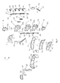
- FIG. 4 is an exploded view of the support and containment structure for disabled persons in FIG. 1 ;
- FIG. 5 is a front view of another form of embodiment of the present invention.
- FIGS. 6 and 7 show respectively sections A-A and B-B of FIG. 5 ;
- FIG. 8 is an exploded view of the embodiment in FIG. 5 .
- a support and containment structure 10 for disabled persons comprises a support member 23 , which extends mainly along a longitudinal axis Y, and a plurality of containment elements 11 , disposed transverse to the support member 23 and mounted upon it, each able to contain, at least partly, specific parts of the trunk of the disabled person.
- the support and containment structure 10 has a front surface, in use, shown in FIG. 1 , to house the trunk of the disabled person and a rear surface, in use, shown in FIG. 3 , to rest or attach the structure to walking means, transport means or other, such as for example carriages, wheelchairs, Zimmer frames etc.
- the containment elements 11 have different shapes and sizes, according to the position occupied along the support member 23 and according to the part of the disabled person's trunk to be supported or contained.
- the containment elements 11 are also at least partly bent forward (in the direction indication by the arrow F in FIG. 2 ) with respect to the support member 23 so as to accommodate ergonomically a corresponding portion of the disabled person's trunk.
- an additional lateral support 20 is mounted, as shown in FIGS. 1 and 2 , to provide a greater support to the disabled person's trunk.
- an attachment element 21 is attached to the additional lateral support 20 and cooperates with an attachment element 22 , located on the bent end of the element 11 to which the support 20 is applied.
- each containment element 11 at the front part of the support and containment structure 10 , has a plurality of Velcro surfaces 12 to allow to cover the structure 10 with padding (indicated by the reference number 30 only in the form of embodiment shown in FIG. 8 ) able to make it comfortable.
- the support member 23 on which the containment elements 11 are mounted, is able to support the disabled person's spine, adapting to its curves.
- the support member 23 consists of a plurality of modular elements 19 , disposed adjacent to each other and substantially aligned in the direction of the axis Y, and assumes, in use, an overall position adapted to the person's trunk in correspondence with his/her spine.
- each modular element 19 is equipped with a female part and/or a male part.
- each modular element 19 cooperates, at least partly, with the male part of the adjacent modular element 19 and vice versa, to form the support member 23 .
- the reciprocal positioning of the modular elements 19 is adjustable according to the desired level of rigidity/flexibility of the support member 23 , inasmuch as the closer the modular elements 19 are disposed to each other and overlapping, the more the rigidity of the support member 23 increases.
- the support and containment structure 10 for the disabled also comprises two attachment elements, respectively front 13 and rear 27 , with a mainly longitudinal development, and a plurality of stopping nuts 25 and clamping levers 14 , as shown in FIGS. 2 and 4 .
- the attachment elements 13 and 27 are provided with eyelets, respectively 26 and 28 , disposed one after the other along the longitudinal direction.
- the attachment element 13 is positioned between the support member 23 and the containment elements 11 , whereas the attachment element 27 is disposed to the rear of the attachment element 13 , between the support member 23 and the clamping levers 14 .
- each modular element 19 of the support member 23 a containment element 11 is mounted and the attachment element 13 is interposed between them, in correspondence with an eyelet 26 .
- the attachment element 27 is positioned to the rear of the support member 23 and each eyelet 28 is located in correspondence with one of the modular elements 19 .
- Each clamping lever 14 has a threaded element 29 which passes through the eyelets 28 and 26 and through suitable holes made iii the modular elements 19 and the containment elements 11 associated therewith.
- the threaded element 29 cooperates with the stopping nut 25 associated with it, so as to clamp the corresponding modular element 19 in the desired position.
- the attachment elements 13 and 27 clamped between the stopping nuts 25 and the clamping levers 14 , prevent the nuts 25 from accidentally coming loose due to the action of vibrations.
- the deliberate loosening of the nuts 25 allows to make the modular elements 19 slide inside the eyelets 26 and 28 of the corresponding attachment elements 13 and 27 , to allow to vary the position of the modular elements 19 with respect to each other according to the specific requirements of the disabled person.
- each stopping nut 25 can be temporarily clamped with respect to the eyelets 26 and 28 , so as to temporarily determine a reciprocal stable position of the modular elements 19 with respect to each other.
- two hooks 15 are attached transverse to a pair of modular elements 19 so as to allow to assemble the structure 10 on seating and movement means for the disabled, such as for example carriages, wheelchairs, Zimmer frames or other.
- the hooks 15 are attached to the pair of modular elements 19 by means of two arms 17 , each longitudinally passed through by at least an eyelet 18 , which also perform the function of stiffening the structure 10 .
- FIGS. 5-8 another form of embodiment of the structure according to the present invention is shown.
- the same numbers are used to refer to identical or equivalent parts as those already described with reference to FIGS. 1-4 and will not be described further.
- the front 13 and rear 27 attachment elements are not made in a single piece as in the previous embodiment, but consist of a plurality of flat elements 31 , attached to each other. In this way, according to the reciprocal positioning of the flat elements 31 , and the number thereof, the support member 23 can be personalized to be adapted to the specific case and patient or user.
- the flat elements can therefore have holes 32 which, at the moment of assembly, are positioned overlapping each other, and aligned with corresponding holes 33 present on the modular elements 19 , and aligned with corresponding holes 34 present on the transverse containment elements 11 .
- Respective front nuts 25 and rear bolts 125 are inserted through the holes 32 , 33 and 34 , to allow the reciprocal attachment of all the elements, to constitute the structure 10 .
- Each modular element 19 at its lateral ends, has shaped positioning seatings 38 for the positioning and relative anchoring of at least part of the corresponding lateral end of the relative transverse containment elements 11 .
- a plate 35 equipped with attachment teeth 36 , is coupled with each modular element 19 , cooperating with respective grooves 37 , to hide from view the attachment elements of the structure 10 .
Landscapes
- Health & Medical Sciences (AREA)
- Life Sciences & Earth Sciences (AREA)
- Veterinary Medicine (AREA)
- Public Health (AREA)
- General Health & Medical Sciences (AREA)
- Animal Behavior & Ethology (AREA)
- Biomedical Technology (AREA)
- Vascular Medicine (AREA)
- Heart & Thoracic Surgery (AREA)
- Engineering & Computer Science (AREA)
- Orthopedic Medicine & Surgery (AREA)
- Nursing (AREA)
- Orthopedics, Nursing, And Contraception (AREA)
- Invalid Beds And Related Equipment (AREA)
- Chair Legs, Seat Parts, And Backrests (AREA)
- Helmets And Other Head Coverings (AREA)
- Clamps And Clips (AREA)
Applications Claiming Priority (4)
| Application Number | Priority Date | Filing Date | Title |
|---|---|---|---|
| ITUD2009A000145 | 2009-08-31 | ||
| ITUD2009A0145 | 2009-08-31 | ||
| ITUD2009A000145A IT1395424B1 (it) | 2009-08-31 | 2009-08-31 | Struttura di supporto e contenimento per persone |
| PCT/IB2010/002099 WO2011024061A1 (en) | 2009-08-31 | 2010-08-27 | Support and containment structure for persons |
Publications (2)
| Publication Number | Publication Date |
|---|---|
| US20120157901A1 US20120157901A1 (en) | 2012-06-21 |
| US9216121B2 true US9216121B2 (en) | 2015-12-22 |
Family
ID=42081416
Family Applications (1)
| Application Number | Title | Priority Date | Filing Date |
|---|---|---|---|
| US13/393,128 Active 2030-10-08 US9216121B2 (en) | 2009-08-31 | 2010-08-27 | Support and containment structure for persons |
Country Status (20)
| Country | Link |
|---|---|
| US (1) | US9216121B2 (pt) |
| EP (1) | EP2473148B1 (pt) |
| JP (1) | JP5632477B2 (pt) |
| CN (1) | CN102497845B (pt) |
| AU (1) | AU2010288229B2 (pt) |
| BR (1) | BR112012004526B1 (pt) |
| CA (1) | CA2772101C (pt) |
| DK (1) | DK2473148T3 (pt) |
| ES (1) | ES2431015T3 (pt) |
| HK (1) | HK1171938A1 (pt) |
| IL (1) | IL218341A (pt) |
| IT (1) | IT1395424B1 (pt) |
| MX (1) | MX2012002330A (pt) |
| NZ (1) | NZ598894A (pt) |
| PL (1) | PL2473148T3 (pt) |
| RU (1) | RU2538529C2 (pt) |
| SG (1) | SG178892A1 (pt) |
| SI (1) | SI2473148T1 (pt) |
| WO (1) | WO2011024061A1 (pt) |
| ZA (1) | ZA201202270B (pt) |
Cited By (5)
| Publication number | Priority date | Publication date | Assignee | Title |
|---|---|---|---|---|
| US11006758B1 (en) * | 2020-01-15 | 2021-05-18 | Merits Health Products Co., Ltd. | Chairback support structure |
| US11123214B2 (en) * | 2017-09-11 | 2021-09-21 | Peter Wilson | Back-brace assistive device |
| US11389350B2 (en) * | 2020-09-29 | 2022-07-19 | Permobil, Inc. | Adjustable back support |
| US20230018799A1 (en) * | 2021-07-16 | 2023-01-19 | Joon Hyeok Choi | Upper garment with customized spine support device |
| US11877945B2 (en) | 2016-01-11 | 2024-01-23 | Ryan C. Murdock | External spinal brace |
Families Citing this family (9)
| Publication number | Priority date | Publication date | Assignee | Title |
|---|---|---|---|---|
| DE102011117672B4 (de) | 2011-09-19 | 2013-07-11 | Otto Bock Mobility Solutions Gmbh | Rückenlehne |
| FR3005848B1 (fr) * | 2013-05-23 | 2021-01-15 | Evom | Dispositif modulaire de protection dorsale articulee |
| CN106163461B (zh) | 2014-01-17 | 2019-08-06 | 绿太阳控股有限责任公司 | 用于畸形矫正的矫形器 |
| GB2526785A (en) * | 2014-05-23 | 2015-12-09 | Specmat Ltd | Adjustable backrest for a chair |
| EP3585323B1 (en) * | 2017-03-03 | 2023-09-27 | Polyspine Holdings Pty Ltd | A modular supportive spinal brace |
| US11540934B2 (en) * | 2017-04-28 | 2023-01-03 | Brandeis University | Adjustable back brace and methods for use thereof |
| US11980562B2 (en) * | 2017-12-14 | 2024-05-14 | Green Sun Medical, LLC | Reconfigurable orthosis for deformity correction |
| AU2018100610A4 (en) * | 2018-05-11 | 2018-06-14 | Whaeatoa Pty Ltd | A support garment |
| CN112842658B (zh) * | 2021-02-19 | 2022-08-02 | 吉林大学第一医院 | 一种用于脊柱外科的矫正装置 |
Citations (6)
| Publication number | Priority date | Publication date | Assignee | Title |
|---|---|---|---|---|
| US5840051A (en) * | 1995-08-24 | 1998-11-24 | Towsley; Harold E. | Flexible back, neck and shoulder brace |
| US6257664B1 (en) | 1998-11-16 | 2001-07-10 | Invacare Corporation | Multiple adjustable back assembly for use with wheelchair |
| WO2002022067A1 (en) | 2000-09-18 | 2002-03-21 | Itop S.R.L. | Dynamic articulated orthopaedic seat-back |
| WO2003051264A1 (en) | 2001-12-14 | 2003-06-26 | The Helping Hand Company (Ledbury) Limited | Improvements relating to torso support structures |
| US20080021357A1 (en) * | 2004-04-29 | 2008-01-24 | Igal Firsov | Orthotic Bracing Device |
| EP2070501A2 (en) | 2007-12-06 | 2009-06-17 | The helping hand company (Ledbury) limited | Seating support |
Family Cites Families (4)
| Publication number | Priority date | Publication date | Assignee | Title |
|---|---|---|---|---|
| SE454944B (sv) * | 1985-11-25 | 1988-06-13 | Camp Scandinavia Ab | Anordning och forfarande for utprovning av ryggortos eller korsett |
| JP2005349177A (ja) * | 2004-05-14 | 2005-12-22 | Yukio Nakayama | 椎骨伸張装置 |
| KR100916753B1 (ko) * | 2007-07-31 | 2009-09-14 | 윤경호 | 의자 등받이용 메모리 장치 |
| JP5015118B2 (ja) * | 2007-11-16 | 2012-08-29 | 東允 宣 | 角度調節部を備えた脊椎側湾症補助器 |
-
2009
- 2009-08-31 IT ITUD2009A000145A patent/IT1395424B1/it active
-
2010
- 2010-08-27 PL PL10763423T patent/PL2473148T3/pl unknown
- 2010-08-27 SG SG2012013579A patent/SG178892A1/en unknown
- 2010-08-27 ES ES10763423T patent/ES2431015T3/es active Active
- 2010-08-27 DK DK10763423.0T patent/DK2473148T3/da active
- 2010-08-27 CN CN201080042574.5A patent/CN102497845B/zh not_active Expired - Fee Related
- 2010-08-27 BR BR112012004526-1A patent/BR112012004526B1/pt not_active IP Right Cessation
- 2010-08-27 SI SI201030363T patent/SI2473148T1/sl unknown
- 2010-08-27 MX MX2012002330A patent/MX2012002330A/es active IP Right Grant
- 2010-08-27 NZ NZ598894A patent/NZ598894A/xx not_active IP Right Cessation
- 2010-08-27 US US13/393,128 patent/US9216121B2/en active Active
- 2010-08-27 JP JP2012526138A patent/JP5632477B2/ja active Active
- 2010-08-27 AU AU2010288229A patent/AU2010288229B2/en not_active Ceased
- 2010-08-27 WO PCT/IB2010/002099 patent/WO2011024061A1/en active Application Filing
- 2010-08-27 CA CA2772101A patent/CA2772101C/en active Active
- 2010-08-27 RU RU2012110879/12A patent/RU2538529C2/ru active
- 2010-08-27 EP EP10763423.0A patent/EP2473148B1/en active Active
-
2012
- 2012-02-27 IL IL218341A patent/IL218341A/en active IP Right Grant
- 2012-03-28 ZA ZA2012/02270A patent/ZA201202270B/en unknown
- 2012-12-12 HK HK12112840.3A patent/HK1171938A1/zh not_active IP Right Cessation
Patent Citations (6)
| Publication number | Priority date | Publication date | Assignee | Title |
|---|---|---|---|---|
| US5840051A (en) * | 1995-08-24 | 1998-11-24 | Towsley; Harold E. | Flexible back, neck and shoulder brace |
| US6257664B1 (en) | 1998-11-16 | 2001-07-10 | Invacare Corporation | Multiple adjustable back assembly for use with wheelchair |
| WO2002022067A1 (en) | 2000-09-18 | 2002-03-21 | Itop S.R.L. | Dynamic articulated orthopaedic seat-back |
| WO2003051264A1 (en) | 2001-12-14 | 2003-06-26 | The Helping Hand Company (Ledbury) Limited | Improvements relating to torso support structures |
| US20080021357A1 (en) * | 2004-04-29 | 2008-01-24 | Igal Firsov | Orthotic Bracing Device |
| EP2070501A2 (en) | 2007-12-06 | 2009-06-17 | The helping hand company (Ledbury) limited | Seating support |
Non-Patent Citations (2)
| Title |
|---|
| Chinese Office Action from Counterpart Chinese Application No. 20108042574.5 dated Mar. 4, 2014 (7 pages). |
| International Search Report & Written Opinion for PCT/IB2010/002099. |
Cited By (6)
| Publication number | Priority date | Publication date | Assignee | Title |
|---|---|---|---|---|
| US11877945B2 (en) | 2016-01-11 | 2024-01-23 | Ryan C. Murdock | External spinal brace |
| US11123214B2 (en) * | 2017-09-11 | 2021-09-21 | Peter Wilson | Back-brace assistive device |
| US11006758B1 (en) * | 2020-01-15 | 2021-05-18 | Merits Health Products Co., Ltd. | Chairback support structure |
| US11389350B2 (en) * | 2020-09-29 | 2022-07-19 | Permobil, Inc. | Adjustable back support |
| US20230018799A1 (en) * | 2021-07-16 | 2023-01-19 | Joon Hyeok Choi | Upper garment with customized spine support device |
| US11596188B2 (en) * | 2021-07-16 | 2023-03-07 | Joon Hyeok Choi | Upper garment with customized spine support device |
Also Published As
| Publication number | Publication date |
|---|---|
| AU2010288229B2 (en) | 2015-01-22 |
| AU2010288229A1 (en) | 2012-04-12 |
| RU2012110879A (ru) | 2013-10-10 |
| CN102497845A (zh) | 2012-06-13 |
| HK1171938A1 (zh) | 2013-04-12 |
| ES2431015T3 (es) | 2013-11-22 |
| SG178892A1 (en) | 2012-04-27 |
| CA2772101A1 (en) | 2011-03-03 |
| ZA201202270B (en) | 2012-12-27 |
| BR112012004526B1 (pt) | 2020-05-12 |
| EP2473148B1 (en) | 2013-07-24 |
| CN102497845B (zh) | 2015-09-09 |
| PL2473148T3 (pl) | 2013-12-31 |
| WO2011024061A1 (en) | 2011-03-03 |
| US20120157901A1 (en) | 2012-06-21 |
| RU2538529C2 (ru) | 2015-01-10 |
| IL218341A0 (en) | 2012-04-30 |
| JP5632477B2 (ja) | 2014-11-26 |
| IT1395424B1 (it) | 2012-09-14 |
| DK2473148T3 (da) | 2013-10-14 |
| ITUD20090145A1 (it) | 2011-03-01 |
| MX2012002330A (es) | 2012-06-19 |
| CA2772101C (en) | 2017-11-28 |
| IL218341A (en) | 2014-01-30 |
| JP2013502963A (ja) | 2013-01-31 |
| NZ598894A (en) | 2012-12-21 |
| SI2473148T1 (sl) | 2013-11-29 |
| EP2473148A1 (en) | 2012-07-11 |
| WO2011024061A8 (en) | 2011-04-28 |
| BR112012004526A2 (pt) | 2017-05-30 |
Similar Documents
| Publication | Publication Date | Title |
|---|---|---|
| US9216121B2 (en) | Support and containment structure for persons | |
| RU2562038C2 (ru) | Постуральная система | |
| US10314750B2 (en) | Sliding arm mechanism for wheelchairs | |
| US6186594B1 (en) | Flexible contour wheelchair backrest | |
| US20080067850A1 (en) | Backrest for a chair | |
| CA2785513A1 (en) | Backrest for wheelchair | |
| US20110105972A1 (en) | Belt for posture correction | |
| US20160200382A1 (en) | Ergonomic seat for a cycle | |
| US9687078B2 (en) | Portable therapeutic seat device | |
| US20080251681A1 (en) | Mounting Assembly For Stable Attachment of a Seat, Particularly a Bicycle Saddle | |
| US20050023872A1 (en) | Modular seat cushion with interlocking human support and base portions and method of creating and using a seat cushion | |
| KR101481811B1 (ko) | 의자 보조기구 | |
| JP3223462U (ja) | 着座補助器具 | |
| CA3178061A1 (en) | Scoliosis brace | |
| KR19990046590A (ko) | 의자등받이 | |
| EP0152716A1 (fr) | Siège pour handicapés | |
| KR20120003466U (ko) | 자세 교정용 벨트가 부착된 의자 | |
| US20110193376A1 (en) | Auxiliary Support for Bicycle Saddle | |
| US20240074932A1 (en) | Buttock support for at least partial load-relief of the body weight of a person, and load-relief system comprising such a buttock support | |
| KR101161288B1 (ko) | 의자용 등받이 | |
| KR200423526Y1 (ko) | 장애인용 휠체어 | |
| KR200207201Y1 (ko) | 접철식 명상용 방석 | |
| JP6854583B2 (ja) | 着座補助具 | |
| KR20210149429A (ko) | 농업용 의자 | |
| EP1354538A1 (en) | Backrest for a chair, in particluar for a wheelchair |
Legal Events
| Date | Code | Title | Description |
|---|---|---|---|
| STCF | Information on status: patent grant |
Free format text: PATENTED CASE |
|
| MAFP | Maintenance fee payment |
Free format text: PAYMENT OF MAINTENANCE FEE, 4TH YR, SMALL ENTITY (ORIGINAL EVENT CODE: M2551); ENTITY STATUS OF PATENT OWNER: SMALL ENTITY Year of fee payment: 4 |
|
| MAFP | Maintenance fee payment |
Free format text: PAYMENT OF MAINTENANCE FEE, 8TH YR, SMALL ENTITY (ORIGINAL EVENT CODE: M2552); ENTITY STATUS OF PATENT OWNER: SMALL ENTITY Year of fee payment: 8 |