US9080112B2 - Filtration method for refining and chemical industries - Google Patents
Filtration method for refining and chemical industries Download PDFInfo
- Publication number
- US9080112B2 US9080112B2 US13/470,340 US201213470340A US9080112B2 US 9080112 B2 US9080112 B2 US 9080112B2 US 201213470340 A US201213470340 A US 201213470340A US 9080112 B2 US9080112 B2 US 9080112B2
- Authority
- US
- United States
- Prior art keywords
- housings
- compartment
- process stream
- contaminants
- stream
- Prior art date
- Legal status (The legal status is an assumption and is not a legal conclusion. Google has not performed a legal analysis and makes no representation as to the accuracy of the status listed.)
- Active - Reinstated, expires
Links
- 238000001914 filtration Methods 0.000 title claims description 80
- 239000000126 substance Substances 0.000 title description 7
- 238000007670 refining Methods 0.000 title description 5
- 238000000034 method Methods 0.000 claims abstract description 100
- 239000000356 contaminant Substances 0.000 claims abstract description 51
- 239000010802 sludge Substances 0.000 claims abstract description 21
- 230000005298 paramagnetic effect Effects 0.000 claims abstract description 11
- 238000005192 partition Methods 0.000 claims description 5
- 239000011280 coal tar Substances 0.000 claims description 3
- 239000000571 coke Substances 0.000 claims description 3
- 238000006317 isomerization reaction Methods 0.000 claims description 3
- 239000003350 kerosene Substances 0.000 claims description 3
- 238000011010 flushing procedure Methods 0.000 claims 2
- 230000005291 magnetic effect Effects 0.000 abstract description 32
- XEEYBQQBJWHFJM-UHFFFAOYSA-N Iron Chemical compound [Fe] XEEYBQQBJWHFJM-UHFFFAOYSA-N 0.000 abstract description 30
- 239000010935 stainless steel Substances 0.000 abstract description 22
- 229910001220 stainless steel Inorganic materials 0.000 abstract description 22
- JEIPFZHSYJVQDO-UHFFFAOYSA-N iron(III) oxide Inorganic materials O=[Fe]O[Fe]=O JEIPFZHSYJVQDO-UHFFFAOYSA-N 0.000 abstract description 15
- 229910052742 iron Inorganic materials 0.000 abstract description 14
- 238000001311 chemical methods and process Methods 0.000 abstract description 5
- 231100001261 hazardous Toxicity 0.000 abstract description 5
- 238000010276 construction Methods 0.000 abstract description 3
- 238000012423 maintenance Methods 0.000 abstract description 2
- 238000005260 corrosion Methods 0.000 description 20
- 230000007797 corrosion Effects 0.000 description 20
- 239000007787 solid Substances 0.000 description 19
- 239000002904 solvent Substances 0.000 description 19
- 239000000047 product Substances 0.000 description 17
- 239000007789 gas Substances 0.000 description 11
- OKTJSMMVPCPJKN-UHFFFAOYSA-N Carbon Chemical compound [C] OKTJSMMVPCPJKN-UHFFFAOYSA-N 0.000 description 10
- 238000000605 extraction Methods 0.000 description 10
- 230000015556 catabolic process Effects 0.000 description 9
- 238000006731 degradation reaction Methods 0.000 description 9
- 230000000274 adsorptive effect Effects 0.000 description 8
- 239000000463 material Substances 0.000 description 6
- HXJUTPCZVOIRIF-UHFFFAOYSA-N sulfolane Chemical class O=S1(=O)CCCC1 HXJUTPCZVOIRIF-UHFFFAOYSA-N 0.000 description 5
- 230000002378 acidificating effect Effects 0.000 description 4
- 239000003463 adsorbent Substances 0.000 description 4
- 239000003054 catalyst Substances 0.000 description 4
- 229910000975 Carbon steel Inorganic materials 0.000 description 3
- VYPSYNLAJGMNEJ-UHFFFAOYSA-N Silicium dioxide Chemical compound O=[Si]=O VYPSYNLAJGMNEJ-UHFFFAOYSA-N 0.000 description 3
- 239000010962 carbon steel Substances 0.000 description 3
- 238000011143 downstream manufacturing Methods 0.000 description 3
- 239000011159 matrix material Substances 0.000 description 3
- 230000003716 rejuvenation Effects 0.000 description 3
- 239000011347 resin Substances 0.000 description 3
- 229920005989 resin Polymers 0.000 description 3
- 239000000741 silica gel Substances 0.000 description 3
- 229910002027 silica gel Inorganic materials 0.000 description 3
- 238000001179 sorption measurement Methods 0.000 description 3
- XLYOFNOQVPJJNP-UHFFFAOYSA-N water Substances O XLYOFNOQVPJJNP-UHFFFAOYSA-N 0.000 description 3
- 229910001868 water Inorganic materials 0.000 description 3
- CWYNVVGOOAEACU-UHFFFAOYSA-N Fe2+ Chemical compound [Fe+2] CWYNVVGOOAEACU-UHFFFAOYSA-N 0.000 description 2
- NINIDFKCEFEMDL-UHFFFAOYSA-N Sulfur Chemical compound [S] NINIDFKCEFEMDL-UHFFFAOYSA-N 0.000 description 2
- 239000013543 active substance Substances 0.000 description 2
- 150000001450 anions Chemical class 0.000 description 2
- 125000003118 aryl group Chemical group 0.000 description 2
- QVGXLLKOCUKJST-UHFFFAOYSA-N atomic oxygen Chemical compound [O] QVGXLLKOCUKJST-UHFFFAOYSA-N 0.000 description 2
- 230000015572 biosynthetic process Effects 0.000 description 2
- 150000001768 cations Chemical class 0.000 description 2
- 238000004140 cleaning Methods 0.000 description 2
- 229910001448 ferrous ion Inorganic materials 0.000 description 2
- 239000010419 fine particle Substances 0.000 description 2
- 238000005342 ion exchange Methods 0.000 description 2
- UQSXHKLRYXJYBZ-UHFFFAOYSA-N iron oxide Inorganic materials [Fe]=O UQSXHKLRYXJYBZ-UHFFFAOYSA-N 0.000 description 2
- 229910021506 iron(II) hydroxide Inorganic materials 0.000 description 2
- 238000011068 loading method Methods 0.000 description 2
- 239000000203 mixture Substances 0.000 description 2
- 229910052760 oxygen Inorganic materials 0.000 description 2
- 239000001301 oxygen Substances 0.000 description 2
- 239000002907 paramagnetic material Substances 0.000 description 2
- 239000002798 polar solvent Substances 0.000 description 2
- 239000010454 slate Substances 0.000 description 2
- 238000002336 sorption--desorption measurement Methods 0.000 description 2
- 239000011593 sulfur Substances 0.000 description 2
- 229910052717 sulfur Inorganic materials 0.000 description 2
- 239000004215 Carbon black (E152) Substances 0.000 description 1
- 239000000654 additive Substances 0.000 description 1
- PNEYBMLMFCGWSK-UHFFFAOYSA-N aluminium oxide Inorganic materials [O-2].[O-2].[O-2].[Al+3].[Al+3] PNEYBMLMFCGWSK-UHFFFAOYSA-N 0.000 description 1
- 239000006227 byproduct Substances 0.000 description 1
- 238000009903 catalytic hydrogenation reaction Methods 0.000 description 1
- 230000005465 channeling Effects 0.000 description 1
- 150000001875 compounds Chemical class 0.000 description 1
- 230000001419 dependent effect Effects 0.000 description 1
- 238000003795 desorption Methods 0.000 description 1
- 230000001627 detrimental effect Effects 0.000 description 1
- 239000003085 diluting agent Substances 0.000 description 1
- 238000004821 distillation Methods 0.000 description 1
- 239000012530 fluid Substances 0.000 description 1
- 239000002920 hazardous waste Substances 0.000 description 1
- 229930195733 hydrocarbon Natural products 0.000 description 1
- 150000002430 hydrocarbons Chemical class 0.000 description 1
- 239000012535 impurity Substances 0.000 description 1
- 239000007788 liquid Substances 0.000 description 1
- 230000003647 oxidation Effects 0.000 description 1
- 238000007254 oxidation reaction Methods 0.000 description 1
- 238000012856 packing Methods 0.000 description 1
- 239000002245 particle Substances 0.000 description 1
- 239000013618 particulate matter Substances 0.000 description 1
- 239000002574 poison Substances 0.000 description 1
- 231100000614 poison Toxicity 0.000 description 1
- 238000009877 rendering Methods 0.000 description 1
- 229920006395 saturated elastomer Polymers 0.000 description 1
- 239000011343 solid material Substances 0.000 description 1
- MBDNRNMVTZADMQ-UHFFFAOYSA-N sulfolene Chemical class O=S1(=O)CC=CC1 MBDNRNMVTZADMQ-UHFFFAOYSA-N 0.000 description 1
Images


Classifications
-
- C—CHEMISTRY; METALLURGY
- C10—PETROLEUM, GAS OR COKE INDUSTRIES; TECHNICAL GASES CONTAINING CARBON MONOXIDE; FUELS; LUBRICANTS; PEAT
- C10G—CRACKING HYDROCARBON OILS; PRODUCTION OF LIQUID HYDROCARBON MIXTURES, e.g. BY DESTRUCTIVE HYDROGENATION, OLIGOMERISATION, POLYMERISATION; RECOVERY OF HYDROCARBON OILS FROM OIL-SHALE, OIL-SAND, OR GASES; REFINING MIXTURES MAINLY CONSISTING OF HYDROCARBONS; REFORMING OF NAPHTHA; MINERAL WAXES
- C10G21/00—Refining of hydrocarbon oils, in the absence of hydrogen, by extraction with selective solvents
- C10G21/28—Recovery of used solvent
-
- B—PERFORMING OPERATIONS; TRANSPORTING
- B01—PHYSICAL OR CHEMICAL PROCESSES OR APPARATUS IN GENERAL
- B01D—SEPARATION
- B01D29/00—Filters with filtering elements stationary during filtration, e.g. pressure or suction filters, not covered by groups B01D24/00 - B01D27/00; Filtering elements therefor
- B01D29/11—Filters with filtering elements stationary during filtration, e.g. pressure or suction filters, not covered by groups B01D24/00 - B01D27/00; Filtering elements therefor with bag, cage, hose, tube, sleeve or like filtering elements
- B01D29/13—Supported filter elements
- B01D29/23—Supported filter elements arranged for outward flow filtration
-
- B—PERFORMING OPERATIONS; TRANSPORTING
- B01—PHYSICAL OR CHEMICAL PROCESSES OR APPARATUS IN GENERAL
- B01D—SEPARATION
- B01D35/00—Filtering devices having features not specifically covered by groups B01D24/00 - B01D33/00, or for applications not specifically covered by groups B01D24/00 - B01D33/00; Auxiliary devices for filtration; Filter housing constructions
- B01D35/06—Filters making use of electricity or magnetism
-
- B—PERFORMING OPERATIONS; TRANSPORTING
- B01—PHYSICAL OR CHEMICAL PROCESSES OR APPARATUS IN GENERAL
- B01D—SEPARATION
- B01D41/00—Regeneration of the filtering material or filter elements outside the filter for liquid or gaseous fluids
-
- B—PERFORMING OPERATIONS; TRANSPORTING
- B03—SEPARATION OF SOLID MATERIALS USING LIQUIDS OR USING PNEUMATIC TABLES OR JIGS; MAGNETIC OR ELECTROSTATIC SEPARATION OF SOLID MATERIALS FROM SOLID MATERIALS OR FLUIDS; SEPARATION BY HIGH-VOLTAGE ELECTRIC FIELDS
- B03C—MAGNETIC OR ELECTROSTATIC SEPARATION OF SOLID MATERIALS FROM SOLID MATERIALS OR FLUIDS; SEPARATION BY HIGH-VOLTAGE ELECTRIC FIELDS
- B03C1/00—Magnetic separation
- B03C1/02—Magnetic separation acting directly on the substance being separated
- B03C1/025—High gradient magnetic separators
- B03C1/031—Component parts; Auxiliary operations
- B03C1/033—Component parts; Auxiliary operations characterised by the magnetic circuit
- B03C1/0332—Component parts; Auxiliary operations characterised by the magnetic circuit using permanent magnets
-
- B—PERFORMING OPERATIONS; TRANSPORTING
- B03—SEPARATION OF SOLID MATERIALS USING LIQUIDS OR USING PNEUMATIC TABLES OR JIGS; MAGNETIC OR ELECTROSTATIC SEPARATION OF SOLID MATERIALS FROM SOLID MATERIALS OR FLUIDS; SEPARATION BY HIGH-VOLTAGE ELECTRIC FIELDS
- B03C—MAGNETIC OR ELECTROSTATIC SEPARATION OF SOLID MATERIALS FROM SOLID MATERIALS OR FLUIDS; SEPARATION BY HIGH-VOLTAGE ELECTRIC FIELDS
- B03C1/00—Magnetic separation
- B03C1/02—Magnetic separation acting directly on the substance being separated
- B03C1/28—Magnetic plugs and dipsticks
- B03C1/286—Magnetic plugs and dipsticks disposed at the inner circumference of a recipient, e.g. magnetic drain bolt
-
- B—PERFORMING OPERATIONS; TRANSPORTING
- B03—SEPARATION OF SOLID MATERIALS USING LIQUIDS OR USING PNEUMATIC TABLES OR JIGS; MAGNETIC OR ELECTROSTATIC SEPARATION OF SOLID MATERIALS FROM SOLID MATERIALS OR FLUIDS; SEPARATION BY HIGH-VOLTAGE ELECTRIC FIELDS
- B03C—MAGNETIC OR ELECTROSTATIC SEPARATION OF SOLID MATERIALS FROM SOLID MATERIALS OR FLUIDS; SEPARATION BY HIGH-VOLTAGE ELECTRIC FIELDS
- B03C1/00—Magnetic separation
- B03C1/02—Magnetic separation acting directly on the substance being separated
- B03C1/30—Combinations with other devices, not otherwise provided for
-
- C—CHEMISTRY; METALLURGY
- C10—PETROLEUM, GAS OR COKE INDUSTRIES; TECHNICAL GASES CONTAINING CARBON MONOXIDE; FUELS; LUBRICANTS; PEAT
- C10G—CRACKING HYDROCARBON OILS; PRODUCTION OF LIQUID HYDROCARBON MIXTURES, e.g. BY DESTRUCTIVE HYDROGENATION, OLIGOMERISATION, POLYMERISATION; RECOVERY OF HYDROCARBON OILS FROM OIL-SHALE, OIL-SAND, OR GASES; REFINING MIXTURES MAINLY CONSISTING OF HYDROCARBONS; REFORMING OF NAPHTHA; MINERAL WAXES
- C10G25/00—Refining of hydrocarbon oils in the absence of hydrogen, with solid sorbents
- C10G25/003—Specific sorbent material, not covered by C10G25/02 or C10G25/03
-
- C—CHEMISTRY; METALLURGY
- C10—PETROLEUM, GAS OR COKE INDUSTRIES; TECHNICAL GASES CONTAINING CARBON MONOXIDE; FUELS; LUBRICANTS; PEAT
- C10G—CRACKING HYDROCARBON OILS; PRODUCTION OF LIQUID HYDROCARBON MIXTURES, e.g. BY DESTRUCTIVE HYDROGENATION, OLIGOMERISATION, POLYMERISATION; RECOVERY OF HYDROCARBON OILS FROM OIL-SHALE, OIL-SAND, OR GASES; REFINING MIXTURES MAINLY CONSISTING OF HYDROCARBONS; REFORMING OF NAPHTHA; MINERAL WAXES
- C10G31/00—Refining of hydrocarbon oils, in the absence of hydrogen, by methods not otherwise provided for
- C10G31/09—Refining of hydrocarbon oils, in the absence of hydrogen, by methods not otherwise provided for by filtration
-
- C—CHEMISTRY; METALLURGY
- C10—PETROLEUM, GAS OR COKE INDUSTRIES; TECHNICAL GASES CONTAINING CARBON MONOXIDE; FUELS; LUBRICANTS; PEAT
- C10G—CRACKING HYDROCARBON OILS; PRODUCTION OF LIQUID HYDROCARBON MIXTURES, e.g. BY DESTRUCTIVE HYDROGENATION, OLIGOMERISATION, POLYMERISATION; RECOVERY OF HYDROCARBON OILS FROM OIL-SHALE, OIL-SAND, OR GASES; REFINING MIXTURES MAINLY CONSISTING OF HYDROCARBONS; REFORMING OF NAPHTHA; MINERAL WAXES
- C10G32/00—Refining of hydrocarbon oils by electric or magnetic means, by irradiation, or by using microorganisms
- C10G32/02—Refining of hydrocarbon oils by electric or magnetic means, by irradiation, or by using microorganisms by electric or magnetic means
-
- B—PERFORMING OPERATIONS; TRANSPORTING
- B03—SEPARATION OF SOLID MATERIALS USING LIQUIDS OR USING PNEUMATIC TABLES OR JIGS; MAGNETIC OR ELECTROSTATIC SEPARATION OF SOLID MATERIALS FROM SOLID MATERIALS OR FLUIDS; SEPARATION BY HIGH-VOLTAGE ELECTRIC FIELDS
- B03C—MAGNETIC OR ELECTROSTATIC SEPARATION OF SOLID MATERIALS FROM SOLID MATERIALS OR FLUIDS; SEPARATION BY HIGH-VOLTAGE ELECTRIC FIELDS
- B03C2201/00—Details of magnetic or electrostatic separation
- B03C2201/18—Magnetic separation whereby the particles are suspended in a liquid
-
- B—PERFORMING OPERATIONS; TRANSPORTING
- B03—SEPARATION OF SOLID MATERIALS USING LIQUIDS OR USING PNEUMATIC TABLES OR JIGS; MAGNETIC OR ELECTROSTATIC SEPARATION OF SOLID MATERIALS FROM SOLID MATERIALS OR FLUIDS; SEPARATION BY HIGH-VOLTAGE ELECTRIC FIELDS
- B03C—MAGNETIC OR ELECTROSTATIC SEPARATION OF SOLID MATERIALS FROM SOLID MATERIALS OR FLUIDS; SEPARATION BY HIGH-VOLTAGE ELECTRIC FIELDS
- B03C2201/00—Details of magnetic or electrostatic separation
- B03C2201/20—Magnetic separation whereby the particles to be separated are in solid form
-
- B—PERFORMING OPERATIONS; TRANSPORTING
- B03—SEPARATION OF SOLID MATERIALS USING LIQUIDS OR USING PNEUMATIC TABLES OR JIGS; MAGNETIC OR ELECTROSTATIC SEPARATION OF SOLID MATERIALS FROM SOLID MATERIALS OR FLUIDS; SEPARATION BY HIGH-VOLTAGE ELECTRIC FIELDS
- B03C—MAGNETIC OR ELECTROSTATIC SEPARATION OF SOLID MATERIALS FROM SOLID MATERIALS OR FLUIDS; SEPARATION BY HIGH-VOLTAGE ELECTRIC FIELDS
- B03C2201/00—Details of magnetic or electrostatic separation
- B03C2201/28—Parts being easily removable for cleaning purposes
Definitions
- Process streams in refineries are often contaminated with components that are detrimental to down-stream process units and/or are corrosive to the process equipment, or they are contaminated with solid matter, such as iron rust, which tends to interfere with process lines, valves, and pumps.
- the contaminants must be removed before the streams enter certain parts of the process or process units in order to maintain the process or unit performance.
- a filtration screen, filter housing or cartridge containing adsorbents or filtration media is usually placed in front of the process unit to remove the bulk of the undesirable matters.
- a RONNING-PETTER multiplex filter is used to remove solid matters from atmospheric distillation residual oil before it is fed to a hydrotreater at temperatures around 200° C.
- Tri-cluster elements are installed in the filter to increase the filtration area.
- a drawback of these filtration devices is that they can be overwhelmed by large quantities of solid matters and iron rust from corrosion in a short time. As a result, processes streams frequently bypass such filtration devices as contaminant build-up cause operational problems, such as increased pressures and/or reduced flow rates. In addition, rejuvenation of conventional filtration devices requires their disassembly replacement of the filter element, which is a costly, time-consuming, and environmentally hazardous task.
- Process streams in chemical plants are generally cleaner than those of refineries in terms of solid matters, but chemical streams usually contain polar components that polymerize to form solid sludge, or decompose to form more active species that cause corrosion or related problems.
- Activated carbon is frequently used as the adsorbent to remove the active species from the process stream.
- U.S. Pat. No. 4,861,900 to Johnson describes the use of activated carbon to remove small amounts of compounds that are catalyst poisons in the catalytic hydrogenation of sulfolenes to sulfolanes.
- U.S. Pat. No. 3,470,087 to Broughton describes a technique for removing polar solvent from a hydrocarbon product stream through an adsorption cycle with activated carbon and thereafter, recovering the adsorbed solvent through a desorption cycle. It has been demonstrated that adsorption-desorption arrangements with activated carbon is impractical because these units become quickly saturated with solid sludge or fine rust particles that strongly adheres to adsorbent thereby making the units difficult to clean. Other adsorbents, such alumina, silica gel and zeolitic materials have also been employed to remove polar matters from process streams. For example, U.S. Pat. No.
- 3,953,324 to Deal describes a method of adsorbing polar solvent with silica gel from a product stream at low temperatures and then flashing a feed mixture at higher temperatures in order to recover the adsorbed solvent from silica gel. This method encounters that same problems attendant with adsorption-desorption methods using activated carbon.
- This invention is directed novel filters that employ magnets for removing iron rust particulates and polymeric sludge, which are paramagnetic in nature, from refinery and chemical process streams.
- the performance of these filters is attributable to the presence of the magnetic fields that are induced by the magnets.
- the invention is based in part on the recognition that carbon steel, a common material in plant construction, is readily corroded by acidic components prevalent in process streams. The corrosion causes the formation of ferrous ions, which in turn react with sulfur, oxygen and water to form paramagnetic FeS, FeO, Fe(OH) 2 , Fe(CN) 6 , etc. that manifest as fine particles or visible flakes.
- These paramagnetic materials will attract other degradation sludge, making the whole mass of contaminants paramagnetic. Consequently, the entire mass of the contaminants can be readily removed from the process stream with the magnet filter device of the present invention.
- the invention is directed to a filtration apparatus for continuous online removal of contaminants from a process stream that comprises: (i) a pressure vessel that has a compartment, (ii) at least one magnet that is positioned within the compartment; and means for channeling the flow of the process stream containing contaminants pass the at least one magnet.
- Each magnet is preferably encased in housing that is made of stainless steel or other suitable corrosive resistant material.
- the housing can be integral with the vessel.
- the housing exterior, which is in contact with the process stream, serves as an adsorptive surface to which contaminants adhere.
- the inventive filtration apparatus can be readily scaled and configured to accommodate different operating conditions in order to minimize downtime and hazardous operations.
- FIGS. 1A and 1B illustrate cross sectional side and top views, respectively, of a filtration device with housing in the form of removable adsorptive tubes for low solid matters removal;
- FIGS. 2A and 2B illustrate cross sectional side and top views, respectively, of a filtration device with housing in the form of non-removable adsorptive tubes for low solid matters removal;
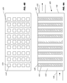
- FIGS. 3A and 3B illustrate cross sectional side and top views, respectively, of a filtration device with housing in the form of removable adsorptive tubes for high solid matters removal;
- FIGS. 4A and 4B illustrate cross sectional side and top views, respectively, of a filtration device with housing in the form of non-removable adsorptive tubes for high solid matters removal;
- FIGS. 5A , 5 B and 5 C illustrate cross sectional side, top, and front views, respectively, of a filtration device with housing in the form removable adsorptive slates for high solid matters removal;
- FIGS. 6A , 6 B and 6 C illustrate cross sectional side, top and front views, respectively, of a filtration device with housing in the form of non-removable adsorptive slates for high solid matters removal.
- Filtration devices of the present invention are particularly effective in removing contaminants from process streams.
- One source of the contaminants is the corrosion of process equipment and another source is the presence of active species in the process streams that ultimately lead to the formation of polar polymeric sludge. It has been demonstrated that these contaminants are paramagnetic in nature and therefore are attracted to magnets.
- the contaminants generally comprise a mixture of different materials are acidic, low in pH, black and viscous, and tend to deposit throughout the process lines, including filters, heat exchangers, catalyst beds, thereby reducing process capacity and efficiency.
- Magnetic intensity is temperature dependent. High temperatures can lead to a reduction in the magnetic field strength so it is preferable to avoid excessive operating temperatures which would rendering the filtration apparatus less efficient. Conversely, low temperatures operations are to be avoid especially during the cleaning stage otherwise, the paramagnetic matters will adhere to the stainless steel adsorptive housing surface too strongly so that contaminants do not readily fall off after the magnetic field is removed.
- the operating temperatures for the filtration devices typically range from 10 to 200° C., and preferably from 20 to 150° C.
- the superficial velocity of the process stream passing through the filtration devices typically ranges from 10 to 10,000 v/v/Hr, and preferably from 50 to 5,000 v/v/Hr.
- the pressure drop across the filtration device is an indicator of its remaining capacity. As the pressure drop reaches between 1 to 10 Kg/Cm 2 , and preferably between 1 to 5 Kg/Cm 2 , the filtration device should be removed from the service and cleaned.
- the present invention provides a continuous filtration device designed specifically for chemical process streams that contain relatively small amounts of solid matters and active substances that are responsible for generating polymerized sludge or corrosion byproducts.
- a novel filtration device is applied to rejuvenate the extraction solvent in the circulation loop of an aromatic extraction process.
- This continuous filtration device can rejuvenate the contaminated extraction solvent by removing degradation and corrosion products from the solvent stream continuously without interruption thereby achieving high capacity and operation efficiency for the aromatic extraction process.
- the workload of the existing, high-cost solvent regenerator is substantially reduced and the level of messy, hazardous solid sludge is substantially reduced as well.
- a preferred example of the extraction solvent is sulfolane.
- FIGS. 1A and 1B comprises a high-pressure vessel 102 defining a compartment 116 that is sealed from the environment with a removable top cover 104 .
- a supporting tray 108 is positioned within compartment 116 to accommodate a plurality of magnet housings 114 .
- Supporting tray 108 is preferably configured as a rack with a round circumference that matches the contour of compartment 116 .
- Each magnet housing 114 encases a magnetic bar 110 that has been removably inserted therein.
- Each magnet housing which serves to isolate magnet bar 110 from direct contact with the contaminated process stream, is configured as a vertically elongated stainless steel tube with a square cross section and the plurality of tubes form a circular arrangement that is held by supporting tray 108 .
- the number of housings 114 and associated magnetic bars 110 employed in filtration device 100 typically ranges from 1 to 30 or more.
- a spring 106 is positioned between top cover 104 and inner cover 118 , which is on the plurality of housing 114 , to maintain the position of plurality of housing 114 within compartment 116 .
- a fine mesh screen cylinder 112 which is configured as a basket made from metallic mesh material, is installed in the lower part of compartment 116 and encloses the plurality of magnet housing 114 .
- the plurality of magnet housing 114 fits within the inner perimeter of screen cylinder 112 .
- contaminated a process stream containing sulfolane solvent enters filtration device 100 through inlet 130 and the flow of the solvent is channeled initially toward the lower end of compartment 116 so that the contaminated solvent flows through screen cylinder 112 pass the plurality of magnet housing 114 before the treated solvent exits through outlet 132 .
- the degradation and corrosion products are attracted and adhere to the stainless steel tubes of housing 114 with the aid of powerful magnetic bars 110 .
- the removal of the degradation and corrosion products by the magnetic bar is enhanced by the presence of inner screen cylinder 112 that distributes the flow of solvent more evenly over the plurality of magnet housing 114 . This enhancement becomes crucial when the level of residual degradation and corrosion products are to be kept to a minimum.
- the rejuvenated clean extraction solvent can be recycled back to the extraction column.
- the filtration device After being on-stream for a certain period of time, the filtration device becomes loaded with the degradation and corrosion products and the pressure drop across the device increases.
- the stream is then switched to an auxiliary filtration device that has been installed in a parallel position with the on-stream device.
- Supporting tray 108 is lifted from compartment 116 along with the plurality of housing 114 that encases magnetic bars 110 .
- Supporting tray 108 is first placed in a container and upon removal of magnetic bars 110 from housing 114 , the attracted contaminants simply fall off the surface of housing 114 with the loss of the attractive force.
- This configuration of the filtration device is characterized by high efficiency for contaminants removal, simple construction and low maintenance costs.
- FIGS. 2A and 2B show a modified version of the filtration device that includes magnet housing that is integral with the unit and is not removable therein.
- filtration device 200 comprises a high-pressure vessel 202 that includes a process stream inlet 230 and a process stream outlet 232 . Except for the inlet and outlet, compartment 216 of filtration device 200 is enclosed from the environment.
- a plurality stationary magnet housing 214 configured as vertically elongated stainless steel tubes arranged in a circular fashion within compartment 216 .
- Each magnet housing 214 has an aperture on the sealed surface 204 of filtration device 200 so that housing 214 is as an integral part of the high-pressure vessel.
- Magnetic bars 210 are placed into magnet housing 214 from the outside.
- the contaminated stream is switched to a bypass line that is installed in parallel to filter 200 .
- Magnetic bars 210 are removed from housing 214 ; upon removal of the magnetic bars, the attracted contaminants fall from outside of the vertical tubes due to the loss of the attractive force.
- the collected contaminant sludge is flushed from the filtration device with a diluent fluid, such as water or other low value stream. Once the magnetic bars are reinserted into the housing, the cleaned filtration device is for service.
- This simple design is especially attractive when the contaminants or the process stream is hazardous as it is not necessary to open and disassemble the filtration device or any other process equipment in order to remove the adsorbed contaminants from the device.
- the filtration devices depicted in FIGS. 1 and 2 can be designed specifically for any chemical process stream, similar to the sulfolane solvent stream, which contains relatively smaller among of solid matters and active contaminants responsible for generating polymerized sludge or corrosion products.
- the present invention provides continuous filtration devices designed specifically for the refinery process streams that contain relatively larger amounts of solid matters, active substances which are responsible for generating polymerized sludge or corrosion products, and/or contaminants which are undesirable to the down-stream process unit.
- the solid matter in the front-end process streams of refineries usually contains a significant amount of iron rust particulates and other degradation and corrosion products, which tend to accumulate in process lines, valves, and pumps.
- filtration devices with greater filtration capacity that is, equipped with more and/or larger magnetic bars, are required.
- the filtration device as shown in FIGS. 3A and 3B is, for example, applied to remove contaminants from straight-run gas oil before it is fed into a hydrodesulfurization (HDS) unit in the refinery.
- This filtration device can effectively replace the inefficient conventional filter and better protect the sophisticated panel heat exchanger, e.g., PACKINOX heat exchanger, and the catalyst bed of the HDS unit. Both the PACKINOX heat exchanger and the catalyst bed are vulnerable to plugging by iron rust and other paramagnetic particulates.
- Filtration device 300 cleans the gas oil by continuously removing iron rust particulates and other corrosion products from the stream. Thus a high capacity and operation efficiency of the PACKINOX heat exchanger and the HDS unit are maintained.
- filtration device 300 comprises a high-pressure vessel 302 with a removable cover 304 that is equipped with handle 306 , and a square or rectangular rack-shaped supporting tray 308 with magnet housing 314 in the form of vertically elongated stainless steel square tubes fitted within compartment 316 of high pressure vessel 302 .
- the stainless steel square tubes are preferably arranged in rows in a square or a rectangular matrix to increase the total contact area of the tubes for maximum solid loading.
- a magnetic bar 310 is placed in each stainless steel tube.
- vertical partition plates 320 are placed between each row of the tubes to create a tortuous flow pattern pass the tubes.
- the number of housings 314 and associated magnetic bars 310 employed in filtration device 300 typically ranges from 1 to 100 or more.
- FIGS. 4A and 4B depict a modified version of the filtration device that includes magnet housing that is integral with the unit and is not removable therein.
- filtration device 400 comprises a high-pressure vessel 402 with a plurality of magnet housing 414 in the form of stationary vertically elongated square stainless steel tubes arranged in rows of a square or rectangle matrix. The tubes are an integral part of the high-pressure vessel.
- a magnetic bar 410 is placed inside each square stainless steel tube through an orifice on upper sealed surface of pressure-vessel 402 .
- Vertical partition plates 420 are placed between each row of the tubes to optimize flow pattern through compartment 416 .
- FIGS. 5A , 5 B, and 5 C illustrate another filtration device that is particularly suited for removing contaminants from refinery streams, such as the straight-run gas oil before it enters a HDS unit, and thereby maintain the high capacity and operation efficiency of the down-stream PACKINOX heat exchanger and the HDS unit.
- filtration device 500 comprises a high-pressure vessel 502 sealed with a removable cover 504 that is equipped with handle 506 , and a square or rectangular-shaped rack supporting tray 508 to which a plurality of magnet housing 514 in the form of vertically elongated stainless steel column or slates are attached and fitted in compartment 516 of high pressure vessel 502 .
- the stainless steel slates are arranged in parallel rows to increase the total contact surface area of the device for maximum solid loading.
- the space between adjacent parallel rows of slates defines a channel through which the contaminated gas oil flow.
- a magnetic plate 510 is placed inside of each stainless steel slate.
- the number of housings 514 and associated magnetic bars 510 employed in filtration device 500 typically ranges from 1 to 100 or more.
- contaminated gas oil enters filtration device 502 through inlets 530 located at the lower part on the front side of the device.
- the iron rust particulates and corrosion products are attracted and adhere to the outside surface of the vertical stainless steel slates with the aid of the powerful magnetic plates.
- the cleaned gas oil stream exits through an outlet 532 located in the upper part of backside of the device.
- inlets 530 and outlets 532 define flow patterns that are parallel to the channels between adjacent slates.
- the employment of multiple inlets better distributes the process stream flow so as to maximize the contact time between the process stream and slates.
- filtration device 500 is taken off-line, supporting tray 508 is lifted from compartment 516 and once the magnetic plates are removed from their corresponding stainless steel slates, the contaminants will fall off.
- FIGS. 6A , 6 B and 6 C depict a modified version of the filtration device that includes magnet housing that is integral with the unit and is not removable therein.
- filtration device 600 comprises a high-pressure vessel 602 that defines compartment 616 into which are positioned a plurality of magnet housing 614 in the form of stationary vertically elongated stainless steel column or slates that are arranged in parallel across compartment 616 .
- the slates are an integral part of the high-pressure vessel.
- compartment 616 is sealed from the environment.
- a vertical magnetic plate 610 is placed into each of magnet housing 614 through an aperture on sealed top 622 of pressure-vessel 602 .
- filtration device 600 Operation of filtration device 600 is similar to that shown in FIGS. 5A , 5 B and 5 C however once filtration device 600 is taken off-line, the magnetic plates are simply lifted out of their stainless steel slate housings whereupon the contaminants fall off into compartment 616 . The adsorbed contaminant sludge is flushed away.
- Filtration devices of the present invention can be adapted for implementation to any refining process stream, similar to the straight-run gas oil stream, which contains relatively large among of iron rust particulates, corrosive products, and/or contaminants, which are undesirable to the down-stream process unit.
- the filtration devices of this invention can be advantageously applied to following refinery streams: (1) feed to the C 5 and C 6 isomerization unit, (2) feed to the naphtha HDS unit, (3) feed to the reformer HDS unit, (4) feed to the kerosene HDS unit, (5) feed to the coke naphtha HDS unit, (6) feed to residual oil HDS unit, and (7) feed to coal tar naphtha HDS unit.
Abstract
Description
Claims (16)
Priority Applications (1)
| Application Number | Priority Date | Filing Date | Title |
|---|---|---|---|
| US13/470,340 US9080112B2 (en) | 2008-04-30 | 2012-05-13 | Filtration method for refining and chemical industries |
Applications Claiming Priority (3)
| Application Number | Priority Date | Filing Date | Title |
|---|---|---|---|
| US12/112,623 US20090272702A1 (en) | 2008-04-30 | 2008-04-30 | Process and apparatus for online rejuvenation of contaminated sulfolane solvent |
| US12/589,314 US20100065504A1 (en) | 2008-04-30 | 2009-10-21 | Novel filtration method for refining and chemical industries |
| US13/470,340 US9080112B2 (en) | 2008-04-30 | 2012-05-13 | Filtration method for refining and chemical industries |
Related Parent Applications (1)
| Application Number | Title | Priority Date | Filing Date |
|---|---|---|---|
| US12/589,314 Division US20100065504A1 (en) | 2008-04-30 | 2009-10-21 | Novel filtration method for refining and chemical industries |
Publications (2)
| Publication Number | Publication Date |
|---|---|
| US20120228231A1 US20120228231A1 (en) | 2012-09-13 |
| US9080112B2 true US9080112B2 (en) | 2015-07-14 |
Family
ID=43425902
Family Applications (2)
| Application Number | Title | Priority Date | Filing Date |
|---|---|---|---|
| US12/589,314 Abandoned US20100065504A1 (en) | 2008-04-30 | 2009-10-21 | Novel filtration method for refining and chemical industries |
| US13/470,340 Active - Reinstated 2029-08-23 US9080112B2 (en) | 2008-04-30 | 2012-05-13 | Filtration method for refining and chemical industries |
Family Applications Before (1)
| Application Number | Title | Priority Date | Filing Date |
|---|---|---|---|
| US12/589,314 Abandoned US20100065504A1 (en) | 2008-04-30 | 2009-10-21 | Novel filtration method for refining and chemical industries |
Country Status (8)
| Country | Link |
|---|---|
| US (2) | US20100065504A1 (en) |
| EP (1) | EP2491098A1 (en) |
| JP (1) | JP5521050B2 (en) |
| KR (1) | KR101481247B1 (en) |
| CN (1) | CN102597175B (en) |
| MY (1) | MY158521A (en) |
| TW (1) | TWI439314B (en) |
| WO (1) | WO2011049788A1 (en) |
Cited By (1)
| Publication number | Priority date | Publication date | Assignee | Title |
|---|---|---|---|---|
| US9352331B1 (en) | 2015-09-26 | 2016-05-31 | Allnew Chemical Technology Company | Filters for paramagnetic and diamagnetic substances |
Families Citing this family (21)
| Publication number | Priority date | Publication date | Assignee | Title |
|---|---|---|---|---|
| US8246815B2 (en) | 2010-08-10 | 2012-08-21 | Amt International Inc. | Methods for regeneration of solvents for extractive processes |
| US9440947B2 (en) | 2012-02-26 | 2016-09-13 | Amt International, Inc. | Regeneration of selective solvents for extractive processes |
| US8663461B2 (en) | 2012-03-05 | 2014-03-04 | Amt International, Inc. | Extraction process with novel solvent regeneration methods |
| US8900449B2 (en) | 2012-03-13 | 2014-12-02 | Cpc Corporation, Taiwan | Magnetic filter for refining and chemical industries |
| DE102014003885A1 (en) | 2013-03-27 | 2014-10-02 | Mann + Hummel Gmbh | Magnetic filter medium and method for its production |
| US8636907B1 (en) | 2013-05-09 | 2014-01-28 | Amt International, Inc. | Sealed magnetic filter for hazardous operations and easy clean service |
| JP2014229567A (en) * | 2013-05-24 | 2014-12-08 | 日揮触媒化成株式会社 | Method of manufacturing positive electrode active material |
| CN103464283B (en) * | 2013-09-25 | 2016-01-27 | 云南大红山管道有限公司 | A kind of Magnetic field screening separator and beneficiation method thereof |
| CN104128257A (en) * | 2014-08-03 | 2014-11-05 | 广西北流市智诚陶瓷自动化科技有限公司 | Multi-degree-of-freedom magnetic iron removal device |
| KR102349698B1 (en) * | 2015-01-29 | 2022-01-12 | 에스케이온 주식회사 | Magnetic filter |
| NO341809B1 (en) | 2015-03-30 | 2018-01-29 | Sapeg As | Device for capturing and removing magnetic material in a flow of material |
| CN104874479A (en) * | 2015-06-02 | 2015-09-02 | 重庆国际复合材料有限公司 | Glass fiber impregnating compound iron removing and filter device |
| CN105536986A (en) * | 2016-02-01 | 2016-05-04 | 飞龙精工科技(苏州)有限公司 | Filtering system |
| GB201605181D0 (en) * | 2016-03-24 | 2016-05-11 | Air Bp Ltd | Magnetic filters |
| CN105864189A (en) * | 2016-05-12 | 2016-08-17 | 绍兴文理学院 | Hydraulic wave filtering method for full-band variable structure |
| CN105840855B (en) * | 2016-05-12 | 2018-02-23 | 陕西科技大学 | A kind of automatic clearing apparatus and method that prevent irony debris from entering fiberizer |
| CN105889184A (en) * | 2016-05-12 | 2016-08-24 | 绍兴文理学院 | Oil filtering method adopting filter, magnetization and adsorption |
| US11713424B2 (en) * | 2018-02-14 | 2023-08-01 | Chevron Phillips Chemical Company, Lp | Use of Aromax® catalyst in sulfur converter absorber and advantages related thereto |
| NO344126B1 (en) | 2018-04-20 | 2019-09-09 | Jagtech As | Cleaning assembly for magnet assemblies |
| CN109622221B (en) * | 2018-12-26 | 2020-05-08 | 福州兴顺达环保科技有限公司 | Waste metal collecting device in sewage |
| KR102629120B1 (en) * | 2020-11-09 | 2024-01-24 | 주식회사 엘지화학 | Method for removing metalic material in petrochemical product |
Citations (20)
| Publication number | Priority date | Publication date | Assignee | Title |
|---|---|---|---|---|
| US2385431A (en) * | 1944-01-29 | 1945-09-25 | Sun Oil Co | Process for refining of hydrocarbon oil with metallic sodium |
| US2459534A (en) * | 1945-03-23 | 1949-01-18 | J A Zurn Mfg Co | Magnetic separator for fluid systems |
| US3143496A (en) * | 1962-02-08 | 1964-08-04 | Cons Edison Co New York Inc | Magnetic filter apparatus and method |
| US3195728A (en) * | 1958-09-12 | 1965-07-20 | Sommermeyer Heinrich | Magnetic fluid filter |
| US3448040A (en) * | 1967-10-13 | 1969-06-03 | Phillips Petroleum Co | Adduct type hydrocarbon separation without filtration with a sulfolane solvent |
| US4067810A (en) * | 1976-02-09 | 1978-01-10 | Ofco, Inc. | Fluid filter magnet assembly |
| US4298456A (en) * | 1980-07-22 | 1981-11-03 | Phillips Petroleum Company | Oil purification by deasphalting and magneto-filtration |
| US4619770A (en) * | 1985-01-07 | 1986-10-28 | Phillips Petroleum Company | Method and apparatus for recovering a fluid from a filter |
| US4764278A (en) * | 1986-11-20 | 1988-08-16 | Shell Oil Company | Process for reducing the concentration of haloorganic compounds in water |
| US4783266A (en) * | 1987-08-10 | 1988-11-08 | Titch Duwayne E | Filter for removing particles from a fluid, and method therefore |
| US4944917A (en) * | 1982-07-14 | 1990-07-31 | Exxon Research And Engineering Company | Use of thiosulfate salt for corrosion inhibition in acid gas scrubbing processes |
| US4946589A (en) * | 1987-02-27 | 1990-08-07 | Combustion Engineering, Inc. | High volume permanent magnet filter for removing ferromagnetic impurities |
| US5043063A (en) * | 1990-03-21 | 1991-08-27 | Eriez Manufacturing Company | Magnetic trap and cleaning means therefor |
| US5188239A (en) * | 1991-06-17 | 1993-02-23 | Industrial Magnetics, Inc. | Tramp metal separation device |
| US5571408A (en) * | 1995-04-21 | 1996-11-05 | Rising; William R. | Compound clarification system |
| US5637226A (en) * | 1995-08-18 | 1997-06-10 | Az Industries, Incorporated | Magnetic fluid treatment |
| DE19717869A1 (en) * | 1997-04-28 | 1997-12-04 | Gehrt Manfred | Heating system water filter assembly |
| US20040182769A1 (en) * | 2003-03-19 | 2004-09-23 | Fogel Richard Edward | Multi-chamber magnetic filter |
| US20070068862A1 (en) * | 2005-09-23 | 2007-03-29 | Sisemore Stanley L | Device for focusing a magnetic field to treat fluids in conduits |
| US20090255853A1 (en) * | 2008-04-10 | 2009-10-15 | Cpc Corporation | Novel energy efficient and throughput enhancing extractive process for aromatics recovery |
Family Cites Families (19)
| Publication number | Priority date | Publication date | Assignee | Title |
|---|---|---|---|---|
| GB557626A (en) | 1942-05-19 | 1943-11-29 | Neill James & Co Sheffield Ltd | Improvements in or relating to magnetic separators |
| US3985648A (en) | 1974-06-27 | 1976-10-12 | Almag Pollution Control Corporation | Method and system for purifying liquid |
| US3953324A (en) | 1974-12-04 | 1976-04-27 | Shell Oil Company | Removal of solvent |
| US4357237A (en) * | 1979-11-28 | 1982-11-02 | Sanderson Charles H | Device for the magnetic treatment of water and liquid and gaseous fuels |
| JPS5783794A (en) | 1980-09-17 | 1982-05-25 | Schloemann Siemag Ag | Apparatus for cleaning lubricant and/or cooling liquid |
| JPS6254790A (en) * | 1985-05-08 | 1987-03-10 | Nippon Oil Co Ltd | Method of removing iron contained in mineral oil derived from petroleum |
| US4722788A (en) | 1985-05-25 | 1988-02-02 | Ishikawajima-Harima Jukogyo Kabushiki Kaisha | Magnetic filter |
| JPS621425A (en) * | 1985-06-24 | 1987-01-07 | Ishikawajima Harima Heavy Ind Co Ltd | Filtering and desalting apparatus |
| US4919816A (en) * | 1989-01-31 | 1990-04-24 | Sun Refining And Marketing Company | Removal of acidic impurities in processes for solvent extraction of aromatics from nonaromatics |
| US5053137A (en) | 1989-08-21 | 1991-10-01 | Indian Petrochemicals Corporation Limited | Process for the purification or regeneration of contaminated or spent process sulfolane |
| JP2673040B2 (en) * | 1990-10-17 | 1997-11-05 | 今井産業株式会社 | Filter |
| JPH0770568A (en) * | 1993-09-03 | 1995-03-14 | Nippon Oil Co Ltd | Removing method for irony impurities from petroleum heavy oil |
| US5411659A (en) * | 1994-03-04 | 1995-05-02 | Nichols; Bret E. | Reusable liquid filtering system |
| JPH08117517A (en) * | 1994-10-19 | 1996-05-14 | Miyawaki Inc | Strainer of fluid passage |
| US6730217B2 (en) * | 2002-03-29 | 2004-05-04 | Insul-Magnetics, Inc. | Magnetic particle separator and method |
| JP2005296740A (en) * | 2004-04-08 | 2005-10-27 | Sumitomo Chemical Co Ltd | Magnetic filter |
| JP2007229665A (en) * | 2006-03-02 | 2007-09-13 | Shimonishi Seisakusho:Kk | Strainer apparatus |
| US20080021179A1 (en) * | 2006-06-30 | 2008-01-24 | Mul Wilhelmus P | Catalytic chemical reaction process |
| JP5459943B2 (en) * | 2007-08-29 | 2014-04-02 | 株式会社ブンリ | Filtration device |
-
2009
- 2009-10-21 US US12/589,314 patent/US20100065504A1/en not_active Abandoned
-
2010
- 2010-10-12 CN CN201080042372.0A patent/CN102597175B/en active Active
- 2010-10-12 JP JP2012535239A patent/JP5521050B2/en not_active Expired - Fee Related
- 2010-10-12 WO PCT/US2010/052370 patent/WO2011049788A1/en active Application Filing
- 2010-10-12 EP EP10773187A patent/EP2491098A1/en not_active Withdrawn
- 2010-10-12 MY MYPI2012001778A patent/MY158521A/en unknown
- 2010-10-12 KR KR1020127012838A patent/KR101481247B1/en not_active IP Right Cessation
- 2010-10-13 TW TW099134840A patent/TWI439314B/en active
-
2012
- 2012-05-13 US US13/470,340 patent/US9080112B2/en active Active - Reinstated
Patent Citations (21)
| Publication number | Priority date | Publication date | Assignee | Title |
|---|---|---|---|---|
| US2385431A (en) * | 1944-01-29 | 1945-09-25 | Sun Oil Co | Process for refining of hydrocarbon oil with metallic sodium |
| US2459534A (en) * | 1945-03-23 | 1949-01-18 | J A Zurn Mfg Co | Magnetic separator for fluid systems |
| US3195728A (en) * | 1958-09-12 | 1965-07-20 | Sommermeyer Heinrich | Magnetic fluid filter |
| US3143496A (en) * | 1962-02-08 | 1964-08-04 | Cons Edison Co New York Inc | Magnetic filter apparatus and method |
| US3448040A (en) * | 1967-10-13 | 1969-06-03 | Phillips Petroleum Co | Adduct type hydrocarbon separation without filtration with a sulfolane solvent |
| US4067810A (en) * | 1976-02-09 | 1978-01-10 | Ofco, Inc. | Fluid filter magnet assembly |
| US4298456A (en) * | 1980-07-22 | 1981-11-03 | Phillips Petroleum Company | Oil purification by deasphalting and magneto-filtration |
| US4944917A (en) * | 1982-07-14 | 1990-07-31 | Exxon Research And Engineering Company | Use of thiosulfate salt for corrosion inhibition in acid gas scrubbing processes |
| US4619770A (en) * | 1985-01-07 | 1986-10-28 | Phillips Petroleum Company | Method and apparatus for recovering a fluid from a filter |
| US4764278A (en) * | 1986-11-20 | 1988-08-16 | Shell Oil Company | Process for reducing the concentration of haloorganic compounds in water |
| US4946589A (en) * | 1987-02-27 | 1990-08-07 | Combustion Engineering, Inc. | High volume permanent magnet filter for removing ferromagnetic impurities |
| US4783266A (en) * | 1987-08-10 | 1988-11-08 | Titch Duwayne E | Filter for removing particles from a fluid, and method therefore |
| US5043063A (en) * | 1990-03-21 | 1991-08-27 | Eriez Manufacturing Company | Magnetic trap and cleaning means therefor |
| US5188239A (en) * | 1991-06-17 | 1993-02-23 | Industrial Magnetics, Inc. | Tramp metal separation device |
| US5571408A (en) * | 1995-04-21 | 1996-11-05 | Rising; William R. | Compound clarification system |
| US5637226A (en) * | 1995-08-18 | 1997-06-10 | Az Industries, Incorporated | Magnetic fluid treatment |
| DE19717869A1 (en) * | 1997-04-28 | 1997-12-04 | Gehrt Manfred | Heating system water filter assembly |
| US20040182769A1 (en) * | 2003-03-19 | 2004-09-23 | Fogel Richard Edward | Multi-chamber magnetic filter |
| US20070068862A1 (en) * | 2005-09-23 | 2007-03-29 | Sisemore Stanley L | Device for focusing a magnetic field to treat fluids in conduits |
| US20090255853A1 (en) * | 2008-04-10 | 2009-10-15 | Cpc Corporation | Novel energy efficient and throughput enhancing extractive process for aromatics recovery |
| US7879225B2 (en) * | 2008-04-10 | 2011-02-01 | CPC Corporation Taiwan | Energy efficient and throughput enhancing extractive process for aromatics recovery |
Cited By (2)
| Publication number | Priority date | Publication date | Assignee | Title |
|---|---|---|---|---|
| US9352331B1 (en) | 2015-09-26 | 2016-05-31 | Allnew Chemical Technology Company | Filters for paramagnetic and diamagnetic substances |
| WO2017053103A1 (en) | 2015-09-26 | 2017-03-30 | Allnew Chemical Technology Company | Filters for paramagnetic and diamagnetic substances |
Also Published As
| Publication number | Publication date |
|---|---|
| US20120228231A1 (en) | 2012-09-13 |
| US20100065504A1 (en) | 2010-03-18 |
| EP2491098A1 (en) | 2012-08-29 |
| KR101481247B1 (en) | 2015-01-09 |
| JP2013508508A (en) | 2013-03-07 |
| WO2011049788A1 (en) | 2011-04-28 |
| MY158521A (en) | 2016-10-14 |
| JP5521050B2 (en) | 2014-06-11 |
| TWI439314B (en) | 2014-06-01 |
| KR20120083549A (en) | 2012-07-25 |
| CN102597175A (en) | 2012-07-18 |
| CN102597175B (en) | 2016-02-17 |
| TW201117873A (en) | 2011-06-01 |
Similar Documents
| Publication | Publication Date | Title |
|---|---|---|
| US9080112B2 (en) | Filtration method for refining and chemical industries | |
| US8506820B2 (en) | Process and apparatus for online rejuvenation of contaminated sulfolane solvent | |
| US8900449B2 (en) | Magnetic filter for refining and chemical industries | |
| US5087374A (en) | Removal of contaminates from granular solids | |
| EP0626440B1 (en) | Fine magnetic particle-containing stock oil supply system | |
| WO2014182424A1 (en) | Sealed magnetic filter for hazardous operations and easy clean-up service | |
| JP5521049B2 (en) | Method and apparatus for regenerating contaminated sulfolane solvent in line | |
| CN105664528A (en) | Treatment of contaminated liquids | |
| TWI421247B (en) | Online process for rejubenating whole stream of contaminated lean sulfolane in an extraction system | |
| RU2328331C2 (en) | Method of filtering plant operation and kudryavtsev filtering plant | |
| KR100433754B1 (en) | Cleaning method of Contaminated Ion Exchange Resin | |
| RU2320544C2 (en) | Method for purifying of liquids such as recycling and source water, industrial sewage, process liquids, and complex for performing the same | |
| US5068029A (en) | Two-chamber fluid/solids treatment vessel | |
| CN220238013U (en) | Sulfolane solution purifying device | |
| CN212712973U (en) | Treatment system for cutting waste liquid | |
| RU21912U1 (en) | WATER TREATMENT PLANT | |
| RU2341407C1 (en) | Method for purification of bilge and sewage waters from oil products and other contaminants and device for its realisation | |
| KR101277729B1 (en) | Apparatus for testing fluid treatment | |
| RU2286198C1 (en) | Method for purification of recycled and sewage water and module cassette-type purifier for effectuating the same | |
| RU2621754C1 (en) | Method of absorption cleaning of hydrocarbon gas from acid components | |
| KR101267311B1 (en) | Wastewater treatment system using absorption and filtration and method thereof | |
| RU21911U1 (en) | FILTER INSTALLATION |
Legal Events
| Date | Code | Title | Description |
|---|---|---|---|
| AS | Assignment |
Owner name: CPC CORPORATION, TAIWAN, TAIWAN Free format text: ASSIGNMENT OF ASSIGNORS INTEREST;ASSIGNORS:YEN, PING-WEN;HO, YUH-SHEVE;CHIU, HUNG-TZU;AND OTHERS;REEL/FRAME:028199/0245 Effective date: 20091022 |
|
| STCF | Information on status: patent grant |
Free format text: PATENTED CASE |
|
| FEPP | Fee payment procedure |
Free format text: MAINTENANCE FEE REMINDER MAILED (ORIGINAL EVENT CODE: REM.); ENTITY STATUS OF PATENT OWNER: LARGE ENTITY |
|
| LAPS | Lapse for failure to pay maintenance fees |
Free format text: PATENT EXPIRED FOR FAILURE TO PAY MAINTENANCE FEES (ORIGINAL EVENT CODE: EXP.); ENTITY STATUS OF PATENT OWNER: LARGE ENTITY |
|
| STCH | Information on status: patent discontinuation |
Free format text: PATENT EXPIRED DUE TO NONPAYMENT OF MAINTENANCE FEES UNDER 37 CFR 1.362 |
|
| FP | Lapsed due to failure to pay maintenance fee |
Effective date: 20190714 |
|
| PRDP | Patent reinstated due to the acceptance of a late maintenance fee |
Effective date: 20200409 |
|
| FEPP | Fee payment procedure |
Free format text: PETITION RELATED TO MAINTENANCE FEES GRANTED (ORIGINAL EVENT CODE: PMFG); ENTITY STATUS OF PATENT OWNER: LARGE ENTITY Free format text: PETITION RELATED TO MAINTENANCE FEES FILED (ORIGINAL EVENT CODE: PMFP); ENTITY STATUS OF PATENT OWNER: LARGE ENTITY Free format text: SURCHARGE, PETITION TO ACCEPT PYMT AFTER EXP, UNINTENTIONAL (ORIGINAL EVENT CODE: M1558); ENTITY STATUS OF PATENT OWNER: LARGE ENTITY |
|
| MAFP | Maintenance fee payment |
Free format text: PAYMENT OF MAINTENANCE FEE, 4TH YEAR, LARGE ENTITY (ORIGINAL EVENT CODE: M1551); ENTITY STATUS OF PATENT OWNER: LARGE ENTITY Year of fee payment: 4 |
|
| STCF | Information on status: patent grant |
Free format text: PATENTED CASE |
|
| MAFP | Maintenance fee payment |
Free format text: PAYMENT OF MAINTENANCE FEE, 8TH YEAR, LARGE ENTITY (ORIGINAL EVENT CODE: M1552); ENTITY STATUS OF PATENT OWNER: LARGE ENTITY Year of fee payment: 8 |