JP2005296740A - Magnetic filter - Google Patents
Magnetic filter Download PDFInfo
- Publication number
- JP2005296740A JP2005296740A JP2004113946A JP2004113946A JP2005296740A JP 2005296740 A JP2005296740 A JP 2005296740A JP 2004113946 A JP2004113946 A JP 2004113946A JP 2004113946 A JP2004113946 A JP 2004113946A JP 2005296740 A JP2005296740 A JP 2005296740A
- Authority
- JP
- Japan
- Prior art keywords
- tube
- magnetic filter
- magnetic
- filter
- analyzer
- Prior art date
- Legal status (The legal status is an assumption and is not a legal conclusion. Google has not performed a legal analysis and makes no representation as to the accuracy of the status listed.)
- Pending
Links
Images
Landscapes
- Sampling And Sample Adjustment (AREA)
Abstract
【課題】 液体中に含まれる磁気粒子を連続的に除去することができ、小型で、かつ、メンテナンスの容易な磁気フィルターを提供する。本発明によると、分析器に使用した場合、分析器内のフィルター等の閉塞、構成部品の磨耗による計測誤差等が解消できる。
【解決手段】 着脱可能な磁石を管の外部に配置し、管内部に強磁性材料からなるエレメントを収容し、管の両端を外径の異なる管と接続可能にし、かつ、内部に収容されたエレメントの取り出しを容易にしたことを特徴とする磁気フィルターである。請求項2に係る発明は、前記磁気フィルターのエレメントが鋼球である磁気フィルターであり、請求項3に係る発明は、前記磁気フィルターのエレメントを収容する管が樹脂材料又は透明なガラス等によりなっている磁気フィルター
【選択図】 図1
PROBLEM TO BE SOLVED: To provide a small and easy maintenance magnetic filter capable of continuously removing magnetic particles contained in a liquid. According to the present invention, when used in an analyzer, it is possible to eliminate blockage of a filter or the like in the analyzer, measurement error due to wear of components, and the like.
SOLUTION: A removable magnet is disposed outside a tube, an element made of a ferromagnetic material is accommodated inside the tube, and both ends of the tube can be connected to a tube having a different outer diameter, and are accommodated inside the tube. The magnetic filter is characterized in that the element can be easily taken out. The invention according to claim 2 is a magnetic filter in which the element of the magnetic filter is a steel ball, and the invention according to claim 3 is that the tube that houses the element of the magnetic filter is made of a resin material or transparent glass. Magnetic filter [selection] Fig. 1
Description
本発明は、例えば合成化学プロセスにおいて微量の磁性粒子を含む有機化合物を連続的に採取し、プロセス分析に供する場合等に有用な小型の磁気フィルターに関するものである。 The present invention relates to a small magnetic filter that is useful when, for example, an organic compound containing a small amount of magnetic particles in a synthetic chemical process is continuously collected and used for process analysis.
合成化学プロセスにおいては、目的とする化合物の他に多くの副生成物が生成するのが通常である。また、微量の触媒残渣が流出し磁性粒子として混入してくることもある。従来、磁気フィルターとしては、多管式のドラム中に強磁性材料により形成されたエレメントを収容し、管の中に棒状の永久磁石を挿入して、出し入れを可能にした磁気フィルター(特許文献1参照)や流体が流れる流路内に磁石で強力な磁場をかけ、磁気フィルターのエレメントを次第に収束するように流路に平行に配置して、磁気粒子を外部へ誘導して取り出す磁気分離装置(特許文献2参照)等が提案されている。これらはいずれも原子炉における冷却剤中の磁気を有する腐食生成物等を除去するための、大型装置に関するものである。しかし、合成化学プロセスにおいて、微量の磁性粒子を含む有機化合物のサンプルを連続的に採取し、プロセス分析に供する場合には、分析器内のフィルター等の閉塞、構成部品の磨耗等が計測へ影響を与えるため、磁気粒子を除去して分析する必要がある。このような場合の小型で、かつ、メンテナンスが容易な除去装置の開発が望まれていた。 In a synthetic chemical process, many by-products are usually generated in addition to the target compound. In addition, a small amount of catalyst residue may flow out and be mixed as magnetic particles. Conventionally, as a magnetic filter, an element formed of a ferromagnetic material is accommodated in a multi-tubular drum, and a rod-shaped permanent magnet is inserted into the tube to enable insertion and removal (Patent Document 1). A magnetic separation device (see below) and a magnetic field applied by a magnet in the flow path through which the fluid flows, and the magnetic filter elements are arranged parallel to the flow path so as to converge gradually, and the magnetic particles are guided out and taken out. Patent Document 2) has been proposed. These all relate to a large apparatus for removing magnetic corrosion products and the like in a coolant in a nuclear reactor. However, in the synthetic chemical process, when samples of organic compounds containing a small amount of magnetic particles are continuously collected and used for process analysis, clogging of the filter in the analyzer, wear of components, etc. will affect the measurement. Therefore, it is necessary to remove and analyze the magnetic particles. In such a case, it has been desired to develop a removal device that is small and easy to maintain.
本発明は、このような状況下でなされたものであって、液体中に含まれる磁気粒子を、連続的に除去することができる、小型で、かつ、メンテナンスの容易な磁気フィルターの提供を目的とする。 The present invention has been made under such circumstances, and it is an object of the present invention to provide a small and easy-to-maintain magnetic filter capable of continuously removing magnetic particles contained in a liquid. And
すなわち、請求項1に係る発明は、着脱可能な磁石を管の外部に配置し、管内部に強磁性材料からなるエレメントを収容し、管の両端を外径の異なる管と接続可能にし、かつ、内部に収容されたエレメントの取り出しを容易にしたことを特徴とする磁気フィルターである。請求項2に係る発明は、前記磁気フィルターのエレメントが鋼球である磁気フィルターであり、請求項3に係る発明は、前記磁気フィルターのエレメントを収容する管が樹脂材料又は透明なガラス等によりなっている磁気フィルターである。 That is, the invention according to claim 1 arranges a detachable magnet outside the tube, houses an element made of a ferromagnetic material inside the tube, makes both ends of the tube connectable to tubes having different outer diameters, and The magnetic filter is characterized by facilitating removal of the element accommodated therein. The invention according to claim 2 is a magnetic filter in which the element of the magnetic filter is a steel ball, and the invention according to claim 3 is that the tube that houses the element of the magnetic filter is made of a resin material or transparent glass. It is a magnetic filter.
本発明により、液体中に含まれる磁気粒子を連続的に除去することができ、小型で、かつ、メンテナンスの容易な磁気フィルターの提供が可能になった。その結果、分析器に使用した場合、分析器内のフィルター等の閉塞、構成部品の磨耗による計測誤差等が解消できる。 According to the present invention, it is possible to continuously remove magnetic particles contained in a liquid, and to provide a magnetic filter that is small and easy to maintain. As a result, when used in an analyzer, it is possible to eliminate blockage of filters and the like in the analyzer and measurement errors due to wear of components.
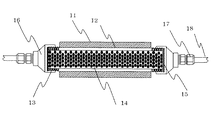
本発明が適用される磁気フィルターの構成の一例を示す図1に基づいて、具体的に本発明を説明する。図1に示した磁気フィルターは、永久磁石11、管12、管のねじ部分13、エレメント14、エレメントの押え15、レジューサー16、ユニオン17よりなっている。管12の外部には、永久磁石11が取付けられ、着脱自在になっている。磁石は、永久磁石に限らず電磁石を用いてもよいが、永久磁石を用いる方が簡便である。磁石の形状および取付け方法は、特に制限はなく、管の外部への固定・取り外しが容易にできるようにする。例えば、板状の磁石を管に沿わせるように配置し、その外側を板で押えてボルト・ナットで固定する方法、シート状の磁石を管に巻きつける方法、多数の小さい磁石を布状のもので包み込み、折り曲げが容易であるようにした磁石群を管に巻きつける方法等が好適に用いられる。
The present invention will be specifically described based on FIG. 1 showing an example of the configuration of a magnetic filter to which the present invention is applied. The magnetic filter shown in FIG. 1 includes a permanent magnet 11, a
管12は、強磁性体よりなる磁性体のエレメントを収容する管であって、エレメントが収容できる筒状の容器であればよい。通常は、非磁性体であるステンレス管が用いられるが、塩化ビニルパイプなどの合成樹脂管も用いることができる。管の直径および長さは、中に流す流体の流量に応じて選べばよいが、通常分析器具用に用いる場合は直径10〜30mmで、長さ100mm程度のものが用いられる。
The pipe |
管の中へ収容する磁性体のエレメント14は直径3mm程度の鋼球が、好適に用いられる。形状は、特に球状である必要はないが、エレメントに磁気を帯びさせて磁気粒子を捕捉するため、特別に複雑な形状は必要ではない。エレメントの押え15は、エレメントが外部へ漏れないようにするもので、金網等で押えればよい。管の両端には、ねじ部分13を設けて、レジューサー16をねじ込み、管径の異なる導管18を接続できるようにする。本発明の磁気フィルターは、上記のように構成されていることにより、磁気フィルターを洗浄する際には、着脱自在な磁石を外し、エレメントの磁気を解除して管内ブローをおこなうか、エレメントを取り出して洗浄し、エレメントに付着した磁気粒子を容易に除去すればよく、メンテナンスが容易な構造になっている。
As the
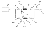
図2は、本発明の磁気フィルターの使用例を示す図である。この使用例は、微量の磁気粒子を含有するプロセス流体から、分析用サンプルを分岐して採取し、連続的に分析を行いプロセス管理を行う場合の接続例である。以下、符号にbを付したものは、予備器である。磁気フィルター21aを、分析器22に、切替用バルブ23aを介して接続する。プロセス流体サンプルは、導入管26から入口バルブ24a、磁気フィルター21aを経て分析器22、例えばプロセスガスクロマトグラフィー等に導入して連続分析を行う。圧力計27及び27aは、プロセス流体の圧力計測を行っており、その圧力差で磁気フィルター21aの汚れ具合を監視するものである。長期間使用し、磁気フィルターが汚れた場合には、b系列にバルブを切替る。その間、a系列の入口バルブ24aおよびブロー用バルブ25aを開けてプロセス流体でブローしながら磁気フィルター21aの掃除を行う。ブロー操作によって汚れが取れにくい場合には、磁気フィルター21aを取外し、内部のエレメントを取出して洗浄、交換等を行う。このように、外部に取付けた磁石の着脱が容易なこと、磁気フィルター本体と導管の接続・取外しが簡単であること、内部エレメントの取出し・洗浄が容易であること、予備器を設けて交互に使用することで化学プロセスの操業において連続的な計測が可能となる。
FIG. 2 is a diagram showing an example of use of the magnetic filter of the present invention. This use example is a connection example in a case where a sample for analysis is branched and collected from a process fluid containing a small amount of magnetic particles, continuously analyzed, and process management is performed. In the following, a symbol with b is a spare device. The
11…永久磁石、12…管、13…管のねじ部分、14…エレメント、15…エレメントの押え、16…レジューサー、17…ユニオン、18…導管、21a、21b…磁気フィルター、22…分析器、23a、23b…切替用バルブ、24a、24b…入口バルブ、25a、25b…ブロー用バルブ、26…導入管、27、27a、27b…圧力計
DESCRIPTION OF SYMBOLS 11 ... Permanent magnet, 12 ... Tube, 13 ... Screw part of tube, 14 ... Element, 15 ... Element presser, 16 ... Reducer, 17 ... Union, 18 ... Conduit, 21a, 21b ... Magnetic filter, 22 ... Analyzer , 23a, 23b ... Switching valve, 24a, 24b ... Inlet valve, 25a, 25b ... Blow valve, 26 ... Inlet pipe, 27, 27a, 27b ... Pressure gauge
Claims (3)
Priority Applications (1)
| Application Number | Priority Date | Filing Date | Title |
|---|---|---|---|
| JP2004113946A JP2005296740A (en) | 2004-04-08 | 2004-04-08 | Magnetic filter |
Applications Claiming Priority (1)
| Application Number | Priority Date | Filing Date | Title |
|---|---|---|---|
| JP2004113946A JP2005296740A (en) | 2004-04-08 | 2004-04-08 | Magnetic filter |
Publications (1)
| Publication Number | Publication Date |
|---|---|
| JP2005296740A true JP2005296740A (en) | 2005-10-27 |
Family
ID=35328938
Family Applications (1)
| Application Number | Title | Priority Date | Filing Date |
|---|---|---|---|
| JP2004113946A Pending JP2005296740A (en) | 2004-04-08 | 2004-04-08 | Magnetic filter |
Country Status (1)
| Country | Link |
|---|---|
| JP (1) | JP2005296740A (en) |
Cited By (4)
| Publication number | Priority date | Publication date | Assignee | Title |
|---|---|---|---|---|
| JP2013508508A (en) * | 2009-10-21 | 2013-03-07 | シーピーシーコーポレイション タイワン | Filtration method for the refining chemical industry |
| KR101263186B1 (en) | 2011-06-22 | 2013-05-15 | 한국과학기술연구원 | Apparatus for recovery of magnetic nanoparticles and apparatus and method for forward osmosis membrane filtration using the same |
| WO2014057433A3 (en) * | 2012-10-09 | 2014-07-10 | Enomatic S.R.L. | Filter for liquids; device for automatically dispensing fizzy drinks from a container |
| RU199385U1 (en) * | 2020-05-28 | 2020-08-31 | Федеральное государственное бюджетное образовательное учреждение высшего образования "Керченский государственный морской технологический университет" | Electromagnetic filter |
Citations (3)
| Publication number | Priority date | Publication date | Assignee | Title |
|---|---|---|---|---|
| JPS5376368U (en) * | 1976-11-30 | 1978-06-26 | ||
| JPS56176016U (en) * | 1980-05-29 | 1981-12-25 | ||
| JPH08257321A (en) * | 1995-03-27 | 1996-10-08 | Mitsubishi Materials Corp | Magnet filter and filter device |
-
2004
- 2004-04-08 JP JP2004113946A patent/JP2005296740A/en active Pending
Patent Citations (3)
| Publication number | Priority date | Publication date | Assignee | Title |
|---|---|---|---|---|
| JPS5376368U (en) * | 1976-11-30 | 1978-06-26 | ||
| JPS56176016U (en) * | 1980-05-29 | 1981-12-25 | ||
| JPH08257321A (en) * | 1995-03-27 | 1996-10-08 | Mitsubishi Materials Corp | Magnet filter and filter device |
Cited By (4)
| Publication number | Priority date | Publication date | Assignee | Title |
|---|---|---|---|---|
| JP2013508508A (en) * | 2009-10-21 | 2013-03-07 | シーピーシーコーポレイション タイワン | Filtration method for the refining chemical industry |
| KR101263186B1 (en) | 2011-06-22 | 2013-05-15 | 한국과학기술연구원 | Apparatus for recovery of magnetic nanoparticles and apparatus and method for forward osmosis membrane filtration using the same |
| WO2014057433A3 (en) * | 2012-10-09 | 2014-07-10 | Enomatic S.R.L. | Filter for liquids; device for automatically dispensing fizzy drinks from a container |
| RU199385U1 (en) * | 2020-05-28 | 2020-08-31 | Федеральное государственное бюджетное образовательное учреждение высшего образования "Керченский государственный морской технологический университет" | Electromagnetic filter |
Similar Documents
| Publication | Publication Date | Title |
|---|---|---|
| CN103163308B (en) | Sample preparation system for an analytical system for determining a measured variable of a liquid sample | |
| JP6332012B2 (en) | Magnetic particle manipulation device | |
| EP3814772B1 (en) | Method for online monitoring of water quality and particle sampling in a drinking water distribution network | |
| US5134879A (en) | Test method and apparatus | |
| CN107548458B (en) | Renewable Mercury Meniscus Electrode with Mercury Circulation System and Contaminant Removal | |
| CN107799275A (en) | For attachment of the two-way oil stream adapter of the valve control port of transformer | |
| CN107966406A (en) | A kind of water quality automatic checkout equipment | |
| WO2007100390A2 (en) | Method for monitoring water quality | |
| US6869800B2 (en) | Monitoring instrument | |
| KR102468515B1 (en) | Easy moving sample collection and analysis device | |
| JP2005296740A (en) | Magnetic filter | |
| US6423548B1 (en) | Housing for receptacle filling | |
| JP5147920B2 (en) | Exhaust gas collection device and ammonia collection method using the same | |
| CN209590000U (en) | Sewage detection device | |
| JPH1090134A (en) | Method and apparatus for analyzing trace volatile organic compounds in water | |
| CN105699138A (en) | Fluid bubble removing device and water quality monitoring system | |
| JP2020024144A (en) | Method for evaluating biofilm forming potential of test water of treatment apparatus | |
| CN207623217U (en) | A kind of water quality automatic checkout equipment | |
| JP2008253923A (en) | Condensate filter | |
| CN114397419A (en) | Monitor for monitoring biological adhesion | |
| JP3736586B2 (en) | Image processing equipment for activated sludge | |
| JP5905302B2 (en) | Surface deposit measurement device | |
| CN213914299U (en) | A device for removing residual iron and its oxide particles in water vapor sampling in power plants | |
| CN215756749U (en) | Water sample pretreatment rapid filtering device for environmental monitoring laboratory | |
| CN219245512U (en) | Test equipment for detecting removal efficiency of deodorizing agent on hydrogen sulfide |
Legal Events
| Date | Code | Title | Description |
|---|---|---|---|
| A621 | Written request for application examination |
Free format text: JAPANESE INTERMEDIATE CODE: A621 Effective date: 20061030 |
|
| RD04 | Notification of resignation of power of attorney |
Free format text: JAPANESE INTERMEDIATE CODE: A7424 Effective date: 20080124 |
|
| RD04 | Notification of resignation of power of attorney |
Free format text: JAPANESE INTERMEDIATE CODE: A7424 Effective date: 20080520 |
|
| A131 | Notification of reasons for refusal |
Free format text: JAPANESE INTERMEDIATE CODE: A131 Effective date: 20091124 |
|
| A521 | Written amendment |
Free format text: JAPANESE INTERMEDIATE CODE: A523 Effective date: 20100122 |
|
| A02 | Decision of refusal |
Free format text: JAPANESE INTERMEDIATE CODE: A02 Effective date: 20100713 |