US8988786B2 - Zoom lens and image pickup apparatus including the same - Google Patents
Zoom lens and image pickup apparatus including the same Download PDFInfo
- Publication number
- US8988786B2 US8988786B2 US13/860,595 US201313860595A US8988786B2 US 8988786 B2 US8988786 B2 US 8988786B2 US 201313860595 A US201313860595 A US 201313860595A US 8988786 B2 US8988786 B2 US 8988786B2
- Authority
- US
- United States
- Prior art keywords
- lens
- lens unit
- sub
- refractive power
- zoom
- Prior art date
- Legal status (The legal status is an assumption and is not a legal conclusion. Google has not performed a legal analysis and makes no representation as to the accuracy of the status listed.)
- Active
Links
- 239000006185 dispersion Substances 0.000 claims description 24
- 230000004075 alteration Effects 0.000 description 120
- 230000003287 optical effect Effects 0.000 description 84
- 230000014509 gene expression Effects 0.000 description 74
- 238000010586 diagram Methods 0.000 description 56
- 230000005499 meniscus Effects 0.000 description 47
- 238000001228 spectrum Methods 0.000 description 28
- 239000000463 material Substances 0.000 description 19
- 210000001747 pupil Anatomy 0.000 description 17
- 238000003384 imaging method Methods 0.000 description 13
- 239000000470 constituent Substances 0.000 description 8
- 230000009467 reduction Effects 0.000 description 8
- 239000003086 colorant Substances 0.000 description 6
- 239000011521 glass Substances 0.000 description 5
- 230000000694 effects Effects 0.000 description 4
- 201000009310 astigmatism Diseases 0.000 description 2
- 238000006243 chemical reaction Methods 0.000 description 2
- 230000000295 complement effect Effects 0.000 description 2
- 230000007246 mechanism Effects 0.000 description 2
- 229910044991 metal oxide Inorganic materials 0.000 description 2
- 150000004706 metal oxides Chemical class 0.000 description 2
- 238000012986 modification Methods 0.000 description 2
- 230000004048 modification Effects 0.000 description 2
- 239000004065 semiconductor Substances 0.000 description 2
- 239000007787 solid Substances 0.000 description 2
- 230000008901 benefit Effects 0.000 description 1
- 230000005611 electricity Effects 0.000 description 1
- 238000000926 separation method Methods 0.000 description 1
Images


Classifications
-
- G—PHYSICS
- G02—OPTICS
- G02B—OPTICAL ELEMENTS, SYSTEMS OR APPARATUS
- G02B15/00—Optical objectives with means for varying the magnification
- G02B15/14—Optical objectives with means for varying the magnification by axial movement of one or more lenses or groups of lenses relative to the image plane for continuously varying the equivalent focal length of the objective
- G02B15/144—Optical objectives with means for varying the magnification by axial movement of one or more lenses or groups of lenses relative to the image plane for continuously varying the equivalent focal length of the objective having four groups only
- G02B15/1441—Optical objectives with means for varying the magnification by axial movement of one or more lenses or groups of lenses relative to the image plane for continuously varying the equivalent focal length of the objective having four groups only the first group being positive
- G02B15/144113—Optical objectives with means for varying the magnification by axial movement of one or more lenses or groups of lenses relative to the image plane for continuously varying the equivalent focal length of the objective having four groups only the first group being positive arranged +-++
-
- G—PHYSICS
- G02—OPTICS
- G02B—OPTICAL ELEMENTS, SYSTEMS OR APPARATUS
- G02B15/00—Optical objectives with means for varying the magnification
- G02B15/14—Optical objectives with means for varying the magnification by axial movement of one or more lenses or groups of lenses relative to the image plane for continuously varying the equivalent focal length of the objective
- G02B15/16—Optical objectives with means for varying the magnification by axial movement of one or more lenses or groups of lenses relative to the image plane for continuously varying the equivalent focal length of the objective with interdependent non-linearly related movements between one lens or lens group, and another lens or lens group
- G02B15/163—Optical objectives with means for varying the magnification by axial movement of one or more lenses or groups of lenses relative to the image plane for continuously varying the equivalent focal length of the objective with interdependent non-linearly related movements between one lens or lens group, and another lens or lens group having a first movable lens or lens group and a second movable lens or lens group, both in front of a fixed lens or lens group
- G02B15/167—Optical objectives with means for varying the magnification by axial movement of one or more lenses or groups of lenses relative to the image plane for continuously varying the equivalent focal length of the objective with interdependent non-linearly related movements between one lens or lens group, and another lens or lens group having a first movable lens or lens group and a second movable lens or lens group, both in front of a fixed lens or lens group having an additional fixed front lens or group of lenses
- G02B15/173—Optical objectives with means for varying the magnification by axial movement of one or more lenses or groups of lenses relative to the image plane for continuously varying the equivalent focal length of the objective with interdependent non-linearly related movements between one lens or lens group, and another lens or lens group having a first movable lens or lens group and a second movable lens or lens group, both in front of a fixed lens or lens group having an additional fixed front lens or group of lenses arranged +-+
Definitions
- the present invention relates to a zoom lens and an image pickup apparatus including the same, and more particularly, to a zoom lens suited for use in a broadcasting television camera, a cinema camera, a video camera, a digital still camera, and a silver-halide film camera.
- a zoom lens having reduced size and weight, a wide angle of field, a high zoom ratio, and high optical performance is desired for use in an image pickup apparatus, such as a television camera, a cinema camera, a film camera, or a video camera.
- an image pickup device such as a charge coupled device (CCD) or a complementary metal oxide semiconductor (CMOS) used in a television or cinema camera as a professional moving image pickup system has a substantially uniform resolution over the entire image pickup range. Therefore, a zoom lens using the image pickup device is required to have a substantially uniform resolution from the center to the periphery of the screen.
- CCD charge coupled device
- CMOS complementary metal oxide semiconductor
- a zoom lens having a wide angle of field and a high zoom ratio there has been known a positive-lead-type four-unit zoom lens in which a lens unit having a positive refractive power is arranged closest to the object and which consists of four lens units as a whole.
- Japanese Patent Application Laid-Open No. H06-242378 discloses a four-unit zoom lens having an F-number of about 1.6 to 1.7 at the wide angle end, an angle of field of about 65° to 87° at the wide angle end, an angle of field of about 4° to 13° at the telephoto end, and a magnification-varying ratio of about 8 to 18.
- the four-unit zoom lens is constituted of a first lens unit having a positive refractive power, a second lens unit having a negative refractive power, a third lens unit having a positive or negative refractive power, and a fourth lens unit having a positive refractive power.
- the first lens unit is constituted of a first sub-lens unit having a negative refractive power, a second sub-lens unit having a positive refractive power, and a third sub-lens unit having a positive refractive power, and is configured so that the second sub-lens unit moves to the image side for focusing from the infinity side to the proximity side.
- Japanese Patent Application Laid-Open No. 552-084754 discloses a four-unit zoom lens constituted of a first lens unit having a positive refractive power, a second lens unit having a negative refractive power, a third lens unit having a positive refractive power, and a fourth lens unit having a positive refractive power.
- the first lens unit is constituted of a first sub-lens unit having a negative refractive power, a second sub-lens unit having a positive refractive power, and a third sub-lens unit having a positive refractive power, and is configured so that the second sub-lens unit moves to the image side for focusing from the infinity side to the proximity side.
- Japanese Patent Application Laid-Open No. 2008-216480 discloses a four-unit zoom lens having an F-number of about 2.8 at the wide angle end, an angle of field of about 35° at the wide angle end, an angle of field of about 12° at the telephoto end, and a magnification-varying ratio of about 2.7.
- the first lens unit is constituted of a first sub-lens unit having a negative refractive power and a second sub-lens unit having a positive refractive power, and is configured so that the second sub-lens unit moves to the object side when focusing from the infinity side to the proximity side.
- Japanese Patent Application Laid-Open No. H06-242378 discloses in the embodiments 1 and 2 a configuration in which lens units each having a negative refractive power are arranged on the object side with respect to the stop.
- the diameters of the second lens unit and the lens units on the image side of the first lens unit tend to increase, which is disadvantageous in reducing the size of the zoom lens.
- the refractive power of each lens unit is increased in order to reduce the size and weight, an aberration variation is increased over the entire zoom range, which makes it difficult to achieve high optical performance.
- 6-242378 discloses the embodiment 3 in which the third lens unit has a positive refractive power, but the high refractive power of the third lens unit increases the number of constituent lenses, which is disadvantageous in reducing the size and weight.
- the number of constituent lenses of the fourth lens unit is increased, with the result that the reductions in size and weight are difficult.
- Japanese Patent Application Laid-Open No. S52-084754 discloses an example in which the third lens unit has a positive refractive power, but the third lens unit has weak refractive power, with the result that the ray that exits the third lens unit diverges.
- the number of constituent lenses of the fourth lens unit is increased, with the result that the reductions in size and weight are difficult.
- the refractive power and lens configuration of each lens unit is disadvantageous in further increasing the angle of field, which makes it difficult to suppress an increase in lens diameter accompanying the increase in angle of field.
- the present invention provides, by appropriately setting a refractive power, lens configuration, aberration contribution, and the like of each lens unit, a zoom lens having a wide angle of field, a high zoom ratio, reduced size and weight, and high optical performance over the entire zoom range.
- the present invention provides a zoom lens having a high magnification-varying ratio, reduced size and weight, and high performance with an angle of field of about 35° to 100° at a wide angle end, an angle of field of about 10° to 45° at a telephoto end, and a magnification-varying ratio of about 2.5 to 5.
- the zoom lens having a wide angle of field, a high zoom ratio, reduced size and weight, and high optical performance over the entire zoom range may be realized.
- FIG. 1 is a lens cross-sectional view in a state in which focus is at infinity at a wide angle end according to Numerical Embodiment 1.
- FIG. 2A is an aberration diagram in the state in which focus is at infinity at the wide angle end according to Numerical Embodiment 1.
- FIG. 2B is an aberration diagram in the state in which focus is at infinity at an intermediate zoom position according to Numerical Embodiment 1.
- FIG. 2C is an aberration diagram in the state in which focus is at infinity at a telephoto end according to Numerical Embodiment 1.
- FIG. 4A is an aberration diagram in the state in which focus is at infinity at the wide angle end according to Numerical Embodiment 2.
- FIG. 4B is an aberration diagram in the state in which focus is at infinity at an intermediate zoom position according to Numerical Embodiment 2.
- FIG. 4C is an aberration diagram in the state in which focus is at infinity at a telephoto end according to Numerical Embodiment 2.
- FIG. 5 is a lens cross-sectional view in the state in which focus is at infinity at a wide angle end according to Numerical Embodiment 3.
- FIG. 6A is an aberration diagram in the state in which focus is at infinity at the wide angle end according to Numerical Embodiment 3.
- FIG. 6B is an aberration diagram in the state in which focus is at infinity at an intermediate zoom position according to Numerical Embodiment 3.
- FIG. 6C is an aberration diagram in the state in which focus is at infinity at a telephoto end according to Numerical Embodiment 3.
- FIG. 7 is a lens cross-sectional view in the state in which focus is at infinity at a wide angle end according to Numerical Embodiment 4.
- FIG. 8A is an aberration diagram in the state in which focus is at infinity at the wide angle end according to Numerical Embodiment 4.
- FIG. 8B is an aberration diagram in the state in which focus is at infinity at an intermediate zoom position according to Numerical Embodiment 4.
- FIG. 8C is an aberration diagram in the state in which focus is at infinity at a telephoto end according to Numerical Embodiment 4.
- FIG. 9 is a lens cross-sectional view in the state in which focus is at infinity at a wide angle end according to Numerical Embodiment 5.
- FIG. 10A is an aberration diagram in the state in which focus is at infinity at the wide angle end according to Numerical Embodiment 5.
- FIG. 10B is an aberration diagram in the state in which focus is at infinity at an intermediate zoom position according to Numerical Embodiment 5.
- FIG. 10C is an aberration diagram in the state in which focus is at infinity at a telephoto end according to Numerical Embodiment 5.
- FIG. 11 is a lens cross-sectional view in the state in which focus is at infinity at a wide angle end according to Numerical Embodiment 6.
- FIG. 12A is an aberration diagram in the state in which focus is at infinity at the wide angle end according to Numerical Embodiment 6.
- FIG. 12B is an aberration diagram in the state in which focus is at infinity at an intermediate zoom position according to Numerical Embodiment 6.
- FIG. 12C is an aberration diagram in the state in which focus is at infinity at a telephoto end according to Numerical Embodiment 6.
- FIG. 13 is a lens cross-sectional view in the state in which focus is at infinity at a wide angle end according to Numerical Embodiment 7.
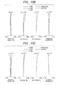
- FIG. 14A is an aberration diagram in the state in which focus is at infinity at the wide angle end according to Numerical Embodiment 7.
- FIG. 14B is an aberration diagram in the state in which focus is at infinity at an intermediate zoom position according to Numerical Embodiment 7.
- FIG. 14C is an aberration diagram in the state in which focus is at infinity at a telephoto end according to Numerical Embodiment 7.
- FIG. 15A is an optical path diagram at the wide angle end according to Numerical Embodiment 1.
- FIG. 15B is an optical path diagram at the intermediate zoom position according to Numerical Embodiment 1.
- FIG. 15C is an optical path diagram at the telephoto end according to Numerical Embodiment 1.
- FIG. 16 is a schematic diagram of achromatism for two colors and a residual secondary spectrum of an axial chromatic aberration of a positive lens unit.
- FIG. 17 is a schematic diagram of achromatism for two colors and a residual secondary spectrum of an axial chromatic aberration of a negative lens unit.
- FIG. 18 is a schematic diagram of achromatism for two colors and a residual secondary spectrum of a lateral chromatic aberration of the positive lens unit.
- FIG. 19 is a schematic diagram of achromatism for two colors and a residual secondary spectrum of a lateral chromatic aberration of the negative lens unit.
- FIG. 20 is a schematic diagram illustrating a main part of an image pickup apparatus according to the present invention.
- the zoom lens of the present invention has a feature in defining a ratio of focal lengths of the first lens unit and the second lens unit, a ratio of focal lengths of the second lens unit and the third lens unit, and a lateral magnification of the third lens unit at a wide angle end.
- the zoom lens according to the present invention includes in order from an object side a first lens unit having a positive refractive power which does not move for zooming, a second lens unit having a negative refractive power which moves during varying magnification, a third lens unit having a positive refractive power which moves during varying magnification, and a fourth lens unit having a positive refractive power which does not move for varying magnification.
- the zoom lens satisfies the following relationships: ⁇ 3.2 ⁇ f 1 /f 2 ⁇ 1.0 (1); ⁇ 0.55 ⁇ f 2 /f 3 ⁇ 0.20 (2); and ⁇ 0.7 ⁇ 1/ ⁇ 3 w ⁇ 0.5 (3), where f1 is a focal length of the first lens unit, f2 is a focal length of the second lens unit, f3 is a focal length of the third lens unit, and ⁇ 3w is the lateral magnification of the third lens unit at the wide angle end when a ray enters from infinity.
- An optical effect obtained by including the first lens unit having a positive refractive power which does not move for zooming, the second lens unit having a negative refractive power which moves during varying magnification, the third lens unit having a positive refractive power which moves during varying magnification, and the fourth lens unit having a positive refractive power which does not move for varying magnification according the present invention is described.
- FIGS. 15A , 15 B, and 15 C are optical path diagrams at the wide angle end, an intermediate zoom position, and a telephoto end according to Embodiment 1 of the present invention, respectively.
- the first to fourth lens units are denoted by U 1 to U 4 , respectively.
- a lens unit on the image side of the first lens unit has a lens diameter determined by an off-axial ray at the telephoto end
- a lens on the object side of the second lens unit has a lens diameter determined by an off-axial ray at the wide angle end.
- it is effective to suppress the lens diameters of the first lens unit and the second lens unit, which have heavy lens weights.
- the refractive power of the third lens unit is positive as in the present invention, a ray height of the off-axial ray may be reduced, with the result that a lens configuration that is effective in reducing the size and weight may be obtained.
- Expression (1) defines a ratio of the focal length of the first lens unit to the focal length of the second lens unit.
- Expression (1) is satisfied, both the wide angle of field of the zoom lens and the correction of an aberration variation may be achieved.
- a focal length of the zoom lens takes a value obtained by multiplying the focal length of the first lens unit by lateral magnifications of the second to fourth lens units, and hence in order to achieve the wide angle of field, the focal length of the first lens unit needs to be set appropriately.
- the condition of the upper limit of Expression (1) is not satisfied, the refractive power of the first lens unit becomes stronger, which makes it difficult to correct the aberration variation.
- the refractive power of the second lens unit becomes insufficient with respect to the first lens unit, which is disadvantageous in reducing size and weight of the zoom lens.
- the refractive power of the first lens unit becomes insufficient, which makes it difficult to increase the angle of field and reduce the size and weight. It is further preferred to set Expression (1) as follows: ⁇ 3.0 ⁇ f 1 /f 2 ⁇ 1.5 (1a).
- Expression (2) defines a ratio of the focal length of the second lens unit and the focal length of the third lens unit.
- the focal length of the second lens unit with respect to the third lens unit may be appropriately set, and hence it is possible to efficiently realize not only both the wide angle of field and the reduced size and weight, but also a high zoom ratio and high optical performance.
- the condition of the upper limit of Expression (2) is not satisfied, the refractive power of the second lens unit becomes strong, and hence the aberration variation accompanying the magnification varying becomes large, which makes it difficult to achieve good optical performance over the entire zoom range.
- the refractive power of the third lens unit becomes weak, and hence the above-mentioned effect of suppressing the lens diameter on the image side of the first lens unit and the lens diameter on the object side of the second lens unit becomes weak, which is disadvantageous in reducing the size and weight.
- the refractive power of the second lens unit becomes weak, and hence a moving amount of the second lens unit accompanying the varying magnification becomes large, which makes it difficult to achieve both the high zoom ratio and the reduced size and weight. It is further preferred to set Expression (2) as follows: ⁇ 0.45 ⁇ f 2 /f 3 ⁇ 0.25 (2a).
- Expression (3) defines a reciprocal of the lateral magnification ⁇ 3w of the third lens unit at the wide angle end when a ray enters from infinity.
- Expression (3) is defined to reduce the size and weight of the entire lens system.
- the ray that exits the third lens unit becomes substantially afocal, and hence the number of constituent lenses of the fourth lens unit may be reduced, which is advantageous in reducing the size and weight.
- the condition of the upper limit of Expression (3) is not satisfied, the ray that exits the third lens unit becomes more divergent, and hence a lens unit having a strong positive refractive power is required for the fourth lens unit, which increases the number of constituent lenses of the fourth lens unit.
- the first lens unit includes a first sub-lens unit having a negative refractive power that is fixed and does not move for focusing, a second sub-lens unit having a positive refractive power that moves to the image side for focusing from the infinity side to the proximity side, and a third sub-lens unit having a positive refractive power that does not move for focusing.
- the arrangements of the first lens unit with a lens unit having a negative refractive power on the object side of the first lens unit and a lens unit having a positive refractive power on the image side of the first lens unit facilitate setting an image side principal point of the first lens unit on the image side, resulting in a configuration that is advantageous in increasing the angle of field.
- a ratio of a focal length of the second sub-lens unit to a focal length of the first sub-lens unit and a ratio of a focal length of the third sub-lens unit to the focal length of the first lens unit are defined.
- the first lens unit satisfies the following relationship: ⁇ 2.3 ⁇ f 12 /f 11 ⁇ 1.5 (4), where f11 is the focal length of the first sub-lens unit and f12 is the focal length of the second sub-lens unit.
- Expression (4) is defined to suppress the moving amount of the second sub-lens unit in focusing and to increase the optical performance.
- Expression (4) is especially effective for the zoom lens having a short distance to the closest object (for example, when a focal length at the telephoto end and the distance to the closest object are expressed in mm, a ratio of the minimum object distance to the focal length of the telephoto end is smaller than 10).
- the condition of the upper limit of Expression (4) is not satisfied, the refractive power of the first sub-lens unit becomes weak, and hence the moving amount of the second sub-lens unit for focusing becomes large, which is disadvantageous in reducing the size and weight of the zoom lens.
- the first lens unit satisfies the following relationship: 0.9 ⁇ f 13 /f 1 ⁇ 1.5 (5), where f13 is the focal length of the third sub-lens unit.
- Expression (5) is defined to reduce the size and weight and to increase the performance.
- the refractive power of the third sub-lens unit becomes weak, which makes it difficult to suppress the diameters of the first sub-lens unit and the second sub-lens unit. This results in a disadvantage in reducing the size and weight of the zoom lens.
- a configuration of the first sub-lens unit and dispersion of an optical material used in the first sub-lens unit are defined.
- the first sub-lens unit includes at least one convex lens and at least one concave lens and satisfies the following relationship: 18 ⁇ 11 n ⁇ 11 p ⁇ 45 (6), where ⁇ 11p is an average value of an Abbe constant of the convex lens constituting the first sub-lens unit, and ⁇ 11n is an average value of an Abbe constant of the concave lens.
- Expression (6) defines a condition for achieving good optical performance while suppressing a variation in chromatic aberration during focusing.
- Existing optical materials have a tendency that as an Abbe constant ⁇ d becomes larger, a refractive index becomes smaller, and when the condition of the upper limit of Expression (6) is not satisfied, the refractive index of the concave lens constituting the first sub-lens unit becomes lower. As a result, the curvature radii of the lenses become smaller, which makes it difficult to correct the high-order aberrations.
- a shape of a lens closest to the object of the first sub-lens unit is defined.
- the lens closest to the object of the first sub-lens unit is a concave lens and satisfies the following relationship: ⁇ 0.5 ⁇ ( R 1 +R 2)/( R 1 ⁇ R 2) ⁇ 2.5 (7), where R1 is a curvature radius of a surface on the object side, and R2 is a curvature radius of a surface on the image side.
- Expression (7) defines an increase in angle of field and off-axial aberration at the wide angle end for successfully correcting the distortion in particular.
- an aberration coefficient V of the distortion is proportional to the first power of an axial paraxial chief ray height H and to the third power of a paraxial chief ray height H′.
- the paraxial chief ray height at the wide angle end is high for the lens closest to the object of the first sub-lens unit, and in order to successfully correct the distortion at the wide angle end, the shape of a lens G 1 closest to the object of the first sub-lens unit needs to be set appropriately.
- a surface on the object side and a surface on the image side of the lens G 1 are defined here as an r1 surface and an r2 surface, respectively.
- the lens G 1 has a meniscus shape in which the r1 surface is a convex surface and the r2 surface is a concave surface, and further the difference of the curvature radii of the r1 surface and the r2 surface becomes smaller, and hence the negative refractive power of the lens becomes weaker.
- the r1 surface is the concave surface and the curvature radius becomes even smaller, which makes it difficult to correct the barrel distortion at the wide angle end. It is further preferred to set Expression (7) as follows: 0.5 ⁇ ( R 1 +R 2)/( R 1 ⁇ R 2) ⁇ 2.0 (7a).
- a configuration of the third sub-lens unit and a partial dispersion ratio of an optical material used in the third sub-lens unit are defined.
- the third sub-lens unit includes at least two convex lenses and at least one concave lens and satisfies the following conditional expression: ⁇ 2.5 ⁇ 10 ⁇ 3 ⁇ ( ⁇ 13 p ⁇ 13 n )/( ⁇ 13 p ⁇ 13 n ) ⁇ 5.0 ⁇ 10 ⁇ 4 (8), where ⁇ 13p and ⁇ 13p are average values of Abbe constants and partial dispersion ratios of the convex lenses constituting the third sub-lens unit, respectively, and ⁇ 13n and ⁇ 13n are average values of an Abbe constant and a partial dispersion ratio of the concave lens, respectively.
- the Abbe constant and the partial dispersion ratio of a material of an optical device (lens) used in the present invention are defined as follows. Refractive indices with respect to g-line (435.8 nm), F-line (486.1 nm), d-line (587.6 nm), and C-line (656.3 nm) of Fraunhofer line are denoted by Ng, NF, Nd, and NC, respectively.
- the partial dispersion ratio ⁇ gF of an existing optical material is present in a narrow range with respect to the Abbe constant ⁇ d. Further, the existing optical material has a tendency that, as the Abbe constant ⁇ d becomes smaller, the partial dispersion ratio ⁇ gF becomes larger.
- FIG. 16 is a schematic diagram of achromatism for two colors and a residual secondary spectrum of an axial chromatic aberration of a lens unit having a positive refractive power LP.
- a material having a large Abbe constant ⁇ 1 is used for a positive lens 1
- a material having a small Abbe constant ⁇ 2 is used for a negative lens 2 . Therefore, the positive lens 1 has a small partial dispersion ratio ⁇ 1 and the negative lens 2 has a large partial dispersion ratio ⁇ 2, and when the axial chromatic aberration is corrected for the C-line and the F-line, an imaging point of the g-line deviates to the image side.
- ⁇ S ⁇ (1/ ⁇ ( ⁇ 1 ⁇ 2)/( ⁇ 1 ⁇ 2) (vii).
- the negative lens 1 has a small partial dispersion ratio ⁇ 1
- the positive lens 2 has a large partial dispersion ratio ⁇ 2.
- the imaging point of the g-line deviates to the object side.
- the third sub-lens unit and the second lens unit in which the secondary spectrum occurs significantly, need to be adjusted for the amount of occurrence.
- the third sub-lens unit has a positive refractive power, and in order to successfully correct the secondary spectrum of the axial chromatic aberration at the telephoto end, such glass material as to reduce the secondary spectrum amount ⁇ S that occurs in the third sub-lens unit needs to be selected.
- the second lens unit has a negative refractive power, and such glass material as to increase the secondary spectrum amount ⁇ S in the second lens unit may be selected to successfully correct the secondary spectrum of the axial chromatic aberration that occurs in the first lens unit.
- FIG. 18 is a schematic diagram of the achromatism for two colors and the residual secondary spectrum of a lateral chromatic aberration of the lens unit LP having a positive refractive power, which is located between the object surface and the stop.
- a material having a large Abbe constant ⁇ 1 is used for the positive lens 1
- a material having a small Abbe constant ⁇ 2 is used for the negative lens 2 . Therefore, the positive lens 1 has a small partial dispersion ratio ⁇ 1 and the negative lens 2 has a large partial dispersion ratio ⁇ 2, and when the lateral chromatic aberration is corrected for the C-line and the F-line, the imaging point of the g-line deviates toward an optical axis.
- the negative lens 1 has a small partial dispersion ratio ⁇ 1
- the positive lens 2 has a large partial dispersion ratio ⁇ 2.
- the imaging point of the g-line deviates away from the optical axis.
- the amounts of occurrence need to be adjusted for the third sub-lens unit and the second lens unit.
- the third sub-lens unit has a positive refractive power, and in order to successfully correct the secondary spectrum of the lateral chromatic aberration at the wide angle end, such glass material as to increase the secondary spectrum amount ⁇ Y that occurs in the third sub-lens unit needs to be selected.
- the second lens unit has a negative refractive power, and such glass material as to reduce the secondary spectrum amount ⁇ Y that occurs in the second lens unit needs to be selected.
- the condition of Expression (8) is defined to successfully correct the lateral chromatic aberration at the wide angle end and the axial chromatic aberration at the telephoto end.
- the condition of the upper limit of Expression (8) is not satisfied, which is advantageous in correcting the secondary spectrum of the axial chromatic aberration at the telephoto end, the secondary spectrum of the lateral chromatic aberration at the wide angle end is increased, which makes it difficult to achieve high optical performance over the entire zoom range.
- Expression (8) As follows: ⁇ 2.0 ⁇ 10 ⁇ 3 ⁇ ( ⁇ 13 p ⁇ 13 n )/( ⁇ 13 p ⁇ 13 n ) ⁇ 1.0 ⁇ 10 ⁇ 3 (8a).
- a configuration of the second lens unit and a partial dispersion ratio of an optical material used in the second lens unit are defined.
- the second lens unit includes at least one convex lens and at least two concave lenses and satisfies the following relationship: ⁇ 3.5 ⁇ 10 ⁇ 3 ⁇ ( ⁇ 2 p ⁇ 2 n )/( ⁇ 2 p ⁇ 2 n ) ⁇ 1.5 ⁇ 10 ⁇ 3 (9), where ⁇ 2p and ⁇ 2p are average values of an Abbe constant and a partial dispersion ratio of the convex lens constituting the second lens unit, respectively, and ⁇ 2n and ⁇ 2n are average values of Abbe constants and partial dispersion ratios of the concave lenses, respectively.
- This condition is defined to successfully correct the lateral chromatic aberration at the wide angle end and the axial chromatic aberration at the telephoto end.
- the condition of the upper limit of Expression (9) is not satisfied, which is advantageous in correcting the secondary spectrum of the lateral chromatic aberration at the wide angle end, the secondary spectrum of the axial chromatic aberration at the telephoto end is increased, which makes it difficult to achieve high optical performance over the entire zoom range.
- the condition of the lower limit of Expression (9) which is advantageous in correcting the secondary spectrum of the axial chromatic aberration at the telephoto end, the secondary spectrum of the lateral chromatic aberration at the wide angle end is increased, which makes it difficult to achieve high optical performance over the entire zoom range.
- Expression (9) is further preferred to set Expression (9) as follows: ⁇ 3.0 ⁇ 10 ⁇ 3 ⁇ ( ⁇ 2 p ⁇ 2 n )/( ⁇ 2 p ⁇ 2 n ) ⁇ 2.0 ⁇ 10 ⁇ 3 (9a).
- a configuration of the first sub-lens unit for achieving a wide angle of field is defined.
- the first sub-lens unit includes one convex lens and at least two concave lenses, and the lens closest to the image of the first sub-lens unit includes a convex lens.
- the arrangements of a lens unit having a negative refractive power on the object side of the first sub-lens unit and a lens unit having a positive refractive power on the image side of the first sub-lens unit facilitate setting the image side principal point of the first lens unit on the image side, resulting in a configuration that is advantageous in increasing the angle of field.
- a ratio of a focal length of each of the convex lens and the concave lenses in the first sub-lens unit to the focal length of the first sub-lens unit is defined.
- the first sub-lens unit satisfies the following relationship: ⁇ 3.5 ⁇ f 11 p/f 11 ⁇ 1.5 (10); and 0.5 ⁇ f 11 n/f 11 ⁇ 0.8 (11), where f11p and f11n are a combined focal length of the convex lens and a combined focal length of the concave lenses in the first sub-lens unit, respectively.
- This condition is defined to achieve good optical performance in addition to the realization of both the wide angle of field and the reductions in size and weight.
- the curvature radius of the lens having a positive refractive power of the first sub-lens unit becomes smaller to increase the high-order aberrations, which makes it difficult to achieve high optical performance.
- the condition of the lower limit of Expression (10) is not satisfied, the positive refractive power of the first sub-lens unit becomes weaker, with the result that the negative refractive power of the first sub-lens unit also becomes weaker, which makes it difficult to obtain the effect of an enough increase in angle of field.
- Expression (11) it is further preferred to set Expression (11) as follows: 0.60 ⁇ f 11 n/f 11 ⁇ 0.75 (11a).
- an image pickup apparatus of the present invention has a feature in including the zoom lens of each of the embodiments and a solid-state image pick-up element having a predetermined effective image pick-up range for receiving an image formed by the zoom lens.
- a specific configuration of the zoom lens of the present invention is described below by way of features of lens configurations of Numerical Embodiments 1 to 7 corresponding to Embodiments 1 to 7, respectively.
- FIG. 1 is a lens cross-sectional view when focused on infinity at the wide angle end in the zoom lens according to Embodiment 1 (Numerical Embodiment 1) of the present invention.
- FIGS. 2A , 2 B, and 2 C are longitudinal aberration diagrams of the wide angle end of Numerical Embodiment 1, the focal length of 40 mm of Numerical Embodiment 1, and the telephoto end of Numerical Embodiment 1, respectively.
- Each of the aberration diagrams is a longitudinal aberration diagram when focused on infinity.
- the value of the focal length is a value obtained by expressing numerical embodiments, which are to be described below, in mm. This applies to all the numerical embodiments below.
- the zoom lens includes in order from the object side a first lens unit (focus lens unit) U 1 having a positive refractive power for focusing.
- the zoom lens further includes a second lens unit (variator) U 2 having a negative refractive power for varying magnification which moves to the image side for varying magnification from the wide angle end to the telephoto end.
- the zoom lens further includes a third lens unit (compensator) U 3 having a positive refractive power which moves on the optical axis nonlinearly in conjunction with the movement of the second lens unit U 2 and corrects an image plane variation accompanying the magnification varying.
- the zoom lens further includes a fourth lens unit (relay lens unit) U 4 having a positive refractive power and an imaging function which does not move for varying magnification.
- the second lens unit U 2 and the third lens unit U 3 constitute a magnification-varying system.
- An aperture stop SP is arranged on the object side of the fourth lens unit U 4 .
- an image plane I corresponds to an image pickup surface of a solid-state image pick-up element (photoelectric conversion element) or the like for receiving an image formed by the zoom lens and converting light to electricity.
- the image plane I corresponds to a film surface on which the image formed by the zoom lens is exposed.
- spherical aberrations are illustrated with respect to e-line, g-line, and C-line by a solid line, a one-dot chain line, and a dotted line, respectively. Further, astigmatisms are illustrated on a meridional image plane by a dotted line and on a sagittal image plane by a solid line. In addition, lateral chromatic aberrations are illustrated with respect to g-line and C-line by a one-dot chain line and a dotted line, respectively. A half angle of field is denoted by ⁇ and an F-number is denoted by Fno.
- each of the wide angle end and the telephoto end refers to a zooming position obtained when the second lens unit U 2 for magnification-varying is positioned at each of the ends of a range in which the second lens unit U 2 may mechanically move along the optical axis.
- the first lens unit U 1 corresponds to first to seventeenth surfaces.
- the first lens unit U 1 includes a first sub-lens unit U 1 a having a negative refractive power which does not move for focusing, a second sub-lens unit U 1 b having a positive refractive power which moves to the image side when focusing from the infinity side to the proximity side, and a third sub-lens unit U 1 c having a positive refractive power which does not move for focusing.
- the first sub-lens unit U 1 a includes in order from the object side a meniscus concave lens G 1 having a convex surface facing to the object side, a biconcave lens G 2 , a meniscus concave lens G 3 having a convex surface facing toward the image side, and a meniscus convex lens G 4 having a concave surface facing toward the image side.
- the second sub-lens unit U 1 b includes a biconvex lens G 5 .
- the third sub-lens unit U 1 c includes a cemented lens obtained by cementing a meniscus concave lens G 6 having a convex surface facing toward the object side and a meniscus convex lens G 7 having a concave surface facing toward the image side, a biconvex lens G 8 , and a meniscus convex lens G 9 having a concave surface facing toward the image side.
- the second lens unit U 2 includes a meniscus concave lens having a convex surface facing toward the object side, a cemented lens of a biconcave lens and a meniscus convex lens having a concave surface facing toward the image side, and a meniscus concave lens having a convex surface facing toward the image side.
- the third lens unit U 3 includes a convex lens and a concave lens and is constituted of a total of three lenses.
- the fourth lens unit U 4 includes a convex lens and a concave lens and is constituted of a total of six lenses.
- Numerical Embodiment 1 which corresponds to the above-mentioned Embodiment 1 is described. Not only in Numerical Embodiment 1 but in all numerical embodiments, “i” denotes an order of a surface (optical surface) from the object side, “ri” denotes a curvature radius of an i-th surface from the object side, and “di” denotes an interval (on the optical axis) between the i-th surface and the (i+1)th surface from the object side.
- ndi refractive index
- ⁇ di Abbe constant
- ⁇ gFi partial dispersion ratio of a medium (optical member) between the i-th surface and the (i+1)th surface.
- the aspherical shape is expressed in the following expression where an X axis corresponds to the optical axis, an H axis is set perpendicularly to the optical axis, a traveling direction of light corresponds to a positive direction, “R” denotes a paraxial curvature radius, “k” denotes a conic coefficient, and “A4”, “A6”, “A8”, “A10”, and “A12” each denote an aspherical coefficient. Further, “e-Z” denotes “ ⁇ 10 ⁇ Z ”.
- the axial paraxial chief ray height H at each optical surface (lens surface), an angle ⁇ formed by the axial paraxial chief ray and the optical axis, the paraxial chief ray height H′, and an angle ⁇ ′ formed by the paraxial chief ray and the optical axis when focused on an object at infinity at the wide angle end of this embodiment are also described in the numerical embodiments. Further, contribution values at each surface of the aberration coefficient V of the third-order distortion when focused on the object at infinity at the wide angle end of this embodiment are described.
- the axial paraxial chief ray refers to, when the focal length at the wide angle end of the entire optical system is normalized to 1, a paraxial ray that is caused to enter the optical system in parallel to the optical axis with an incident height of 1 (of rays that enter positions in the vicinity of the optical axis of the surface closest to the object in a state of being parallel to the optical axis, a ray that passes through the optical axis at the image plane position).
- tables of the numerical embodiments show the height of the axial paraxial chief ray (distance from the optical axis) on each optical surface and an incident angle on each optical surface.
- the paraxial chief ray is, of rays that enter a maximum image height of the image plane (receiving surface of the image pickup element) when the focal length at the wide angle end of the entire optical system is normalized to 1, a paraxial ray that passes through an intersection of an incident pupil and the optical axis of the optical system.
- the tables of the numerical embodiments show a height of the paraxial chief ray (distance from the optical axis) on each optical surface and the incident angle on each optical surface.
- Expressions (1) to (11) are satisfied, and with a high zoom ratio of 2.60 ⁇ , a wide angle of field is achieved as an image pick-up field angle (angle of field) of 63.76° at the wide angle end.
- the aberration coefficient (aberration coefficient of the third-order distortion) V of one surface having the highest paraxial chief ray height is set in an appropriate range, to thereby effectively correct the barrel distortion at the wide angle end. It is preferred that the value Vdis of the aberration coefficient V of the third-order distortion at the surface (lens surface) having the highest paraxial chief ray height satisfy: ⁇ 0.5 ⁇ V dis ⁇ 1.5 (12).
- the zoom lens having high optical performance in which the aberrations are successfully corrected over the entire zoom range is achieved.
- the zoom lens of the present invention it is essential that the zoom lens of the present invention satisfy Expressions (1), (2), and (3), but the zoom lens does not necessarily satisfy Expressions (4) to (12).
- Expressions (4) to (12) when even at least one of Expressions (4) to (12) is satisfied, better effects may be provided. This is also true for the other embodiments.
- FIG. 20 is a schematic diagram illustrating an image pickup apparatus (television camera system) having the zoom lens according to each embodiment as an image pickup optical system.
- an image pickup apparatus 125 includes a zoom lens 101 , which is any one of the zoom lenses according to Embodiments 1 to 7.
- the zoom lens 101 may be detachably mounted on a camera body 124 , to thereby constitute the image pickup apparatus 125 .
- the zoom lens 101 includes a first lens unit F, a magnification varying unit LZ, and a fourth lens unit for imaging R.
- the first lens unit F includes a focusing lens unit.
- the magnification varying unit LZ includes a second lens unit which moves along the optical axis to vary magnification.
- the magnification varying unit LZ includes a third lens unit which moves along the optical axis to correct an image plane variation due to magnification varying.
- the zoom lens 101 includes an aperture stop SP.
- the zoom lens 101 includes driving mechanisms 114 and 115 , such as a helicoid or a cam, which drives the first lens unit F and the magnification varying unit LZ, respectively, along the optical axis.
- the image pickup apparatus 125 includes motors (driving units) 116 to 118 , which electrically drive the driving mechanisms 114 and 115 and the aperture stop SP, respectively.
- Detectors 119 to 121 are configured to detect the position of the first lens unit F, the position of the magnification varying unit LZ on the optical axis, and the aperture diameter of the aperture stop SP.
- the camera body 124 includes a glass block 109 , which is equivalent to an optical filter or a color separation optical system provided within the camera body 124 .
- the camera body 124 includes a solid state image pickup element (photoelectrical conversion element) 110 , such as a charge-coupled device (CCD) sensor or a complementary metal-oxide semiconductor (CMOS) sensor.
- the solid state image pickup element 110 is configured to receive an object image formed by the zoom lens 101 .
- central processing units (CPUs) 111 and 122 control the driving of the camera body 124 and the zoom lens 101 , respectively.
- an image pickup apparatus having high optical performance may be implemented.
- FIG. 3 is a lens cross-sectional view when focused on infinity at the wide angle end in the zoom lens according to Embodiment 2 (Numerical Embodiment 2) of the present invention.
- FIGS. 4A , 4 B, and 4 C are longitudinal aberration diagrams of the wide angle end of Numerical Embodiment 2, the focal length of 50 mm of Numerical Embodiment 2, and the telephoto end of Numerical Embodiment 2, respectively.
- Each of the aberration diagrams is a longitudinal aberration diagram when focused on infinity.
- the zoom lens includes in order from the object side a first lens unit (focus lens unit) U 1 having a positive refractive power for focusing.
- the zoom lens further includes a second lens unit (variator) U 2 having a negative refractive power for varying magnification which moves to the image side for varying magnification from the wide angle end to the telephoto end.
- the zoom lens further includes a third lens unit (compensator) U 3 having a positive refractive power which moves on the optical axis nonlinearly in conjunction with the movement of the second lens unit U 2 and corrects an image plane variation accompanying the magnification varying.
- the zoom lens further includes a fourth lens unit (relay lens unit) U 4 having a positive refractive power and an imaging function which does not move for varying magnification.
- the first lens unit U 1 corresponds to first to fifteenth surfaces.
- the first lens unit U 1 includes a first sub-lens unit U 1 a having a negative refractive power which does not move for focusing, a second sub-lens unit U 1 b having a positive refractive power which moves to the image side when focusing from the infinity side to the proximity side, and a third sub-lens unit U 1 c having a positive refractive power which does not move for focusing.
- the first sub-lens unit U 1 a includes in order from the object side a meniscus concave lens G 1 having a convex surface facing toward the object side, a biconcave lens G 2 , and a biconvex lens G 3 .
- the second sub-lens unit U 1 b includes a biconvex lens G 4 .
- the third sub-lens unit U 1 c includes a cemented lens obtained by cementing a meniscus concave lens G 5 having a convex surface facing toward the object side and a biconvex lens G 6 , a biconvex lens G 7 , and a meniscus convex lens G 8 having a concave surface facing toward the image side.
- the second lens unit U 2 includes a meniscus concave lens having a convex surface facing toward the object side, a biconcave lens, a meniscus convex lens having a concave surface facing toward the image side, and a biconcave lens.
- the third lens unit U 3 includes a convex lens and a concave lens and is constituted of a total of three lenses.
- the fourth lens unit U 4 includes a convex lens and a concave lens and is constituted of a total of six lenses.
- Expressions (1) to (11) are satisfied, and with a high zoom ratio of 2.67 ⁇ , a wide angle of field is achieved as an image pick-up field angle (angle of field) of 54.80° at the wide angle end. Moreover, the aberration coefficient V of the one surface having the highest paraxial chief ray height is set in an appropriate range to effectively correct the barrel distortion at the wide angle end. In addition, the zoom lens having high optical performance in which the aberrations are successfully corrected over the entire zoom range is achieved.
- FIG. 5 is a lens cross-sectional view when focused on infinity at the wide angle end in the zoom lens according to Embodiment 3 (Numerical Embodiment 3) of the present invention.
- FIGS. 6A , 6 B, and 6 C are longitudinal aberration diagrams of the wide angle end of Numerical Embodiment 3, the focal length of 70 mm of Numerical Embodiment 3, and the telephoto end of Numerical Embodiment 3, respectively.
- Each of the aberration diagrams is a longitudinal aberration diagram when focused on infinity.
- the zoom lens includes in order from the object side a first lens unit (focus lens unit) U 1 having a positive refractive power for focusing.
- the zoom lens further includes a second lens unit (variator) U 2 having a negative refractive power for varying magnification which moves to the image side for varying magnification from the wide angle end to the telephoto end.
- the zoom lens further includes a third lens unit (compensator) U 3 having a positive refractive power which moves on the optical axis nonlinearly in conjunction with the movement of the second lens unit U 2 and corrects an image plane variation accompanying the magnification varying.
- the zoom lens further includes a fourth lens unit (relay lens unit) U 4 having a positive refractive power and an imaging function which does not move for varying magnification.
- the first lens unit U 1 corresponds to first to seventeenth surfaces.
- the first lens unit U 1 includes a first sub-lens unit U 1 a having a negative refractive power which does not move for focusing, a second sub-lens unit U 1 b having a positive refractive power which moves to the image side when focusing from the infinity side to the proximity side, and a third sub-lens unit U 1 c having a positive refractive power which does not move for focusing.
- the first sub-lens unit U 1 a includes in order from the object side a cemented lens of a biconcave lens G 1 and a meniscus convex lens G 2 having a concave surface facing toward the image side, and a biconcave lens G 3 .
- the second sub-lens unit U 1 b includes a cemented lens of a meniscus concave lens G 4 having a convex surface facing toward the object side and a biconvex lens G 5 .
- the third sub-lens unit U 1 c includes a meniscus concave lens G 6 having a convex surface facing toward the object side, a biconvex lens G 7 , a biconvex lens G 8 , and a meniscus convex lens G 9 having a concave surface facing toward the image side.
- the second lens unit U 2 includes a meniscus concave lens having a convex surface facing toward the object side, a biconcave lens, a biconvex lens, and a biconcave lens.
- the third lens unit U 3 includes a convex lens and a concave lens and is constituted of a total of three lenses.
- the fourth lens unit U 4 includes a convex lens and a concave lens and is constituted of a total of six lenses.
- Expressions (1) to (9) are satisfied, and with a high zoom ratio of 3.00 ⁇ , a wide angle of field is achieved as an image pick-up field angle (angle of field) of 42.48° at the wide angle end.
- the aberration coefficient V of the one surface having the highest paraxial chief ray height is set in an appropriate range to effectively correct the barrel distortion at the wide angle end.
- the zoom lens having high optical performance in which the aberrations are successfully corrected over the entire zoom range is achieved.
- FIG. 7 is a lens cross-sectional view when focused on infinity at the wide angle end in the zoom lens according to Embodiment 4 (Numerical Embodiment 4) of the present invention.
- FIGS. 8A , 8 B, and 8 C are longitudinal aberration diagrams of the wide angle end of Numerical Embodiment 4, the focal length of 80 mm of Numerical Embodiment 4, and the telephoto end of Numerical Embodiment 4, respectively.
- Each of the aberration diagrams is a longitudinal aberration diagram when focused on infinity.
- the zoom lens includes in order from the object side a first lens unit (focus lens unit) U 1 having a positive refractive power for focusing.
- the zoom lens further includes a second lens unit (variator) U 2 having a negative refractive power for varying magnification which moves to the image side for varying magnification from the wide angle end to the telephoto end.
- the zoom lens further includes a third lens unit (compensator) U 3 having a positive refractive power which moves on the optical axis nonlinearly in conjunction with the movement of the second lens unit U 2 and corrects an image plane variation accompanying the magnification varying.
- the zoom lens further includes a fourth lens unit (relay lens unit) U 4 having a positive refractive power and an imaging function which does not move for varying magnification.
- the first lens unit U 1 corresponds to first to seventeenth surfaces.
- the first lens unit U 1 includes a first sub-lens unit U 1 a having a negative refractive power which does not move for focusing, a second sub-lens unit U 1 b having a positive refractive power which moves to the image side when focusing from the infinity side to the proximity side, and a third sub-lens unit U 1 c having a positive refractive power which does not move for focusing.
- the first sub-lens unit U 1 a includes in order from the object side a biconcave lens G 1 , a meniscus convex lens G 2 having a concave surface facing toward the image side, and a biconcave lens G 3 .
- the second sub-lens unit U 1 b includes a cemented lens of a biconvex lens G 4 and a meniscus concave lens G 5 having a convex surface facing toward the image side.
- the third sub-lens unit U 1 c includes a meniscus concave lens G 6 having a convex surface facing toward the object side, a biconvex lens G 7 , a meniscus convex lens G 8 having a concave surface facing toward the image side, and a meniscus convex lens G 9 having a concave surface facing toward the image side.
- the second lens unit U 2 includes a meniscus concave lens having a convex surface facing toward the object side, a biconcave lens, a biconvex lens, and a biconcave lens.
- the third lens unit U 3 includes a convex lens and a concave lens and is constituted of a total of three lenses.
- the fourth lens unit U 4 includes a convex lens and a concave lens and is constituted of a total of six lenses.
- Expressions (1) to (9) are satisfied, and with a high zoom ratio of 3.11 ⁇ , a wide angle of field is achieved as an image pick-up field angle (angle of field) of 38.12° at the wide angle end.
- the aberration coefficient V of the one surface having the highest paraxial chief ray height is set in an appropriate range to effectively correct the barrel distortion at the wide angle end.
- the zoom lens having high optical performance in which the aberrations are successfully corrected over the entire zoom range is achieved.
- FIG. 9 is a lens cross-sectional view when focused on infinity at the wide angle end in the zoom lens according to Embodiment 5 (Numerical Embodiment 5) of the present invention.
- FIGS. 10A , 10 B, and 10 C are longitudinal aberration diagrams of the wide angle end of Numerical Embodiment 5, the focal length of 70 mm of Numerical Embodiment 5, and the telephoto end of Numerical Embodiment 5, respectively.
- Each of the aberration diagrams is a longitudinal aberration diagram when focused on infinity.
- the zoom lens includes in order from the object side a first lens unit (focus lens unit) U 1 having a positive refractive power for focusing.
- the zoom lens further includes a second lens unit (variator) U 2 having a negative refractive power for varying magnification which moves to the image side for varying magnification from the wide angle end to the telephoto end.
- the zoom lens further includes a third lens unit (compensator) U 3 having a positive refractive power which moves on the optical axis nonlinearly in conjunction with the movement of the second lens unit U 2 and corrects an image plane variation accompanying the magnification varying.
- the zoom lens further includes a fourth lens unit (relay lens unit) U 4 having a positive refractive power and an imaging function which does not move for varying magnification.
- the first lens unit U 1 corresponds to first to fourteenth surfaces.
- the first lens unit U 1 includes a first sub-lens unit U 1 a having a negative refractive power which does not move for focusing, a second sub-lens unit U 1 b having a positive refractive power which moves to the image side when focusing from the infinity side to the proximity side, and a third sub-lens unit U 1 c having a positive refractive power which does not move for focusing.
- the first sub-lens unit U 1 a includes in order from the object side a meniscus concave lens G 1 having a convex surface facing toward the object side, a meniscus concave lens G 2 having a convex surface facing toward the image side, and a meniscus convex lens G 3 having a concave surface facing toward the image side.
- the second sub-lens unit U 1 b includes a meniscus concave lens G 4 having a convex surface facing toward the object side and a biconvex lens G 5 .
- the third sub-lens unit U 1 c includes a cemented lens obtained by cementing a meniscus concave lens G 6 having a convex surface facing toward the object side and a biconvex lens G 7 , and a meniscus convex lens G 8 having a concave surface facing toward the image side.
- the second lens unit U 2 includes a meniscus concave lens having a convex surface facing toward the object side, a cemented lens of a biconcave lens and a meniscus convex lens having a concave surface facing toward the image side, and a biconcave lens.
- the twenty-first surface has an aspherical surface shape. The twenty-first surface mainly corrects the field curvature on the wide angle side.
- the third lens unit U 3 includes a convex lens and a concave lens and is constituted of a total of three lenses.
- the fourth lens unit U 4 includes a convex lens and a concave lens and is constituted of a total of six lenses.
- Expressions (1) to (11) are satisfied, and with a high zoom ratio of 5.00 ⁇ , a wide angle of field is achieved as an image pick-up field angle (angle of field) of 54.80° at the wide angle end.
- the aberration coefficient V of the one surface having the highest paraxial chief ray height is set in an appropriate range to effectively correct the barrel distortion at the wide angle end.
- the zoom lens having high optical performance in which the aberrations are successfully corrected over the entire zoom range is achieved.
- FIG. 11 is a lens cross-sectional view when focused on infinity at the wide angle end in the zoom lens according to Embodiment 6 (Numerical Embodiment 6) of the present invention.
- FIGS. 12A , 12 B, and 12 C are longitudinal aberration diagrams of the wide angle end of Numerical Embodiment 6, the focal length of 60 mm of Numerical Embodiment 6, and the telephoto end of Numerical Embodiment 6, respectively.
- Each of the aberration diagrams is a longitudinal aberration diagram when focused on infinity.
- the zoom lens includes in order from the object side a first lens unit (focus lens unit) U 1 having a positive refractive power for focusing.
- the zoom lens further includes a second lens unit (variator) U 2 having a negative refractive power for varying magnification which moves to the image side for varying magnification from the wide angle end to the telephoto end.
- the zoom lens further includes a third lens unit (compensator) U 3 having a positive refractive power which moves on the optical axis nonlinearly in conjunction with the movement of the second lens unit U 2 and corrects an image plane variation accompanying the magnification varying.
- the zoom lens further includes a fourth lens unit (relay lens unit) U 4 having a positive refractive power and an imaging function which does not move for varying magnification.
- the first lens unit U 1 corresponds to first to thirteenth surfaces.
- the first lens unit U 1 includes a first sub-lens unit U 1 a having a negative refractive power which does not move for focusing, a second sub-lens unit U 1 b having a positive refractive power which moves to the image side when focusing from the infinity side to the proximity side, and a third sub-lens unit U 1 c having a positive refractive power which does not move for focusing.
- the first sub-lens unit U 1 a includes in order from the object side a biconcave lens G 1 , a meniscus concave lens G 2 having a convex surface facing toward the image side, and a meniscus convex lens G 3 having a concave surface facing toward the image side.
- the second sub-lens unit U 1 b includes a biconvex lens G 4 .
- the third sub-lens unit U 1 c includes a cemented lens obtained by cementing a meniscus concave lens G 5 having a convex surface facing toward the object side and a biconvex lens G 6 , and a meniscus convex lens G 7 having a concave surface facing toward the image side.
- the second lens unit U 2 includes a meniscus concave lens having a convex surface facing toward the object side, a biconcave lens, a meniscus convex lens having a concave surface facing toward the image side, and a biconcave lens.
- the third lens unit U 3 includes a convex lens and a concave lens and is constituted of a total of three lenses.
- the fourth lens unit U 4 includes a convex lens and a concave lens and is constituted of a total of six lenses.
- Expressions (1) to (11) are satisfied, and with a high zoom ratio of 2.86 ⁇ , a wide angle of field is achieved as an image pick-up field angle (angle of field) of 47.90° at the wide angle end. Moreover, the aberration coefficient V of the one surface having the highest paraxial chief ray height is set in an appropriate range to effectively correct the barrel distortion at the wide angle end. In addition, the zoom lens having high optical performance in which the aberrations are successfully corrected over the entire zoom range is achieved.
- FIG. 13 is a lens cross-sectional view when focused on infinity at the wide angle end in the zoom lens according to Embodiment 7 (Numerical Embodiment 7) of the present invention.
- FIGS. 14A , 14 B, and 14 C are longitudinal aberration diagrams of the wide angle end of Numerical Embodiment 7, the focal length of 21 mm of Numerical Embodiment 7, and the telephoto end of Numerical Embodiment 7, respectively.
- Each of the aberration diagrams is a longitudinal aberration diagram when focused on infinity.
- the zoom lens includes in order from the object side a first lens unit (focus lens unit) U 1 having a positive refractive power for focusing.
- the zoom lens further includes a second lens unit (variator) U 2 having a negative refractive power for varying magnification which moves to the image side for varying magnification from the wide angle end to the telephoto end.
- the zoom lens further includes a third lens unit (compensator) U 3 having a positive refractive power which moves on the optical axis nonlinearly in conjunction with the movement of the second lens unit U 2 and corrects an image plane variation accompanying the magnification varying.
- the zoom lens further includes a fourth lens unit (relay lens unit) U 4 having a positive refractive power and an imaging function which does not move for varying magnification.
- the first lens unit U 1 corresponds to first to seventeenth surfaces.
- the first lens unit U 1 includes a first sub-lens unit U 1 a having a negative refractive power which does not move for focusing, a second sub-lens unit U 1 b having a positive refractive power which moves to the image side when focusing from the infinity side to the proximity side, and a third sub-lens unit U 1 c having a positive refractive power which does not move for focusing.
- the first sub-lens unit U 1 a includes in order from the object side a meniscus concave lens G 1 having a convex surface facing toward the object side, a meniscus concave lens G 2 having a convex surface facing toward the object side, a meniscus concave lens G 3 having a convex surface facing toward the image side, and a meniscus convex lens G 4 having a concave surface facing toward the image side.
- the second sub-lens unit U 1 b includes a biconvex lens G 5 .
- the third sub-lens unit U 1 c includes a cemented lens obtained by cementing a biconcave lens G 6 and a biconvex lens G 7 , a biconvex lens G 8 , and a meniscus convex lens G 9 having a concave surface facing toward the image side.
- the first surface has an aspherical surface shape. The first surface mainly corrects the distortion on the wide angle side.
- the second lens unit U 2 includes a meniscus concave lens having a convex surface facing toward the object side, a cemented lens of a biconcave lens and a biconvex lens, and a meniscus concave lens having a convex surface facing toward the image side.
- the third lens unit U 3 includes a convex lens and a concave lens and is constituted of a total of three lenses.
- the fourth lens unit U 4 includes a convex lens and a concave lens and is constituted of a total of seven lenses.
- Expressions (1) to (3), (6) to (9), and (11) are satisfied, and with a high zoom ratio of 2.86 ⁇ , a wide angle of field is achieved as an image pick-up field angle (angle of field) of 96.00° at the wide angle end.
- the aberration coefficient V of the one surface having the highest paraxial chief ray height is set in an appropriate range to effectively correct the barrel distortion at the wide angle end.
- the zoom lens having high optical performance in which the aberrations are successfully corrected over the entire zoom range is achieved.
Landscapes
- Physics & Mathematics (AREA)
- General Physics & Mathematics (AREA)
- Optics & Photonics (AREA)
- Lenses (AREA)
- Nonlinear Science (AREA)
Applications Claiming Priority (2)
| Application Number | Priority Date | Filing Date | Title |
|---|---|---|---|
| JP2012092305A JP5882817B2 (ja) | 2012-04-13 | 2012-04-13 | ズームレンズ及びそれを有する撮像装置 |
| JP2012-092305 | 2012-04-13 |
Publications (2)
| Publication Number | Publication Date |
|---|---|
| US20130271850A1 US20130271850A1 (en) | 2013-10-17 |
| US8988786B2 true US8988786B2 (en) | 2015-03-24 |
Family
ID=48050416
Family Applications (1)
| Application Number | Title | Priority Date | Filing Date |
|---|---|---|---|
| US13/860,595 Active US8988786B2 (en) | 2012-04-13 | 2013-04-11 | Zoom lens and image pickup apparatus including the same |
Country Status (3)
| Country | Link |
|---|---|
| US (1) | US8988786B2 (enExample) |
| EP (1) | EP2650711B1 (enExample) |
| JP (1) | JP5882817B2 (enExample) |
Cited By (6)
| Publication number | Priority date | Publication date | Assignee | Title |
|---|---|---|---|---|
| US20150015969A1 (en) * | 2013-07-12 | 2015-01-15 | Fujifilm Corporation | Zoom lens and imaging apparatus |
| US20150042864A1 (en) * | 2013-08-08 | 2015-02-12 | Canon Kabushiki Kaisha | Zoom lens and image pickup apparatus having the same |
| US10274698B2 (en) * | 2017-01-27 | 2019-04-30 | Fujifilm Corporation | Zoom lens and imaging apparatus |
| US10642008B2 (en) * | 2016-01-27 | 2020-05-05 | Fujifilm Corporation | Zoom lens and imaging apparatus |
| US10641986B2 (en) * | 2016-01-27 | 2020-05-05 | Fujifilm Corporation | Zoom lens and imaging apparatus |
| US11640049B2 (en) * | 2018-03-29 | 2023-05-02 | Fujifilm Corporation | Zoom lens and imaging apparatus |
Families Citing this family (13)
| Publication number | Priority date | Publication date | Assignee | Title |
|---|---|---|---|---|
| JP5941364B2 (ja) * | 2012-07-25 | 2016-06-29 | キヤノン株式会社 | ズームレンズ及びそれを有する撮像装置 |
| JP6418732B2 (ja) * | 2013-08-08 | 2018-11-07 | キヤノン株式会社 | ズームレンズ及びそれを有する撮像装置 |
| JP6312408B2 (ja) * | 2013-11-12 | 2018-04-18 | キヤノン株式会社 | ズームレンズ及びそれを有する撮像装置 |
| CN105527700B (zh) * | 2014-10-17 | 2018-12-14 | 奥林巴斯株式会社 | 望远镜头以及具有该望远镜头的摄像装置 |
| EP3026481A1 (en) * | 2014-11-28 | 2016-06-01 | Canon Kabushiki Kaisha | Zoom lens and image pickup apparatus including the same |
| JP6609956B2 (ja) * | 2015-03-27 | 2019-11-27 | 株式会社シグマ | 魚眼レンズ |
| JP6581456B2 (ja) * | 2015-09-30 | 2019-09-25 | キヤノン株式会社 | ズームレンズおよび撮像装置 |
| JP6695293B2 (ja) * | 2017-03-07 | 2020-05-20 | 富士フイルム株式会社 | ズームレンズおよび撮像装置 |
| JP6983611B2 (ja) * | 2017-10-06 | 2021-12-17 | キヤノン株式会社 | ズームレンズ及び撮像装置 |
| JP7146497B2 (ja) * | 2018-07-13 | 2022-10-04 | キヤノン株式会社 | ズームレンズ及び撮像装置 |
| JP7210322B2 (ja) * | 2019-02-22 | 2023-01-23 | キヤノン株式会社 | ズームレンズおよび撮像装置 |
| KR20210129910A (ko) * | 2020-04-21 | 2021-10-29 | 엘지이노텍 주식회사 | 광학계 및 이를 포함하는 카메라 모듈 |
| CN116027530B (zh) * | 2023-03-29 | 2023-06-30 | 深圳市东正光学技术股份有限公司 | 光学成像系统及光学镜头 |
Citations (20)
| Publication number | Priority date | Publication date | Assignee | Title |
|---|---|---|---|---|
| JPS5284754A (en) | 1975-12-04 | 1977-07-14 | Canon Inc | Variable focal length lens |
| JPH06242378A (ja) | 1993-02-17 | 1994-09-02 | Canon Inc | ズームレンズ |
| US5737128A (en) | 1995-06-22 | 1998-04-07 | Canon Kabushiki Kaisha | Zoom lens device with inner focusing method |
| JPH11174323A (ja) | 1997-12-05 | 1999-07-02 | Nikon Corp | 大口径望遠ズームレンズ |
| US5986820A (en) * | 1993-02-17 | 1999-11-16 | Canon Kabushiki Kaisha | Zoom lens of the inner focus type |
| US6545818B2 (en) * | 1999-05-10 | 2003-04-08 | Canon Kabushiki Kaisha | Zoom lens and camera system |
| US20040070844A1 (en) | 2002-10-04 | 2004-04-15 | Nikon Corporation | Zoom lens system |
| US20080144188A1 (en) | 2006-12-14 | 2008-06-19 | Canon Kabushiki Kaisha | Zoom lens and image pickup apparatus including the same |
| JP2008216480A (ja) | 2007-03-01 | 2008-09-18 | Tamron Co Ltd | 望遠ズームレンズ |
| US20090034091A1 (en) | 2007-08-02 | 2009-02-05 | Canon Kabushiki Kaisha | Zoom lens and image pickup apparatus having the same |
| US20090296231A1 (en) | 2008-05-30 | 2009-12-03 | Canon Kabushiki Kaisha | Zoom lens and image pickup apparatus including the same |
| US20100194969A1 (en) | 2009-01-30 | 2010-08-05 | Canon Kabushiki Kaisha | Zoom lens system and image pickup apparatus including the same |
| US20100302649A1 (en) | 2009-05-27 | 2010-12-02 | Canon Kabushiki Kaisha | Zoom lens with high optical performance throughout entire zoom range and image pickup apparatus having the same |
| US7885014B2 (en) | 2009-03-18 | 2011-02-08 | Canon Kabushiki Kaisha | Zoom lens system and image pickup apparatus including the same |
| US20110037878A1 (en) | 2009-08-17 | 2011-02-17 | Canon Kabushiki Kaisha | Zoom lens system and image pickup apparatus including the same |
| US20120127587A1 (en) | 2010-11-24 | 2012-05-24 | Canon Kabushiki Kaisha | Zoom lens system |
| US20120134031A1 (en) | 2010-11-25 | 2012-05-31 | Canon Kabushiki Kaisha | Zoom lens and image pickup apparatus including the same |
| US20120200940A1 (en) | 2011-02-07 | 2012-08-09 | Canon Kabushiki Kaisha | Zoom lens and image pickup apparatus having the same |
| US20120218645A1 (en) | 2011-02-28 | 2012-08-30 | Canon Kabushiki Kaisha | Zoom lens and image pickup apparatus having the same |
| US20130271849A1 (en) * | 2012-04-13 | 2013-10-17 | Canon Kabushiki Kaisha | Zoom lens and image pickup apparatus having the same |
Family Cites Families (3)
| Publication number | Priority date | Publication date | Assignee | Title |
|---|---|---|---|---|
| JPH07140386A (ja) * | 1993-11-12 | 1995-06-02 | Asahi Optical Co Ltd | インナーフォーカス方式の望遠ズームレンズ |
| JP2008070450A (ja) * | 2006-09-12 | 2008-03-27 | Canon Inc | ズームレンズ |
| JP5332169B2 (ja) * | 2007-10-02 | 2013-11-06 | 株式会社ニコン | ズームレンズと、これを有する光学装置 |
-
2012
- 2012-04-13 JP JP2012092305A patent/JP5882817B2/ja active Active
-
2013
- 2013-04-09 EP EP13001820.3A patent/EP2650711B1/en active Active
- 2013-04-11 US US13/860,595 patent/US8988786B2/en active Active
Patent Citations (20)
| Publication number | Priority date | Publication date | Assignee | Title |
|---|---|---|---|---|
| JPS5284754A (en) | 1975-12-04 | 1977-07-14 | Canon Inc | Variable focal length lens |
| JPH06242378A (ja) | 1993-02-17 | 1994-09-02 | Canon Inc | ズームレンズ |
| US5986820A (en) * | 1993-02-17 | 1999-11-16 | Canon Kabushiki Kaisha | Zoom lens of the inner focus type |
| US5737128A (en) | 1995-06-22 | 1998-04-07 | Canon Kabushiki Kaisha | Zoom lens device with inner focusing method |
| JPH11174323A (ja) | 1997-12-05 | 1999-07-02 | Nikon Corp | 大口径望遠ズームレンズ |
| US6545818B2 (en) * | 1999-05-10 | 2003-04-08 | Canon Kabushiki Kaisha | Zoom lens and camera system |
| US20040070844A1 (en) | 2002-10-04 | 2004-04-15 | Nikon Corporation | Zoom lens system |
| US20080144188A1 (en) | 2006-12-14 | 2008-06-19 | Canon Kabushiki Kaisha | Zoom lens and image pickup apparatus including the same |
| JP2008216480A (ja) | 2007-03-01 | 2008-09-18 | Tamron Co Ltd | 望遠ズームレンズ |
| US20090034091A1 (en) | 2007-08-02 | 2009-02-05 | Canon Kabushiki Kaisha | Zoom lens and image pickup apparatus having the same |
| US20090296231A1 (en) | 2008-05-30 | 2009-12-03 | Canon Kabushiki Kaisha | Zoom lens and image pickup apparatus including the same |
| US20100194969A1 (en) | 2009-01-30 | 2010-08-05 | Canon Kabushiki Kaisha | Zoom lens system and image pickup apparatus including the same |
| US7885014B2 (en) | 2009-03-18 | 2011-02-08 | Canon Kabushiki Kaisha | Zoom lens system and image pickup apparatus including the same |
| US20100302649A1 (en) | 2009-05-27 | 2010-12-02 | Canon Kabushiki Kaisha | Zoom lens with high optical performance throughout entire zoom range and image pickup apparatus having the same |
| US20110037878A1 (en) | 2009-08-17 | 2011-02-17 | Canon Kabushiki Kaisha | Zoom lens system and image pickup apparatus including the same |
| US20120127587A1 (en) | 2010-11-24 | 2012-05-24 | Canon Kabushiki Kaisha | Zoom lens system |
| US20120134031A1 (en) | 2010-11-25 | 2012-05-31 | Canon Kabushiki Kaisha | Zoom lens and image pickup apparatus including the same |
| US20120200940A1 (en) | 2011-02-07 | 2012-08-09 | Canon Kabushiki Kaisha | Zoom lens and image pickup apparatus having the same |
| US20120218645A1 (en) | 2011-02-28 | 2012-08-30 | Canon Kabushiki Kaisha | Zoom lens and image pickup apparatus having the same |
| US20130271849A1 (en) * | 2012-04-13 | 2013-10-17 | Canon Kabushiki Kaisha | Zoom lens and image pickup apparatus having the same |
Non-Patent Citations (1)
| Title |
|---|
| Extended European Search Report for corresponding EP 13001820.3, mail date Jun. 26, 2013. |
Cited By (9)
| Publication number | Priority date | Publication date | Assignee | Title |
|---|---|---|---|---|
| US20150015969A1 (en) * | 2013-07-12 | 2015-01-15 | Fujifilm Corporation | Zoom lens and imaging apparatus |
| US9606336B2 (en) * | 2013-07-12 | 2017-03-28 | Fujifilm Corporation | Zoom lens and imaging apparatus |
| US20150042864A1 (en) * | 2013-08-08 | 2015-02-12 | Canon Kabushiki Kaisha | Zoom lens and image pickup apparatus having the same |
| US9402031B2 (en) * | 2013-08-08 | 2016-07-26 | Canon Kabushiki Kaisha | Zoom lens and image pickup apparatus having the same |
| US10642008B2 (en) * | 2016-01-27 | 2020-05-05 | Fujifilm Corporation | Zoom lens and imaging apparatus |
| US10641986B2 (en) * | 2016-01-27 | 2020-05-05 | Fujifilm Corporation | Zoom lens and imaging apparatus |
| US10274698B2 (en) * | 2017-01-27 | 2019-04-30 | Fujifilm Corporation | Zoom lens and imaging apparatus |
| US11640049B2 (en) * | 2018-03-29 | 2023-05-02 | Fujifilm Corporation | Zoom lens and imaging apparatus |
| US12436371B2 (en) | 2018-03-29 | 2025-10-07 | Fujifilm Corporation | Zoom lens and imaging apparatus |
Also Published As
| Publication number | Publication date |
|---|---|
| JP2013221998A (ja) | 2013-10-28 |
| JP5882817B2 (ja) | 2016-03-09 |
| EP2650711B1 (en) | 2015-03-18 |
| EP2650711A1 (en) | 2013-10-16 |
| US20130271850A1 (en) | 2013-10-17 |
Similar Documents
| Publication | Publication Date | Title |
|---|---|---|
| US8988786B2 (en) | Zoom lens and image pickup apparatus including the same | |
| US9268120B2 (en) | Zoom lens and image pickup apparatus including the same | |
| US7885014B2 (en) | Zoom lens system and image pickup apparatus including the same | |
| US7903345B2 (en) | Zoom lens and image pickup apparatus having the same | |
| US9400374B2 (en) | Zoom lens and image pickup apparatus including the same | |
| US9329372B2 (en) | Zoom lens and image pickup apparatus having the same | |
| US9134512B2 (en) | Zoom lens and image pickup apparatus having the same | |
| US9244259B2 (en) | Zoom lens and image pickup apparatus including the same | |
| US8767313B2 (en) | Zoom lens and image pickup apparatus including the same | |
| US9904044B2 (en) | Zoom lens and image pickup apparatus including the same | |
| US8223440B2 (en) | Zoom lens system and image pickup apparatus including the same | |
| US8223224B2 (en) | Zoom lens and image pickup apparatus equipped with same | |
| US8736971B2 (en) | Zoom lens and image pickup apparatus including the same | |
| US9001256B2 (en) | Zoom lens and image pickup apparatus including the same | |
| US8934047B2 (en) | Zoom lens and image pickup apparatus including the same | |
| US11327281B2 (en) | Zoom lens and image pickup apparatus including the same | |
| US9104017B2 (en) | Zoom lens and image pickup apparatus including the same | |
| US11002944B2 (en) | Optical system and image pickup apparatus | |
| US8576494B2 (en) | Zoom lens system | |
| US8149518B2 (en) | Zoom lens system and image pickup apparatus including the same | |
| US11187878B2 (en) | Zoom lens and image pickup apparatus | |
| US8599494B2 (en) | Zoom lens and image pickup apparatus having the same | |
| US8928798B2 (en) | Zoom lens and image pickup apparatus including the same | |
| US8593736B2 (en) | Zoom lens and image pickup apparatus including the same | |
| US9958654B2 (en) | Zoom lens and image pickup apparatus including the same |
Legal Events
| Date | Code | Title | Description |
|---|---|---|---|
| AS | Assignment |
Owner name: CANON KABUSHIKI KAISHA, JAPAN Free format text: ASSIGNMENT OF ASSIGNORS INTEREST;ASSIGNOR:SHIMOMURA, KAZUYA;REEL/FRAME:030871/0692 Effective date: 20130402 |
|
| STCF | Information on status: patent grant |
Free format text: PATENTED CASE |
|
| MAFP | Maintenance fee payment |
Free format text: PAYMENT OF MAINTENANCE FEE, 4TH YEAR, LARGE ENTITY (ORIGINAL EVENT CODE: M1551); ENTITY STATUS OF PATENT OWNER: LARGE ENTITY Year of fee payment: 4 |
|
| MAFP | Maintenance fee payment |
Free format text: PAYMENT OF MAINTENANCE FEE, 8TH YEAR, LARGE ENTITY (ORIGINAL EVENT CODE: M1552); ENTITY STATUS OF PATENT OWNER: LARGE ENTITY Year of fee payment: 8 |