US8970774B2 - Imaging system and control method for imaging system - Google Patents
Imaging system and control method for imaging system Download PDFInfo
- Publication number
- US8970774B2 US8970774B2 US13/670,616 US201213670616A US8970774B2 US 8970774 B2 US8970774 B2 US 8970774B2 US 201213670616 A US201213670616 A US 201213670616A US 8970774 B2 US8970774 B2 US 8970774B2
- Authority
- US
- United States
- Prior art keywords
- section
- operating
- lens
- camera body
- association
- Prior art date
- Legal status (The legal status is an assumption and is not a legal conclusion. Google has not performed a legal analysis and makes no representation as to the accuracy of the status listed.)
- Expired - Fee Related, expires
Links
Images


Classifications
-
- H04N5/23293—
-
- H—ELECTRICITY
- H04—ELECTRIC COMMUNICATION TECHNIQUE
- H04N—PICTORIAL COMMUNICATION, e.g. TELEVISION
- H04N23/00—Cameras or camera modules comprising electronic image sensors; Control thereof
- H04N23/60—Control of cameras or camera modules
- H04N23/66—Remote control of cameras or camera parts, e.g. by remote control devices
- H04N23/663—Remote control of cameras or camera parts, e.g. by remote control devices for controlling interchangeable camera parts based on electronic image sensor signals
-
- H—ELECTRICITY
- H04—ELECTRIC COMMUNICATION TECHNIQUE
- H04N—PICTORIAL COMMUNICATION, e.g. TELEVISION
- H04N23/00—Cameras or camera modules comprising electronic image sensors; Control thereof
- H04N23/60—Control of cameras or camera modules
- H04N23/62—Control of parameters via user interfaces
-
- H04N5/23209—
-
- H04N5/23216—
Definitions
- the present invention relates to an imaging system that is capable of carrying out association of function of an operation section provided on a lens barrel, at a camera body side, and to a control method for the imaging system.
- An imaging system has been proposed having an operating ring arranged on a lens barrel housing a photographing lens, and is capable of carrying manual focus and setting of parameters for control using this operating ring.
- an operating ring arranged on a lens barrel housing a photographing lens, and is capable of carrying manual focus and setting of parameters for control using this operating ring.
- setting of a parameter setting corresponding to a photographed scene from among adjustment parameters for adjusting white balance and brightness etc. using an operating ring provided on a lens barrel is disclosed.
- the present invention has as its object to provide an imaging system that is capable of carrying out association of operation members provided on the lens barrel with arbitrary functions from the body side, and a control method for the imaging system.
- An imaging system of the present invention comprises a lens unit having a lens barrel section that contains a photographing optical system, and an operating section provided on the lens barrel section, and a camera body having an imaging section for converting a subject image formed by the photographing optical system into electrical signals, and a display section for displaying the subject image based on the electrical signals, wherein the lens unit has a transmission section for transmitting information relating to the operation section, and the camera body has a receiving section for receiving information relating to the operating section that has been transmitted from the transmission section, and an association section for displaying the information relating to the operation section that has been received by the receiving section on the display section, and associating information relating to the operating section with functions of the camera body.
- An imaging system of the present invention comprises a lens barrel section having a photographing optical system and an operating section, an imaging section for converting a subject image formed by the photographing optical system into electrical signals, an operating section provided on the lens barrel section, and an associating section provided on a camera body having the imaging section, for displaying information relating to the operating section on a display section, and selecting information relating to the operating section from among various functions.
- a control method for the imaging system of the present invention comprises an input step for inputting information relating to an operating section provided on a lens barrel section, a display step of displaying information relating to the operating section and information relating to functions of the camera body and/or a lens unit, a determination step of determining whether or not association of information relating to the functions has been carried out, and an associating step of carrying out association in accordance with a result of the termination.
- FIG. 1A and FIG. 1B are block diagrams mainly showing the electrical structure of an imaging system of one embodiment of the present invention.
- FIG. 2A-FIG . 2 D are drawings for describing usage states of the imaging system of one embodiment of the present invention.
- FIG. 3 is a flowchart showing operation of a camera body of the one embodiment of the present invention.
- FIG. 4 is a flowchart showing operation of an associating operation of the camera body of the one embodiment of the present invention.
- FIG. 5 is a flowchart showing operation of an associating operation of the camera body of the one embodiment of the present invention.
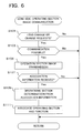
- FIG. 6 is a flowchart showing operation of operation section image communication at a lens side of the first embodiment of the invention.
- FIG. 7 is a flowchart showing operation of communication at a lens side of the first embodiment of the invention.
- FIG. 8A and FIG. 8B are drawings showing signal exchange between the camera body and the lens of one embodiment of the present invention.
- FIG. 9 is a timing chart showing one example of synchronization signals between the camera body and the lens in the imaging system of one embodiment of the present invention.
- FIG. 10A and FIG. 10B are drawings showing a relationship between an image transmitted from the lens side and an image displayed at the camera body side, in the imaging system of one embodiment of the present invention.
- FIG. 11 is a drawing showing a modified example of an operating section image in the imaging system of one embodiment of the present invention.
- FIG. 12A and FIG. 12B are drawings for describing usage states of the modified example of the imaging system of one embodiment of the present invention.
- FIG. 13A-FIG . 13 C are drawings showing display at the camera body side, for a modified example of the imaging system of the one embodiment of the present invention.
- FIG. 14A-FIG . 14 D are drawings showing display at the camera body side in the case where trimming mode has been selected, for a modified example of the imaging system of the one embodiment of the present invention.
- a camera of one preferred embodiment of the present invention is a digital camera, and has an imaging section, with a subject image being converted to image data by this imaging section, and the subject image then being subjected to live view display on a display section arranged on a rear surface of a body or in an ocular viewfinder etc. using image data based on this converted image data.
- a photographer determines composition and photo opportunity by looking at the live view display.
- image data is stored in a storage medium. Also, image data that has been stored in the storage medium can be played back and displayed on the display section if playback mode is selected.
- an operating section capable of rotating around the lens barrel is provided on the lens unit. If the lens unit is attached to the camera body, communication takes place between the camera body and the lens unit, and information relating to the operating section is transmitted from the lens unit. If the camera body receives information relating to the operating section, the information relating to the operating section is displayed on the display section, so that associating of the information relating to the operating section with functions of either the camera body or the interchangeable lens can be carried out on the display section.
- operating sections on the lens barrel side to be associated with operating sections for manual focus, to be associated with zooming operating sections, or to be associated with change operating sections for various modes such as exposure compensation, strobe mode etc.
- FIG. 1A and FIG. 1B is a block diagram showing the structure of an imaging system of one embodiment of the present invention, and the system comprises a camera body 10 , a lens unit 20 , and an ocular viewfinder 30 .
- the lens unit 20 is removably attached to the camera body 10 by means of a bayonet mount.
- the ocular viewfinder 30 can be attached to the camera body 10 by means of an adapter etc.
- the imaging system of this embodiment is a so-called interchangeable lens camera, in which the camera body 10 , lens unit 20 , and ocular viewfinder 30 are separately constructed, but it is also possible to have an integrally formed camera such as a so-called compact camera, or to have a camera where the camera body 10 and the ocular viewfinder 30 are integrally formed such as a so-called single lens reflex camera.
- a control section 21 , communication section 22 , ring operating section 23 a , lens operating section 23 b , drive sections 24 a , 24 b , position detection sections 25 a , 25 b , lens 26 and memory 27 are contained within the lens unit 20 .
- This lens unit 20 corresponds to a lens unit having a barrel section containing a photographing optical system, and an operating section provided on this barrel section.
- the control section 21 has a controller such as a CPU (Central Processing Unit), and performs control within the lens unit 20 in accordance with programs stored in the memory 27 . Specifically, the control section 21 performs communication with a signal processing and control section 1 within the camera body 10 by means of the communication section 22 , and transmits various information in response to requests from the signal processing and control section 1 within the camera body 10 . Also, the control section 21 executes operations such as focusing of the photographing lens 10 in accordance with instructions from the signals processing and control section 1 . In cases such as where the ring operating section 23 a has been assigned to zooming operations or manual focus operations, zooming operations or manual focus operations are executed in accordance with operation of the ring operating section 23 a.
- a controller such as a CPU (Central Processing Unit)
- the communication section 22 carries out communication with the communication section 11 within the camera body 10 . As described previously, when request signals have been received from the camera body 10 , lens state signals are transmitted in accordance with request signals by means of the communication section 22 . Details of this communication will be described later using FIG. 8A , FIG. 8B and FIG. 9 .
- the communication section 22 fulfills a function as a transmission section for transmitting information relating to operating sections of the lens unit 20 . This transmission section is also capable of transmitting information other than operating states relating to the operating sections to the camera body 10 . As information other than operating states relating to the operating sections, there is for example information representing at least one of focus position and focus length of the photographing lens 26 .
- the ring operating section 23 a is attached so as to be capable of rotation around the lens barrel of the lens unit 20 , and outputs signals generated in response to rotation to the control section 21 .
- the control section 21 detects rotation direction and rotation amount and rotational speed etc. based on the pulse signals, and transmit control signals in accordance with the rotational state or transmits signals representing the rotational state, to the camera body 10 by means of the communication section 22 .
- the ring operating section 23 a does not slide backwards and forwards in the optical axis direction, but in a modified example of the 1 embodiments that will be described later, a slide operation backwards and forwards in the optical axis direction is possible.
- the lens operating section 23 b is an operating section provided on the lens unit 20 besides the ring operating section 23 a , and is, for example, a push switch for changing mode. Also, in the modified example of the one embodiment that will be described later, it is a slide operation section for causing the ring operating section 23 a to slide in the optical axis direction.
- the ring operating section 23 a and the lens operating section 23 b fulfill a function as operating sections provided on the barrel section.
- the drive sections 24 a , 24 b are drive sections for a zoom control mechanism 26 a and a focus control mechanism 26 b within the photographing lens 26 .
- a lens within the photographing lens 26 is driven based on control signals from the control section 21 .
- the position detection sections 25 a , 25 b have encoders, detect focus position and focal length (zoom position) of the photographing lens 26 , and output detection results to the control section 21 .
- the photographing lens 26 has a photographing optical system made up of a plurality of optical lenses for forming a subject image, and in this embodiment the photographing optical system is constituted by a zoom lens optical system.
- the zoom control mechanism 26 a and the focus control mechanism 26 b are provided within the photographic lens 26 , and the drive sections 24 a , 24 b perform focus position adjustment (focus adjustment) and focal length adjustment (zoom adjustment) for the photographing lens 26 .
- an aperture mechanism is also provided, and control of aperture opening diameter is carried out based on control signals from the control section 21 .
- the memory 27 is constituted by a non-volatile memory such as flash memory, and as described previously stores programs for control.
- the memory 27 also stores an image of the operating section 23 used when carrying out lens association, which will be described later. This image is used as an operating section image 6 L shown in FIG. 2B , as will be described later.
- the memory 27 also stores various data such as focal length at the long focus end, focal length at the short focus end, maximum aperture diameter, and optical characteristics for the photographing lens 26 . These items of data are transmitted to the camera body 10 at the time of attaching the lens unit 20 to the camera body 10 , or in response to request signals from the camera body 10 .
- a signal processing and control section 1 , image sensor 2 , face detection section 3 , storage section 4 , communication section 5 , display section 6 , touch panel 7 , operation determination section 8 , clock section 9 , and communication section 11 are arranged inside the camera body 10 .
- the signal processing and control section 1 performs overall control of the control section 1 and the imaging system in accordance with programs stored in a memory, not shown.
- a lens operation association section 1 a , a lens operation determination section 1 b , a touch position determination section 1 c and a display control section 1 d are provided within the signal processing and control section 1 .
- the lens operation association section 1 a carries out processing to associate functions of the ring operating section 23 a of the lens unit 20 side in the camera body 10 .
- the lens operation association section 1 a carries out assigning all functions of the operation sections in accordance with the users intentions, such as, for example, carrying out a zooming operation, carrying out a manual focus operation, or carrying out mode processing, in response to a rotation operation of the ring operating section 23 a . This specific operation will be described later using FIG. 2A-FIG . 2 D.
- the lens operation determination section 1 b is input with information relating to operation of the ring operating section 23 a of the lens unit 20 by means of the communication section 22 and the communication section 14 , and determines operating state.
- the lens operation determination section 1 b is input with information relating to rotation direction and rotation amount of the ring operating section 23 a , and carries out determination of the operating state. If the ring operating section 23 a has been associated with mode processing by the lens operation association section 1 a , update of parameters for mode processing is carried out in accordance with rotation direction and rotation amount of the ring operating section 23 a that have been determined by the lens operation determination section 1 b.
- the touch position determination section 1 c is input with detection signals from the touch panel 7 , which will be described later, and determines at what position on the screen of the display section 6 the user has touched. As will be described later using FIG. 2A-FIG . 2 D, a lens operation association operation carries out setting according to the touch position by the user on the display section 6 .
- the display control section 1 d carries out control for display on the display section 6 .
- This display control section 1 d carries out various display controls, but one of them is display control at the time of a lens operation association operation. Specifically, when an image representing the operating section has been transmitted from the lens unit 20 , an icon for previously prepared function, for example, zooming, manual focus, or mode processing, is displayed on the display section 6 together with the image of the operating section.
- the lens operation association section 1 a , lens operation determination section 1 b , touch position determination section 1 c and a display control section 1 d etc. within the signal processing and control section 1 function as an associating section.
- This associating section displays information relating to the operating sections within the lens unit 20 that has been received by means of the communication section 11 functioning as a receiving section on the display section 6 , and it carries out association of the information relating to the operating sections and functions of the camera body.
- the associating section displays information relating to operating sections within the lens unit and functions of the camera body, detects an association operation carried out by the user and performs associating based on the detection results. The association operation carried out by the user is determined based on detection signals from the touch panel 7 .
- the image sensor 2 is a solid-state image sensor such as a CCD image sensor or a CMOS image sensor, and is arranged on the optical axis of the photographing lens 26 close to a position where a subject image is formed by the photographing lens. This image sensor 2 converts the subject image to an image signal. This image signal is output to the signal processing and control section 1 after being A/D converted to digital image data.
- the previously described photographing lens 26 and the image sensor 2 fulfill a function as an imaging section for converting a subject image formed by the photographing optical system into an electrical signal.
- the face detection section 3 is input with image data of the subject image and detects the face of a person etc. It is also possible to focus on a face that has been detected by this face detection section 3 .
- a focus detection circuit has been omitted from FIG. 1A and FIG. 1B , but it is possible to a suitably adopt well-known contrast AF where a contrast signal is obtained from image data and the photographing lens 26 is controlled so that this contrast value becomes a peak, or well-known phase difference AF where a defocus amount is obtained from a phase difference and the photographing lens 26 is controlled.
- the storage section 4 is a storage medium such as flash memory, and stores still image data or movie data for storage based on image data from the image sensor 2 . If playback mode is selected, image data that has been stored in the storage section 4 is read out, and the stored image is subjected to playback display on the display section 6 .
- the communication section 5 performs communication with the ocular viewfinder 30 , which will be described later.
- the ocular viewfinder 30 can be attached to the camera body 10 , and at the time of attachment, or when request signals are output from the signal processing and control section 1 , communication is carried out with the communication section 32 within the ocular viewfinder 30 .
- the display section 6 has a display such as an LCD (liquid crystal display) or organic EL arranged on a rear surface or the like of the camera body 10 .
- the display section 6 performs live view based on image data from the image sensor 2 , or displays an image that has been stored in the storage section 4 at the time of playback. Also, at the time of the lens operation association, display of icons representing the operation section (in this embodiment the ring operating section 23 a ) and functions of the lens unit 20 is carried out.
- the display section 6 may fulfill a function as a display section for displaying a subject image based on an electrical signal from the imaging section.
- the touch panel 7 is integrally formed with the front surface of the display section 6 or with the display section 6 , and outputs a detection signal corresponding to a position on the display section 6 that has been touched by the user to the signal processing and control section 1 .
- the touch panel 7 is capable of carrying out touch input on a screen for various camera settings. Also, as will be described later using FIG. 2B-FIG . 2 D, at the time of lens operation association an image of the operating section of the lens unit 20 and icons representing functions are used as input when the user performs association.
- the operation determination section 8 determines operating states of various operating members of the camera body 10 , such as a power supply button, release button, playback button, menu button etc.
- the signal processing and control section 1 executes various control based on operating states of the operating members determined by the operation determination section 8 .
- the clock section 9 has a clock function, and acquires time and date information such as the time of shooting, and fulfills a clock function at the time of a control operation by the signal processing and control section 1 .
- the communication section 11 carries out communication with the lens unit 20 , as was described previously. This communication section 11 fulfills a function as a receiving section for receiving information relating to operating section that has been transmitted from the lens unit.
- An eyepiece display section 31 and a communication section 32 are arranged in the ocular viewfinder 30 .
- the communication section 32 carries out communication with the communication section 5 at the camera body 10 side.
- the eyepiece display section 31 is an electronic viewfinder, and displays an image that has been input by means of the communication section 5 and the communication section 32 . For example live view display is carried out based on image data from the image sensor 2 .
- the eyepiece display section 31 may also fulfill a function as a display section for displaying a subject image based on an electrical signal from the imaging section.
- FIG. 2A shows the appearance of attaching a lens unit 20 and ocular viewfinder 30 to the camera body 10 , and a user looking through the ocular viewfinder 30 while holding the camera.
- the user's right hand is concentrating on operation of the release button arranged on an upper surface of the camera body 10
- the left hand is concentrating on operating the ring operating section 23 a to carry out the focus while supporting the lens unit 20 .
- This method of holding the camera shown in FIG. 2A is logical from the point of view of determining composition and photo opportunity, but the operation and adjustment the user wants to carry out is not necessarily focusing.
- this embodiment therefore, it is possible to associate the ring operating section 23 a of the lens unit 20 at the camera body 10 side so that it can also be used in adjustment of other functions.
- Association at the camera body 10 side is carried out by the display control section 1 d displaying an operating section image 6 L representing the ring operating section 23 a at the lens unit 20 side and icons 6 i representing functions to be associated with the ring operating section 23 a (in FIG. 2B there are three icons, namely “zoom” and “MF”, which are lens unit 20 side functions, and “mode” which is a camera body 10 side function) on the display section 6 , and the user then carrying out designation of a function they want to associate with the operating section 23 a (being displayed by the icons 6 i ) on the screen of the display section 6 .
- the lens operation association section 1 a sets the function of the ring operating section 23 a in accordance with the designation based on determination results from the touch position determination section 1 c .
- “mode” is set.
- the display control section 1 d displays modes 6 m that are subordinate to “mode” on the eyepiece display section 31 .
- modes 6 m are displayed, if the user peers into the ocular viewfinder 30 a screen as shown in FIG. 2C , namely “exposure”, “strobe”, and “self timer” etc., which are subordinate modes to “mode” is displayed. If a subject image can be seen during display of the subordinate modes it will be confusing, and so at this time live view display is turned off.
- the lens operation determination section 1 b determines operating state, and based on the results of this determination the display control section 1 d causes the selected subordinate mode 6 m to sequentially move in the rotation direction.
- the subordinate mode currently being selected is easily made visible by changing the color, for example, but this is not limited and it is also possible to identify that an item is being selected using a method such as flashing.
- a release button is pressed down.
- the release button is used to confirm the subordinate mode.
- FIG. 2D shows the appearance when exposure is confirmed as the subordinate mode, and the display control section 1 d displays a screen for carrying out parameter adjustment for exposure compensation on the eyepiece display section 31 . If the ring operating section 23 a is rotated in this state, the rotation is detected by the lens operation determination section 1 b , and it is possible to display changes in exposure compensation value on a parameter display 6 p based on the detection results. At the time of this parameter display for exposure compensation, live view display is restarted and it is possible to adjust the parameters for exposure compensation while viewing the appearance of the subject.
- the function that has been associated with the operating section image 6 L is transmitted from the camera body 10 to the lens unit 20 as an association result.
- the associated function is a function of the camera body 10
- the camera body 10 operates based on the set mode and parameters.
- the associated function is a function of the lens unit 20
- the lens unit 20 is operated based on the set mode.
- This operation is executed by the signal processing and control section 1 in accordance with programs stored in a memory, not shown, arranged in the camera body 10 .
- S 1 it is first determined whether or not a lens has been changed.
- S 1 it is determined, based on detection results from a lens detection section or the like, not shown, whether or not a lens unit 20 has gone from a state of not being attached to the camera body 10 to an attached state.
- step S 3 If the result of determination in step S 1 is that the lens has been changed, it is next determined whether or not it is a lens capable of operation member change (S 3 ). Depending on the model of the interchangeable lens that has been fitted, there may be cases where it is not possible to change the function of the operating section such as the ring operating section 23 a . In this step, therefore, communication is performed with the lens unit 20 , and it is determined whether or not the lens is capable of operation member change.
- step S 3 If the result of determination in step S 3 is that it is a lens capable of having the operation member changed, operation section image communication is next carried out (S 5 ). If the lens unit 20 that has been fitted is capable of operation member change then the operating section image 6 L representing the operating section is transmitted from the lens unit 20 to the camera body 10 .
- an association operation is carried out (S 7 ).
- operation of the ring operations section 26 a is associated with one of a plurality of functions. Details of this associating operation will be described later using FIG. 4 .
- step S 9 it is next determined whether or not the mode is exposure mode (S 9 ).
- the camera of this embodiment can select shooting mode and playback mode, and shooting mode is set as the default mode.
- step S 9 If the result of determination in step S 9 was that it is not shooting mode, it is next determined whether or not playback mode has been set (S 13 ). Playback mode is set if a playback button, for example is operated, and playback mode is released if the play button is pressed again. If the result of this determination is that it is not playback mode, processing returns to previously described step S 1 .
- step S 15 If the result of determination in step S 13 is that it is playback mode, image playback mode is executed (S 15 ). Here, image data stored in the storage section 4 within the camera body 10 is read out, and playback display on the display section 6 is carried out. Once image playback has been carried out, processing returns to step S 1 .
- step S 11 next imaging and image display are commenced (S 11 ).
- a subject image is subjected to photoelectric conversion in the image sensor 2 to acquire image data, and live view display on the display section 6 is commenced.
- communication is next carried out (S 21 ).
- communication of various data and control signals is carried out by means of the communication section 11 within the camera body 10 and the communication section 22 within the lens unit 20 .
- various data such as focal length at the long focus end, focal length at the short focus end, maximum aperture diameter, optical characteristics etc. of the photographic lens 26 , and an operation section image 6 L of the operation section 23 used when carrying out lens association, are communicated. Details of the lens communication will be described later using FIG. 9 .
- the lens operation determination section 1 b carries out determination based on a signal representing operating state of the ring operating section 23 a that has been input by means of the communication sections 11 and 22 .
- step S 25 it is next determined whether or not processing at the camera side is required (S 25 ).
- processing at the camera side is required (S 25 ).
- functions processed at the lens unit 20 side such as zooming or manual focus
- functions processed at the camera body 10 such as mode processing.
- this step it is determined whether or not a function that has been associated is processed at the camera body 10 side.
- step S 25 If the result of determination in step S 25 is that there is processing at the camera side, a camera operation using the ring is next carried out (S 27 ).
- setting of a subordinate mode and parameter adjustment etc. are carried out in accordance with the rotation operation of the ring operating section 23 a . Detailed operation for a camera operation using this ring will be described later using FIG. 5 .
- step S 29 it is next determined whether or not to take a picture. Once the user has viewed a subject image displayed on the ocular viewfinder 30 or the display section 6 and determined composition etc. the release button is pressed down fully. Determination in this step is carried out based on whether or not the release button has been pressed down fully.
- step S 31 If the result of determination in step S 29 is that a picture is to be taken, shooting and storage are carried out (S 31 ).
- image data from the image sensor 2 has been subjected to image processing by the image processing and control section 1 , image data is stored in the storage section 4 .
- processing returns to step S 1 .
- step S 29 If the result of determination in step S 29 is that a photograph is not to be taken, it is determined whether or not there has been a function change operation (S 33 ). If an operating member of the camera body 10 , for example a help button etc., is operated, or if a function change operation is carried out on a menu screen or the like, a function change for the ring operating section 23 a is carried out. In this step it is therefore determined whether or not these function change operations have been performed. If the result of this determination is that there has not been a function change operation, processing returns to step S 1 .
- a function change operation S 33
- step S 33 If the result of determination in step S 33 is that a function change operation was performed, a function change request is next carried out to the lens (S 35 ).
- the function change request is transmitted by means of communication with the lens unit 20 .
- one function from among the plurality of functions is selected and associated with the ring operating section 23 a of the lens unit 20 (S 1 -S 7 , S 33 , S 35 ). Also, when an associated function carries out processing at the camera body 10 side, the camera body 10 executes processing in accordance with operation of the ring operating section 23 a.
- step S 41 If the associating operation flow is entered, it is first determined whether or not an image has been received (S 41 ). As described previously, since operation section image communication is carried out in step S 5 , in this step it is determined whether or not this operation section image has been received. Depending on the lens unit 20 , there may be cases where it does not have an associated function, and the operation section image is not transmitted. In this step in this receipt is therefore confirmed.
- step S 41 lens image display is carried out (S 43 ) and the icon is determined in accordance with the lens and displayed (S 45 ).
- an operating section image 6 L and icons 6 i are displayed on the display section 6 .
- the operation section image 6 L is the image that was transmitted from the lens unit 20
- the icons 6 i are determined depending on the functions of the camera body 10 and the lens unit 20 . Details of the display method for the operation section image 6 L and the icons 6 i will be described later using FIG. 10A and FIG. 10B .
- the icons 6 i are displayed in a uniform manner, and it is also possible to make functions that cannot be executed, depending on the function of the camera body 10 and the lens unit 20 , unselectable.
- step S 47 If the result of determination in step S 47 is that there is no slide detection, it is determined whether or not a specified time has elapsed (S 57 ), and if the specified time has not elapsed processing returns to step S 47 .
- a standby state is entered during the time taken for the user to perform the slide operation.
- step S 47 If the result of determination in step S 47 is that there is slide detection, it is next determined whether the slide stop point or end point is the operating section image (S 49 ).
- the touch position determination section 1 c detects the position of the slide start point or the slide end point, and it is determined whether or not this position is on or in the vicinity of the operation section image 6 L.
- step S 49 If the result of determination in step S 49 is that the slide stop point or endpoint is the operating section image, it is next determined whether the slide start point or endpoint is an icon part (S 51 ).
- the touch position determination section 1 c detects the position of the slide start point or the slide end point, and it is determined whether this position is one of the plurality of icons 6 i , or in the vicinity thereof.
- step S 51 If the result of determination in step S 51 is that the slide start point and end point are at an icon portion, next the operation section and an icon function are associated.
- the ring operating section 23 a corresponding to the operation section image 6 L is associated with a function corresponding to the icon 6 i at the slide point.
- the function of the ring operating section 23 a is associated with mode setting.
- association information is next transmitted (S 55 ).
- the result of the association that was carried out in step S 53 is transmitted from the camera body 10 to the lens unit 20 side by means of the communication section 11 .
- the lens unit 20 side transmits only operating state of the ring operating section 23 a to the camera body 10 .
- the control section 21 of the lens unit 20 executes zooming or manual focus in accordance with the operating state of the ring operating section 23 a.
- step S 57 if the result of determination in step S 57 is that the specified time has elapsed, or if the result of determination in step S 49 is that the slide start point and end point are not at an operation section image, or if the result of determination in step S 51 is that the slide start point and end point are not at an icon portion, it is next determined whether or not an association has already been performed. It is determined whether or not an association was already performed in step S 53 .
- step S 59 If the result of determination in step S 59 is that an association has already been performed, the previous association is maintained (S 61 ). On the other hand, if the result of determination in step S 59 is that an association has not yet been performed, or if the result of determination in step S 41 is that an image has not been received, a default association is carried out (S 63 ). It is possible to determine suitable design values as a default.
- step S 63 Once the default association has been carried out in step S 63 , or if the previous association has been maintained in step S 61 , or if transmission of the association information has been carried out in step S 55 , the original flow is returned to.
- one function from among the plurality of function represented by the icons 6 i is selected in accordance with the user's slide operation, and associated with the ring operating section 23 a.
- step S 27 camera operation using the ring in step S 27 (refer to FIG. 3 ) will be described using FIG. 5 .
- this camera operation using the ring as described previously, in the case where the function that has been associated is processed in the camera body 10 , setting of a subordinate mode and parameter adjustment etc. is carried out in accordance with the rotation operation of the ring operating section 23 a.
- the lens operation determination section 1 b carries out determination based on a signal representing operating state of the ring operating section 23 a that has been input by means of the communication sections 11 and 22 .
- step S 71 If the result of determination in step S 71 is that there has been a ring operation, it is determined whether or not it is a body function (S 73 ). Here, it is determined whether or not the function of the ring operating section 23 a that was associated in step S 53 is a camera body 10 side function.
- step S 75 it is next determined whether or not there is mode switching (S 75 ). If there is mode switching, as was described using FIG. 2 , since subordinate mode setting is carried out, in this step it is determined whether or not there is mode switching of the function that has been associated.
- next mode display is carried out together with removing a taken image (S 77 ).
- “strobe”, “exposure” and “self” are displayed on the eyepiece display section 31 , and based on image data from the image sensor 2 live view display is turned off.
- rotation amount determination is carried out (S 79 ).
- the lens operation determination section 1 b determines rotation direction and rotation amount of the ring operating section 23 a based on signals from the lens unit 20 .
- corresponding mode switching is carried out (S 81 ).
- corresponding mode switching is carried out in accordance with rotation direction and rotation amount of the ring operating section 23 a that were determined in step S 79 .
- the corresponding mode is switched sequentially in the order “strobe” ⁇ “exposure” ⁇ “self” ⁇ “return” ⁇ “strobe”. “return” is an icon for completing subordinate mode setting.
- step S 85 it is next determined whether or not there is a subordinate mode (S 85 ). If exposure has been selected as the subordinate mode in step S 83 , there is no subordinate mode. However depending on the selected subordinate mode, there may be further subordinate modes. It is therefore determined in this step whether or not there is a further subordinate mode.
- subordinate modes for example, a zoom operation has optical zoom or electronic zoom, and focus has course adjustment and fine adjustment. For mode selection also, subordinate to an art filter mode, what image processing is selected, and to what extent the processing is performed and whether or not there is blending etc. can also be considered.
- step S 85 If the result of determination in step S 85 is that there are further subordinate modes, the subordinate modes are displayed and mode switching continues (S 87 ). On the other hand, if the result of determination is that there are no further subordinate modes, the mode is determined, and display of a taken image is recommenced (S 89 ). Here, together with determining the mode, live view display is recommenced based on image data from the image sensor 2 .
- step S 91 parameter numerical value display is carried out (S 91 ).
- it is a case where there is no further mode switching for instance, a case where “exposure”, which is a subordinate mode to mode switching, has been determined, as shown in FIG. 2D .
- step S 91 -S 95 parameter adjustment is carried out in accordance with a rotation operation of the ring operating section 23 a .
- step S 91 display of parameter numerical values for carrying out parameter adjustment are displayed. Also, at this time, since live view display is being performed, it is possible for the user to carry out parameter adjustment while looking at the subject.
- step S 93 rotation amount determination is carried out.
- the lens operation determination section 1 b determines rotation direction and rotation amount of the ring operating section 23 a based on signals from the lens unit 20 .
- switching of corresponding parameters is next carried out (S 95 ).
- switching of parameter numerical values is carried out in accordance with rotation amount that was determined in step S 93 .
- step S 95 the original processing flow is returned to.
- This operating image communication is processing flow executed by the control section 21 of the lens unit 20 in step S 5 (refer to FIG. 3 ) at times such as when a transmission request for an operating section image has been transmitted from the camera body 10 side.
- step S 101 it is first determined whether or not a lens has been changed or if there is a change request.
- the lens unit 20 has been attached to the camera body 10 , or whether or not a request to transmit an operating section image has been received from the camera body 10 (refer to step S 35 ( FIG. 3 )).
- step S 101 If the result of determination in step S 101 is that there is a lens change or change request, it is next determined whether or not communication is possible (S 103 ). Here, it is determined whether or not communication is possible with the camera body 10 by means of the communication sections 22 and 11 .
- step S 105 If the result of determination in step S 103 is that communication is possible, transmission of an operation section image is next carried out (S 105 ).
- an image of the ring operating section 23 a stored in the memory 27 (corresponding to the operation section image 6 L) is transmitted to the camera body 10 .
- association information is transmitted in step S 107 . If the operating section and icon function are associated, then since association information is transmitted in step S 55 (refer to FIG. 4 ), in this step it is determined whether or not this information has been received.
- step S 107 If the result of determination in step S 107 is that association information has been received, operation section determination is next carried out from the association information (S 109 ) and the operation section and the function are associated (S 111 ).
- association of the function that was designated by the user in step S 53 (refer to FIG. 4 ) with the designated operation section (with this embodiment, the ring operating section 23 a ) is carried out from the received association information. In this way it is made possible, for example, to assign zooming and manual focus etc. as functions of the rings operating section 23 a.
- step S 111 If association of the operation section and the function has been carried out in step S 111 , or if the result of determination in step S 101 is that there was no lens change or update request, or if the result of determination in step S 103 is that communication is not possible, or if the result of determination in step S 107 is that association information was not received, the lens side operation section image communication is terminated and the original main flow is returned to.
- lens state is first determined (S 121 ).
- various lens states such as lens position, aperture opening, rotational state of the ring operating section 23 a etc. within the lens unit 20 are determined by the position detection sections 25 a , 25 b , ring operating section 23 a , lens operating section 23 b etc.
- lens control operation it is next determined whether or not there has been a lens control operation (S 123 ).
- the determination result becomes yes.
- lens control is carried out (S 125 ).
- an operation is carried out in accordance with the operating state of the ring operating section 23 a.
- step S 127 it is next determined whether or not there is communication. Since communication is carried out at the camera body 10 in step S 21 (refer to FIG. 3 ), communication is also carried out at the lens unit 20 side in response to the communication request at this time.
- step S 129 If the result of determination in step S 127 is that there is communication, lens state communication is carried out next (S 129 ). Here, state of the lens unit 20 is transmitted in response to the request from the camera body 10 .
- lens control is carried out (S 131 ).
- control is carried out in accordance with the instruction. For example, in the case where an AF control instruction has been issued from the camera body 10 , control such as focusing is carried out in accordance with the AF control instruction.
- step S 131 Once the lens control in step S 131 has been carried out, or if the result of determination in step S 127 is that communication is not carried out, the lens communication flow is terminated and the original main flow is returned to.
- control is carried out in accordance with lens state, and if control signals are received from the camera body 10 control is carried out in accordance with the control signals.
- FIG. 8A shows exchange of signals when a function is associated with the operating section.
- the lens unit 20 transmits an operating section image (lens image) (refer to S 105 in FIG. 6 ).
- the operating section image is displayed at time T 3 (refer to S 43 in FIG. 4 ).
- a touch signal 1 for a touch start point
- a touch signal 2 for a touch end point is transmitted from the camera body 10 to the lens unit 20 at time T 5 .
- transmission of the touch signals 1 and 2 to the lens unit 20 is in order to notify that there has been an association operation from the camera body 10 side to the lens unit 20 side.
- an operation in progress signal is transmitted to the lens unit 20 side control section 21 , and it becomes possible to prevent unforeseen control etc. with the lens unit 20 . It is an important signal from the point of view of preventing errors during operation.
- association of an operation member and a function is performed, and association information is transmitted to the lens unit 20 (S 53 and S 55 of FIG. 4 , and S 109 and S 111 of FIG. 6 ).
- slide determination is carried out at the camera body 10 side, but it is also possible to carry out determination at the lens unit 20 side.
- information on slide start point and end point are required information on the position where touch was started and the position where touch was ended are transmitted one at a time.
- this is not limiting, and it is also possible to sequentially transmit point information such as that representing a slide locus. In these cases, it is preferable to have a configuration where start point and endpoint are determined from this locus at the lens unit 20 .
- FIG. 8B shows signal exchange at the time of lens operation.
- the camera body 10 performs a communication request to the lens unit 20 (refer to S 21 in FIG. 3 ).
- the lens unit 20 carries out lens state communication for the communication request (refer to S 129 in FIG. 7 ), and at time T 13 the camera body 10 carries out switching in the event that there is a corresponding function (refer to S 27 in FIG. 3 ).
- the same operations are repeated for time T 14 -T 16 and time T 17 -T 19 .
- FIG. 9 the horizontal axis represents the flow of time, while the vertical axis represents respective processing content and timing.
- process B 1 display of a live view image, and calculation of an AF evaluation value, are carried out using image data that was acquired in the previous frame.
- process B 2 AF calculations and various setting changes etc. are carried out based on lens state data that was acquired from lens state communication.
- a vertical synchronization signal is a signal that is output in correspondence with each frame.
- imaging and readout a subject image is formed on the image sensor 2 , and image data of this formed image is read out.
- the imaging and readout have a rhombus shape in FIG. 9 , which is because in this embodiment, at the time of acquiring a live view image a rolling shutter is adopted, and imaging and readout are carried out sequentially every pixel line.
- a lens state data request command is transmitted from the camera body 10 to the lens unit 20 , and this command requests transmission of data representing the lens state of the lens unit 20 to the camera body 10 . Also in the communication LB, the lens unit 20 transmits data representing the lens state to the camera body 10 in response to the lens state data request command.
- a lens communication synchronization signal is generated in response to a vertical synchronization signal in the camera body 10 , and this lens communication synchronization signal is output to the lens unit 20 from a synchronization signal terminal of the communication section 11 of the camera body 10 .
- a lens position acquisition signal changes state at a predetermined time, for example, with the example shown in FIG. 9 , at a time point after a time point substantially at the central point time of a charge accumulation time of the image sensor 2 .
- processing L 1 within the lens unit 20 is processing to acquire position information of the focusing lens within the photographing lens 26 at a time where the lens position acquisition signal changes state, and detect operating state of the ring operating section 23 a at a time when the lens communication synchronization signal is received.
- processing L 2 is processing to transmit position information of the focusing lens and lens state data such as operating state of the ring operating section 23 a , in response to a lens state data request command that has been received from the camera body 10 .
- processing B 1 within the camera body 10 is executed in synchronization with the vertical synchronization signal, and a lens communication synchronization signal is transmitted to the lens unit 20 in synchronization with the vertical synchronization signal.
- a lens state data request command is transmitted to the lens unit 20 by communication BL.
- the lens state is detected and lens state data is transmitted by communication LB.
- the camera body 10 receives the lens state data and then executes processing B 2 .
- processing L 1 for acquiring lens position acquired by the position detection sections 25 a , 25 b is executed in synchronization with a lens position acquisition signal.
- This lens position acquisition signal is generated at a predetermined time, and with the example shown in FIG. 9 at a time point after half of a charge accumulation time has elapsed at the screen center of the image sensor 2 .
- the lens unit 20 acquires position information of the focusing lens 25 a , using the position detection section 25 b for detecting position of the photographing lens at the time of state change of the lens position acquisition signal.
- These synchronous communications are all executed in synchronization with the lens communication synchronization signal.
- FIG. 10A shows image data coordinates for the operation section image 6 L.
- coordinates for the lower left corner of the operating section image are made (0,0)
- coordinates of the upper right corner are made (XL, YL)
- coordinates of a lower corner of a line segment that divides the image into 2 equal parts are made (XL/2, 0)
- coordinates of an upper corner of this line segment are made (XL/2, YL).
- Image data of the operation section image 6 L is stored in the memory 27 together with these coordinates.
- image data of this operation section image 6 L is transmitted from the lens unit 20 to the camera body 10 , it is displayed from coordinates (X0, Y0) to (X1, Y1) on a display panel of the display section 6 , as shown in FIG. 10B . Control of this display position is carried out by the display control section 1 d within the signal processing and control section 1 .
- the coordinates of the operation section image 6 L are stored from (XL/2, 0) to (XL/2, YL) of the memory 27 within the lens unit 20 . If this coordinate information is required by the display control section 1 d at the camera body 10 side, and the fact that positions from (XL+(X1+X0)/2, Y0) to (X0+(X1+X0)/2, Y1) has been touched is detected by the touch position detection section 1 c , it is determined that the user has touched the operation section image 6 L.
- display control for the icons 6 i is carried out by the display control section 1 d of the camera body 10 , and which one of the plurality of icons has been touched is determined by the touch position determination section 1 c .
- the camera body 10 side display control section 1 d carries out display control, but this is not limiting, and it is also possible for part or all of the display control to be carried out by the control section 21 within the lens unit 20 .
- FIG. 11 a modified example of the operation section image will be described using FIG. 11 .
- a display of the operating section was carried out using an image (operation section image 6 L).
- operation section image 6 L an image
- a lens ring 6 La and the lens switch 6 Lb can also be displayed.
- a lens switch corresponding to the lens operating section 23 b can also be associated.
- the ring operating section 23 a is rotatable around the barrel of the lens unit 20 , and slides back and forth along the optical axis direction. Specifically, in FIG. 12A the ring operating section 23 a is at position A which is towards the front in the optical axis direction, and in FIG. 12B is at position the which is towards the rear in the optical axis direction.
- the lens operating section 23 b has a slide mechanism that slides to position A or to position B, and slide positions A and B are detected by a switch, not shown.
- FIG. 13A-FIG . 13 C show display of the modified example of the operating section in the display section 6 .
- FIG. 13A is a state where an image of the operating section and icons are displayed, in steps S 43 and S 45 .
- the operation section image 6 L shows that the ring operating section 23 a is capable of moving to position A and position B, and the icons 6 i indicate functions that are capable of being associated.
- FIG. 14 shows a trimming method in the case where trimming has been set in FIG. 13C . If the ring operating section 23 a is at position A, then as shown in FIG. 14A , an operation section display 31 a and a frame 31 b showing the range of an optical zoom are displayed superimposed on liveview display. If the ring operating section 23 a is slid in the optical axis direction towards position B while in this state, the mode switches to trimming mode.
- the frame 31 b is displayed with a face position detected by the face detection section 3 as a center. Since “expand/contract” is displayed to the side of the operation section display 31 a , the user can understand that it is possible to expand or contract by trimming, using a rotation operation of the ring operating section 23 a.
- a plurality of operating sections (the ring operating section 23 a and the lens operating section 23 b ) are respectively associated with functions. Assigning functions to the plurality of operating sections results in a number of combinations of operating section and function, and function rich assignment is made possible in variations. Also, if the association section associates the ring operation section with a function of the camera body, mode switching or parameter switching are carried out in accordance with rotation amount of the ring operation section.
- the user's association operation at the time of carrying out association was carried out based on detection signals from the touch panel 7 .
- the user operation when associating information relating to an operating section with a function of the camera body or the lens unit is not limited to one on the display panel, and it is also possible to carry out detection using another operation member, such as a cross-shaped button.
- mode switching and parameter adjustment at the time of carrying out association were carried out using a rotation operation of the ring operating section 23 a .
- this is not limiting, and it is also possible to perform switching and adjustment using an operating member at the camera body 10 side.
- a display section for when carrying out association either the display section 6 arranged on the rear surface or the like of the camera body 10 of the eyepiece display section 31 within the ocular viewfinder 30 are used.
- selection of the display section can be suitably changed, and it is possible to use only one of them.
- the display section also serves as a display panel for live view display, but it is also possible to provide a dedicated display section, or to have a configuration where the display section is combined with another display section.
- the lens unit is an interchangeable lens, but it is also possible to have a lens unit that is integrated with the camera body.
- a digital camera has been described as a device for taking pictures, but as a camera it is possible to have a digital single lens reflex camera, a compact digital camera, or a movie camera etc.
- the present invention is not limited to the above-described embodiments, and structural elements may be modified in actual implementation within the scope of the gist of the embodiments. It is also possible form various inventions by suitably combining the plurality structural elements disclosed in the above described embodiments. For example, it is possible to omit some of the structural elements shown in the embodiments. It is also possible to suitably combine structural elements from different embodiments.
Landscapes
- Engineering & Computer Science (AREA)
- Multimedia (AREA)
- Signal Processing (AREA)
- Human Computer Interaction (AREA)
- Studio Devices (AREA)
- Structure And Mechanism Of Cameras (AREA)
- Lens Barrels (AREA)
- Camera Bodies And Camera Details Or Accessories (AREA)
- Indication In Cameras, And Counting Of Exposures (AREA)
Abstract
Description
Claims (12)
Priority Applications (1)
| Application Number | Priority Date | Filing Date | Title |
|---|---|---|---|
| US14/605,048 US9602705B2 (en) | 2011-11-07 | 2015-01-26 | Imaging system and control method for imaging system |
Applications Claiming Priority (2)
| Application Number | Priority Date | Filing Date | Title |
|---|---|---|---|
| JP2011243150A JP6168720B2 (en) | 2011-11-07 | 2011-11-07 | Shooting system |
| JP2011-243150 | 2011-11-07 |
Related Child Applications (1)
| Application Number | Title | Priority Date | Filing Date |
|---|---|---|---|
| US14/605,048 Continuation US9602705B2 (en) | 2011-11-07 | 2015-01-26 | Imaging system and control method for imaging system |
Publications (2)
| Publication Number | Publication Date |
|---|---|
| US20130141624A1 US20130141624A1 (en) | 2013-06-06 |
| US8970774B2 true US8970774B2 (en) | 2015-03-03 |
Family
ID=48523756
Family Applications (2)
| Application Number | Title | Priority Date | Filing Date |
|---|---|---|---|
| US13/670,616 Expired - Fee Related US8970774B2 (en) | 2011-11-07 | 2012-11-07 | Imaging system and control method for imaging system |
| US14/605,048 Active US9602705B2 (en) | 2011-11-07 | 2015-01-26 | Imaging system and control method for imaging system |
Family Applications After (1)
| Application Number | Title | Priority Date | Filing Date |
|---|---|---|---|
| US14/605,048 Active US9602705B2 (en) | 2011-11-07 | 2015-01-26 | Imaging system and control method for imaging system |
Country Status (2)
| Country | Link |
|---|---|
| US (2) | US8970774B2 (en) |
| JP (1) | JP6168720B2 (en) |
Cited By (3)
| Publication number | Priority date | Publication date | Assignee | Title |
|---|---|---|---|---|
| US20150138438A1 (en) * | 2011-11-07 | 2015-05-21 | Olympus Imaging Corp. | Imaging system and control method for imaging system |
| US11064109B2 (en) * | 2019-09-27 | 2021-07-13 | Canon Kabushiki Kaisha | Shooting control apparatus, image capture apparatus, and shooting control method |
| US11206357B2 (en) | 2019-09-27 | 2021-12-21 | Canon Kabushiki Kaisha | Shooting control apparatus, image capture apparatus, and shooting control method |
Families Citing this family (17)
| Publication number | Priority date | Publication date | Assignee | Title |
|---|---|---|---|---|
| JP6088733B2 (en) * | 2011-11-29 | 2017-03-01 | オリンパス株式会社 | Imaging device |
| JP6112819B2 (en) * | 2012-10-10 | 2017-04-12 | オリンパス株式会社 | Electronic device, driving method and program |
| US9571722B2 (en) * | 2013-02-27 | 2017-02-14 | Google Technology Holdings LLC | Viewfinder utility |
| JP6137965B2 (en) * | 2013-07-01 | 2017-05-31 | オリンパス株式会社 | Electronic device, electronic device control method, and electronic device control program |
| JP6081887B2 (en) * | 2013-08-19 | 2017-02-15 | 日本電産コパル株式会社 | Imaging device |
| JP6216568B2 (en) * | 2013-08-19 | 2017-10-18 | 日本電産コパル株式会社 | Imaging device |
| JP6372121B2 (en) * | 2014-03-19 | 2018-08-15 | カシオ計算機株式会社 | Imaging apparatus, shooting setting method, and program |
| JP6436764B2 (en) * | 2014-12-25 | 2018-12-12 | キヤノン株式会社 | Display control apparatus and control method thereof |
| JP6185200B2 (en) * | 2014-12-26 | 2017-08-23 | 富士フイルム株式会社 | Lens barrel and control method thereof, camera body and control method thereof, photographing apparatus and control method thereof |
| US20170035955A1 (en) * | 2015-03-27 | 2017-02-09 | Eliaz Therapeutics, Inc. | Apheresis based treatment for kidney disease |
| KR101675435B1 (en) * | 2015-05-11 | 2016-11-22 | 유한회사 마스터이미지쓰리디아시아 | High Brightness Stereoscopic Projection Device Using Asymmetric Driving of Modulators and Operating Method For the Same |
| DE112017004252T5 (en) * | 2016-09-21 | 2019-06-13 | Fujifilm Corporation | Camera and display control method of the camera |
| JP6748582B2 (en) * | 2017-01-10 | 2020-09-02 | キヤノン株式会社 | Imaging device, control method thereof, program, and recording medium |
| JP6833535B2 (en) * | 2017-02-03 | 2021-02-24 | キヤノン株式会社 | Imaging device, control method and program of imaging device |
| US10873691B2 (en) | 2017-05-31 | 2020-12-22 | Canon Kabushiki Kaisha | Accessory apparatus and imaging apparatus |
| JP7309383B2 (en) * | 2019-02-25 | 2023-07-18 | キヤノン株式会社 | Imaging device |
| DE102020112458A1 (en) * | 2020-05-07 | 2021-11-11 | Arnold & Richter Cine Technik Gmbh & Co. Betriebs Kg | Remote control device for a video camera and identification ring for a remote control device |
Citations (12)
| Publication number | Priority date | Publication date | Assignee | Title |
|---|---|---|---|---|
| US6392702B1 (en) * | 1990-10-15 | 2002-05-21 | Canon Kabushiki Kaisha | Image pickup apparatus with lens unit detection and recording |
| US6445416B1 (en) * | 1995-06-30 | 2002-09-03 | Canon Kabushiki Kaisha | Image pickup apparatus having electronic zoom function based on optical zooming focal length variation with time |
| US20090251558A1 (en) * | 2008-04-04 | 2009-10-08 | Samsung Techwin Co., Ltd. | Fast and low-power digital camera with gps |
| US20100208122A1 (en) * | 2007-10-15 | 2010-08-19 | Panasonic Corporation | Camera body and imaging device |
| US20100238321A1 (en) * | 2007-09-28 | 2010-09-23 | Panasonic Corporation | Camera body, interchangeable lens unit, and camera system |
| US7924339B2 (en) * | 2006-02-28 | 2011-04-12 | Canon Kabushiki Kaisha | Image pickup apparatus having a help function, and method and program for controlling the same |
| US20110129151A1 (en) | 2009-11-27 | 2011-06-02 | Sony Corporation | Image processing apparatus, image processing method, program, and recording medium |
| US20110164164A1 (en) * | 2008-09-11 | 2011-07-07 | Panasonic Corporation | Imaging device |
| US20110199498A1 (en) * | 2010-02-16 | 2011-08-18 | Yoshinori Matsuzawa | Image pickup apparatus |
| US20110267503A1 (en) * | 2010-04-28 | 2011-11-03 | Keiji Kunishige | Imaging apparatus |
| US20120127189A1 (en) * | 2010-11-19 | 2012-05-24 | Samsung Electronics Co., Ltd. | Digital image processing apparatus and method of controlling the same |
| US20140098273A1 (en) * | 2012-10-10 | 2014-04-10 | Olympus Imaging Corp. | Electronic device, driving method of the same, and computer readable recording medium |
Family Cites Families (10)
| Publication number | Priority date | Publication date | Assignee | Title |
|---|---|---|---|---|
| AT394786B (en) * | 1988-03-16 | 1992-06-25 | Arri Cine & Video Geraete | MACRO LENS WITH A REMOVAL RING BEARED ON THE LENS HOUSING |
| GB2271646B (en) | 1992-10-19 | 1996-12-04 | Asahi Optical Co Ltd | An optical camera and a method of conducting a focusing operation therein |
| JP3283076B2 (en) * | 1992-10-19 | 2002-05-20 | 旭光学工業株式会社 | Camera with electric zoom function |
| JP2003177294A (en) * | 2001-12-13 | 2003-06-27 | Nikon Corp | Lens barrel, accessory, image pickup device main body and image pickup system |
| JP2003259177A (en) * | 2002-03-04 | 2003-09-12 | Minolta Co Ltd | Digital camera |
| JP2005292325A (en) * | 2004-03-31 | 2005-10-20 | Matsushita Electric Ind Co Ltd | Camera, imaging apparatus, lens barrel and camera main body |
| KR100763188B1 (en) * | 2005-07-21 | 2007-10-04 | 삼성전자주식회사 | Method for displaying menu and digital device using the same |
| JP2007033775A (en) * | 2005-07-26 | 2007-02-08 | Canon Inc | Imaging apparatus |
| JP5457217B2 (en) * | 2010-02-02 | 2014-04-02 | オリンパスイメージング株式会社 | camera |
| JP6168720B2 (en) * | 2011-11-07 | 2017-07-26 | オリンパス株式会社 | Shooting system |
-
2011
- 2011-11-07 JP JP2011243150A patent/JP6168720B2/en not_active Expired - Fee Related
-
2012
- 2012-11-07 US US13/670,616 patent/US8970774B2/en not_active Expired - Fee Related
-
2015
- 2015-01-26 US US14/605,048 patent/US9602705B2/en active Active
Patent Citations (12)
| Publication number | Priority date | Publication date | Assignee | Title |
|---|---|---|---|---|
| US6392702B1 (en) * | 1990-10-15 | 2002-05-21 | Canon Kabushiki Kaisha | Image pickup apparatus with lens unit detection and recording |
| US6445416B1 (en) * | 1995-06-30 | 2002-09-03 | Canon Kabushiki Kaisha | Image pickup apparatus having electronic zoom function based on optical zooming focal length variation with time |
| US7924339B2 (en) * | 2006-02-28 | 2011-04-12 | Canon Kabushiki Kaisha | Image pickup apparatus having a help function, and method and program for controlling the same |
| US20100238321A1 (en) * | 2007-09-28 | 2010-09-23 | Panasonic Corporation | Camera body, interchangeable lens unit, and camera system |
| US20100208122A1 (en) * | 2007-10-15 | 2010-08-19 | Panasonic Corporation | Camera body and imaging device |
| US20090251558A1 (en) * | 2008-04-04 | 2009-10-08 | Samsung Techwin Co., Ltd. | Fast and low-power digital camera with gps |
| US20110164164A1 (en) * | 2008-09-11 | 2011-07-07 | Panasonic Corporation | Imaging device |
| US20110129151A1 (en) | 2009-11-27 | 2011-06-02 | Sony Corporation | Image processing apparatus, image processing method, program, and recording medium |
| US20110199498A1 (en) * | 2010-02-16 | 2011-08-18 | Yoshinori Matsuzawa | Image pickup apparatus |
| US20110267503A1 (en) * | 2010-04-28 | 2011-11-03 | Keiji Kunishige | Imaging apparatus |
| US20120127189A1 (en) * | 2010-11-19 | 2012-05-24 | Samsung Electronics Co., Ltd. | Digital image processing apparatus and method of controlling the same |
| US20140098273A1 (en) * | 2012-10-10 | 2014-04-10 | Olympus Imaging Corp. | Electronic device, driving method of the same, and computer readable recording medium |
Cited By (4)
| Publication number | Priority date | Publication date | Assignee | Title |
|---|---|---|---|---|
| US20150138438A1 (en) * | 2011-11-07 | 2015-05-21 | Olympus Imaging Corp. | Imaging system and control method for imaging system |
| US9602705B2 (en) * | 2011-11-07 | 2017-03-21 | Olympus Corporation | Imaging system and control method for imaging system |
| US11064109B2 (en) * | 2019-09-27 | 2021-07-13 | Canon Kabushiki Kaisha | Shooting control apparatus, image capture apparatus, and shooting control method |
| US11206357B2 (en) | 2019-09-27 | 2021-12-21 | Canon Kabushiki Kaisha | Shooting control apparatus, image capture apparatus, and shooting control method |
Also Published As
| Publication number | Publication date |
|---|---|
| US9602705B2 (en) | 2017-03-21 |
| US20150138438A1 (en) | 2015-05-21 |
| JP2013097352A (en) | 2013-05-20 |
| US20130141624A1 (en) | 2013-06-06 |
| JP6168720B2 (en) | 2017-07-26 |
Similar Documents
| Publication | Publication Date | Title |
|---|---|---|
| US8970774B2 (en) | Imaging system and control method for imaging system | |
| US8605188B2 (en) | Camera having a rear-surface display section and an in-viewfinder display section | |
| US9001255B2 (en) | Imaging apparatus, imaging method, and computer-readable storage medium for trimming and enlarging a portion of a subject image based on touch panel inputs | |
| US7505679B2 (en) | Image-taking apparatus | |
| US9140960B2 (en) | Apparatus for processing an image having detachable lens and a ring for setting photographing parameter values | |
| JP2019219583A (en) | Electronic device and control method therefor | |
| JP2011155595A (en) | Information processing apparatus, control method and program thereof | |
| JP5846921B2 (en) | Shooting system | |
| JP6643036B2 (en) | Zoom control device, control method for zoom control device, control program for zoom control device, and storage medium | |
| JP6745682B2 (en) | Imaging device, control method, program, and storage medium | |
| JP2010141778A (en) | Imaging apparatus | |
| JP6410778B2 (en) | Imaging apparatus and control method thereof | |
| JP6410884B2 (en) | Operation setting device, operation setting method, and program | |
| JP2019219584A (en) | Electronic device and control method therefor | |
| JP7446913B2 (en) | Electronic devices, control methods for electronic devices, and programs | |
| JP7134730B2 (en) | Imaging device and its control method | |
| US20240137642A1 (en) | Imaging apparatus | |
| JP7071197B2 (en) | Imaging device and its control method | |
| JP2009053641A (en) | Imaging apparatus | |
| JP7279411B2 (en) | Imaging device | |
| JP7171252B2 (en) | IMAGING CONTROL DEVICE AND METHOD FOR CONTROLLING IMAGING CONTROL DEVICE | |
| JP2011154104A (en) | View angle center deviation correction device and view angle deviation correction method | |
| JP6452336B2 (en) | Imaging apparatus and control method thereof | |
| US20100123791A1 (en) | Digital image processing apparatus and method of controlling the same | |
| JP2006098547A (en) | Camera device and lens filter device |
Legal Events
| Date | Code | Title | Description |
|---|---|---|---|
| AS | Assignment |
Owner name: OLYMPUS IMAGING CORP., JAPAN Free format text: ASSIGNMENT OF ASSIGNORS INTEREST;ASSIGNORS:TOMIZAWA, MASAOMI;NONAKA, OSAMU;REEL/FRAME:029284/0598 Effective date: 20121105 |
|
| STCF | Information on status: patent grant |
Free format text: PATENTED CASE |
|
| AS | Assignment |
Owner name: OLYMPUS CORPORATION, JAPAN Free format text: MERGER;ASSIGNOR:OLYMPUS IMAGING CORP.;REEL/FRAME:036616/0332 Effective date: 20150401 |
|
| AS | Assignment |
Owner name: OLYMPUS CORPORATION, JAPAN Free format text: CHANGE OF ADDRESS;ASSIGNOR:OLYMPUS CORPORATION;REEL/FRAME:039344/0502 Effective date: 20160401 |
|
| MAFP | Maintenance fee payment |
Free format text: PAYMENT OF MAINTENANCE FEE, 4TH YEAR, LARGE ENTITY (ORIGINAL EVENT CODE: M1551); ENTITY STATUS OF PATENT OWNER: LARGE ENTITY Year of fee payment: 4 |
|
| AS | Assignment |
Owner name: OM DIGITAL SOLUTIONS CORPORATION, JAPAN Free format text: ASSIGNMENT OF ASSIGNORS INTEREST;ASSIGNOR:OLYMPUS CORPORATION;REEL/FRAME:058294/0274 Effective date: 20210730 |
|
| FEPP | Fee payment procedure |
Free format text: MAINTENANCE FEE REMINDER MAILED (ORIGINAL EVENT CODE: REM.); ENTITY STATUS OF PATENT OWNER: LARGE ENTITY |
|
| LAPS | Lapse for failure to pay maintenance fees |
Free format text: PATENT EXPIRED FOR FAILURE TO PAY MAINTENANCE FEES (ORIGINAL EVENT CODE: EXP.); ENTITY STATUS OF PATENT OWNER: LARGE ENTITY |
|
| STCH | Information on status: patent discontinuation |
Free format text: PATENT EXPIRED DUE TO NONPAYMENT OF MAINTENANCE FEES UNDER 37 CFR 1.362 |
|
| FP | Lapsed due to failure to pay maintenance fee |
Effective date: 20230303 |