US8900190B2 - Insertion device systems and methods - Google Patents
Insertion device systems and methods Download PDFInfo
- Publication number
- US8900190B2 US8900190B2 US12/553,038 US55303809A US8900190B2 US 8900190 B2 US8900190 B2 US 8900190B2 US 55303809 A US55303809 A US 55303809A US 8900190 B2 US8900190 B2 US 8900190B2
- Authority
- US
- United States
- Prior art keywords
- carrier body
- device housing
- housing
- needle
- insertion system
- Prior art date
- Legal status (The legal status is an assumption and is not a legal conclusion. Google has not performed a legal analysis and makes no representation as to the accuracy of the status listed.)
- Active, expires
Links
Images


Classifications
-
- A—HUMAN NECESSITIES
- A61—MEDICAL OR VETERINARY SCIENCE; HYGIENE
- A61M—DEVICES FOR INTRODUCING MEDIA INTO, OR ONTO, THE BODY; DEVICES FOR TRANSDUCING BODY MEDIA OR FOR TAKING MEDIA FROM THE BODY; DEVICES FOR PRODUCING OR ENDING SLEEP OR STUPOR
- A61M5/00—Devices for bringing media into the body in a subcutaneous, intra-vascular or intramuscular way; Accessories therefor, e.g. filling or cleaning devices, arm-rests
- A61M5/14—Infusion devices, e.g. infusing by gravity; Blood infusion; Accessories therefor
- A61M5/142—Pressure infusion, e.g. using pumps
- A61M5/14244—Pressure infusion, e.g. using pumps adapted to be carried by the patient, e.g. portable on the body
- A61M5/14248—Pressure infusion, e.g. using pumps adapted to be carried by the patient, e.g. portable on the body of the skin patch type
-
- A—HUMAN NECESSITIES
- A61—MEDICAL OR VETERINARY SCIENCE; HYGIENE
- A61M—DEVICES FOR INTRODUCING MEDIA INTO, OR ONTO, THE BODY; DEVICES FOR TRANSDUCING BODY MEDIA OR FOR TAKING MEDIA FROM THE BODY; DEVICES FOR PRODUCING OR ENDING SLEEP OR STUPOR
- A61M5/00—Devices for bringing media into the body in a subcutaneous, intra-vascular or intramuscular way; Accessories therefor, e.g. filling or cleaning devices, arm-rests
- A61M5/14—Infusion devices, e.g. infusing by gravity; Blood infusion; Accessories therefor
- A61M5/158—Needles for infusions; Accessories therefor, e.g. for inserting infusion needles, or for holding them on the body
-
- A—HUMAN NECESSITIES
- A61—MEDICAL OR VETERINARY SCIENCE; HYGIENE
- A61M—DEVICES FOR INTRODUCING MEDIA INTO, OR ONTO, THE BODY; DEVICES FOR TRANSDUCING BODY MEDIA OR FOR TAKING MEDIA FROM THE BODY; DEVICES FOR PRODUCING OR ENDING SLEEP OR STUPOR
- A61M5/00—Devices for bringing media into the body in a subcutaneous, intra-vascular or intramuscular way; Accessories therefor, e.g. filling or cleaning devices, arm-rests
- A61M5/14—Infusion devices, e.g. infusing by gravity; Blood infusion; Accessories therefor
- A61M5/142—Pressure infusion, e.g. using pumps
- A61M5/14244—Pressure infusion, e.g. using pumps adapted to be carried by the patient, e.g. portable on the body
- A61M5/14248—Pressure infusion, e.g. using pumps adapted to be carried by the patient, e.g. portable on the body of the skin patch type
- A61M2005/14252—Pressure infusion, e.g. using pumps adapted to be carried by the patient, e.g. portable on the body of the skin patch type with needle insertion means
-
- A—HUMAN NECESSITIES
- A61—MEDICAL OR VETERINARY SCIENCE; HYGIENE
- A61M—DEVICES FOR INTRODUCING MEDIA INTO, OR ONTO, THE BODY; DEVICES FOR TRANSDUCING BODY MEDIA OR FOR TAKING MEDIA FROM THE BODY; DEVICES FOR PRODUCING OR ENDING SLEEP OR STUPOR
- A61M5/00—Devices for bringing media into the body in a subcutaneous, intra-vascular or intramuscular way; Accessories therefor, e.g. filling or cleaning devices, arm-rests
- A61M5/14—Infusion devices, e.g. infusing by gravity; Blood infusion; Accessories therefor
- A61M5/142—Pressure infusion, e.g. using pumps
- A61M5/14244—Pressure infusion, e.g. using pumps adapted to be carried by the patient, e.g. portable on the body
- A61M2005/14268—Pressure infusion, e.g. using pumps adapted to be carried by the patient, e.g. portable on the body with a reusable and a disposable component
-
- A—HUMAN NECESSITIES
- A61—MEDICAL OR VETERINARY SCIENCE; HYGIENE
- A61M—DEVICES FOR INTRODUCING MEDIA INTO, OR ONTO, THE BODY; DEVICES FOR TRANSDUCING BODY MEDIA OR FOR TAKING MEDIA FROM THE BODY; DEVICES FOR PRODUCING OR ENDING SLEEP OR STUPOR
- A61M5/00—Devices for bringing media into the body in a subcutaneous, intra-vascular or intramuscular way; Accessories therefor, e.g. filling or cleaning devices, arm-rests
- A61M5/14—Infusion devices, e.g. infusing by gravity; Blood infusion; Accessories therefor
- A61M5/158—Needles for infusions; Accessories therefor, e.g. for inserting infusion needles, or for holding them on the body
- A61M2005/1583—Needle extractors
-
- A—HUMAN NECESSITIES
- A61—MEDICAL OR VETERINARY SCIENCE; HYGIENE
- A61M—DEVICES FOR INTRODUCING MEDIA INTO, OR ONTO, THE BODY; DEVICES FOR TRANSDUCING BODY MEDIA OR FOR TAKING MEDIA FROM THE BODY; DEVICES FOR PRODUCING OR ENDING SLEEP OR STUPOR
- A61M5/00—Devices for bringing media into the body in a subcutaneous, intra-vascular or intramuscular way; Accessories therefor, e.g. filling or cleaning devices, arm-rests
- A61M5/14—Infusion devices, e.g. infusing by gravity; Blood infusion; Accessories therefor
- A61M5/158—Needles for infusions; Accessories therefor, e.g. for inserting infusion needles, or for holding them on the body
- A61M2005/1585—Needle inserters
-
- A—HUMAN NECESSITIES
- A61—MEDICAL OR VETERINARY SCIENCE; HYGIENE
- A61M—DEVICES FOR INTRODUCING MEDIA INTO, OR ONTO, THE BODY; DEVICES FOR TRANSDUCING BODY MEDIA OR FOR TAKING MEDIA FROM THE BODY; DEVICES FOR PRODUCING OR ENDING SLEEP OR STUPOR
- A61M2209/00—Ancillary equipment
- A61M2209/04—Tools for specific apparatus
- A61M2209/045—Tools for specific apparatus for filling, e.g. for filling reservoirs
-
- A—HUMAN NECESSITIES
- A61—MEDICAL OR VETERINARY SCIENCE; HYGIENE
- A61M—DEVICES FOR INTRODUCING MEDIA INTO, OR ONTO, THE BODY; DEVICES FOR TRANSDUCING BODY MEDIA OR FOR TAKING MEDIA FROM THE BODY; DEVICES FOR PRODUCING OR ENDING SLEEP OR STUPOR
- A61M5/00—Devices for bringing media into the body in a subcutaneous, intra-vascular or intramuscular way; Accessories therefor, e.g. filling or cleaning devices, arm-rests
- A61M5/14—Infusion devices, e.g. infusing by gravity; Blood infusion; Accessories therefor
- A61M5/1413—Modular systems comprising interconnecting elements
-
- A—HUMAN NECESSITIES
- A61—MEDICAL OR VETERINARY SCIENCE; HYGIENE
- A61M—DEVICES FOR INTRODUCING MEDIA INTO, OR ONTO, THE BODY; DEVICES FOR TRANSDUCING BODY MEDIA OR FOR TAKING MEDIA FROM THE BODY; DEVICES FOR PRODUCING OR ENDING SLEEP OR STUPOR
- A61M5/00—Devices for bringing media into the body in a subcutaneous, intra-vascular or intramuscular way; Accessories therefor, e.g. filling or cleaning devices, arm-rests
- A61M5/14—Infusion devices, e.g. infusing by gravity; Blood infusion; Accessories therefor
- A61M5/142—Pressure infusion, e.g. using pumps
- A61M5/145—Pressure infusion, e.g. using pumps using pressurised reservoirs, e.g. pressurised by means of pistons
- A61M5/1452—Pressure infusion, e.g. using pumps using pressurised reservoirs, e.g. pressurised by means of pistons pressurised by means of pistons
- A61M5/1456—Pressure infusion, e.g. using pumps using pressurised reservoirs, e.g. pressurised by means of pistons pressurised by means of pistons with a replaceable reservoir comprising a piston rod to be moved into the reservoir, e.g. the piston rod is part of the removable reservoir
-
- Y—GENERAL TAGGING OF NEW TECHNOLOGICAL DEVELOPMENTS; GENERAL TAGGING OF CROSS-SECTIONAL TECHNOLOGIES SPANNING OVER SEVERAL SECTIONS OF THE IPC; TECHNICAL SUBJECTS COVERED BY FORMER USPC CROSS-REFERENCE ART COLLECTIONS [XRACs] AND DIGESTS
- Y10—TECHNICAL SUBJECTS COVERED BY FORMER USPC
- Y10T—TECHNICAL SUBJECTS COVERED BY FORMER US CLASSIFICATION
- Y10T29/00—Metal working
- Y10T29/49—Method of mechanical manufacture
- Y10T29/49826—Assembling or joining
Definitions
- Embodiments of the present invention relate generally to insertion device systems and methods and, in specific embodiments, to insertion device systems and methods for insertion into a patient.
- certain chronic diseases may be treated by delivering a medication or other substance to the body of a patient.
- diabetes is a chronic disease that is commonly treated by delivering defined amounts of insulin to a patient at appropriate times.
- manually operated syringes and insulin pens have been employed for delivering insulin to a patient.
- modern systems have been designed to include programmable pumps for delivering controlled amounts of medication to a patient.
- External pump type delivery devices have been configured in external devices, which connect to a patient, and have been configured in implantable devices, which are implanted inside of the body of a patient.
- External pump type delivery devices include devices designed for use in a stationary location, such as a hospital, a clinic, or the like, and further include devices configured for ambulatory or portable use, such as devices designed to be carried by a patient, or the like.
- External pump-type delivery devices may contain reservoirs of fluidic media, such as, but is not limited to, insulin.
- External pump-type delivery devices may be connected in fluid flow communication to a patient or user-patient, for example, through suitable hollow tubing.
- the hollow tubing may be connected to a hollow needle that is designed to pierce the skin of the patient and to deliver fluidic media there through.
- the hollow tubing may be connected directly to the patient as through a cannula, or the like.
- External pump-type delivery devices may be connected in fluid-flow communication to a patient-user, for example, through suitable hollow tubing.
- the hollow tubing may be connected to a hollow needle that is designed to pierce the patient-user's skin and deliver an infusion medium to the patient-user.
- the hollow tubing may be connected directly to the patient-user as or through a cannula or set of micro-needles.
- a manual insertion of the needle into the patient-user can be somewhat traumatic to the user-patient.
- insertion mechanisms have been made to assist the insertion of a needle into the user-patient, whereby a needle is forced by a spring to move quickly from a retracted position into an extended position. As the needle is moved into the extended position, the needle is quickly forced through the skin of the user-patient in a single, relatively abrupt motion that can be less traumatic to certain user-patients as compared to a slower, manual insertion of a needle.
- Pump-type delivery devices can allow accurate doses of insulin to be calculated and delivered automatically to a patient-user at any time during the day or night. Furthermore, when used in conjunction with glucose sensors or monitors, insulin pumps may be automatically controlled to provide appropriate doses of infusion medium at appropriate times of need, based on sensed or monitored levels of blood glucose.
- Pump-type delivery devices have become an important aspect of modern medical treatments of various types of medical conditions, such as diabetes. As pump technologies improve and as doctors and patient-users become more familiar with such devices, the popularity of external medical infusion pump treatment increases and is expected to increase substantially over the next decade.
- An insertion system in accordance with an embodiment of the present invention may include, but is not limited to, a base, a first device housing, and a second device housing.
- the base may be adapted to be carried by a patient.
- the first device housing may be configured to be operatively engaged with and disengaged from the base.
- the first device housing may include a first carrier body.
- the first carrier body may be arranged for movement within at least a portion of the first device housing at least between a retracted position and an advanced position.
- the first carrier body may be for supporting a piercing member in a position orientated for insertion through skin of the patient upon movement of the first carrier body from the retracted position to the advanced position.
- the second device housing may be configured to be operatively engaged with and disengaged from the first device housing.
- the second device housing may include a second carrier body and a driver.
- the second carrier body may be arranged for movement within at least a portion of the second device housing at least between a refracted position and an advanced position.
- the second carrier body may be operatively connectable with the first carrier body.
- the driver may be arranged within the second device housing to move the first carrier body from the retracted position toward the advanced position to insert at least a portion of the piercing member through skin of the patient.
- the driver may be arranged within the second device housing to move the second carrier body from the retracted position toward the advanced position to move the first carrier body from the retracted position toward the advanced position to insert at least a portion of the piercing member through skin of the patient.
- the insertion system may further include a locking mechanism. The locking mechanism may be adapted to operatively engage at least one of the driver and the second carrier body and to substantially prevent premature release of the carrier body before securing the insertion system in position against the skin of the patient.
- the first carrier body may be configured to operatively engage the base when the first carrier body is moved to the advanced position. In some embodiments, the first carrier body may be configured to disengage the first device housing from the base upon the first carrier body being moved to the advanced position.
- one of the base and the first device housing may have an aperture.
- the other of the base and the first device housing may have a lever for engaging the aperture to operatively engage the first device housing to the base.
- the first carrier body may have at least one protrusion for disengaging the lever from the aperture upon the first carrier body being moved to the advanced position.
- one of the base and the first device housing may have an aperture.
- the other of the base and the first device housing may have a lever for engaging the aperture to operatively engage the first device housing to the base.
- the first carrier body may include a plunger. The plunger may be configured to support the piercing member, and to insert the piercing member in the skin of the user-patient upon movement of the first carrier body from the retracted position to the advanced position.
- a distance traveled by the first carrier body relative to the first device housing from the retracted position to the advanced position may be equal to at least a distance traveled by the second carrier body relative to the second device housing from the retracted position to the advanced position. In various embodiments, a distance traveled by the first carrier body relative to the first device housing from the refracted position to the advanced position may be equal to at least a distance required to insert the piercing member into the skin of the patient.
- the first carrier body may include a plunger and a collar body.
- the collar body may be operatively connected to the plunger.
- the piercing member may be supported by at least one of the plunger and the collar body in a position orientated for insertion through the skin of the patient upon movement of the first carrier body from the retracted position to the advanced position.
- the piercing member may comprise a cannula supported by the collar body and a needle supported by the plunger.
- the needle may be disposed at least partially through the cannula.
- the cannula and the needle may be supported in a position orientated for insertion through the skin of the patient upon movement of the first carrier body from the retracted position to the advanced position.
- the plunger and the needle may be removable from the collar body.
- the cannula and the collar body may be adapted for reuse with another collar body and cannula.
- the collar body may have a fluid channel in fluid communication with a hollow interior of the cannula. The fluid channel may be for operatively connecting to a reservoir for containing fluidic media when the first carrier body is in the advanced position to allow fluidic medic to flow from the reservoir to the hollow interior of the cannula.
- the insertion system may include a compliant material.
- the compliant material may be arranged within the first carrier body to support the piercing member.
- the compliant material may be for allowing articulation of the piercing member relative to the first carrier body in a case where at least a portion of the piercing member is in the skin of the patient and the piercing member is moved relative to the housing.
- the piercing member may comprise a needle.
- the driver may comprise a bias member.
- the bias member may be arranged within the second device housing.
- the bias member may be for urging the second carrier body toward the advanced position.
- the insertion system may include a second driver.
- the second driver may be arranged within the second device housing to move the first carrier body away from the advanced position to a third position.
- the second driver may comprise a bias member.
- the bias member may be arranged within the second device housing.
- the bias member may be for urging the second carrier body toward the third position.
- the insertion system may include a trigger.
- the trigger may be for releasably retaining the second carrier body in the advanced position.
- the trigger may be configured to be operable to release the second carrier body to allow the second carrier body to move to the third position.
- the insertion system may include a trigger.
- the trigger may be for releasably retaining the second carrier body in the retracted position.
- the trigger may be configured to be operable to release the second carrier body to allow the second carrier body to move to the advanced position.
- the second carrier body may be configured to operatively connect with at least two different types of piercing members.
- the second carrier body may be configured to insert at least a portion of a selected one of the at least two different types of piercing members in a case where the selected one of the at least two different types of piercing members is operatively connected to the second carrier body and the second carrier body is moved to the advanced position.
- the second carrier body may be configured to be removable from the selected one of the at least two different types of piercing members and adapted for reuse with another one of the at least two different types of piercing members.
- the insertion system may be removable from the selected one of the at least two different types of piercing members. In further embodiments, the insertion system may be completely removable from the selected one of the at least two different types of piercing members.
- the piercing member may be supported by the first carrier body is one of the at least two different types of piercing members.
- the selected one of the at least two different types of piercing members may be an insertion needle of an insertion set.
- the selected one of the at least two different types of piercing members may be a lancet for obtaining a fluid sample from the patient.
- the insertion system may include a guard.
- the guard may be configured to be removably attachable to the second device housing.
- the guard may have an aperture for allowing the lancet to extend through in a case where the lancet is operatively connected to the second carrier body and the second carrier body is moved to the advanced position.
- a distance traveled by the first carrier body relative to the first device housing from the retracted position to the advanced position may be equal to at least a distance required to insert the selected one of the at least two different types of piercing members in the skin of the patient that is at least equal to an implantable length of the selected one of the at least two different types of piercing members.
- a method of making an insertion system in accordance with an embodiment of the present invention may include, but is not limited to any one or combination of, (i) adapting a base to be carried by a patient; (ii) configuring a first device housing to be operatively engaged with and disengaged from the base; (iii) arranging a first carrier body for movement within at least a portion of the first device housing at least between a refracted position and an advanced position, the first carrier body for supporting a piercing member in a position orientated for insertion through skin of the patient upon movement of the first carrier body from the retracted position to the advanced position; (iv) configuring a second device housing to be operatively engaged with and disengaged from the first device housing, the second device housing comprising; (v) arranging a second carrier body for movement within at least a portion of the second device housing at least between a retracted position and an advanced position, the second carrier body operatively connectable with the first carrier body; and (vi) arranging a
- An insertion system in accordance with an embodiment of the present invention may include, but is not limited to, a housing, a piercing member, and a compliant material.
- the piercing member may be arranged at least partially within the housing, the piercing member for piercing a membrane.
- the compliant material may be arranged within the housing to support the piercing member.
- the compliant material may be for allowing articulation of the piercing member relative to the housing in a case where the piercing member is in the membrane and moved relative to the housing.
- the compliant material may be for allowing articulation of the piercing member relative to the housing in a case where the piercing member is in the membrane and moved laterally relative to the housing. In various embodiments, the compliant material may be for allowing pivotal movement of the piercing member relative to the housing in a case where the piercing member is in the membrane and moved laterally relative to the housing. In various embodiments, the compliant material may be adapted to provide a seal between the piercing member and the compliant material to substantially prevent fluidic media from flowing between the compliant material and the piercing member.
- the insertion system may include a seal member.
- the seal member may be arranged between the compliant material and the piercing member for substantially preventing fluidic media from flowing between the compliant material and the piercing member.
- the compliant material may be adapted to adhere to the piercing member.
- the compliant material may be arranged to support the piercing member such that the piercing member does not contact the housing.
- the piercing member may have a first opening and a second opening.
- One of the first opening and the second opening may be for receiving fluidic media into a hollow interior of the piercing member.
- the other of the one of the first opening and the second opening may be for allowing the fluidic media to exit the hollow interior of the needle.
- the compliant material may be arranged at least partially in between the first opening and the second opening. In some embodiments, the compliant material may be arranged completely between the first opening and the second opening.
- the piercing member may have a first opening and a second opening.
- One of the first opening and the second opening may be for receiving fluidic media into a hollow interior of the piercing member.
- the other of the one of the first opening and the second opening may be for allowing the fluidic media to exit the hollow interior of the needle.
- the compliant material may have a body for supporting the piercing member.
- the body may have a recess in communication with one of the first opening and the second opening.
- the recess may be defined by a surface sloped to correspond generally to an angle of articulation of the piercing member relative to the housing.
- the piercing member may comprise a needle.
- the housing may have a fluid channel for alignment with a reservoir. The fluid channel may be in fluid communication with a hollow interior of the piercing member.
- the housing may have a chamber for containing the compliant material. At least a portion of the needle may extend through the chamber of the housing.
- the insertion system may include a retaining member.
- the retaining member may be for retaining the compliant material within the housing.
- the retaining member may comprise at least one of a cap, glue joint, and a septum.
- the housing may be made of the compliant material to allow articulation of the piercing member relative to the housing in a case where the piercing member is moved relative to the housing.
- the membrane may comprise skin of a patient.
- the compliant material may be for allowing articulation of the piercing member relative to the housing in a case where the piercing member is in the skin of the patient and moved relative to the housing.
- the piercing member may have a hollow interior for conveying fluidic media.
- a method of making an insertion system in accordance with an embodiment of the present invention may include, but is not limited to any one or combination of, (i) providing a housing; (ii) arranging a piercing member at least partially within the housing, the piercing member for piercing a membrane; and (iii) arranging a compliant material within the housing to support the piercing member, the compliant material for allowing articulation of the piercing member relative to the housing in a case where the piercing member is in the membrane and moved relative to the housing.
- FIG. 1 illustrates a generalized representation of a system in accordance with an embodiment of the present invention
- FIG. 2 illustrates an example of a system in accordance with an embodiment of the present invention
- FIG. 3 illustrates an example of a delivery device in accordance with an embodiment of the present invention
- FIG. 4 illustrates a delivery device in accordance with an embodiment of the present invention
- FIG. 5A illustrates a durable portion of a delivery device in accordance with an embodiment of the present invention
- FIG. 5B illustrates a section view of a durable portion of a delivery device in accordance with an embodiment of the present invention
- FIG. 5C illustrates a section view of a durable portion of a delivery device in accordance with an embodiment of the present invention
- FIG. 6A illustrates a disposable portion of a delivery device in accordance with an embodiment of the present invention
- FIG. 6B illustrates a section view of a disposable portion of a delivery device in accordance with an embodiment of the present invention
- FIG. 6C illustrates a section view of a disposable portion of a delivery device in accordance with an embodiment of the present invention
- FIG. 7 illustrates portions of a medical device in accordance with an embodiment of the present invention
- FIG. 8 illustrates a medical device in accordance with an embodiment of the present invention
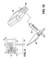
- FIG. 9 illustrates a medical device in accordance with an embodiment of the present invention.
- FIG. 10 illustrates a medical device in accordance with an embodiment of the present invention
- FIG. 11 illustrates a medical device in accordance with an embodiment of the present invention
- FIG. 12 illustrates a medical device in accordance with an embodiment of the present invention
- FIG. 13 illustrates a medical device in accordance with an embodiment of the present invention
- FIG. 14 illustrates a medical device in accordance with an embodiment of the present invention
- FIG. 15 illustrates a medical device in accordance with an embodiment of the present invention
- FIG. 16 illustrates cross-section of a needle-inserting device in accordance with an embodiment of the present invention
- FIG. 17 illustrates a medial device in accordance with an embodiment of the present invention
- FIG. 18 illustrates a medial device in accordance with an embodiment of the present invention
- FIG. 19 illustrates a medial device in accordance with an embodiment of the present invention
- FIG. 20 illustrates a medial device in accordance with an embodiment of the present invention
- FIG. 21 illustrates flow chart for using a medial device in accordance with an embodiment of the present invention
- FIG. 22 illustrates a medial device in accordance with an embodiment of the present invention
- FIG. 23 illustrates a medial device in accordance with an embodiment of the present invention
- FIG. 24 illustrates flow chart for using a medial device in accordance with an embodiment of the present invention
- FIG. 25 illustrates a medial device in accordance with an embodiment of the present invention.
- FIG. 26 illustrates a medial device in accordance with an embodiment of the present invention.
- FIG. 1 illustrates a generalized representation of a system 10 in accordance with an embodiment of the present invention.
- the system 10 may include a delivery device 12 .
- the system 10 may further include a sensing device 14 , a command control device (CCD) 16 , and a computer 18 .
- the delivery device 12 and the sensing device 14 may be secured at desired locations on the body 5 of a patient or user-patient 7 .
- the locations at which the delivery device 12 and the sensing device 14 are secured to the body 5 of the user-patient 7 in FIG. 1 are provided only as representative, non-limiting, examples.
- the system 10 , the delivery device 12 , the sensing device 14 , the CCD 16 , and computer 18 may be similar to those described in the following U.S. patent applications that were assigned to the assignee of the present invention, where each of following patent applications is incorporated herein by reference in its entirety: (i) U.S. patent application Ser. No. 11/211,095, filed Aug. 23, 2005, “Infusion Device And Method With Disposable Portion”; (ii) U.S. patent application Ser. No. 11/515,225, filed Sep. 1, 2006, “Infusion Medium Delivery Device And Method With Drive Device For Driving Plunger In Reservoir”; (iii) U.S. patent application Ser. No. 11/588,875, filed Oct.
- fluidic media may include a liquid, a fluid, a gel, or the like.
- fluidic media may include a medicine or a drug for treating a disease or a medical condition.
- fluidic media may include insulin for treating diabetes, or may include a drug for treating pain, cancer, a pulmonary disorder, HIV, or the like.
- fluidic media may include a nutritional supplement, a dye, a tracing medium, a saline medium, a hydration medium, or the like.
- the sensing device 14 may include a sensor, a monitor, or the like, for providing sensor data or monitor data.
- the sensing device 14 may be configured to sense a condition of the user-patient 7 .
- the sensing device 14 may include electronics and enzymes reactive to a biological condition, such as a blood glucose level, or the like, of the user-patient 7 .
- the sensing device 14 may be secured to the body 5 of the user-patient 7 or embedded in the body 5 of the user-patient 7 at a location that is remote from the location at which the delivery device 12 is secured to the body 5 of the user-patient 7 . In various other embodiments, the sensing device 14 may be incorporated within the delivery device 12 . In other embodiments, the sensing device 14 may be separate and apart from the delivery device, and may be, for example, part of the CCD 16 . In such embodiments, the sensing device 14 may be configured to receive a biological sample, analyte, or the like, to measure a condition of the user-patient 7 .
- the sensing device 14 and/or the delivery device 12 may utilize a closed-loop system.
- closed-loop systems Examples of sensing devices and/or delivery devices utilizing closed-loop systems may be found at, but are not limited to, the following references: (i) U.S. Pat. No. 6,088,608, entitled “Electrochemical Sensor And Integrity Tests Therefor”; (ii) U.S. Pat. No. 6,119,028, entitled “Implantable Enzyme-Based Monitoring Systems Having Improved Longevity Due To Improved Exterior Surfaces”; (iii) U.S. Pat. No. 6,589,229, entitled “Implantable Enzyme-Based Monitoring Systems Adapted for Long Term Use”; (iv) U.S. Pat.
- the sensing device 14 may be configured to sense a condition of the user-patient 7 , such as, but not limited to, blood glucose level, or the like.
- the delivery device 12 may be configured to deliver fluidic media in response to the condition sensed by the sensing device 14 .
- the sensing device 14 may continue to sense a new condition of the user-patient, allowing the delivery device 12 to deliver fluidic media continuously in response to the new condition sensed by the sensing device 14 indefinitely.
- the sensing device 14 and/or the delivery device 12 may be configured to utilize the closed-loop system only for a portion of the day, for example only when the user-patient is asleep or awake.
- Each of the delivery device 12 , the sensing device 14 , the CCD 16 , and the computer 18 may include transmitter, receiver, or transceiver electronics that allow for communication with other components of the system 10 .
- the sensing device 14 may be configured to transmit sensor data or monitor data to the delivery device 12 .
- the sensing device 14 may also be configured to communicate with the CCD 16 .
- the delivery device 12 may include electronics and software that are configured to analyze sensor data and to deliver fluidic media to the body 5 of the user-patient 7 based on the sensor data and/or preprogrammed delivery routines.
- the CCD 16 and the computer 18 may include electronics and other components configured to perform processing, delivery routine storage, and to control the delivery device 12 .
- the delivery device 12 may be made with more simplified electronics.
- the delivery device 12 may include all control functions, and may operate without the CCD 16 and the computer 18 .
- the CCD 16 may be a portable electronic device.
- the delivery device 12 and/or the sensing device 14 may be configured to transmit data to the CCD 16 and/or the computer 18 for display or processing of the data by the CCD 16 and/or the computer 18 .
- the sensing device 14 may be integrated into the CCD 16 . Such embodiments may allow the user-patient to monitor a condition by providing, for example, a sample of his or her blood to the sensing device 14 to assess his or her condition.
- the sensing device 14 and the CCD 16 may be for determining glucose levels in the blood and/or body fluids of the user-patient without the use of, or necessity of, a wire or cable connection between the delivery device 12 and the sensing device 14 and/or the CCD 16 .
- the CCD 16 may be for providing information to the user-patient that facilitates the user-patient's subsequent use of a drug delivery system.
- the CCD 16 may provide information to the user-patient to allow the user-patient to determine the rate or dose of medication to be administered into the body of the user-patient.
- the CCD 16 may provide information to the delivery device 12 to control the rate or dose of medication administered into the body of the user-patient
- FIG. 2 illustrates an example of the system 10 in accordance with an embodiment of the present invention.
- the system 10 in accordance with the embodiment illustrated in FIG. 2 includes the delivery device 12 and the sensing device 14 .
- the delivery device 12 in accordance with an embodiment of the present invention may include a disposable housing 20 , a durable housing 30 , and a reservoir system 40 .
- the delivery device 12 may further include an infusion path 50 .
- a disposable portion of the delivery device 12 may include the disposable housing 20 and the reservoir system 40 .
- the disposable portion of the delivery device 12 may be recommended for disposal after a specified number of uses.
- a durable portion of the delivery device 12 may include the durable housing 30 , electronics (not shown in FIG. 2 ), a drive device having a motor and drive linkage (not shown in FIG. 2 ), and the like. Elements of the durable housing portion of the delivery device 12 are typically not contaminated from contact with the user-patient or fluidic media during normal operation of the delivery device 12 and, thus, may be retained for re-use with replaced disposable portions of the delivery device 12 .
- the disposable housing 20 may support the reservoir system 40 and has a bottom surface (facing downward and into the page in FIG. 2 ) configured to secure to the body of the user-patient.
- An adhesive may be employed at an interface between the bottom surface of the disposable housing 20 and the skin of the user-patient to adhere the disposable housing 20 to the skin of the user-patient.
- the adhesive may be provided on the bottom surface of the disposable housing 20 , with a peelable cover layer covering the adhesive material. In this manner, the cover layer may be peeled off to expose the adhesive material, and the adhesive side of the disposable housing 20 may be placed against the user-patient, for example against the skin of the user-patient.
- the delivery device 12 may be attached to the skin of the user-patient.
- the disposable housing 20 and/or the remaining portions of the delivery device 12 may be worn or otherwise attached on or underneath clothing of the user-patient.
- the delivery device 12 may be supported by any suitable manner, such as, but not limited to, on a belt, in a pocket, and the like.
- Representative examples of such delivery devices 12 , and delivery devices in general, may include, but is not limited to, the MiniMed Paradigm 522 Insulin Pump, MiniMed Paradigm 722 Insulin Pump, MiniMed Paradigm 515 Insulin Pump, MiniMed Paradigm 715 Insulin Pump, MiniMed Paradigm 512 R Insulin Pump, MiniMed Paradigm 712 R Insulin Pump, MiniMed 508 Insulin Pump, MiniMed 508 R Insulin Pump, and any other derivatives thereof.
- the reservoir system 40 may be configured for containing or holding fluidic media, such as, but not limited to insulin.
- the reservoir system 40 may include a hollow interior volume for receiving fluidic media, such as, but not limited to, a cylinder-shaped volume, a tubular-shaped volume, or the like.
- the reservoir system 40 may be provided as a cartridge or canister for containing fluidic media.
- the reservoir system 40 can be refilled with fluidic media.
- the reservoir system 40 is pre-filled with fluidic media.
- the reservoir system 40 may be supported by the disposable housing 20 in any suitable manner.
- the disposable housing 20 may be provided with projections or struts (not shown), or a trough feature (not shown), for holding the reservoir system 40 .
- the reservoir system 40 may be supported by the disposable housing 20 in a manner that allows the reservoir system 40 to be removed from the disposable housing 20 and replaced with another reservoir.
- the reservoir system 40 may be secured to the disposable housing 20 by a suitable adhesive, a strap, or other coupling structure.
- the reservoir system 40 may include at least one port 41 for allowing fluidic media to flow into and/or flow out of the interior volume of the reservoir system 40 .
- the infusion path 50 may include a connector 56 , a tube 54 , and a needle apparatus 52 .
- the connector 56 of the infusion path 50 may be connectable to the port 41 of the reservoir system 40 .
- the disposable housing 20 may be configured with an opening near the port 41 of the reservoir system 40 for allowing the connector 56 of the infusion path 50 to be selectively connected to and disconnected from the port 41 of the reservoir system 40 .
- the port 41 of the reservoir system 40 may be covered with or supports a septum (not shown in FIG. 2 ), such as a self-sealing septum, or the like.
- the septum may be configured to prevent fluidic media from flowing out of the reservoir system 40 through the port 41 when the septum is not pierced.
- the connector 56 of the infusion path 50 may include a needle for piercing the septum covering the port 41 of the reservoir system 40 to allow fluidic media to flow out of the interior volume of the reservoir system 40 .
- the needle apparatus 52 of the infusion path 50 may include a needle that is able to puncture the skin of the user-patient.
- the tube 54 connects the connector 56 with the needle apparatus 52 and may be hollow, such that the infusion path 50 is able to provide a path to allow for the delivery of fluidic media from the reservoir system 40 to the body of a user-patient.
- the durable housing 30 of the delivery device 12 in accordance with various embodiments of the present invention includes a housing shell configured to mate with and secure to the disposable housing 20 .
- the durable housing 30 and the disposable housing 20 may be provided with correspondingly shaped grooves, notches, tabs, or other suitable features that allow the two parts to connect together easily, by manually pressing the two housings together, by twist or threaded connection, or other suitable manner of connecting the parts that is well known in the mechanical arts.
- the durable housing 30 and the disposable housing 20 may be connected to each other using a twist action.
- the durable housing 30 and the disposable housing 20 may be configured to be separable from each other when a sufficient force is applied to disconnect the two housings from each other.
- the disposable housing 20 and the durable housing 30 may be snapped together by friction fitting.
- a suitable seal such as an o-ring seal, may be placed along a peripheral edge of the durable housing 30 and/or the disposable housing 20 to provide a seal against water entering between the durable housing 30 and the disposable housing 20 .
- the durable housing 30 of the delivery device 12 may support a drive device (not shown in FIG. 2 ), including a motor and a drive device linkage portion, for applying a force to fluidic media within the reservoir system 40 to force fluidic media out of the reservoir system 40 and into an infusion path, such as the infusion path 50 , for delivery to a user-patient.
- a drive device (not shown in FIG. 2 ), including a motor and a drive device linkage portion, for applying a force to fluidic media within the reservoir system 40 to force fluidic media out of the reservoir system 40 and into an infusion path, such as the infusion path 50 , for delivery to a user-patient.
- an electrically driven motor may be mounted within the durable housing 30 with appropriate linkage for operatively coupling the motor to a plunger arm (not shown in FIG. 2 ) connected to a plunger head (not shown in FIG. 2 ) that is within the reservoir system 40 and to drive the plunger head in a direction to force fluidic media out of the port 41 of the reservoir
- the motor may be controllable to reverse direction to move the plunger arm and the plunger head to cause fluid to be drawn into the reservoir system 40 from a patient.
- the motor may be arranged within the durable housing 30 and the reservoir system 40 may be correspondingly arranged on the disposable housing 20 , such that the operable engagement of the motor with the plunger head, through the appropriate linkage, occurs automatically upon the user-patient connecting the durable housing 30 with the disposable housing 20 of the delivery device 12 .
- Further examples of linkage and control structures may be found in U.S. patent application Ser. No. 09/813,660, filed Mar. 21, 2001, entitled “Control Tabs for Infusion Devices and Methods of Using the Same,” which is incorporated herein by reference in its entirety.
- the durable housing 30 and the disposable housing 20 may be made of suitably rigid materials that maintain their shape, yet provide sufficient flexibility and resilience to effectively connect together and disconnect, as described above.
- the material of the disposable housing 20 may be selected for suitable compatibility with skin.
- the disposable housing 20 and the durable housing 30 of the delivery device 12 may be made of any suitable plastic, metal, composite material, or the like.
- the disposable housing 20 may be made of the same type of material or a different material relative to the durable housing 30 .
- the disposable housing 20 and the durable housing 30 may be manufactured by injection molding or other molding processes, machining processes, or combinations thereof.
- the disposable housing 20 may be made of a relatively flexible material, such as a flexible silicone, plastic, rubber, synthetic rubber, or the like.
- a relatively flexible material such as a flexible silicone, plastic, rubber, synthetic rubber, or the like.
- the delivery device 12 is connected to the sensing device 14 through a connection element 17 of the sensing device 14 .
- the sensing device 14 may include a sensor 15 that includes any suitable biological or environmental sensing device, depending upon a nature of a treatment to be administered by the delivery device 12 .
- the sensor 15 may include a blood glucose sensor, or the like.
- the sensor 15 may include a continuous glucose sensor.
- the continuous glucose sensor may be implantable within the body of the user-patient.
- the continuous glucose sensor may be located externally, for example on the skin of the user-patient, or attached to clothing of the user-patient.
- fluid may be drawn continually from the user-patient and sensed by the continuous glucose sensor.
- the continuous glucose sensor may be configured to sense and/or communicate with the CCD 16 continuously.
- the continuous glucose sensor may be configured to sense and/or communicate with the CCD 16 intermittently, for example sense glucose levels and transmit information every few minutes.
- the continuous glucose sensor may utilize glucose oxidase.
- the sensor 15 may be an external sensor that secures to the skin of a user-patient or, in other embodiments, may be an implantable sensor that is located in an implant site within the body of the user-patient. In further alternatives, the sensor may be included with as a part or along side the infusion cannula and/or needle, such as for example as shown in U.S. patent application Ser. No. 11/149,119, filed Jun. 8, 2005, entitled “Dual Insertion Set,” which is incorporated herein by reference in its entirety. In the illustrated example of FIG.
- the sensor 15 is an external sensor having a disposable needle pad that includes a needle for piercing the skin of the user-patient and enzymes and/or electronics reactive to a biological condition, such as blood glucose level or the like, of the user-patient.
- the delivery device 12 may be provided with sensor data from the sensor 15 secured to the user-patient at a site remote from the location at which the delivery device 12 is secured to the user-patient.
- FIG. 2 may include a sensor 15 connected by the connection element 17 for providing sensor data to sensor electronics (not shown in FIG. 2 ) located within the durable housing 30 of the delivery device 12
- other embodiments may employ a sensor 15 located within the delivery device 12
- a sensor 15 having a transmitter for communicating sensor data by a wireless communication link with receiver electronics (not shown in FIG. 2 ) located within the durable housing 30 of the delivery device 12
- a wireless connection between the sensor 15 and the receiver electronics within the durable housing 30 of the delivery device 12 may include a radio frequency (RF) connection, an optical connection, or another suitable wireless communication link.
- RF radio frequency
- Further embodiments need not employ the sensing device 14 and, instead, may provide fluidic media delivery functions without the use of sensor data.
- the disposable elements may be arranged on the disposable housing 20 , while durable elements may be arranged within a separable durable housing 30 .
- the disposable housing 20 may be separated from the durable housing 30 , so that the disposable housing 20 may be disposed of in a proper manner.
- the durable housing 30 may then be mated with a new (un-used) disposable housing 20 for further delivery operation with a user-patient.
- FIG. 3 illustrates an example of the delivery device 12 in accordance with another embodiment of the present invention.
- the delivery device 12 of the embodiment of FIG. 3 is similar to the delivery device 12 of the embodiment of FIG. 2 . While the delivery device 12 in the embodiment illustrated in FIG. 2 provides for the durable housing 30 to cover the reservoir system 40 , the delivery device 12 in the embodiment of FIG. 3 provides for the durable housing 30 to secure to the disposable housing 20 without covering the reservoir system 40 .
- the delivery device 12 of the embodiment illustrated in FIG. 3 includes the disposable housing 20 , and the disposable housing 20 in accordance with the embodiment illustrated in FIG. 3 includes a base 21 and a reservoir retaining portion 24 . In one embodiment, the base 21 and reservoir retaining portion 24 may be formed as a single, unitary structure.
- the base 21 of the disposable housing 20 may be configured to be securable to a body of a user-patient.
- the reservoir-retaining portion 24 of the disposable housing 20 is configured to house the reservoir system 40 .
- the reservoir-retaining portion 24 of the disposable housing 20 may be configured to have an opening to allow for the port 41 of the reservoir system 40 to be accessed from outside of the reservoir-retaining portion 24 while the reservoir system 40 is housed in the reservoir-retaining portion 24 .
- the durable housing 30 may be configured to be attachable to and detachable from the base 21 of the disposable housing 20 .
- the delivery device 12 in the embodiment illustrated in FIG. 3 includes a plunger arm 60 that is connected to or that is connectable to a plunger head (not shown in FIG. 3 ) within the reservoir system 40 .
- FIG. 4 illustrates another view of the delivery device 12 of the embodiment of FIG. 3 .
- the delivery device 12 of the embodiment illustrated in FIG. 4 includes the disposable housing 20 , the durable housing 30 , and the infusion path 50 .
- the disposable housing 20 in the embodiment of FIG. 4 includes the base 21 , the reservoir-retaining portion 24 , and a peelable cover layer 25 .
- the peelable cover layer 25 may cover an adhesive material on the bottom surface 22 of the base 21 .
- the peelable cover layer 25 may be configured to be peelable by a user-patient to expose the adhesive material on the bottom surface 22 of the base 21 . In some embodiments, there may be multiple adhesive layers on the bottom surface 22 of the base 21 that are separated by peelable layers.
- the infusion path 50 in accordance with the embodiment of the present invention illustrated in FIG. 4 includes the needle 58 rather than the connector 56 , the tube 54 , and the needle apparatus 52 as shown in the embodiment of FIG. 2 .
- the base 21 of the disposable housing 20 may be provided with an opening or pierceable wall in alignment with a tip of the needle 58 , to allow the needle 58 to pass through the base 21 and into the skin of a user-patient under the base 21 , when extended. In this manner, the needle 58 may be used to pierce the skin of the user-patient and deliver fluidic media to the user-patient.
- the needle 58 may be extended through a hollow cannula (not shown in FIG. 4 ), such that upon piercing the skin of the user-patient with the needle 58 , an end of the hollow cannula is guided through the skin of the user-patient by the needle 58 . Thereafter, the needle 58 may be removed, leaving the hollow cannula in place, with one end of the cannula located within the body of the user-patient and the other end of the cannula in fluid flow connection with fluidic media within the reservoir system 40 , to convey pumped infusion media from the reservoir system 40 to the body of the user-patient.
- FIG. 5A illustrates a durable portion 8 of the delivery device 12 (refer to FIG. 3 ) in accordance with an embodiment of the present invention.
- FIG. 5B illustrates a section view of the durable portion 8 in accordance with an embodiment of the present invention.
- FIG. 5C illustrates another section view of the durable portion 8 in accordance with an embodiment of the present invention.
- the durable portion 8 may include the durable housing 30 , and a drive device 80 .
- the drive device 80 may include a motor 84 and a drive device linkage portion 82 .
- the durable housing 30 may include an interior volume for housing the motor 84 , the drive device linkage portion 82 , other electronic circuitry, and a power source (not shown in FIGS. 5A , 5 B, and 5 C).
- the durable housing 30 may be configured with an opening 32 for receiving a plunger arm 60 (refer to FIG. 3 ).
- the durable housing 30 may include one or more connection members 34 , such as tabs, insertion holes, or the like, for connecting with the base 21 of the disposable housing 20 (refer to FIG. 3 ).
- FIG. 6A illustrates a disposable portion 9 of the delivery device 12 (refer to FIG. 3 ) in accordance with an embodiment of the present invention.
- FIG. 6B illustrates a section view of the disposable portion 9 in accordance with an embodiment of the present invention.
- FIG. 6C illustrates another section view of the disposable portion 9 in accordance with an embodiment of the present invention.
- the disposable portion 9 includes the disposable housing 20 , the reservoir system 40 , the plunger arm 60 , and a plunger head 70 .
- the disposable housing 20 may include the base 21 and the reservoir-retaining portion 24 .
- the base 21 may include a top surface 23 having one or more connection members 26 , such as tabs, grooves, or the like, for allowing connections with the one or more connection members 34 of embodiments of the durable housing 30 (refer to FIG. 5B ).
- connection members 26 such as tabs, grooves, or the like
- the reservoir system 40 may be housed within the reservoir retaining portion 24 of the disposable housing 20 , and the reservoir system 40 may be configured to hold fluidic media.
- the plunger head 70 may be disposed at least partially within the reservoir system 40 and may be moveable within the reservoir system 40 to allow fluidic media to fill into the reservoir system 40 and to force fluidic media out of the reservoir system 40 .
- the plunger arm 60 may be connected to or is connectable to the plunger head 70 .
- a portion of the plunger arm 60 may extend to outside of the reservoir-retaining portion 24 of the disposable housing 20 .
- the plunger arm 60 may have a mating portion for mating with the drive device linkage portion 82 of the drive device 80 (refer to FIG. 5C ).
- the durable housing 30 may be snap fitted onto the disposable housing 20 , whereupon the drive device linkage portion 82 automatically engages the mating portion of the plunger arm 60 .
- the motor 84 may be controlled to drive the drive device linkage portion 82 and, thus, move the plunger arm 60 to cause the plunger head 70 to move within the reservoir system 40 .
- the plunger head 70 may be moved within the reservoir system 40 to force fluidic media from the reservoir system 40 and into the infusion path, so as to deliver fluidic media to the body of the user-patient.
- the user-patient may simply remove the durable housing 30 from the disposable housing 20 , and replace the disposable portion 9 , including the reservoir system 40 , with a new disposable portion having a new reservoir.
- the durable housing 30 may be connected to the new disposable housing of the new disposable portion, and the delivery device including the new disposable portion may be secured to the skin of a user-patient, or otherwise attached to the user-patient.
- the reservoir system 40 may be refilled with fluidic media.
- the reservoir system 40 may be refilled while remaining within the reservoir retaining portion 24 (refer to FIG. 6B ) of the disposable housing 20 .
- the reservoir system 40 may be replaced with a new reservoir (not shown), while the disposable housing 20 may be re-used with the new reservoir. In such embodiments, the new reservoir may be inserted into the disposable portion 9 .
- the delivery device 12 may include reservoir status circuitry (not shown), and the reservoir system 40 may include reservoir circuitry (not shown).
- the reservoir circuitry stores information such as, but not limited to, at least one of (i) an identification string identifying the reservoir system 40 ; (ii) a manufacturer of the reservoir system 40 ; (iii) contents of the reservoir system 40 ; and (iv) an amount of contents in the reservoir system 40 .
- the delivery device 12 may include the reservoir status circuitry (not shown), and the reservoir status circuitry may be configured to read data from the reservoir circuitry (not shown) when the reservoir system 40 is inserted into the disposable portion 9 .
- the reservoir status circuitry may be further configured to store data to the reservoir circuitry after at least some of the contents of the reservoir system 40 have been transferred out of the reservoir system 40 to update information in the reservoir circuitry (not shown) related to an amount of contents still remaining in the reservoir system 40 .
- the reservoir status circuitry may be configured to store data to the reservoir circuitry (not shown) to update information in the reservoir circuitry (not shown) related to an amount of contents remaining in the reservoir system 40 when the reservoir system 40 is inserted into the disposable portion 9 .
- the delivery device 12 may include the reservoir status circuitry (not shown) and the reservoir system 40 may include the reservoir circuitry (not shown), and the reservoir status circuitry (not shown) may selectively inhibit use of the delivery device 12 or may selectively provide a warning signal based on information read by the reservoir status circuitry (not shown) from the reservoir circuitry (not shown).
- aspects of the present invention relate, generally, to needle inserter or inserting devices and methods and medical devices, such as, but not limited to sensors, monitors and infusion medium delivery systems, devices and methods that include such needle-inserting devices and methods.
- the needle-inserting device and method may operate to insert a needle or cannula through skin of a user-patient, for example, to provide a fluid flow path for conveying an infusion medium through a hollow channel in the needle or cannula and into the user-patient and/or to convey a fluid from the user-patient to one or more sensor elements.
- Embodiments of the present invention may be configured, as described herein, to provide a reliable, cost effective, and easy-to-use mechanism for inserting a needle or cannula to a specific depth into a user-patient with minimal traumatic effect.
- embodiments may be configured to establish a contiguous fluid flow passage for fluid transfer between a reservoir and the user-patient when the hollow needle or cannula is inserted into the user-patient.
- Needle-inserting devices according to embodiments of the present invention may be used with, connectable to and disconnectable from, or incorporated in a portion of an infusion medium delivery system.
- a needle-inserting device may be connectable to a base structure of a pump-type delivery device for insertion of a needle, after which the needle-inserting device may be removed from the base structure, whereupon a further housing portion of the delivery device (containing components such as, but not limited to, a reservoir and pump or drive device) may be coupled to the base structure for operation.
- the needle-inserting device may be incorporated into the further housing portion that contains other components as described above.
- the needle-inserting device may be connectable to (and releasable from) or incorporated within an injection site module or other housing that connects, for example, by flexible tubing, to other components of a medical device (such as, but not limited to an infusion medium delivery device).
- needle inserter devices may be configured for use with systems other than infusion medium delivery systems, such as, but not limited to sensor and monitor systems, or the like.
- FIGS. 7-16 and 17 - 26 may be employed in any suitable device or system in which two members that, at some period of time, are not connected in fluid flow communication, are to be connected together in a manner that allows fluid to flow from one member to the other.
- the structure and method is described with respect to a first member including a fluid reservoir for containing an infusion medium that may be connectable to a second member including an injection site structure in which a hollow needle or cannula is or may be inserted into a user-patient, for conveying fluid media to the user-patient.
- a connection structure may be employed to connect any two (or more) members together for fluid flow communication with each other.
- the first member 102 may include a housing 104 on a base 106 .
- the housing 104 may be formed integral with the base 106 or may be formed as a separate structure connected to the base 106 in a fixed relation to the base 106 .
- the housing 104 and the base 106 each may be made of any suitably rigid material, including, but not limited to plastic, metal, ceramic, composite material, or the like.
- the housing 104 may include an injection site section 105 containing an injection site structure in which a hollow needle or cannula may be inserted into a user-patient for conveying fluidic media to or from the user-patient.
- the housing 104 may be made of a material of suitable strength and durability such as, but not limited to, plastic, metal, glass, or the like.
- the housing 104 may contain, be part of, or be operatively connected to any other suitable structure for conveying, containing, and/or processing fluidic media.
- the second member 103 may also include a housing 108 , which in the illustrated embodiment may include a reservoir 107 for containing fluidic media.
- the reservoir 107 may be configured and/or made of materials as previously described with respect to reservoir system 40 (e.g., FIGS. 1-6C ).
- the second member 103 may be held within or otherwise be covered by an outer housing 109 configured to attach to the base 106 .
- the outer housing 109 may be configured to connect to the base 106 of the first member 102 by any suitable connection structure.
- At least one of the outer housing 109 and the base 106 may include one or more flexible pawls, protrusions, indentations, or the like for engaging and/or receiving one or more corresponding pawls, protrusions, indentations, or the like on the other of the base 106 and the outer housing 109 to provide a suitable connection structure.
- the connection structure may include adhesive material or other suitable connectors.
- the housing 108 may be or be connected to a sensor housing (not shown) containing sensor components.
- the housing 108 may contain, be part of, or be operatively connected to any other suitable structure for conveying, containing, and/or processing fluidic media.
- the housing 108 may be made of any suitably rigid material, including, but not limited to, plastic, metal, ceramic, composite material, or the like.
- the housing 104 may have or be connected to a receptacle structure 110 .
- the receptacle structure 110 may have an opening 112 leading into a chamber 114 within the receptacle structure 110 .
- the receptacle structure 110 may be part of the housing 104 adjacent a section of the housing 104 containing the injection site section 105 .
- the receptacle structure 110 may include a further housing connected to the housing 104 .
- the receptacle structure 110 may include a first septum 116 located within the chamber 114 and may be moveable within the chamber 114 toward and away from the opening 112 .
- the receptacle structure 110 may also include a bias mechanism 118 , which may apply a bias force on the first septum 116 in a direction toward the opening 112 .
- the bias mechanism 118 may be arranged for forcing the first septum 116 against the opening 112 .
- One or more annular protrusions or one or more appropriately shaped or positioned protrusions 120 adjacent the opening 112 may be provided to inhibit the first septum 116 from being forced out of the chamber 114 through the opening 112 by the force of the bias mechanism 118 .
- the first septum 116 may have a front surface 116 a that is at least partially exposed through the opening 112 when the first septum 116 is urged against the opening 112 by the bias mechanism 118 .
- the first septum 116 may have a back surface 116 b facing toward an interior of the chamber 114 .
- the first septum 116 may be made of any suitable material that may be pierceable by a needle, such as, but not limited to, a natural or synthetic rubber material, silicon, or the like.
- the first septum 116 may be made of a self-sealing material capable of sealing itself after a needle has pierced the first septum 116 and was subsequently withdrawn from the first septum 116 .
- the bias mechanism 118 may be a coil spring located within the chamber 114 on an opposite side of the first septum 116 with respect to the front surface 116 a .
- the bias mechanism 118 may be provided in any suitable manner for biasing the first septum 116 toward the opening 112 .
- These may include, but are not limited to, other types of springs, pressurized fluid within the chamber 114 , a collapsible skirt structure extending from the first septum 116 with a natural or built-in spring force, chemical, substance that expands upon contact with another chemical or substance, or upon application of energy from an energy source such as a heat, laser, or other radiation source, or the like.
- the first septum 116 may have a flexible accordion-like configuration to allow expansion and contraction of the skirt structure.
- a needle 124 may be supported within the chamber 114 .
- the needle 124 may be hollow and may have a sharp end 124 a directed toward the back surface 116 b of the first septum 116 .
- the needle 124 may be supported within the bias mechanism 118 such that a longitudinal axial dimension of the needle 124 extends generally parallel to a longitudinal axial dimension of the bias mechanism 118 .
- the needle 124 may be supported by a supporting structure located within the receptacle structure 110 .
- the supporting structure may be a wall integral with the receptacle structure 110 .
- the supporting structure may be located, for example, on an opposite end of the chamber 114 relative to the end of the chamber 114 at which the opening 112 is located.
- the supporting structure may be any suitable structure that is generally fixed relative to the receptacle structure 110 and is able to support the needle 124 in a generally fixed relation to the receptacle structure 110 .
- the needle 124 may be made of any suitably rigid material, including, but not limited to metal, plastic, ceramic, or the like, and may have a hollow channel extending in a lengthwise dimension of the needle 124 .
- the hollow channel in the needle 124 may be open on the sharp end 124 a of the needle 124 and may be open at another location 124 b along the lengthwise dimension of the needle 124 , such as, but not limited to, the needle end opposite the sharp end 124 a .
- the hollow channel in the needle 124 may provide a fluid flow path between the sharp end 124 a of the needle 124 and the opening 124 b of the needle 124 .
- the opening 124 b of the needle 124 may be connected in fluid flow communication with a manifold 128 in the injection site section 105 .
- the housing 108 of the second member 103 may include a connection portion 130 having a hollow interior chamber 132 and an opening 134 into the interior chamber 132 .
- a second septum 136 may be supported by the housing 108 to seal the opening 134 .
- the second septum 136 may be supported in a fixed relation to the housing 108 , for example, within the housing 108 at one end of the interior chamber 132 .
- connection portion 130 of the housing 108 may have a suitable shape and size to fit at least partially within the opening 112 of the receptacle structure 110 in the first member 102 when the first member 102 and the second member 103 are connected together.
- the first member 102 and the second member 103 are shown in a separated, disconnected relation, wherein the connection portion 130 of the housing 108 is outside of the opening 112 of the receptacle structure 110 .
- first septum 116 may move relative to the housing 108 against the force of the bias mechanism 118 toward the interior of the chamber 114 .
- the sharp end 124 a of the needle 124 may pierce the first septum 116 .
- Continued relative movement of the first member 102 and the second member 103 together may cause the sharp end 124 a of the needle 124 to pass through the first septum 116 in the first member 102 , then pierce, and pass through the second septum 136 in the second member 103 .
- connection portion 130 may extend inside of the receptacle structure 110 .
- the needle 124 may pierce the first septum 116 and the second septum 136 to form a fluid flow path between the interior chamber 132 of the connection portion 130 and the manifold 128 or other structure at the opening 124 b of the needle 124 .
- the receptacle structure 110 and the connection portion 130 may be provided with mating connectors that provide, for example, a snap or friction connection upon the first member 102 and the second member 103 being brought together as shown in FIG. 9 .
- the mating connectors may include a protrusion (not shown) on one or the other of the receptacle structure 110 and the connection portion 130 .
- the other of the receptacle structure 110 and the connection portion 130 may include a groove or indentation (not shown) arranged to engage each other in a snap-fitting manner upon the connection portion 130 being extended into the receptacle structure 110 a suitable distance.
- the opening 124 b of the needle 124 may be connected in fluid flow communication with the manifold 128 in the injection site section 105 .
- the injection site section 105 may include a channel 140 extending through the housing 104 and the base 106 .
- the channel 140 may have an open end 140 a on a bottom surface (relative to the orientation shown in FIG. 8 ) of the base 106 .
- the channel 140 may have another open end 140 b at an upper surface (relative to the orientation shown in FIG. 8 ) of the injection site section 105 of the housing 104 .
- the manifold 128 may be located along a length of the channel 140 and may be in fluid flow communication with the channel 140 . Accordingly, the needle 124 may be arranged in fluid flow communication with the interior of the channel 140 through the manifold 128 .
- the channel 140 may include a channel section 142 having a larger radial dimension relative to a remaining portion of the channel 140 and may have a suitable shape and size to receive a needle and/or cannula, as will be described later.
- the manifold 128 may be made of a material of suitable strength and durability such as, but not limited to, plastic, metal, glass, or the like.
- a needle-inserting device 144 may be located adjacent the open end 140 b of the channel 140 and arranged to selectively extend a needle and/or cannula into the open end 140 b of the channel 140 and at least partially through the channel 140 as will be described.
- the needle-inserting device 144 may be configured to be integral with or otherwise fixed to the section 105 of the housing 104 of the first member 102 .
- the needle-inserting device 144 may be a separate device from the housing 104 and may be selectively engaged or connected to, for example in alignment with the channel 140 (e.g., FIG. 8 ), and disengaged or disconnected from the injection site section 105 of the housing 104 .
- connection structure may be provided on the needle-inserting device 144 and/or the injection site section 105 to provide a manually releasable connection between those components.
- the connection structure may include, but is not limited to, a threaded extension on one or the other of the needle-inserting device 144 and the injection site section 105 and a corresponding threaded receptacle on the other of the injection site section 105 and the needle-inserting device 144 for receiving and mating with the threaded extension in threaded engagement.
- connection structures including, but not limited to, flexible pawls or extensions on one or the other of the needle-inserting device 144 and the injection site section 105 and a corresponding aperture, stop surface, or the like on the other of the other of the injection site section 105 and the needle-inserting device 144 or friction fitting engageable portions on each of the section 105 and needle-inserting device 144 .
- the needle-inserting device 144 is shown as connected to the injection site section 105 with a needle 146 and a cannula 148 in a retracted state.
- the needle-inserting device 144 may be operated to selectively move the needle 146 and the cannula 148 from the retracted state (e.g., FIG. 8 ) to an extended state (e.g., FIG.
- the needle 146 and the cannula 148 extend through the opening 140 b of the channel 140 and at least partially through the channel 140 such that a sharp end 146 a of the needle 146 and at least a portion of the length of the cannula 148 extend out the opening 140 a of the channel 140 .
- the cannula 148 may have a hollow central channel 148 c extending along a longitudinal length of the cannula 148 and open at one end 148 a that may be adjacent the sharp end 146 a of the needle 146 .
- An end 148 b of the cannula 148 opposite the open end 148 a may have a head 150 having a larger radial dimension than a shaft portion 148 d of the cannula 148 .
- the cannula head 150 may have a suitable shape and size to fit into the channel section 142 of the channel 140 when the needle 146 and the cannula 148 are moved to the extended state by the needle-inserting device 144 .
- the cannula head 150 may include one or more protrusions and/or indentations for engaging one or more corresponding indentations and/or protrusions in the channel section 142 of the injection site section 105 to provide a friction fit, snap fit, or the like. Accordingly, the cannula 148 may be locked or retained within the injection site section 105 upon the needle 146 and cannula 148 being moved to the extended state by the needle-inserting device 144 .
- one or more other mechanical structures may be employed to provide a suitable retaining function for retaining the cannula 148 in place within the injection site section 105 , including, but not limited to, a friction fit structure, snap fit, or the like.
- the cannula 148 may have a connection channel 152 provided in fluid flow communication with the hollow central channel 148 c of the cannula 148 .
- the connection channel 152 may be provided along the longitudinal length of the cannula 148 at a location at which the connection channel 152 aligns with the manifold 128 (i.e., in fluid flow communication with an interior of the manifold 128 ) when the needle 146 and the cannula 148 have been moved to the extended state by the needle-inserting device 144 . In this manner, upon the cannula 148 being moved to the extended state, the hollow central channel 148 c of the cannula 148 may be arranged in fluid flow communication with the reservoir 108 through the manifold 128 and the connection channel 152 .
- a first member 102 which may include, for example, a housing 104 having a receptacle 110 and an injection site section 105
- a second member 103 which may include, for example, a housing 108 having a reservoir 107
- the first member 102 may be coupled or otherwise operatively connected, by inserting a connection portion 130 of the second member 103 into a receptacle 110 of the first member 102 .
- fluid flow communication may be provided between the second member 103 and the injection site section 105 in the first member 102 .
- the needle-inserting device 144 may be coupled to the injection site section 105 of the housing 104 of the first member 102 or may be provided as part of a single, unitary structure (i.e., integral) with the injection site section 105 of the housing 104 .
- the base 106 of the first member 102 may be secured to skin of a user-patient at a suitable injection location with, for example, but not limited to, adhesive material as described in U.S. patent application Ser. No. 11/645,435, filed Dec. 26, 2006, entitled “Infusion Medium Delivery system, Device And Method With Needle Inserter And Needle Inserter Device And Method,” and/or as described herein.
- the base 106 may be secured to the user-patient by one or more other suitable structures, including, but not limited to, straps, or the like.
- the inserting device 144 may be actuated to move the needle 146 and the cannula 148 from a retracted state (e.g., FIG. 8 ) to an extended state.
- the needle 146 and/or the cannula 148 may pierce the skin of the user-patient adjacent the base 106 .
- the cannula 148 may be locked into its extended state by engagement of the cannula head 150 and the channel section 142 , as previously described.
- the needle 146 may be retracted, for example, by automatic operation of the needle-inserting device 144 and/or by manual removal of the needle-inserting device 144 from the injection site section 105 .
- the cannula 148 may be held in place by the injection site section 105 with a portion of the cannula 148 extending into the user-patient.
- the cannula 148 may be connected in fluid-flow communication with the needle 124 . Accordingly, by connecting the first member 102 and the second member 103 , as described above, then a fluid-flow connection may be provided from the reservoir 107 to the cannula 148 through the needle 124 and the manifold 128 .
- a connection sequence (e.g., the sequence of connecting the needle-inserting device 144 to the injection site section 105 of the housing 104 , connecting the receptacle 110 of the housing 104 to the connection portion 130 of the housing 108 having the reservoir 107 , and connecting the base 106 of the first member 102 to the skin of the user-patient) for connecting various components may be different for different embodiments.
- the user-patient may be provided with a first member 102 having a base 106 , a housing 104 , and an injection site section 105 in a pre-connected state with the needle-inserting device 144 .
- a user-patient need not have to connect the needle-inserting device 144 to the housing 104 as those parts are supplied to the user in a pre-connected state, for example, from a manufacturing or assembly facility.
- the base 106 of the first member 102 may be secured to skin of the user-patient at a suitable injection location.
- the needle-inserting device 144 may be activated to cause the needle 146 and the cannula 148 to be moved to the extended state and pierce the skin of the user-patient.
- the needle-inserting device 144 may be removed from the injection site section 105 , thus leaving the cannula 148 in place within the injection site section 105 and partially extended into the user-patient.
- the second member 103 may be connected to the first member 102 .
- connection portion 130 of the housing 108 of the second member 103 may be inserted into the receptacle 110 of the housing 104 of the first member 102 to provide a fluid-flow connection between the interior of the housing 108 and the needle 124 and, thus, the cannula 148 .
- the housing 108 which may include the reservoir 107 , for example, may be coupled in fluid-flow communication with the cannula 148 that has been extended into the user-patient for delivering fluid from the reservoir 107 to the user-patient.
- such a connection may be for conveying fluid from the user-patient to the reservoir 107 .
- connection sequence in some of the above embodiments involve securing the base 106 of the first member 102 to the user-patient prior to connection of the second member 103 to the first member 102
- the second member 103 may be connected to the first member 102 , as described above, prior to securing the base 106 of the first member 102 onto the skin of the user-patient.
- the first member 102 and the second member 103 may be connected together and, thereafter, may be secured to the user-patient, for example, by adhering one or both of the first member 102 and the second member 103 to the skin of the user-patient.
- connection sequence in the above embodiments involve activating the needle-inserting device 144 prior to the connection of the second member 103 to the first member 102
- the second member 103 may be connected to the first member 102 , as described above, prior to activating the needle-inserting device 144 .
- the receptacle 110 may be in the first member 102 and the connection portion 130 may be in the second member 103 .
- the receptacle 110 may be in the second member 103 , for example, in or associated with a housing for a reservoir and the connection portion 130 may be in the first member 102 , for example, in or associated with a housing containing an injection site structure.
- the receptacle 110 may be arranged to allow the connection portion 130 of the second member 103 to be inserted in a direction substantially parallel to a plane of an upper-facing (in the orientation of FIG. 7 ) surface of the base 106 .
- the direction of insertion is shown as a horizontal direction of relative motion between the first member 102 and the second member 103 .
- the receptacle 110 may be arranged in other suitable orientations, including, but not limited to, an orientation allowing an insertion direction (i.e., relative motion of the first member 102 and the second member 103 ) to be substantially perpendicular to the plane of the upper-facing surface of the base 106 .
- the receptacle 110 may be arranged to allow any other suitable insertion direction at a non-perpendicular angle transverse to the plane of the upper-facing surface of the base 106 .
- FIGS. 13-16 An example arrangement shown in FIGS. 13-16 provides an insertion direction (i.e., relative motion of the first member 102 and the second member 103 ) that may be substantially perpendicular to the plane of the upper-facing (in the orientation of FIG. 8 ) surface of the base 106 .
- Components in FIGS. 13-16 are identified by reference numbers that are the same as reference numbers used in FIGS. 7-12 for components having similar structure and function.
- the injection site section 105 in the housing 104 is shown in a state after a needle-inserting device has been operated to move a cannula 148 to the extended position.
- FIGS. 15 and 16 show the base 106 of the first member 102 (of the embodiment of FIGS. 13 and 14 ) with a needle-inserting device 144 attached to the housing 104 .
- the needle-inserting device 144 may include a housing 160 adapted to be securable to the base 106 in any suitable manner, such as, but not limited to the manners of connecting a needle-inserting device 144 to the injection site structure 105 discussed above with respect to the embodiment of FIGS. 7-12 .
- the housing 160 may contain an internal chamber having a longitudinal dimension L and a moveable plunger 162 located within the housing 160 and moveable along the longitudinal dimension L from a retracted position (shown in solid lines in FIG. 16 ) to an extended position (in which the plunger 162 is moved to a position E shown in broken lines in FIG. 16 ).
- a bias member 164 such as, but not limited to, a coil spring arranged within the housing 160 may be configured to impart a bias force on the plunger 162 when the plunger 162 is in the refracted position to urge the plunger 162 toward the extended position E.
- a locking mechanism may be provided such as, but not limited to, a manually moveable projection, lever, slider, or the like, connected to or extending through the housing 160 and engages the plunger 162 or other structure holding the plunger 162 in a releasable manner to selectively hold the plunger 162 in its refracted state against the bias force of the bias member 164 and to allow a user-patient to selectively release the plunger 162 to move in the longitudinal direction L under the force of the bias member 164 .
- a manually moveable projection, lever, slider, or the like connected to or extending through the housing 160 and engages the plunger 162 or other structure holding the plunger 162 in a releasable manner to selectively hold the plunger 162 in its refracted state against the bias force of the bias member 164 and to allow a user-patient to selectively release the plunger 162 to move in the longitudinal direction L under the force of the bias member 164 .
- An insert structure 166 may be arranged within the housing 160 for movement in the longitudinal direction L by action of movement of the plunger 162 .
- the insert structure 166 may include, for example, a cup-shaped body 168 .
- the cup-shaped body 168 may be made of a material of suitable strength and durability such as, but not limited to, plastic, metal, glass, or the like.
- the cup-shaped body 168 may hold a first septum 116 .
- the septum 116 may be made of a material such as silicone, rubber, plastic, a resealable membrane, or the like.
- a hollow cannula 148 may have one open end 148 a and a sharp tip arranged adjacent the first septum 116 or at least partially within the first septum 116 .
- the hollow cannula 148 may extend through the cup-shaped body 168 and may have a second open end 148 b .
- the hollow cannula 148 may be fixed to the cup-shaped body 168 to move with movement of the cup-shaped body 168 .
- a needle 170 may be secured to the plunger 162 and may extend through the first septum 116 and cannula 148 when the plunger 162 is in the retracted position.
- the user-patient may secure the base 106 to skin of the user-patient, for example, as previously described.
- the user-patient may activate the needle-inserting device 144 to cause the plunger 162 to move from the retracted position to the extended position E and, as a result of such movement, to cause the insert structure 166 to be moved into an opening into the interior of the housing 104 .
- the insert structure 166 may connect to the housing 104 by any suitable connection structure.
- one or the other of the cup-shaped body 168 of the insert structure 166 and the housing 104 may include one or more flexible pawls, protrusions, indentations, or the like, for engaging and receiving one or more corresponding pawls, protrusions, indentations, or the like, on the other of the housing 104 and the insert structure 166 to provide a suitable connection structure.
- the connection structure may include adhesive material or other suitable connectors.
- the housing 160 of the needle-inserting device 144 may automatically release from the base 106 upon movement of the plunger 162 and the insert structure 166 from the retracted position to the extended position E.
- the housing 160 of the needle-inserting device 144 may be made of a material that has sufficient rigidity to operate as described herein, but also has a suitable flexibility (at least at the portion of the device 144 that connects to the housing 104 ) to bend away from and release from the housing 104 upon movement of the insert structure 166 to the extended position E.
- a portion 172 of the internal surface of the housing 160 may include a ramped, wedge-shaped, or angled (relative to an axial direction of the housing 144 , cannula 148 , and needle 170 ) cross-sectional shape that engages an outer peripheral surface of the insert structure 166 and/or the plunger 162 as the insert structure 166 and plunger 162 are moved toward the extended position E.
- the plunger 162 and/or the insert structure 166 may cause the wall(s) of the housing 160 to flex outward as the plunger 162 and/or insert structure 166 are moved into the extended position.
- One or more slots, grooves, or the like 174 may be formed in the housing 166 to enhance the ability of the wall(s) of the housing 160 to flex outward.
- One or more protrusions 176 and/or indentations may be provided on one or the other of the interior surface of the housing 166 and the exterior surface of the housing 104 for engaging one or more corresponding indentations 178 and/or protrusions in the other of the housing 104 and housing 166 when the plunger 162 and insert structure 166 are in the retracted state shown in FIG. 16 .
- the one or more protrusions 176 and the one or more indentations 178 when engaged, may lock the housing 160 of the needle-inserting device 144 to the housing 104 .
- the one or more protrusions 176 and/or indentations 178 may disengage from each other when the wall(s) of the housing 160 are flexed outward by the movement of the plunger 162 and the insert structure 166 to the extended position E.
- the housing 160 of the needle-inserting device 144 may be automatically disengaged and released from the housing 104 upon movement of the plunger 162 and insert structure 166 to the extended position E.
- the bias member 164 may act on the needle 170 to move the needle 170 toward the retracted position and, thus, withdraw the needle 170 from the cannula 148 .
- a return motion of the coil spring after moving from the retracted position to the extended position E may provide sufficient force to withdraw the needle 170 from the cannula 148 .
- the cannula 148 may be connected in fluid-flow communication with a connection portion 130 of a second member such as, but not limited to, a reservoir, in a manner similar to the manner in which the first member 102 and the second member 103 are connectable in the embodiments of FIGS. 7-12 .
- the housing 104 may form a receptacle (similar to the receptacle 110 described above for FIGS. 7-12 ) and may contain the first septum 116 .
- connection portion 130 may also include a second septum 136 .
- the connection portion 130 may be inserted into the receptacle formed by the housing 104 to connect the interior of the reservoir in fluid-flow communication with the cannula 148 .
- the cannula 148 in FIG. 13 may include a sharp end 148 a adjacent the first septum 116 .
- the connection portion 130 may push the first septum 116 against the sharp end 148 a of the cannula 148 to cause the sharp end 148 a of the cannula 148 to pierce the first septum 116 .
- connection portion 130 into the housing 104 may cause the sharp end 148 a of the cannula 148 to pierce the second septum 136 in the connection portion 130 to form a flow path from or to the connection portion 130 through the cannula 148 .
- FIGS. 17-20 illustrate an inserting system 200 according to an embodiment of the present invention.
- the inserting system 200 may be similar or used with the embodiments of FIGS. 1-16 , it should be understood that the inserting system 200 may also include some or all of the same components and operate in a manner similar to that shown and described in the embodiments of FIGS. 22-26 .
- some or all of the features shown in FIGS. 1-16 and 22 - 26 may be combined in various ways and included in the embodiment shown in FIGS. 17-20 .
- the inserting system 200 may include a first member 202 , which may be similar to the first member 102 (e.g., FIGS. 7-12 ).
- the first member 202 may include a housing 204 on a base 206 .
- the housing 204 may be formed integral with the base 206 or may be formed as a separate structure connected to the base 206 in a fixed relation to the base 206 .
- the housing 204 and the base 206 each may be made of any suitably rigid material, including, but not limited to plastic, metal, ceramic, composite material, or the like.
- the housing 204 may include an injection site section 205 containing an injection site structure in which a hollow needle or cannula may be inserted into a user-patient for conveying fluidic media to or from the user-patient.
- the housing 204 may contain, be part of, or be operatively connected to any other suitable structure for conveying, containing, and/or processing fluidic media.
- the first member 202 may be operatively connectable to a second member (not shown), which may be similar to the second member 103 (e.g., FIGS. 7-12 ).
- the second member may also include a housing 108 , which in the illustrated embodiment may include a reservoir 107 for containing fluidic media.
- the second member may be held within or otherwise be covered by an outer housing 109 configured to attach to the base 106 .
- the outer housing 109 may be configured to connect to the base 206 ( FIGS. 17-20 ) of the first member 202 ( FIGS. 17-20 ) by any suitable connection structure.
- fluid flow communication may be provided between the second member and the injection site section 205 in the first member 202 .
- At least one of the outer housing 109 and the base 206 may include one or more flexible pawls, protrusions, indentations, or the like for engaging and/or receiving one or more corresponding pawls, protrusions, indentations, or the like on the other of the base 206 ( FIGS. 17-20 ) and the outer housing 109 to provide a suitable connection structure.
- the connection structure may include adhesive material or other suitable connectors.
- the housing 204 may have or be connected to a receptacle structure 210 having a chamber 214 .
- the receptacle structure 210 may be similar to the receptacle structure 110 (e.g., FIGS. 7-12 ) previously described.
- the receptacle structure 210 may be part of the housing 204 adjacent a section of the housing 204 containing the injection site section 205 .
- the receptacle structure 210 may include a further housing connected to the housing 204 .
- a fluid conduit 224 such as, but not limited to, a needle or the like may be supported within the chamber 214 .
- the fluid conduit 224 may be supported by a supporting structure located within the receptacle structure 210 .
- the supporting structure may be a wall integral with the receptacle structure 210 .
- the supporting structure may be any suitable structure that is generally fixed relative to the receptacle structure 210 and is able to support the fluid conduit 224 in a generally fixed relation to the receptacle structure 210 .
- the fluid conduit 224 may be made of any suitably rigid material, including, but not limited to metal, plastic, ceramic, or the like, and may have a hollow channel extending in a lengthwise dimension of the fluid conduit 224 .
- the hollow channel in the fluid conduit 224 may be open at a location (not shown) along the lengthwise dimension of the fluid conduit 224 , such as, but not limited to, a first end of the fluid conduit 224 .
- the hollow channel in the fluid conduit 224 may be open at another location 224 b along the lengthwise dimension of the fluid conduit 224 , such as, but not limited to, a second end of the fluid conduit 224 opposite the first end of the fluid conduit 224 .
- One of the openings in the fluid conduit 224 may be provided with a septum 226 that may be pierceable by a needle (not shown), for example as previously described, when a reservoir is connected to the first member 202 .
- the injection site section 205 may include a channel 240 extending through the housing 204 and the base 206 .
- the channel 240 may have an open end 240 a on a bottom surface (relative to the orientation shown in FIG. 18 ) of the base 206 .
- the channel 240 may have another open end 240 b at an upper surface (relative to the orientation shown in FIG. 18 ) of the injection site section 205 of the housing 204 .
- the channel 240 may include a channel section 242 having a larger radial dimension relative to a remaining portion of the channel 240 and may have a suitable shape and size to receive an insert structure, a needle, and/or a cannula, as will be described.
- the system 200 may include an insertion housing 280 .
- the insertion housing 280 may be made of a material of suitable strength and durability such as, but not limited to, plastic, metal, glass, or the like.
- the insertion housing 280 may be located adjacent the open end 240 b of the channel 240 and arranged to selectively extend a needle and/or cannula of an insert structure into the open end 240 b of the channel 240 and at least partially through the channel 240 as will be described.
- the insertion housing 280 may be a separate device from the housing 204 and may be selectively engaged or connected to, for example in alignment with the channel 240 , and disengaged or disconnected from the injection site section 205 and/or the first member 202 or portion thereof. In some embodiments, the insertion housing 280 may be recommended for disposal after a specified number of uses.
- connection structure may be provided on the insertion housing 280 , the injection site section 205 , and/or the first member 202 or portion(s) thereof to provide a manually releasable connection between those components.
- the connection structure may include, but is not limited to, a threaded extension on one or the other of the insertion housing 280 and the injection site section 205 and a corresponding threaded receptacle on the other of the injection site section 205 and the insertion housing 280 for receiving the threaded extension in threaded engagement.
- other suitable connection structures may be employed.
- These may include, but are not limited to, friction-fitted sections, flexible pawls or extensions on one or the other of the insertion housing 280 and the injection site section 205 (or the first member 202 or portion thereof) and a corresponding aperture, stop surface, or the like on the other of the injection site section 205 (or the first member 202 or portion thereof) and the insertion housing 280 .
- the insertion housing 280 may include one or more arm 281 a having an end 281 b and/or a locking surface 281 d adapted to operatively engage with and disengage from the first member 202 , such as an aperture 205 a and/or a retaining surface 205 b , respectively, of the insertion site section 205 , or the like.
- the arm 281 a may be integral with the insertion housing 280 and the arm 281 a may be sufficiently flexible to operatively engage with and disengage from an engagement portion of the first member 202 as the arm 281 a flexes toward and away from the first member 202 .
- the arm 281 a may be operatively connected with the insertion housing 280 .
- the arm 281 a may be adapted to pivot about a point 281 c to allow the arm 281 a to operatively engage with and disengage from the first member 202 as the arm 281 pivots toward and away from the engagement portion of the first member 202 .
- the engagement portion may be, but is not limited to, an aperture, a ridge, an undersurface (or upper surface), a protrusion, a tab, an arm, a bias member, or any other suitable structure or mechanism arrangeable to allow the arm 281 to engage and/or disengage.
- the insertion housing 280 may contain a main chamber 287 in alignment with the opening 240 b .
- the insertion housing 280 may have a longitudinal dimension and a moveable insert structure 260 located within the insertion housing 280 and moveable along the longitudinal dimension in a direction L.
- the insert structure 260 may be moveable at least between a first position and a second position.
- the insert structure 260 may include a first part 262 and a second part 264 operatively connected to the first part 262 so that the first part 262 and the second part 262 may move together along the longitudinal dimension of the insertion housing 280 .
- the insert structure 260 may be biased toward or otherwise held in the first position until sufficient force is applied to the insert structure 260 to move or otherwise actuate the insert structure 260 to the second position.
- the first part 262 of the insert structure 260 may include a plunger head 288 and a needle 246 supported by the plunger head 288 .
- the second part 264 of the insert structure 260 may include a collar 268 and a cannula 248 supported by the collar 268 .
- the plunger head 288 may be connected to the collar 268 .
- the first part 262 and the second part 264 may be configured to be removably attachable from each other, for example, in a friction fit engagement, snap fit engagement, or the like.
- one of the plunger head 288 and the collar 268 may include protrusions or the like and the other of the plunger head 288 and the collar 268 may include apertures for receiving the protrusions.
- the cannula 248 may extend at least partially through the collar 268 .
- the cannula 248 may be fixed to the collar 268 to move with movement of the insert structure 260 .
- the cannula 248 may have a hollow central channel 248 c extending along a longitudinal length of the cannula 248 and open at one end 248 a that may be adjacent a sharp end 246 a of the needle 246 disposed within the cannula 248 as will be discussed.
- An end 248 b of the cannula 248 opposite the open end 248 a may have a head 249 having a larger radial dimension than a shaft portion 248 d of the cannula 248 .
- a septum 266 may be supported or otherwise retained by the collar 268 .
- the septum 266 may be a resealable member made of silicone, plastic, rubber, or the like.
- the septum 266 may be arranged between the plunger head 288 and the collar 268 .
- the septum 266 may be pierceable by the needle 246 .
- the needle 246 may be arranged to extend through at least a portion of the cannula 248 .
- the needle 246 may be supported by, secured, or operatively connected to the plunger head 288 to move with movement of the insert structure 260 .
- the plunger head 288 and the needle 246 which may be both part of the first part 262 of the insert structure 260
- the collar 268 and the cannula 248 which may be both part of the second part 264 of the insert structure 260
- the needle 246 and the cannula 248 may extend through the opening 240 b of the channel 240 and at least partially through the channel 240 .
- the sharp end 246 a of the needle 246 and at least a portion of the length of the cannula 248 may extend out the opening 240 a of the channel 240 , for example, into skin of a user-patient.
- the collar 268 of the insert structure 260 may have a suitable shape and size to fit into the channel section 242 of the channel 240 when the insert structure 260 is moved to the second position, for example, by an actuation device as will be discussed later.
- the collar 268 may include one or more protrusions 267 and/or indentations that engage with one or more corresponding indentations, such as the aperture 205 a , and/or protrusions in the injection site section 205 to provide a friction fit, snap fit, or the like, to lock or retain the second part 264 within the injection site section 205 upon the insert structure 260 being moved to the second position.
- one or more other mechanical structures may be employed to provide a suitable retaining function for retaining the second part 264 in place within the injection site section 205 upon the insert structure 260 being moved to the second position, for example, by an actuation device, including, but not limited to, a friction fit structure, snap fit structure, or the like.
- the arm 281 a of the insertion housing 280 may be actuated to disengage the insertion housing 280 automatically from the first member 202 upon the insert structure 260 being moved to the second position.
- the arm 281 a may be adapted to flex or pivot away from the insertion housing 280 to disengage the first member 202 when the insert structure 260 is moved to the second position.
- one of the protrusions 267 may push against the end 281 b of the plunger arm 281 a located in the aperture 205 a .
- the insertion housing 280 may be removed. In some embodiments, removal of the insertion housing 280 also removes the first part 262 that may include the needle 246 and the plunger 288 , while leaving the second part that may include the cannula 248 and the collar 268 engaged to the injection site section 205 .
- the collar 268 may have a connection channel 269 provided in fluid flow communication with an opening (not shown) in the cannula 248 in fluid flow communication with the hollow central channel 248 c of the cannula 248 . Accordingly, the connection channel 269 may be in fluid flow communication with the hollow central channel 248 c of the cannula 248 .
- the connection channel 269 may be provided along the collar 268 at a location at which the connection channel 269 may align with the fluid conduit 224 when the insert structure 260 has been moved to the second position.
- a fluid flow path may be established between the reservoir in the second member and the cannula 248 via the fluid conduit 224 and the connection channel 269 .
- the insertion housing 280 may include an inner housing portion 284 concentrically arranged within an outer housing portion 281 .
- the inner housing portion 284 may have an inner chamber 285 in alignment with the chamber 287 in which the insert structure 260 may be arranged for movement.
- a lip portion 284 a or the like extending from the inner housing portion 284 may be for containing the insert structure 260 in the inner chamber 285 .
- the insert structure 260 may be in contact with the lip portion 284 a when the insert structure 260 is in the first position.
- the outer housing 281 may have an outer chamber 282 between the outer housing 281 and the inner housing portion 284 .
- the outer chamber 282 may be for receiving at least a portion of an actuation device for actuating the plunger head 288 as will be described.
- the inner housing portion 284 may be integral with or made separate and connected with the outer housing portion 281 .
- the insert structure 260 i.e., the plunger head 288 , the needle 246 , the collar 268 , and the cannula 248
- the actuation device 290 may include a housing 291 securable to the insertion housing 280 .
- a suitable connection structure may be provided on the actuation device 290 and/or the insertion housing 280 to provide a manually releasable connection between those components.
- connection structure may include, but is not limited to, a threaded extension on one or the other of the actuation device 290 and the insertion housing 280 and a corresponding threaded receptacle on the other of the insertion housing 280 and the actuation device 290 for receiving the threaded extension in threaded engagement.
- an end 272 of a distal portion 270 of the actuation device 290 may be adapted to be insertable into the insertion housing 280 , for example, within the outer chamber 282 .
- the distal portion 270 may have a threaded portion 276 for threaded engagement of a threaded portion 282 a within the insertion housing 280 .
- the end 272 may be insertable into the outer chamber 282 of the insertion housing 280 , for example, until a surface 271 of the actuation device 290 abuts a lip portion 283 of the insertion housing 280 and/or the end 272 contacts a floor 284 b of the insertion housing 280 .
- connection structure may include, but is not limited to, friction-fitted sections of the insertion housing 280 and the actuation device 290 , flexible pawls or extensions on one or the other of the actuation device 290 and the insertion housing 280 and a corresponding aperture, stop surface, or the like on the other of the insertion housing 280 and the actuation device 290 .
- the housing 291 may contain an internal chamber 292 having a longitudinal dimension and a member 298 arranged within the housing 291 .
- the member 298 may be moveable in the direction L at least between a first position (e.g., FIG. 19 ) and a second position.
- the housing 291 may include a drive mechanism for actuating the member 298 .
- the drive mechanism may be a bias member 293 , such as, but not limited to, a coil spring, or the like, arranged within the internal chamber 292 of the housing 291 .
- the bias member 293 may be configured to impart a bias force on the member 298 when the member 298 is in the first position to urge the member 298 toward the second position.
- an activation structure such as a trigger, button, or the like, may be provided to control the actuation device 290 .
- a first trigger 294 may be configured to arm or prepare the actuation device 290 for firing or otherwise moving the member 298 to move the insert structure 260 .
- the first trigger 294 may be pressed to retract the member 298 to the first position.
- the first trigger 294 may be adapted to selectively arm the member 298 and/or the bias member 293 into the first position (i.e., the retracted position).
- a second trigger 297 or the like may be configured to selectively release the member 298 and/or the bias member 293 to allow the member 298 to move in the direction L under the force of the bias member 293 to the second position.
- the first trigger 294 may be configured to selectively release the member 298 and/or the bias member 293 to allow the member 298 to move in the direction L under the force of the bias member 293 to the second position upon being operated after the actuation device 290 has been armed. For example, pressing the first trigger 294 a first time may retract the member 298 to the first position, and pressing the first trigger 294 a second time may release or otherwise allow the member 298 to advance to the second position.
- Other examples of insertion structures are described in U.S. Pat. Pub. No. US 2007/0142776, entitled “Insertion Device for an Insertion Set and Method of Using the Same,” which is herein incorporated by reference in its entirety.
- a first locking mechanism may be provided such as, but not limited to, a manually moveable projection, lever, slider, or the like.
- the first locking mechanism may be connected to or extending through the housing 291 and engaging the member 298 (or other structure holding the member 298 ) in a releasable manner to selectively hold the member 298 in the retracted position, for example after the first trigger 294 has been operated, against the bias force of the bias member 293 .
- the actuation device 290 may be configured to allow the member 298 to be moved from the second position at least toward the first position automatically or upon manipulation by the user, for example, to a third position or a neutral position (e.g., position of the member before being moved to the first position when the actuation device is armed). That is, after the member 298 has been moved to the second position (e.g., an extended position), the member 298 may be moved to a third position automatically or upon manipulation of the actuation device 290 by the user-patient.
- the third position may be any suitable position at which the needle 246 is sufficiently withdrawn, for example, from the skin of the patient, as will be discussed, such as, but not limited to, the first position, a position between the first and second positions, or the like.
- the housing 291 may include a second chamber 295 .
- the second chamber 295 may be concentrically arranged relative to the internal chamber 292 , for example around the internal chamber 292 .
- a drive mechanism may be arranged within the second chamber 295 of the housing 291 to move the member 298 .
- the drive mechanism may be a second bias member 296 , such as, but not limited to, a coil spring, or the like, arranged to impart a bias force on the member 298 when the member 298 is in the second position to urge the member 298 toward third position.
- the member 298 can be moved to the first position (e.g., by pressing the first trigger 294 ), moved to the second position (e.g., by pressing the second trigger 297 ), and then automatically moved to a third position.
- an activation structure such as a trigger (e.g., first trigger 294 , second trigger 297 , or a third trigger (not shown)), button or the like, may be provided to control movement of the member from the second position to the third position.
- a trigger e.g., first trigger 294 , second trigger 297 , or a third trigger (not shown)
- button or the like may be provided to control movement of the member from the second position to the third position.
- the member 298 can be moved to the first position (e.g., by pressing the first trigger 294 ), moved to the second position (e.g., by pressing the second trigger 297 ), and then further moved to a third position (e.g., by pressing the first trigger 294 , the second trigger 297 , or the like).
- a second locking mechanism may be provided such as, but not limited to, a manually moveable projection, lever, slider, or the like.
- the second locking mechanism may be connected to or extending through the housing 291 and engaging the member 298 (or other structure holding the member 298 ) in a releasable manner to selectively hold the member 298 in the second position, for example after the second trigger 297 has been operated, against the bias force of the second bias member 296 .
- the member 298 may be adapted to operatively engage the plunger head 288 , for example, when the actuation device 290 is connected to the insertion housing 280 .
- the member 298 or a portion thereof may be made of a sufficiently rigid material, but having a certain amount of flexibility.
- a protrusion, extension, arm, or the like may be provided on one or the other of the member 298 and the plunger 288 and a corresponding aperture, protrusion, extension, arm or the like on the other of the plunger 288 and the member 298 for engaging each other.
- the member 298 may have one or more arms 299 for engaging a head portion 289 of the plunger head 288 upon the actuation device 290 being connected to the insertion housing 280 .
- the insert structure 260 which may include the plunger head 288 , the needle 246 , the collar 268 , and the cannula 248 , may be moved to the second position.
- the member 298 can be further actuated to move the first part 262 of the insert structure 260 , which may include the plunger head 288 and the needle 246 , away from the first position (e.g., to (or toward) the first position and/or the third position).
- the second part of the insert structure 260 which may include the collar 268 and the cannula 248 , may remain in the second position to allow fluid to flow from the reservoir though the fluid conduit 224 and the connection channel 269 to the cannula 248 into the user-patient as previously described.
- the actuation device 290 may be configured for improved handling of the actuation device 290 by the user-patient.
- the actuation device 290 may include a handling portion 255 , grips, textured surfaces, or the like that may aid in handling of the actuation device 290 .
- FIG. 21 illustrates a flowchart describing use of the system 200 (e.g., FIGS. 17-20 ) according to an embodiment of the present invention.
- the system 200 may be operated according to process 1000 .
- the base 206 of the first member 202 may be secured to skin of a user-patient at a suitable injection location with, for example, but not limited to, adhesive material, or the like. Examples for securing the first member to the skin of the user-patient are described herein and can be found in U.S. patent application Ser. No. 11/645,435, filed Dec. 26, 2006, entitled “Infusion Medium Delivery system, Device And Method With Needle Inserter And Needle Inserter Device And Method” and U.S.
- the base 206 may be secured to the user-patient by one or more other suitable structures, including, but not limited to, straps, or the like.
- step S 1020 the insertion housing 280 may be affixed to the inject site section 205 .
- the actuation device 290 may be connected to the insertion housing 280 to operatively engage the member 298 with the plunger 288 .
- step S 1040 the actuation device 290 may be actuated, for example by actuating one or more of the first trigger 294 and the second trigger 297 , to move the member 298 to the second position.
- the member 298 may move the insert structure 260 , which may include the plunger 288 , the needle 246 , the collar 268 , and the cannula 248 , to the second position.
- the needle 246 may pierce the skin of the user-patient allowing a portion of the cannula 248 to enter the user-patient.
- the insert structure 260 may engage the inject site section 205 to retain the cannula 248 within the user-patient.
- the cannula 248 and collar 268 may be retained in the second position by engagement of, for example, the collar 268 and the injection site section 205 , as previously described.
- the insert structure 260 may cause the insertion housing 280 to disengage from the first member 202 .
- step S 1050 with the cannula 248 and the body 268 locked in the second position, the actuation device 290 may be further actuated, for example automatically or by operating one of the triggers, to cause movement of the member 298 to the third position.
- the member 298 may cause the first part 262 of the insert structure 260 , which may include the plunger head 288 and the needle 246 , to move away from the second part 264 of the insert structure 260 (e.g., toward the first position).
- the second part 262 of the insert structure 260 may remain in the inject site section 205 and the cannula 248 within the user-patient.
- the second member may be attached to the first member 202 to provide a fluid flow path from the reservoir of the second member to the user-patient via the fluid conduit 224 , the connection channel 269 in the collar 268 of the insert structure 260 , and the cannula 248 .
- a flow path may be for conveying fluid from the user-patient to the reservoir.
- a connection sequence (e.g., the sequence of connecting the actuation device 290 to the injection site section 205 , connecting the first member 202 to the second member, attaching the base 206 of the first member 202 to the skin of the user-patient, etc.) for connecting various components may be different for different embodiments.
- the user-patient may be provided with a first member 202 having a base 206 , a housing 204 , and an injection site section 205 in a pre-connected state with the actuation device 290 . In this manner, the user-patient need not have to connect the actuation device 290 to the housing 204 as those parts are supplied to the user in a pre-connected state, for example, from a manufacturing or assembly facility.
- the base 206 of the first member 202 may be secured to skin of the user-patient at a suitable injection location.
- the actuation device 290 may be activated to cause the insert structure 260 to move to the second position so that the needle 246 can pierce the skin of the user-patient.
- connection sequence in some of the above embodiments involve securing the base 206 of the first member 202 to the user-patient prior to connection of the second member to the first member 202
- the second member may be connected to the first member 202 , as described above, prior to securing the base 206 of the first member 202 onto the skin of the user-patient.
- the first member 202 and the second member may be connected together and, thereafter, may be secured to the user-patient, for example, by adhering one or both of the first member 202 and the second member to the skin of the user-patient.
- connection sequence in the above embodiments involve activating the actuation device 290 prior to the connection of the second member to the first member 202
- the second member may be connected to the first member 202 , as described above, prior to activating the actuation device 290 .
- the receptacle 210 may be in the first member 202 and a connection portion may be in the second member. In other embodiments, the receptacle 210 may be in the second member, for example, in or associated with a housing for a reservoir, and the connection portion may be in the first member 202 , for example, in or associated with a housing containing an injection site structure.
- FIGS. 22 and 23 illustrate an actuation device 390 according to an embodiment of the present invention.
- the actuation device 390 may be similar or used with the embodiments of FIGS. 17-21 , it should be understood that the actuation device 390 may also include some or all of the same components and operate in a manner similar to that shown and described in the embodiments of FIGS. 1-16 and 25 - 26 .
- some or all of the features shown in FIGS. 1-21 , 25 , and 26 may be combined in various ways and included in the embodiment shown in FIGS. 22-23 .
- the actuation device 390 may be similar to the actuation device 290 (e.g., FIGS. 17-20 ). With reference to FIGS. 17-23 , the actuation device 390 may include a housing 391 securable to the insertion housing 280 . A suitable connection structure may be provided on the actuation device 390 and/or the insertion housing 280 to provide a manually releasable connection between those components. For example, the connection structure may be similar to the connection structure previously described for connecting the actuation device 290 to the insertion housing 280 .
- connection structure may include, but is not limited to, a threaded extension on one or the other of the actuation device 390 and the insertion housing 280 and a corresponding threaded receptacle on the other of the insertion housing 280 and the actuation device 390 for receiving the threaded extension in threaded engagement.
- an end 372 of a distal portion 370 of the actuation device 390 may be adapted to be insertable into the insertion housing 280 , for example, within the outer chamber 282 .
- the distal portion 370 may have a threaded portion 376 for threaded engagement of a threaded portion 282 a within the insertion housing 280 .
- the end 372 may be insertable into the outer chamber 282 of the insertion housing 280 , for example, until a surface 371 of the actuation device 390 abuts a lip portion 283 of the insertion housing 280 and/or the end 372 contacts a floor 284 b of the insertion housing 280 .
- connection structure may include, but is not limited to, flexible pawls or extensions on one or the other of the actuation device 390 and the insertion housing 280 and a corresponding aperture, stop surface, or the like on the other of the insertion housing 280 and the actuation device 390 .
- the housing 391 may contain an internal chamber 392 having a longitudinal dimension and a member 398 arranged within the housing 391 .
- the member 398 may be moveable in the direction L at least between a first position and a second position.
- the housing 391 may include a drive mechanism for actuating the member 398 .
- the drive mechanism may be a bias member 393 , such as, but not limited to, a coil spring, or the like, arranged within the internal chamber 392 of the housing 391 .
- the bias member 393 may be configured to impart a bias force on the member 398 when the member 398 is in the first position to urge the member 398 toward the second position.
- an activation structure such as a trigger, button, or the like, may be provided to control the actuation device 390 .
- a first trigger 394 may be configured to arm or prepare the actuation device 390 for firing or otherwise moving the member 398 to move the insert structure 260 .
- the first trigger 394 may be manually pressed to retract the bias member 393 to the first position.
- the first button 394 may be adapted to selectively arm the member 398 and/or the bias member 393 into the first position (i.e., the retracted position).
- a second trigger 397 or the like may be configured to selectively release the member 398 and/or the bias member 393 to allow the member 398 to move in the direction L under the force of the bias member 393 to the second position.
- the first trigger 394 may be configured to selectively release the member 398 and/or the bias member 393 to allow the member 398 to move in the direction L under the force of the bias member 393 to the second position upon being operated after the actuation device 390 has been armed. For example, pressing the first trigger 394 a first time may retract the member 398 to the first position, and pressing the first trigger 394 a second time may release or otherwise allow the member 398 to advance to the second position.
- Other examples of insertion structures are described in U.S. Pat. Pub. No. US 2007/0142776, entitled “Insertion Device for an Insertion Set and Method of Using the Same,” which is herein incorporated by reference in its entirety.
- a first locking mechanism may be provided such as, but not limited to, a manually moveable projection, lever, slider, or the like.
- the first locking mechanism may be connected to or extending through the housing 391 and engaging the member 398 (or other structure holding the member 398 ) in a releasable manner to selectively hold the member 398 in the retracted position, for example after the first trigger 394 has been operated, against the bias force of the bias member 393 .
- the actuation device 390 may be configured to allow the member 398 to be moved from the second position at least toward the first position automatically or upon manipulation by the user, for example, to a third position or a neutral position (e.g., position of the member before being moved to the first position when the actuation device is armed). That is, after the member 398 has been moved to the second position (e.g., an extended position), the member 398 may be moved to a third position automatically or upon manipulation of the actuation device 390 by the user-patient.
- the third position may be any suitable position at which the needle 246 is sufficiently withdrawn, for example, from the skin of the patient, such as, but not limited to, the first position, a position between the first and second positions, or the like.
- the housing 391 may include a second chamber 395 .
- the second chamber 395 may be concentrically arranged relative to the internal chamber 392 , for example around the internal chamber 392 .
- a drive mechanism may be arranged within the second chamber 395 of the housing 391 to move the member 398 .
- the drive mechanism may be a second bias member 396 , such as, but not limited to, a coil spring, or the like, arranged to impart a bias force on the member 398 when the member 398 is in the second position to urge the member 398 toward third position.
- the member 398 can be moved to the first position (e.g., by pressing the first trigger 394 ), moved to the second position (e.g., by pressing the second trigger 397 ), and then automatically moved to a third position.
- an activation structure such as a trigger (e.g., first trigger 394 , second trigger 397 , or a third or further trigger (not shown)), button or the like, may be provided to control movement of the member from the second position to the third position.
- a trigger e.g., first trigger 394 , second trigger 397 , or a third or further trigger (not shown)
- button or the like may be provided to control movement of the member from the second position to the third position.
- the member 398 can be moved to the first position (e.g., by pressing the first trigger 394 ), moved to the second position (e.g., by pressing the second trigger 397 ), and then further moved to a third position (e.g., by pressing the first trigger 394 , the second trigger 397 , or the like).
- a second locking mechanism may be provided such as, but not limited to, a manually moveable projection, lever, slider, or the like.
- the second locking mechanism may be connected to or extending through the housing 391 and engaging the member 398 (or other structure holding the member 298 ) in a releasable manner to selectively hold the member 398 in the second position, for example after the second trigger 397 has been operated, against the bias force of the second bias member 396 .
- the member 398 may be adapted to operatively engage the plunger head 288 , for example, when the actuation device 390 is connected to the insertion housing 280 .
- the member 398 or a portion thereof may be made of a sufficiently rigid material, but having a certain amount of flexibility.
- a protrusion, extension, arm, or the like may be provided on one or the other of the member 398 and the plunger 288 and a corresponding aperture, protrusion, extension, arm or the like on the other of the plunger 288 and the member 398 for engaging each other.
- the member 398 may have one or more arms 399 for engaging a head portion 289 of the plunger head 288 upon the actuation device 390 being connected to the insertion housing 280 .
- the insert structure 260 which may include the plunger head 288 , the needle 246 , the collar 268 , and the cannula 248 , may be moved to the second position.
- the member 398 can be further actuated to move the first part 262 of the insert structure 260 , which may include the plunger head 288 and the needle 246 , away from the first position (e.g., to (or toward) the first position and/or the third position).
- the second part of the insert structure 260 which may include the collar 268 and the cannula 248 , may remain in the second position to allow fluid to flow from the reservoir though the fluid conduit 224 and the connection channel 269 to the cannula 248 into the user-patient as previously described.
- the actuation device 390 may be configured for improved handling of the actuation device 390 by the user-patient.
- the actuation device 390 may include a handling portion 355 , grips, textured surfaces, or the like that may aid in handling of the actuation device 390 .
- the actuation device 390 may allow for lancing or piercing the skin of the user-patient, for example, to obtain a blood sample.
- a lancing portion 350 may be removably attachable to the actuation device 390 .
- the lancing portion 350 may be attached to or within the distal portion 370 in a friction fit, snap fit, threaded engagement, or the like.
- the lancing portion 350 may be adapted to operatively engage the member 398 such that movement of the member 398 causes movement of the lancing portion 350 .
- the lancing portion 350 may be adapted to be removably attachable from the actuation device 390 .
- the actuation device 390 may be coupled with an insertion housing (e.g., 280 in FIGS. 17-20 ) for inserting a needle and a cannula into the skin of the user-patient as previously described.
- the lancing portion 350 may be attached to the actuation device 390 for piercing the skin of the user-patient.
- the lancing portion 350 may be made of a material of suitable strength and durability such as, but not limited to, plastic, metal, glass, or the like.
- the lancing portion 350 may include a collar body 352 and a piercing member, such as a needle 354 .
- the collar body 352 may be made of a material of suitable strength and durability such as, but not limited to, plastic, metal, glass, or the like.
- the needle 354 may be supported by the collar body 352 so that the needle 354 may move with the collar body 352 .
- the needle 354 may extend through the collar body 352 or be operatively connected to the collar body 352 .
- the lancing portion 350 may be caused to move by the member 398 .
- the needle 354 may be actuated to move and exit the actuation device 390 to “prick” or otherwise pierce the skin of the user-patient.
- the piercing member e.g., needle 354
- the member 398 may be connected to the member 398 such that movement of the member 398 causes movement of the piercing member.
- a penetration depth of the needle 354 into the skin of the user-patient may be adjustable.
- the lancing portion 350 may be adapted to be arranged relative to the actuation device 390 to adjust the penetration depth of the needle 354 . For example, by inserting the lancing portion 350 further into or further along the actuation device 390 , the penetration depth of the needle 354 can be reduced accordingly. Conversely, the penetration depth of the needle 354 can be increased by arranging or otherwise extending the lancing portion 350 further from the actuation device 390 .
- the needle 354 may be adapted to be adjustable relative to the collar body 352 in a similar fashion to decrease or increase the penetration depth of the needle 354 .
- the actuation device 390 may include an adjustment member (not shown) for selectively adjusting the penetration depth of the needle 354 .
- the adjustment member may be an at least partially rotatable dial, a slide, a trigger, a button, or the like.
- the adjustment member may be operatively engaged with the member 398 , the first bias member 393 , the second bias member 396 , the collar body 352 of the lancing portion 350 , and/or the needle 354 so that the penetration depth of the needle 354 can be varied.
- rotation of the adjustment member may cause the lancing portion 350 , portion thereof, and/or operatively connected components to advance or retreat relative to the actuation device 390 to increase or decrease the penetration depth of the needle 354 .
- the actuation device 390 may be adapted to engage with and disengage from a guard 330 or cover.
- the guard 330 may have a housing 332 having an interior chamber 334 .
- the guard 330 may be made of a material of suitable strength and durability such as, but not limited to, plastic, metal, glass, or the like.
- a suitable connection structure such as one of the connection structures previously described, may be provided on the actuation device 390 and/or the guard 330 to provide a manually releasable connection between those components.
- connection structure may include, but is not limited to, a threaded extension on one or the other of the actuation device 390 and the guard 330 and a corresponding threaded receptacle on the other of the guard 330 and the actuation device 390 for receiving the threaded extension in threaded engagement.
- the end 372 of the distal portion 370 of the actuation device 390 may be adapted to be insertable into the interior chamber 334 of the guard 330 through an opening 333 to attach the guard 330 to the actuation device 390 .
- the distal portion 370 may have a threaded portion 376 , which may or may not be similar to the threaded portion 276 for engaging the inserting housing 280 , for threaded engagement of a threaded portion 336 within the guard 330 .
- the end 372 may be insertable into the guard 330 , for example, until a surface 371 , which may or may not be similar to the surface 271 , of the actuation device 390 contacts a portion, such as an outer surface 331 a , of the guard 330 and/or the end 372 contacts a portion, such as an inner surface 331 b , within guard 330 .
- a portion of the guard 330 may be configured to be insertable into the actuation device 390 , for example through opening 374 through which the lancing portion 350 may be attached to the actuation device 390 , to attach the guard 330 to the actuation device 390 .
- connection structure may include, but is not limited to, flexible pawls or extensions on one or the other of the actuation device 390 and the guard 330 and a corresponding aperture, stop surface, or the like on the other of the other of the guard 330 and the actuation device 390 .
- An aperture 335 or the like may be provided on the housing 332 of the guard 330 and extending through to the interior chamber 334 .
- the aperture 335 may be located on an end 332 a opposite the opening 333 .
- the aperture 335 may allow the needle 354 or a portion thereof to extend beyond the end 332 a of the guard 330 to pierce the skin of the user-patient, for example, when the member 398 is actuated to move the lancing portion 350 .
- the guard 330 may be arrangeable to adjust the penetration depth of the needle 354 . For example, by arranging the guard 330 (e.g., screwing on the guard 330 ) further into or further along the actuation device 390 , the penetration depth of the needle 354 can be increased accordingly. Conversely, the penetration depth of the needle 354 can be decreased by arranging guard 330 further from the actuation device 390 .
- the actuation device 390 may be configured to retract the needle 354 automatically after the needle 354 pierces the skin of the user-patient.
- the needle 354 may pierce or prick the skin of the user-patient and then return to a position (e.g., the third position) within the actuation device 390 and/or the guard 330 .
- the actuation device 390 may be configured such that the needle 354 can be manually retracted after piercing the skin of the user-patient, for example, by operating the second trigger 397 , or the like.
- FIG. 24 illustrates a flowchart for using an actuation device according to an embodiment of the present invention.
- the lancing portion 350 may be attached to the actuation device 390 .
- the penetration depth of the needle 354 may be adjusted.
- the guard 330 may be attached to the actuation device 390 .
- the actuation device 390 may be placed adjacent a suitable injection site on the user-patient.
- the member 398 and the lancing portion 350 may be actuated to prick the user-patient at the injection site.
- the lancing portion 350 may be removed from the actuation device 390 , and the actuation device 390 may used similar to the actuation device 290 and an infusion set, such as, but not limited to, the system 200 described with respect to FIGS. 17-21 .
- FIGS. 25 and 26 illustrate a needle assembly 500 according to an embodiment of the present invention.
- the needle assembly 500 may be similar or used with the embodiments of FIGS. 17-24 , it should be understood that the needle assembly 500 may also include some or all of the same components and operate in a manner similar to that shown and described in the embodiments of FIGS. 1-16 .
- some or all of the features shown in FIGS. 1-24 may be combined in various ways and included in the embodiment shown in FIGS. 25 and 26 .
- the needle assembly 500 may include, but is not limited to, a needle (or cannula) 510 and a housing 520 .
- the needle 510 may be arranged within the housing 520 .
- the needle 510 may extend through at least a portion of the housing 520 .
- the needle 510 may have a hollow central channel 512 extending along a longitudinal length of the needle 510 .
- the needle 510 may have a first opening 511 and a second opening 513 for communicating with the hollow central channel 512 .
- the second opening 513 may be located at, but not limited to, a sharp end 514 of the needle 510 .
- the first opening 511 may be located at, but is not limited to, an end of the hollow central channel 512 opposite the sharp end 514 .
- the needle 510 may be made of any suitably rigid material, including, but not limited to metal, plastic, ceramic, or the like.
- the housing 520 may be made of any suitably rigid material, including, but not limited to plastic, metal, ceramic, composite material, or the like.
- the housing 520 may include a cavity 525 , a chamber 522 , a channel 524 , and an opening 526 .
- the opening 526 may be arranged on an exterior surface of the housing 520 for alignment with a fluid flow path, such as, but not limited to, the fluid conduit 224 (e.g., FIGS. 17-21 ) to convey fluidic media, for example, from a reservoir (not shown) containing fluidic media.
- the opening 526 may open into the channel 524 .
- the channel 524 may be in alignment with the chamber 522 .
- the chamber 522 may be in communication or alignment with the hollow central channel 512 of the needle 510 . Accordingly, a flow path may be established between the opening 526 and the hollow central channel 512 of the needle 510 via the channel 524 and the chamber 522 .
- the cavity 525 may be arranged within the housing 520 such that at least a portion of the needle 510 extends through the cavity 525 .
- the cavity 525 may contain a compliant material 532 adjacent a portion of the needle 510 .
- the needle 510 may be arranged to be substantially free floating within or along the compliant material 532 . In other words in some embodiments, the needle 510 generally may be free from contacting the housing 520 ; rather, the needle 510 may be by the compliant material 532 .
- the compliant material 532 which may be any suitable flexible material, such as but not limited to, silicone, other flexible polymers, or the like, may be sufficiently flexible, pliable, compressible, resilient, or the like to allow articulation (e.g., pivotal movement) of the needle 510 through and/or against the compliant material 532 relative to the housing 520 in one or more directions. Allowing articulation of the needle 510 may help prevent the needle 510 from “kinking” or otherwise bending, for example, in a case where the needle 510 is attached to a user-patient and the needle 510 and/or the housing 520 are/is moved (e.g., laterally) relative to each other.
- suitable flexible material such as but not limited to, silicone, other flexible polymers, or the like
- Allowing articulation of the needle 510 may help prevent the needle 510 from “kinking” or otherwise bending, for example, in a case where the needle 510 is attached to a user-patient and the needle 510 and/or the housing 520 are/
- the compliant material 532 may be sufficiently viscous to support or otherwise be in contact with the needle 510 , but allow some articulation or movement (e.g., angular and/or lateral) of the needle 510 .
- the compliant material 532 may be any sufficiently strong or rigid material to support the needle 510 as the needle 510 pierces and/or remains in the skin of the user-patient. In such embodiments, the compliant material 532 may keep the needle 510 sufficiently steady relative to the housing 520 while still allowing articulation of the needle 510 relative to the housing 520 .
- the compliant material 532 may provide an adhering function to adhere to the needle 510 and/or the housing 520 . Accordingly, the needle 510 may be supported by the compliant material 532 so that the needle 510 can be sufficiently free floating within the chamber 525 of the housing 520 to be moveable relative to the housing 520 . In other embodiments, the compliant material 532 may be adhered to the needle 510 and/or the housing 520 .
- the compliant material 532 may be adapted to provide a sealing function to prevent fluidic media from flowing between the compliant material 532 and the needle 510 and/or the housing 520 . Accordingly, in a case where the needle 510 is in a user-patient and the needle 510 and/or the housing 520 are moved (e.g., laterally) relative to each other, the needle 510 can articulate (e.g., pivot) relative to the housing 520 while inhibiting fluidic media from flowing between the compliant material 532 and the needle 510 and/or the housing 520 .
- the compliant material 532 may be a seal member located within the cavity 525 (or outside the cavity 525 ) to inhibit fluidic media from flowing between the compliant material 532 and the needle 510 and/or the housing 520 .
- a seal member such as an o-ring or the like me be arranged between the needle 510 and the compliant material 532 to inhibit fluidic media from flowing between the seal member and the needle 510 .
- the seal member may be arranged between the compliant material 532 and the housing 520 to inhibit fluidic media from flowing between the seal member and the housing 520 .
- the chamber 524 may have a width dimension greater than a width dimension of the hollow central channel 512 of the needle 510 . Because the width dimension of the chamber 522 may be greater than the width dimension of the hollow central channel 512 of the needle 510 , the chamber 522 and the hollow central channel 512 may remain in alignment when the needle 510 is articulated. Thus, whether the needle 510 is centered relative to the chamber 524 (e.g., substantially perpendicular to the chamber 522 ), angled (e.g., at an acute angle to the chamber 522 ), or off-center (e.g., offset from a center point of the chamber 525 ), fluidic media may be able to flow from the chamber 522 to the needle 510 .
- the compliant material 532 have a recess 536 formed therein.
- the recess 526 may be in communication with the chamber 524 and the first end 511 of the needle 510 .
- the recess 536 may be defined by a sloped surface.
- the surface (or a portion thereof) of the recess 536 may be sloped to correspond generally to a maximum angle of movement of the needle 510 relative to the housing 520 .
- the needle assembly 500 is configured to allow the needle 510 to articulate relative to the housing 520 up to, for example, thirty degrees (relative the orientation shown, for example in FIG.
- the surface (or a portion thereof) may likewise be sloped to match this angle.
- fluidic media may be able to flow from the chamber 522 to the needle 510 .
- the compliant material 532 may be retained within the cavity 525 with a retaining member 534 , such as a septum, cap, glue joint, or the like.
- the retaining member 534 may be adapted to be sufficiently flexible, pliable, compressible, resilient, or the like to allow articulation of the needle 510 and/or to provide a sealing ability similar to that described with respect to the first material 532 .
- the needle 510 and/or the housing 520 may be adapted so that the housing 520 remains substantially motionless. Accordingly in such embodiments, the needle 510 may articulate (e.g., pivot) relative to the housing. In some embodiments, in a case where the needle 510 is in a user-patient and the needle 510 and/or the housing 520 are moved (e.g., laterally) relative to each other, the needle 510 and/or the housing 510 may be adapted so that the needle 510 remains substantially motionless. Accordingly in such embodiments, the housing 520 may articulate (e.g., pivot) relative to the needle 510 .
- the housing 510 in its entirety or a portion thereof may be made of a material adapted to allow articulation of the needle 510 and/or the housing 520 relative to each other and/or provide a sealing ability like the compliant material 532 .
- the material may be made of a similar or a different material from the compliant material 532 .
- the chamber 522 , the channel 524 , and/or the opening 526 may be formed on or within the compliant material 524 .
- a retaining member such as the retaining member 534 , or the like may be provided to provide structure to the compliant material 532 and/or to otherwise retain the seal member housing 510 to a confined space, for example.
- the needle assembly 500 may be similar to the insert structure 260 previously described with respect to FIGS. 17-21 . With reference to FIGS. 17-26 , in some embodiments, the needle assembly 500 may replace the insert structure 260 . In such embodiments, the needle 510 may serve as the needle 246 and the cannula 246 . As such, once the needle assembly 500 (or insert structure 260 ) is moved to the second position, the needle 510 may remain in the user-patient without having to be retracted like the needle 246 . In the second position, for example, the channel 524 may align with the fluid conduit 224 that may establish a fluid flow path with a reservoir for conveying fluidic media to the user-patient or receiving fluidic media from the user-patient.
- the needle assembly 500 may be configured to include an engagement portion, such as the handle 289 of the plunger head 288 , or the like, for engaging the actuation device 290 (or 390 ) so that the actuation device 290 (or 390 ) can cause movement of the needle assembly 500 to the second position.
- an engagement portion such as the handle 289 of the plunger head 288 , or the like, for engaging the actuation device 290 (or 390 ) so that the actuation device 290 (or 390 ) can cause movement of the needle assembly 500 to the second position.
Landscapes
- Health & Medical Sciences (AREA)
- Vascular Medicine (AREA)
- Engineering & Computer Science (AREA)
- Anesthesiology (AREA)
- Biomedical Technology (AREA)
- Heart & Thoracic Surgery (AREA)
- Hematology (AREA)
- Life Sciences & Earth Sciences (AREA)
- Animal Behavior & Ethology (AREA)
- General Health & Medical Sciences (AREA)
- Public Health (AREA)
- Veterinary Medicine (AREA)
- Dermatology (AREA)
- Infusion, Injection, And Reservoir Apparatuses (AREA)
- Apparatus For Radiation Diagnosis (AREA)
Priority Applications (13)
| Application Number | Priority Date | Filing Date | Title |
|---|---|---|---|
| US12/553,038 US8900190B2 (en) | 2009-09-02 | 2009-09-02 | Insertion device systems and methods |
| US12/649,172 US9393363B2 (en) | 2009-09-02 | 2009-12-29 | Insertion device systems and methods |
| EP10752253.4A EP2473219B1 (de) | 2009-09-02 | 2010-09-01 | Kanüleneinführsysteme und verfahren |
| JP2012528022A JP5797652B2 (ja) | 2009-09-02 | 2010-09-01 | 挿入デバイスシステムおよび方法 |
| PCT/US2010/047590 WO2011028846A2 (en) | 2009-09-02 | 2010-09-01 | Insertion device systems and methods |
| DK10752253.4T DK2473219T3 (en) | 2009-09-02 | 2010-09-01 | The needle insertion systems and practices |
| CA2770353A CA2770353C (en) | 2009-09-02 | 2010-09-01 | Insertion device systems and methods |
| CN2010800494425A CN102596289B (zh) | 2009-09-02 | 2010-09-01 | 套管插入装置系统 |
| US13/015,028 US8882710B2 (en) | 2009-09-02 | 2011-01-27 | Insertion device systems and methods |
| US13/015,051 US8932256B2 (en) | 2009-09-02 | 2011-01-27 | Insertion device systems and methods |
| US14/594,014 US9943332B2 (en) | 2009-09-02 | 2015-01-09 | Insertion device systems and methods |
| US15/908,736 US10675055B2 (en) | 2009-09-02 | 2018-02-28 | Insertion device systems and methods |
| US16/861,106 US11638593B2 (en) | 2009-09-02 | 2020-04-28 | Insertion device systems and methods |
Applications Claiming Priority (1)
| Application Number | Priority Date | Filing Date | Title |
|---|---|---|---|
| US12/553,038 US8900190B2 (en) | 2009-09-02 | 2009-09-02 | Insertion device systems and methods |
Related Parent Applications (1)
| Application Number | Title | Priority Date | Filing Date |
|---|---|---|---|
| US12/649,619 Continuation-In-Part US8308679B2 (en) | 2009-09-02 | 2009-12-30 | Alignment systems and methods |
Related Child Applications (3)
| Application Number | Title | Priority Date | Filing Date |
|---|---|---|---|
| US12/649,172 Division US9393363B2 (en) | 2009-09-02 | 2009-12-29 | Insertion device systems and methods |
| US13/015,028 Continuation-In-Part US8882710B2 (en) | 2009-09-02 | 2011-01-27 | Insertion device systems and methods |
| US13/015,051 Continuation-In-Part US8932256B2 (en) | 2009-09-02 | 2011-01-27 | Insertion device systems and methods |
Publications (2)
| Publication Number | Publication Date |
|---|---|
| US20110054399A1 US20110054399A1 (en) | 2011-03-03 |
| US8900190B2 true US8900190B2 (en) | 2014-12-02 |
Family
ID=43625917
Family Applications (2)
| Application Number | Title | Priority Date | Filing Date |
|---|---|---|---|
| US12/553,038 Active 2031-05-10 US8900190B2 (en) | 2009-09-02 | 2009-09-02 | Insertion device systems and methods |
| US12/649,172 Active US9393363B2 (en) | 2009-09-02 | 2009-12-29 | Insertion device systems and methods |
Family Applications After (1)
| Application Number | Title | Priority Date | Filing Date |
|---|---|---|---|
| US12/649,172 Active US9393363B2 (en) | 2009-09-02 | 2009-12-29 | Insertion device systems and methods |
Country Status (7)
| Country | Link |
|---|---|
| US (2) | US8900190B2 (de) |
| EP (1) | EP2473219B1 (de) |
| JP (1) | JP5797652B2 (de) |
| CN (1) | CN102596289B (de) |
| CA (1) | CA2770353C (de) |
| DK (1) | DK2473219T3 (de) |
| WO (1) | WO2011028846A2 (de) |
Cited By (12)
| Publication number | Priority date | Publication date | Assignee | Title |
|---|---|---|---|---|
| US20130237916A1 (en) * | 2012-03-12 | 2013-09-12 | Unitract Syringe Pty Ltd | Fill-finish cartridges for sterile fluid pathway assemblies and drug delivery devices incorporating fill-finish cartridges |
| US9393363B2 (en) | 2009-09-02 | 2016-07-19 | Medtronic Minimed, Inc. | Insertion device systems and methods |
| US9421321B2 (en) | 2009-12-30 | 2016-08-23 | Medtronic Minimed, Inc. | Connection and alignment systems and methods |
| US9518813B2 (en) | 2009-12-30 | 2016-12-13 | Medtronic Minimed, Inc. | Sensing systems and methods |
| US9545474B2 (en) | 2009-12-30 | 2017-01-17 | Medtronic Minimed, Inc. | Connection and alignment systems and methods |
| US9610405B2 (en) | 2009-12-30 | 2017-04-04 | Medtronic Minimed, Inc. | Connection and alignment detection systems and methods |
| US9943332B2 (en) | 2009-09-02 | 2018-04-17 | Medtronic Minimed, Inc. | Insertion device systems and methods |
| US20190015029A1 (en) * | 2004-05-07 | 2019-01-17 | Becton, Dickinson And Company | Contact Activated Lancet Device |
| US11446434B2 (en) | 2019-02-22 | 2022-09-20 | Deka Products Limited Partnership | Infusion set and inserter assembly systems and methods |
| US11497850B2 (en) | 2009-12-30 | 2022-11-15 | Medtronic Minimed, Inc. | Connection and alignment detection systems and methods |
| USD1013864S1 (en) | 2021-08-26 | 2024-02-06 | Deka Products Limited Partnership | Fluid administration apparatus assembly |
| USD1043976S1 (en) | 2022-08-26 | 2024-09-24 | Deka Products Limited Partnership | Fluid transfer connector |
Families Citing this family (116)
| Publication number | Priority date | Publication date | Assignee | Title |
|---|---|---|---|---|
| PL1762259T3 (pl) * | 2005-09-12 | 2011-03-31 | Unomedical As | Urządzenie wprowadzające, przeznaczone do zestawu infuzyjnego, z pierwszą i drugą jednostką sprężynową |
| AU2007219546B8 (en) | 2006-02-28 | 2012-07-05 | Unomedical A/S | Inserter for infusion part and infusion part provided with needle protector |
| MX2008015247A (es) | 2006-06-09 | 2008-12-15 | Unomedical As | Almohadilla de montaje. |
| WO2008014791A1 (en) * | 2006-08-02 | 2008-02-07 | Unomedical A/S | Cannula and delivery device |
| US9345836B2 (en) | 2007-10-02 | 2016-05-24 | Medimop Medical Projects Ltd. | Disengagement resistant telescoping assembly and unidirectional method of assembly for such |
| US9173997B2 (en) | 2007-10-02 | 2015-11-03 | Medimop Medical Projects Ltd. | External drug pump |
| US7967795B1 (en) | 2010-01-19 | 2011-06-28 | Lamodel Ltd. | Cartridge interface assembly with driving plunger |
| US10420880B2 (en) | 2007-10-02 | 2019-09-24 | West Pharma. Services IL, Ltd. | Key for securing components of a drug delivery system during assembly and/or transport and methods of using same |
| US9656019B2 (en) | 2007-10-02 | 2017-05-23 | Medimop Medical Projects Ltd. | Apparatuses for securing components of a drug delivery system during transport and methods of using same |
| JP2011511688A (ja) | 2008-02-13 | 2011-04-14 | ウノメディカル アクティーゼルスカブ | カニューレ部品と流路との間のシール |
| EP2259816B1 (de) | 2008-02-20 | 2015-10-21 | Unomedical A/S | Einführungsgerät mit horizontal beweglichem teil |
| US7959598B2 (en) | 2008-08-20 | 2011-06-14 | Asante Solutions, Inc. | Infusion pump systems and methods |
| US9393369B2 (en) | 2008-09-15 | 2016-07-19 | Medimop Medical Projects Ltd. | Stabilized pen injector |
| KR20110127642A (ko) | 2008-12-22 | 2011-11-25 | 우노메디컬 에이/에스 | 접착패드를 구비하는 의료기구 |
| US9375529B2 (en) | 2009-09-02 | 2016-06-28 | Becton, Dickinson And Company | Extended use medical device |
| RU2012107433A (ru) | 2009-07-30 | 2013-09-10 | Уномедикал А/С | Устройство для введения с горизонтальной движущейся частью |
| MX2012000778A (es) | 2009-08-07 | 2012-07-30 | Unomedical As | Dispositivo de suministro con sensor y una o mas canulas. |
| US10071196B2 (en) | 2012-05-15 | 2018-09-11 | West Pharma. Services IL, Ltd. | Method for selectively powering a battery-operated drug-delivery device and device therefor |
| US10071198B2 (en) | 2012-11-02 | 2018-09-11 | West Pharma. Servicees IL, Ltd. | Adhesive structure for medical device |
| US8157769B2 (en) | 2009-09-15 | 2012-04-17 | Medimop Medical Projects Ltd. | Cartridge insertion assembly for drug delivery system |
| US8348898B2 (en) | 2010-01-19 | 2013-01-08 | Medimop Medical Projects Ltd. | Automatic needle for drug pump |
| WO2011121023A1 (en) | 2010-03-30 | 2011-10-06 | Unomedical A/S | Medical device |
| EP2569031B1 (de) | 2010-05-10 | 2017-10-11 | Medimop Medical Projects Ltd. | Genauer injektor für geringe volumen |
| EP2433663A1 (de) | 2010-09-27 | 2012-03-28 | Unomedical A/S | Einführsystem |
| WO2012041923A2 (en) * | 2010-09-28 | 2012-04-05 | Unomedical A/S | Transcutaneous device |
| EP2436412A1 (de) | 2010-10-04 | 2012-04-04 | Unomedical A/S | Sprinklerkanüle |
| CA3040486A1 (en) | 2011-02-09 | 2012-08-16 | Becton, Dickinson And Company | Insulin infusion set |
| USD702834S1 (en) | 2011-03-22 | 2014-04-15 | Medimop Medical Projects Ltd. | Cartridge for use in injection device |
| US9821116B2 (en) | 2011-07-25 | 2017-11-21 | Preciflex Sa | Fluid dispenser |
| US11197689B2 (en) | 2011-10-05 | 2021-12-14 | Unomedical A/S | Inserter for simultaneous insertion of multiple transcutaneous parts |
| EP2583715A1 (de) | 2011-10-19 | 2013-04-24 | Unomedical A/S | Infusionsschlauchsystem und Herstellungsverfahren |
| US9440051B2 (en) | 2011-10-27 | 2016-09-13 | Unomedical A/S | Inserter for a multiplicity of subcutaneous parts |
| EP2809375B1 (de) | 2012-01-31 | 2021-08-11 | Medimop Medical Projects Ltd. | Zeitabhängige wirkstofffreisetzungsvorrichtung |
| US9072827B2 (en) | 2012-03-26 | 2015-07-07 | Medimop Medical Projects Ltd. | Fail safe point protector for needle safety flap |
| US10668213B2 (en) | 2012-03-26 | 2020-06-02 | West Pharma. Services IL, Ltd. | Motion activated mechanisms for a drug delivery device |
| US9463280B2 (en) | 2012-03-26 | 2016-10-11 | Medimop Medical Projects Ltd. | Motion activated septum puncturing drug delivery device |
| EP3549524B1 (de) | 2012-03-30 | 2023-01-25 | Insulet Corporation | Flüssigkeitsabgabevorrichtung mit einem instrument für transkutanen zugang und einem einsatzmechanismus sowie blutzuckerüberwachungsvorrichtung zur verwendung damit |
| US9421323B2 (en) | 2013-01-03 | 2016-08-23 | Medimop Medical Projects Ltd. | Door and doorstop for portable one use drug delivery apparatus |
| US9011164B2 (en) | 2013-04-30 | 2015-04-21 | Medimop Medical Projects Ltd. | Clip contact for easy installation of printed circuit board PCB |
| US9889256B2 (en) | 2013-05-03 | 2018-02-13 | Medimop Medical Projects Ltd. | Sensing a status of an infuser based on sensing motor control and power input |
| US9561324B2 (en) | 2013-07-19 | 2017-02-07 | Bigfoot Biomedical, Inc. | Infusion pump system and method |
| DE102013224431B4 (de) * | 2013-11-28 | 2015-06-18 | 4A Engineering Gmbh | Setzhilfe zum Setzen eines Katheters für Diabetiker |
| GB2523989B (en) | 2014-01-30 | 2020-07-29 | Insulet Netherlands B V | Therapeutic product delivery system and method of pairing |
| US10004845B2 (en) | 2014-04-18 | 2018-06-26 | Becton, Dickinson And Company | Split piston metering pump |
| CN105268089B (zh) * | 2014-06-13 | 2018-07-13 | 上海市浦东医院 | 一种骨内输液器 |
| EP3154458B1 (de) * | 2014-06-16 | 2018-08-29 | Cook Medical Technologies LLC | Kolbengesteuerter spannzangengriff zum einsatz von bezugsmarken |
| US9416775B2 (en) | 2014-07-02 | 2016-08-16 | Becton, Dickinson And Company | Internal cam metering pump |
| CN111905188B (zh) | 2015-02-18 | 2022-07-22 | 英赛罗公司 | 流体输送和输注装置及其使用方法 |
| US10251813B2 (en) | 2015-03-04 | 2019-04-09 | West Pharma. Services IL, Ltd. | Flexibly mounted cartridge alignment collar for drug delivery device |
| US9795534B2 (en) | 2015-03-04 | 2017-10-24 | Medimop Medical Projects Ltd. | Compliant coupling assembly for cartridge coupling of a drug delivery device |
| US9744297B2 (en) | 2015-04-10 | 2017-08-29 | Medimop Medical Projects Ltd. | Needle cannula position as an input to operational control of an injection device |
| US10293120B2 (en) | 2015-04-10 | 2019-05-21 | West Pharma. Services IL, Ltd. | Redundant injection device status indication |
| CN107735121B (zh) | 2015-05-08 | 2019-02-15 | 以色列三级跳远有限责任公司 | 用于向体内输液的系统和装置 |
| US10149943B2 (en) | 2015-05-29 | 2018-12-11 | West Pharma. Services IL, Ltd. | Linear rotation stabilizer for a telescoping syringe stopper driverdriving assembly |
| JP2018516678A (ja) | 2015-06-04 | 2018-06-28 | メディモップ・メディカル・プロジェクツ・リミテッド | 薬物送達装置用カートリッジ挿入 |
| US9987432B2 (en) | 2015-09-22 | 2018-06-05 | West Pharma. Services IL, Ltd. | Rotation resistant friction adapter for plunger driver of drug delivery device |
| US10576207B2 (en) | 2015-10-09 | 2020-03-03 | West Pharma. Services IL, Ltd. | Angled syringe patch injector |
| US11318254B2 (en) | 2015-10-09 | 2022-05-03 | West Pharma. Services IL, Ltd. | Injector needle cap remover |
| US10413665B2 (en) | 2015-11-25 | 2019-09-17 | Insulet Corporation | Wearable medication delivery device |
| US10275573B2 (en) | 2016-01-13 | 2019-04-30 | Bigfoot Biomedical, Inc. | User interface for diabetes management system |
| EP3374004B1 (de) | 2016-01-14 | 2023-06-28 | Bigfoot Biomedical, Inc. | Anpassung der insulinabgaberaten |
| JP6513297B2 (ja) | 2016-01-21 | 2019-05-22 | ウェスト ファーマ サービシーズ イスラエル リミテッド | 自動注射器、受け入れフレーム及び自動注射器におけるカートリッジの接続方法 |
| CN113041432B (zh) | 2016-01-21 | 2023-04-07 | 西医药服务以色列有限公司 | 包括视觉指示物的药剂输送装置 |
| WO2017127215A1 (en) | 2016-01-21 | 2017-07-27 | Medimop Medical Projects Ltd. | Needle insertion and retraction mechanism |
| US10363342B2 (en) | 2016-02-04 | 2019-07-30 | Insulet Corporation | Anti-inflammatory cannula |
| US11389597B2 (en) | 2016-03-16 | 2022-07-19 | West Pharma. Services IL, Ltd. | Staged telescopic screw assembly having different visual indicators |
| US11103652B2 (en) | 2016-06-02 | 2021-08-31 | West Pharma. Services IL, Ltd. | Three position needle retraction |
| JP7059251B2 (ja) | 2016-08-01 | 2022-04-25 | ウェスト ファーマ サービシーズ イスラエル リミテッド | ドアの半閉じを防止するスプリング |
| WO2018026387A1 (en) | 2016-08-01 | 2018-02-08 | Medimop Medical Projects Ltd. | Anti-rotation cartridge pin |
| US10441723B2 (en) | 2016-08-14 | 2019-10-15 | Insulet Corporation | Variable fill drug delivery device |
| WO2018058041A1 (en) | 2016-09-23 | 2018-03-29 | Insulet Corporation | Fluid delivery device with sensor |
| US10751478B2 (en) | 2016-10-07 | 2020-08-25 | Insulet Corporation | Multi-stage delivery system |
| US10780217B2 (en) | 2016-11-10 | 2020-09-22 | Insulet Corporation | Ratchet drive for on body delivery system |
| ES2857079T3 (es) * | 2016-11-18 | 2021-09-28 | Hoffmann La Roche | Insertador desechable e insertador reutilizable para alojar un insertador desechable |
| EP3500161A4 (de) | 2016-12-12 | 2020-01-08 | Bigfoot Biomedical, Inc. | Alarme und warnungen für medikamentenabgabevorrichtungen und zugehörige systeme und verfahren |
| EP3568859A1 (de) | 2017-01-13 | 2019-11-20 | Bigfoot Biomedical, Inc. | Insulinverabreichungsverfahren, -systeme und -vorrichtungen |
| WO2018132754A1 (en) | 2017-01-13 | 2018-07-19 | Mazlish Bryan | System and method for adjusting insulin delivery |
| WO2018136699A1 (en) | 2017-01-19 | 2018-07-26 | Insulet Corporation | Cartridge hold-up volume reduction |
| WO2018156548A1 (en) | 2017-02-22 | 2018-08-30 | Insulet Corporation | Needle insertion mechanisms for drug containers |
| US10695485B2 (en) | 2017-03-07 | 2020-06-30 | Insulet Corporation | Very high volume user filled drug delivery device |
| WO2018222521A1 (en) | 2017-05-30 | 2018-12-06 | West Pharma. Services IL, Ltd. | Modular drive train for wearable injector |
| CN116173344A (zh) * | 2017-06-15 | 2023-05-30 | 以色列三级跳远有限责任公司 | 用于管理糖尿病的贴片泵系统和装置及其方法 |
| US11280327B2 (en) | 2017-08-03 | 2022-03-22 | Insulet Corporation | Micro piston pump |
| US10973978B2 (en) | 2017-08-03 | 2021-04-13 | Insulet Corporation | Fluid flow regulation arrangements for drug delivery devices |
| WO2019043702A1 (en) * | 2017-08-28 | 2019-03-07 | Triple Jump Israel Ltd. | SYSTEMS, METHODS, APPARATUSES AND DEVICES FOR DELIVERY OF MEDICATION OR SUBSTANCE |
| US11786668B2 (en) | 2017-09-25 | 2023-10-17 | Insulet Corporation | Drug delivery devices, systems, and methods with force transfer elements |
| US10898656B2 (en) | 2017-09-26 | 2021-01-26 | Insulet Corporation | Needle mechanism module for drug delivery device |
| US11147931B2 (en) | 2017-11-17 | 2021-10-19 | Insulet Corporation | Drug delivery device with air and backflow elimination |
| CN111683703B (zh) | 2017-12-22 | 2022-11-18 | 西氏医药包装(以色列)有限公司 | 适用于不同尺寸的药筒的注射器 |
| USD928199S1 (en) | 2018-04-02 | 2021-08-17 | Bigfoot Biomedical, Inc. | Medication delivery device with icons |
| EP3788628A1 (de) | 2018-05-04 | 2021-03-10 | Insulet Corporation | Sicherheitsbeschränkungen für ein wirkstofffreisetzungssystem auf steueralgorithmusbasis |
| US10874803B2 (en) | 2018-05-31 | 2020-12-29 | Insulet Corporation | Drug cartridge with drive system |
| EP3801682A1 (de) | 2018-06-06 | 2021-04-14 | Insulet Corporation | Lineare shuttle-pumpe für medikamentenabgabe |
| AU2019347755B2 (en) | 2018-09-28 | 2023-02-02 | Insulet Corporation | Activity mode for artificial pancreas system |
| EP3864668A1 (de) | 2018-10-11 | 2021-08-18 | Insulet Corporation | Ereignisdetektion für ein arzneimittelabgabesystem |
| EP3887680B1 (de) | 2018-11-28 | 2022-10-26 | Insulet Corporation | Shuttlepumpsystem zur arzneimittelabgabe und ventilanordnung |
| IT201800020467A1 (it) * | 2018-12-20 | 2020-06-20 | Medirio Sa | Dispositivo e sistema di somministrazione di un fluido medicale e relativo metodo di somministrazione |
| USD920343S1 (en) | 2019-01-09 | 2021-05-25 | Bigfoot Biomedical, Inc. | Display screen or portion thereof with graphical user interface associated with insulin delivery |
| CN114269244A (zh) * | 2019-06-14 | 2022-04-01 | 太平洋糖尿病科技公司 | 用于连续葡萄糖监测的输注装置 |
| US11801344B2 (en) | 2019-09-13 | 2023-10-31 | Insulet Corporation | Blood glucose rate of change modulation of meal and correction insulin bolus quantity |
| US11935637B2 (en) | 2019-09-27 | 2024-03-19 | Insulet Corporation | Onboarding and total daily insulin adaptivity |
| US11369735B2 (en) | 2019-11-05 | 2022-06-28 | Insulet Corporation | Component positioning of a linear shuttle pump |
| WO2021113647A1 (en) | 2019-12-06 | 2021-06-10 | Insulet Corporation | Techniques and devices providing adaptivity and personalization in diabetes treatment |
| US11833329B2 (en) | 2019-12-20 | 2023-12-05 | Insulet Corporation | Techniques for improved automatic drug delivery performance using delivery tendencies from past delivery history and use patterns |
| JP7512395B2 (ja) | 2020-01-06 | 2024-07-08 | インスレット コーポレイション | 持続する残差に基づく食事および/または運動行為の予測 |
| US11551802B2 (en) | 2020-02-11 | 2023-01-10 | Insulet Corporation | Early meal detection and calorie intake detection |
| US11986630B2 (en) | 2020-02-12 | 2024-05-21 | Insulet Corporation | Dual hormone delivery system for reducing impending hypoglycemia and/or hyperglycemia risk |
| US11547800B2 (en) | 2020-02-12 | 2023-01-10 | Insulet Corporation | User parameter dependent cost function for personalized reduction of hypoglycemia and/or hyperglycemia in a closed loop artificial pancreas system |
| US11324889B2 (en) | 2020-02-14 | 2022-05-10 | Insulet Corporation | Compensation for missing readings from a glucose monitor in an automated insulin delivery system |
| US11607493B2 (en) | 2020-04-06 | 2023-03-21 | Insulet Corporation | Initial total daily insulin setting for user onboarding |
| US11684716B2 (en) | 2020-07-31 | 2023-06-27 | Insulet Corporation | Techniques to reduce risk of occlusions in drug delivery systems |
| US11904140B2 (en) | 2021-03-10 | 2024-02-20 | Insulet Corporation | Adaptable asymmetric medicament cost component in a control system for medicament delivery |
| WO2023049900A1 (en) | 2021-09-27 | 2023-03-30 | Insulet Corporation | Techniques enabling adaptation of parameters in aid systems by user input |
| US11439754B1 (en) | 2021-12-01 | 2022-09-13 | Insulet Corporation | Optimizing embedded formulations for drug delivery |
| US20230173170A1 (en) * | 2021-12-03 | 2023-06-08 | Tandem Diabetes Care, Inc. | User-wearable infusion pump holder |
| WO2024070024A1 (ja) * | 2022-09-28 | 2024-04-04 | テルモ株式会社 | 穿刺装置及び穿刺装置を備えた薬液投与装置 |
Citations (84)
| Publication number | Priority date | Publication date | Assignee | Title |
|---|---|---|---|---|
| US3701345A (en) | 1970-09-29 | 1972-10-31 | Medrad Inc | Angiographic injector equipment |
| US3884230A (en) | 1973-09-27 | 1975-05-20 | Goldwyn L Wulff | Flexible needle and guard device for a hypodermic syringe |
| US3994295A (en) | 1975-08-22 | 1976-11-30 | Wulff Goldwyn L | Hypodermic syringe needle mounting |
| DE3144825A1 (de) | 1981-11-11 | 1983-05-19 | Dr. Eduard Fresenius, Chemisch-pharmazeutische Industrie KG, 6380 Bad Homburg | Spritzenpumpe |
| EP0092712A2 (de) | 1982-04-28 | 1983-11-02 | B. Braun-SSC AG | Druckinfusionsapparat für medizinische Anwendungen |
| WO1986002562A1 (en) | 1984-11-01 | 1986-05-09 | Nordisk Gentofte A/S | A drive mechanism for axial movement of a rod, in particular an infusion pump |
| US4633232A (en) | 1984-03-30 | 1986-12-30 | Frederic P. Nelson | Alarm device |
| EP0317808A2 (de) | 1987-11-22 | 1989-05-31 | Fresenius AG | Infusionsspritzenpumpe |
| US5122123A (en) | 1991-01-30 | 1992-06-16 | Vaillancourt Vincent L | Closed system connector assembly |
| US5176662A (en) | 1990-08-23 | 1993-01-05 | Minimed Technologies, Ltd. | Subcutaneous injection set with improved cannula mounting arrangement |
| US5236416A (en) | 1991-05-23 | 1993-08-17 | Ivac Corporation | Syringe plunger position detection and alarm generation |
| US5334188A (en) | 1987-12-07 | 1994-08-02 | Nissho Corporation | Connector with injection site |
| US5533981A (en) | 1994-10-06 | 1996-07-09 | Baxter International Inc. | Syringe infusion pump having a syringe plunger sensor |
| US5628309A (en) | 1996-01-25 | 1997-05-13 | Raya Systems, Inc. | Meter for electrically measuring and recording injection syringe doses |
| US5662612A (en) | 1993-11-24 | 1997-09-02 | Liebel Flarsheim Company | Controlling plunger drives for fluid injections in animals |
| GB2327151A (en) | 1997-03-17 | 1999-01-13 | Randall Woods | Magnetic switch assembly |
| WO1999033504A1 (en) | 1997-12-31 | 1999-07-08 | Minimed Inc. | Insertion device for an insertion set and method of using the same |
| EP0937475A2 (de) | 1998-02-20 | 1999-08-25 | Becton, Dickinson and Company | Selbsttätige Injektionsvorrichtung mit niederem Profil und mit einer selbstentleerenden Behälter |
| US5954697A (en) | 1998-03-02 | 1999-09-21 | Srisathapat; Chad | Threaded nut syringe plunger for use with a medication infusion pump |
| JPH11339439A (ja) | 1998-05-22 | 1999-12-10 | Sony Corp | 記録媒体収納カセット |
| WO2000047254A1 (en) | 1999-02-09 | 2000-08-17 | Alaris Medical Systems, Inc. | Directly engaged syringe driver system |
| US6283943B1 (en) | 1999-02-19 | 2001-09-04 | Minimed Inc. | Negative pressure pump |
| WO2001068163A2 (en) | 2000-03-13 | 2001-09-20 | Minimed Inc. | Infusion site leak detection system and method of using the same |
| US6299131B1 (en) | 1998-10-05 | 2001-10-09 | Rymed Technologies, Inc. | Swabbable needleless injection port system having low reflux |
| US20010034506A1 (en) | 1998-06-15 | 2001-10-25 | Hirschman Alan D. | Encoding of syringe information |
| US20010041869A1 (en) | 2000-03-23 | 2001-11-15 | Causey James D. | Control tabs for infusion devices and methods of using the same |
| EP1177802A1 (de) | 2000-07-31 | 2002-02-06 | Becton Dickinson and Company | Tragbares, autarkes Medikamenteninfusionsgerät |
| US6423035B1 (en) | 1999-06-18 | 2002-07-23 | Animas Corporation | Infusion pump with a sealed drive mechanism and improved method of occlusion detection |
| US20040002682A1 (en) | 1997-02-05 | 2004-01-01 | Medtronic Minimed, Inc. | Insertion device for an insertion set and method of using the same |
| US6699218B2 (en) | 2000-11-09 | 2004-03-02 | Insulet Corporation | Transcutaneous delivery means |
| US6727689B1 (en) | 2003-07-24 | 2004-04-27 | Honeywell International Inc. | Magnetic-effect sensing apparatus with signal thresholding |
| US6740059B2 (en) | 2000-09-08 | 2004-05-25 | Insulet Corporation | Devices, systems and methods for patient infusion |
| US6749587B2 (en) * | 2001-02-22 | 2004-06-15 | Insulet Corporation | Modular infusion device and method |
| US20050101932A1 (en) | 2003-11-10 | 2005-05-12 | Steve Cote | Subcutaneous infusion device and device for insertion of a cannula of an infusion device and method |
| US6945760B2 (en) | 2002-12-26 | 2005-09-20 | Medtronic Minimed, Inc. | Infusion device and driving mechanism and process for same with actuator for multiple infusion uses |
| WO2006031500A2 (en) | 2004-09-10 | 2006-03-23 | Becton, Dickinson And Company | Reconstituting infusion device |
| US20060061353A1 (en) | 2003-12-22 | 2006-03-23 | Cts Corporation | Combination hall effect position sensor and switch |
| US7018360B2 (en) | 2002-07-16 | 2006-03-28 | Insulet Corporation | Flow restriction system and method for patient infusion device |
| US20060079765A1 (en) | 2004-10-13 | 2006-04-13 | Liebel-Flarsheim Company | Powerhead of a power injection system |
| WO2006076656A2 (en) | 2005-01-14 | 2006-07-20 | Baxa Corporation | Swabable fluid connectors and fluid connector pairs |
| WO2006121921A2 (en) | 2005-05-06 | 2006-11-16 | Medtronic Minimed, Inc. | Infusion device and method with disposable portion |
| WO2006122406A1 (en) | 2005-05-16 | 2006-11-23 | B & D Research And Development Inc. | Coupling device for medical lines |
| WO2006124756A2 (en) | 2005-05-13 | 2006-11-23 | Bob Rogers | Medical substance transfer system |
| EP1752172A1 (de) | 2005-08-12 | 2007-02-14 | F.Hoffmann-La Roche Ag | Antriebsvorrichtung für eine Infusionspumpe |
| US20070060871A1 (en) | 2005-09-13 | 2007-03-15 | Medtronic Minimed, Inc. | Modular external infusion device |
| US20070073236A1 (en) | 2005-09-26 | 2007-03-29 | Morten Mernoe | Dispensing fluid from an infusion pump system |
| US20070156094A1 (en) * | 1997-02-05 | 2007-07-05 | Medtronic Minimed Inc. | Insertion Device for an Insertion Set and Method of Using the Same |
| US20070191770A1 (en) | 1998-10-29 | 2007-08-16 | Medtronic Minimed, Inc. | Method and apparatus for detecting occlusions in an ambulatory infusion pump |
| US20070270744A1 (en) | 2006-05-17 | 2007-11-22 | Bruno Dacquay | Limited Reuse Assembly For Ophthalmic Injection Device |
| WO2008024812A2 (en) | 2006-08-23 | 2008-02-28 | Medtronic Minimed, Inc. | Infusion medium delivery device and method with compressible or curved reservoir or conduit |
| US20080051714A1 (en) * | 2006-08-23 | 2008-02-28 | Medtronic Minimed, Inc. | Infusion medium delivery system, device and method with needle inserter and needle inserter device and method |
| WO2008024814A2 (en) | 2006-08-23 | 2008-02-28 | Medtronic Minimed, Inc. | Infusion medium delivery device and method with drive device for driving plunger in reservoir |
| US20080097321A1 (en) * | 2006-08-23 | 2008-04-24 | Medtronic Minimed, Inc. | Systems and methods allowing for reservoir filling and infusion medium delivery |
| WO2008078318A2 (en) | 2006-12-22 | 2008-07-03 | Medingo Ltd. | Systems and devices for sustained delivery of therapeutic fluid |
| US7396353B2 (en) * | 2001-09-07 | 2008-07-08 | Medtronic Minimed, Inc. | Infusion device and driving mechanism for same |
| WO2008092782A1 (en) | 2007-02-02 | 2008-08-07 | Unomedical A/S | Injection site for injecting medication |
| WO2008133702A1 (en) | 2007-04-30 | 2008-11-06 | Medtronic Minimed, Inc. | Needle inserting and fluid flow connection for infusion medium delivery system |
| US20080281270A1 (en) | 2007-05-11 | 2008-11-13 | Seattle Medical Technologies | Infusion assembly |
| US20080319414A1 (en) | 2007-06-25 | 2008-12-25 | Medingo, Ltd. | Insertion device |
| WO2009016638A1 (en) | 2007-08-01 | 2009-02-05 | Medingo Ltd. | Device for facilitating infusion of therapeutic fluids and sensing of bodily analytes |
| WO2009033032A1 (en) | 2007-09-07 | 2009-03-12 | Stat Medical Devices, Inc. | Infusion device and method of using and making the same |
| WO2009066288A1 (en) | 2007-11-21 | 2009-05-28 | Medingo Ltd. | Analyte monitoring and fluid dispensing system |
| US20090156990A1 (en) | 2007-12-12 | 2009-06-18 | M2 Medical Group Holdings, Inc. | Portable Infusion Pump and Media Player |
| US20090182301A1 (en) * | 2005-08-13 | 2009-07-16 | Stefan Bassarab | Dual chamber container without by-pass |
| WO2009093759A1 (en) | 2008-01-25 | 2009-07-30 | Canon Kabushiki Kaisha | Medicine ejection apparatus and control method thereof |
| WO2009098291A1 (en) | 2008-02-08 | 2009-08-13 | Unomedical A/S | Assembly comprising inserter, cannula part and base part |
| WO2009106517A1 (en) | 2008-02-25 | 2009-09-03 | Unomedical A/S | Bubble shaped membrane and use of such membrane in a device |
| US20090259183A1 (en) | 2008-04-11 | 2009-10-15 | Medtronic Minimed, Inc. | Reservoir barrier layer systems and methods |
| US20090259198A1 (en) | 2008-04-11 | 2009-10-15 | Medtronic Minimed, Inc. | Reservoir plunger head systems and methods |
| WO2009125398A2 (en) | 2008-04-09 | 2009-10-15 | Medingo Ltd. | Systems, devices and methods for fluid delivery |
| WO2009135667A1 (en) | 2008-05-07 | 2009-11-12 | Roche Diagnostics Gmbh | Display for an infusion delivery system |
| WO2009144726A1 (en) | 2008-05-29 | 2009-12-03 | Medingo Ltd. | A device, a system and a method for identification/authentication of parts of a medical device |
| WO2010042814A2 (en) | 2008-10-10 | 2010-04-15 | Deka Products Limited Partnership | Infusion pump assemble |
| US20100137790A1 (en) | 2007-08-01 | 2010-06-03 | Ofer Yodfat | Detachable portable infusion device |
| US20100152658A1 (en) | 2008-12-16 | 2010-06-17 | Medtronic Minimed, Inc. | Needle insertion systems and methods |
| US20100274180A1 (en) | 2009-04-24 | 2010-10-28 | Kyphon Sarl | Digital syringe with compensation control |
| EP2077128B1 (de) | 2005-12-23 | 2010-12-22 | Unomedical A/S | Injektionsvorrichtung |
| WO2011082256A2 (en) | 2009-12-30 | 2011-07-07 | Medtronic Minimed, Inc. | Connection and alignment systems and methods |
| US20110178461A1 (en) | 2009-09-02 | 2011-07-21 | Medtronic Minimed, Inc. | Insertion device systems and methods |
| WO2011090629A2 (en) | 2009-12-30 | 2011-07-28 | Medtronic Minimed, Inc. | Alignment systems and methods |
| US20110213306A1 (en) | 2009-12-30 | 2011-09-01 | Medtronic Minimed, Inc. | Connection and alignment systems and methods |
| US20120215163A1 (en) | 2009-12-30 | 2012-08-23 | Medtronic Minimed, Inc. | Sensing systems and methods |
| US8308879B2 (en) | 2007-07-06 | 2012-11-13 | Bae Systems Bofors Ab | Method and device for mixing and initiating a pyrotechnic charge |
| US8435209B2 (en) | 2009-12-30 | 2013-05-07 | Medtronic Minimed, Inc. | Connection and alignment detection systems and methods |
Family Cites Families (50)
| Publication number | Priority date | Publication date | Assignee | Title |
|---|---|---|---|---|
| US2796308A (en) | 1955-11-08 | 1957-06-18 | Emil E Knittel | Power driven multiple revolving card files |
| US4429208A (en) | 1977-04-26 | 1984-01-31 | General Battery Corporation | Electrodes for use in the extrusion-fusion welding of lead parts through an aperture in a battery case |
| CH636662A5 (de) | 1981-03-11 | 1983-06-15 | Martin Ullmann | Elastisches zugorgan und verfahren zur herstellung desselben. |
| JPS5848301U (ja) | 1981-09-25 | 1983-04-01 | 動力炉・核燃料開発事業団 | コ−ルドトラツプ |
| US6088608A (en) | 1997-10-20 | 2000-07-11 | Alfred E. Mann Foundation | Electrochemical sensor and integrity tests therefor |
| US6119028A (en) | 1997-10-20 | 2000-09-12 | Alfred E. Mann Foundation | Implantable enzyme-based monitoring systems having improved longevity due to improved exterior surfaces |
| US6152808A (en) | 1998-08-25 | 2000-11-28 | Micron Technology, Inc. | Microelectronic substrate polishing systems, semiconductor wafer polishing systems, methods of polishing microelectronic substrates, and methods of polishing wafers |
| IL127827A (en) | 1998-12-29 | 2001-08-08 | Iscar Ltd | Milling a disc |
| FR2827457B1 (fr) | 2001-07-10 | 2003-12-05 | Thales Sa | Procede et dispositif de prevention des disparites ou messages d'erreur et des fausses reponses dans des systemes de type iff |
| US7323142B2 (en) | 2001-09-07 | 2008-01-29 | Medtronic Minimed, Inc. | Sensor substrate and method of fabricating same |
| US6740072B2 (en) | 2001-09-07 | 2004-05-25 | Medtronic Minimed, Inc. | System and method for providing closed loop infusion formulation delivery |
| US6827702B2 (en) | 2001-09-07 | 2004-12-07 | Medtronic Minimed, Inc. | Safety limits for closed-loop infusion pump control |
| MXPA04002283A (es) * | 2001-09-12 | 2004-06-29 | Becton Dickinson Co | Dispositivo de pluma a base de microaguja para el suministro de farmaco y metodo para utilizar el mismo. |
| US6830562B2 (en) * | 2001-09-27 | 2004-12-14 | Unomedical A/S | Injector device for placing a subcutaneous infusion set |
| US6830558B2 (en) | 2002-03-01 | 2004-12-14 | Insulet Corporation | Flow condition sensor assembly for patient infusion device |
| US6960192B1 (en) * | 2002-04-23 | 2005-11-01 | Insulet Corporation | Transcutaneous fluid delivery system |
| US7144384B2 (en) | 2002-09-30 | 2006-12-05 | Insulet Corporation | Dispenser components and methods for patient infusion device |
| US7128727B2 (en) | 2002-09-30 | 2006-10-31 | Flaherty J Christopher | Components and methods for patient infusion device |
| AU2003269844A1 (en) * | 2002-10-07 | 2004-04-23 | Novo Nordisk A/S | Needle device comprising a plurality of needles |
| GB2395987B (en) * | 2002-12-02 | 2005-12-21 | Alstom | Turbine blade with cooling bores |
| US7052652B2 (en) | 2003-03-24 | 2006-05-30 | Rosedale Medical, Inc. | Analyte concentration detection devices and methods |
| WO2005007223A2 (en) | 2003-07-16 | 2005-01-27 | Sasha John | Programmable medical drug delivery systems and methods for delivery of multiple fluids and concentrations |
| EP1502613A1 (de) * | 2003-08-01 | 2005-02-02 | Novo Nordisk A/S | Gerät mit Rückziehvorrichting für eine Nadel |
| DK3395396T3 (da) * | 2003-08-12 | 2020-09-28 | Becton Dickinson Co | Plaster-lignende infusionsindretning |
| US20050065760A1 (en) | 2003-09-23 | 2005-03-24 | Robert Murtfeldt | Method for advising patients concerning doses of insulin |
| US7857760B2 (en) * | 2004-07-13 | 2010-12-28 | Dexcom, Inc. | Analyte sensor |
| KR100692005B1 (ko) | 2004-10-09 | 2007-03-09 | 엘지전자 주식회사 | 사진별 메모 입력 기능을 갖는 이동통신 단말기 및 그제어 방법 |
| US20060081353A1 (en) * | 2004-10-19 | 2006-04-20 | Inniger Steven W | Split access fan shroud |
| US8277415B2 (en) * | 2006-08-23 | 2012-10-02 | Medtronic Minimed, Inc. | Infusion medium delivery device and method with drive device for driving plunger in reservoir |
| US7935104B2 (en) | 2005-11-07 | 2011-05-03 | Medingo, Ltd. | Systems and methods for sustained medical infusion and devices related thereto |
| EP1993637A2 (de) | 2006-02-15 | 2008-11-26 | Medingo Ltd. | Systeme und verfahren zur messung von analyten und abgabe einer therapeutischen flüssigkeit |
| JP2008030221A (ja) | 2006-07-26 | 2008-02-14 | Brother Ind Ltd | 画像形成装置 |
| US7828764B2 (en) | 2006-08-23 | 2010-11-09 | Medtronic Minimed, Inc. | Systems and methods allowing for reservoir filling and infusion medium delivery |
| US8323250B2 (en) * | 2007-04-30 | 2012-12-04 | Medtronic Minimed, Inc. | Adhesive patch systems and methods |
| WO2008152623A1 (en) | 2007-06-11 | 2008-12-18 | Medingo Ltd. | Portable infusion device with reduced level of operational noise |
| KR20090106755A (ko) | 2008-04-07 | 2009-10-12 | 주식회사 케이티테크 | 메모 입력 기능을 제공하는 방법, 단말 및 그 방법을실행하는 프로그램이 기록된 기록매체 |
| MX2011002182A (es) * | 2008-09-10 | 2011-03-30 | Hoffmann La Roche | Dispositivo de liberacion para usarse con un farmaco terapeutico. |
| US9275684B2 (en) | 2008-09-12 | 2016-03-01 | At&T Intellectual Property I, L.P. | Providing sketch annotations with multimedia programs |
| US8269797B2 (en) | 2009-08-03 | 2012-09-18 | Ricoh Company, Ltd. | Appropriately scaled map display with superposed information |
| US8900190B2 (en) | 2009-09-02 | 2014-12-02 | Medtronic Minimed, Inc. | Insertion device systems and methods |
| KR20110064082A (ko) | 2009-12-07 | 2011-06-15 | 삼성전자주식회사 | 문서작성기능 제공방법, 스크랩 기능 제공방법, 및 이를 적용한 전자기기 |
| US9039653B2 (en) | 2009-12-29 | 2015-05-26 | Medtronic Minimed, Inc. | Retention systems and methods |
| US8998858B2 (en) | 2009-12-29 | 2015-04-07 | Medtronic Minimed, Inc. | Alignment and connection systems and methods |
| US8858500B2 (en) | 2009-12-30 | 2014-10-14 | Medtronic Minimed, Inc. | Engagement and sensing systems and methods |
| US8377002B2 (en) | 2010-03-24 | 2013-02-19 | Medtronic Minimed, Inc. | Connection and alignment systems and methods |
| US20120253422A1 (en) * | 2011-03-30 | 2012-10-04 | Nevro Corporation | Systems and methods for selecting neural modulation contacts from among multiple contacts |
| US9973808B2 (en) | 2015-01-05 | 2018-05-15 | The Directv Group, Inc. | Streamlined viewing of recorded programs based on markers |
| US10226104B2 (en) | 2015-08-19 | 2019-03-12 | Nike, Inc. | Cord lock |
| KR102649348B1 (ko) | 2018-10-29 | 2024-03-20 | 삼성전자주식회사 | 가스 감지 장치, 이를 포함하는 전자 장치 및 가스 감시 시스템 |
| US11175108B1 (en) | 2020-06-17 | 2021-11-16 | Strike Industries, Inc. | Modular bolt catch for firearms |
-
2009
- 2009-09-02 US US12/553,038 patent/US8900190B2/en active Active
- 2009-12-29 US US12/649,172 patent/US9393363B2/en active Active
-
2010
- 2010-09-01 DK DK10752253.4T patent/DK2473219T3/en active
- 2010-09-01 JP JP2012528022A patent/JP5797652B2/ja active Active
- 2010-09-01 WO PCT/US2010/047590 patent/WO2011028846A2/en active Application Filing
- 2010-09-01 EP EP10752253.4A patent/EP2473219B1/de active Active
- 2010-09-01 CN CN2010800494425A patent/CN102596289B/zh active Active
- 2010-09-01 CA CA2770353A patent/CA2770353C/en active Active
Patent Citations (92)
| Publication number | Priority date | Publication date | Assignee | Title |
|---|---|---|---|---|
| US3701345A (en) | 1970-09-29 | 1972-10-31 | Medrad Inc | Angiographic injector equipment |
| US3884230A (en) | 1973-09-27 | 1975-05-20 | Goldwyn L Wulff | Flexible needle and guard device for a hypodermic syringe |
| US3994295A (en) | 1975-08-22 | 1976-11-30 | Wulff Goldwyn L | Hypodermic syringe needle mounting |
| DE3144825A1 (de) | 1981-11-11 | 1983-05-19 | Dr. Eduard Fresenius, Chemisch-pharmazeutische Industrie KG, 6380 Bad Homburg | Spritzenpumpe |
| EP0092712A2 (de) | 1982-04-28 | 1983-11-02 | B. Braun-SSC AG | Druckinfusionsapparat für medizinische Anwendungen |
| US4633232A (en) | 1984-03-30 | 1986-12-30 | Frederic P. Nelson | Alarm device |
| WO1986002562A1 (en) | 1984-11-01 | 1986-05-09 | Nordisk Gentofte A/S | A drive mechanism for axial movement of a rod, in particular an infusion pump |
| EP0317808A2 (de) | 1987-11-22 | 1989-05-31 | Fresenius AG | Infusionsspritzenpumpe |
| US5334188A (en) | 1987-12-07 | 1994-08-02 | Nissho Corporation | Connector with injection site |
| US5176662A (en) | 1990-08-23 | 1993-01-05 | Minimed Technologies, Ltd. | Subcutaneous injection set with improved cannula mounting arrangement |
| US5122123A (en) | 1991-01-30 | 1992-06-16 | Vaillancourt Vincent L | Closed system connector assembly |
| US5236416A (en) | 1991-05-23 | 1993-08-17 | Ivac Corporation | Syringe plunger position detection and alarm generation |
| US5662612A (en) | 1993-11-24 | 1997-09-02 | Liebel Flarsheim Company | Controlling plunger drives for fluid injections in animals |
| US5533981A (en) | 1994-10-06 | 1996-07-09 | Baxter International Inc. | Syringe infusion pump having a syringe plunger sensor |
| US5628309A (en) | 1996-01-25 | 1997-05-13 | Raya Systems, Inc. | Meter for electrically measuring and recording injection syringe doses |
| US20070156094A1 (en) * | 1997-02-05 | 2007-07-05 | Medtronic Minimed Inc. | Insertion Device for an Insertion Set and Method of Using the Same |
| US20040002682A1 (en) | 1997-02-05 | 2004-01-01 | Medtronic Minimed, Inc. | Insertion device for an insertion set and method of using the same |
| GB2327151A (en) | 1997-03-17 | 1999-01-13 | Randall Woods | Magnetic switch assembly |
| WO1999033504A1 (en) | 1997-12-31 | 1999-07-08 | Minimed Inc. | Insertion device for an insertion set and method of using the same |
| EP0937475A2 (de) | 1998-02-20 | 1999-08-25 | Becton, Dickinson and Company | Selbsttätige Injektionsvorrichtung mit niederem Profil und mit einer selbstentleerenden Behälter |
| US5954697A (en) | 1998-03-02 | 1999-09-21 | Srisathapat; Chad | Threaded nut syringe plunger for use with a medication infusion pump |
| JPH11339439A (ja) | 1998-05-22 | 1999-12-10 | Sony Corp | 記録媒体収納カセット |
| US20010034506A1 (en) | 1998-06-15 | 2001-10-25 | Hirschman Alan D. | Encoding of syringe information |
| US6299131B1 (en) | 1998-10-05 | 2001-10-09 | Rymed Technologies, Inc. | Swabbable needleless injection port system having low reflux |
| US20070191770A1 (en) | 1998-10-29 | 2007-08-16 | Medtronic Minimed, Inc. | Method and apparatus for detecting occlusions in an ambulatory infusion pump |
| WO2000047254A1 (en) | 1999-02-09 | 2000-08-17 | Alaris Medical Systems, Inc. | Directly engaged syringe driver system |
| US6283943B1 (en) | 1999-02-19 | 2001-09-04 | Minimed Inc. | Negative pressure pump |
| US6423035B1 (en) | 1999-06-18 | 2002-07-23 | Animas Corporation | Infusion pump with a sealed drive mechanism and improved method of occlusion detection |
| US6461329B1 (en) | 2000-03-13 | 2002-10-08 | Medtronic Minimed, Inc. | Infusion site leak detection system and method of using the same |
| WO2001068163A2 (en) | 2000-03-13 | 2001-09-20 | Minimed Inc. | Infusion site leak detection system and method of using the same |
| US20010041869A1 (en) | 2000-03-23 | 2001-11-15 | Causey James D. | Control tabs for infusion devices and methods of using the same |
| EP1177802A1 (de) | 2000-07-31 | 2002-02-06 | Becton Dickinson and Company | Tragbares, autarkes Medikamenteninfusionsgerät |
| US6740059B2 (en) | 2000-09-08 | 2004-05-25 | Insulet Corporation | Devices, systems and methods for patient infusion |
| US6699218B2 (en) | 2000-11-09 | 2004-03-02 | Insulet Corporation | Transcutaneous delivery means |
| US6749587B2 (en) * | 2001-02-22 | 2004-06-15 | Insulet Corporation | Modular infusion device and method |
| US7396353B2 (en) * | 2001-09-07 | 2008-07-08 | Medtronic Minimed, Inc. | Infusion device and driving mechanism for same |
| US7018360B2 (en) | 2002-07-16 | 2006-03-28 | Insulet Corporation | Flow restriction system and method for patient infusion device |
| US6945760B2 (en) | 2002-12-26 | 2005-09-20 | Medtronic Minimed, Inc. | Infusion device and driving mechanism and process for same with actuator for multiple infusion uses |
| US6727689B1 (en) | 2003-07-24 | 2004-04-27 | Honeywell International Inc. | Magnetic-effect sensing apparatus with signal thresholding |
| US20050101932A1 (en) | 2003-11-10 | 2005-05-12 | Steve Cote | Subcutaneous infusion device and device for insertion of a cannula of an infusion device and method |
| US20090264825A1 (en) * | 2003-11-10 | 2009-10-22 | Smiths Medical Md, Inc. | Subcutaneous Infusion Device and Device for Insertion of a Cannula of an Infusion Device and Method |
| US20060061353A1 (en) | 2003-12-22 | 2006-03-23 | Cts Corporation | Combination hall effect position sensor and switch |
| WO2006031500A2 (en) | 2004-09-10 | 2006-03-23 | Becton, Dickinson And Company | Reconstituting infusion device |
| US20060079765A1 (en) | 2004-10-13 | 2006-04-13 | Liebel-Flarsheim Company | Powerhead of a power injection system |
| WO2006076656A2 (en) | 2005-01-14 | 2006-07-20 | Baxa Corporation | Swabable fluid connectors and fluid connector pairs |
| WO2006121921A2 (en) | 2005-05-06 | 2006-11-16 | Medtronic Minimed, Inc. | Infusion device and method with disposable portion |
| WO2008024810A2 (en) | 2005-05-06 | 2008-02-28 | Medtronic Minimed, Inc. | Infusion medium delivery system, device and method with needle inserter and needle inserter device and method |
| WO2006124756A2 (en) | 2005-05-13 | 2006-11-23 | Bob Rogers | Medical substance transfer system |
| WO2006122406A1 (en) | 2005-05-16 | 2006-11-23 | B & D Research And Development Inc. | Coupling device for medical lines |
| EP1752172A1 (de) | 2005-08-12 | 2007-02-14 | F.Hoffmann-La Roche Ag | Antriebsvorrichtung für eine Infusionspumpe |
| US20090182301A1 (en) * | 2005-08-13 | 2009-07-16 | Stefan Bassarab | Dual chamber container without by-pass |
| US20070060871A1 (en) | 2005-09-13 | 2007-03-15 | Medtronic Minimed, Inc. | Modular external infusion device |
| US20070073236A1 (en) | 2005-09-26 | 2007-03-29 | Morten Mernoe | Dispensing fluid from an infusion pump system |
| EP2077128B1 (de) | 2005-12-23 | 2010-12-22 | Unomedical A/S | Injektionsvorrichtung |
| US20070270744A1 (en) | 2006-05-17 | 2007-11-22 | Bruno Dacquay | Limited Reuse Assembly For Ophthalmic Injection Device |
| WO2008024812A2 (en) | 2006-08-23 | 2008-02-28 | Medtronic Minimed, Inc. | Infusion medium delivery device and method with compressible or curved reservoir or conduit |
| US20080097381A1 (en) | 2006-08-23 | 2008-04-24 | Medtronic Minimed, Inc. | Infusion medium delivery device and method with drive device for driving plunger in reservoir |
| US20080097321A1 (en) * | 2006-08-23 | 2008-04-24 | Medtronic Minimed, Inc. | Systems and methods allowing for reservoir filling and infusion medium delivery |
| US20080051714A1 (en) * | 2006-08-23 | 2008-02-28 | Medtronic Minimed, Inc. | Infusion medium delivery system, device and method with needle inserter and needle inserter device and method |
| US20080077081A1 (en) | 2006-08-23 | 2008-03-27 | Medtronic Minimed, Inc. | Infusion medium delivery device and method with drive device for driving plunger in reservoir |
| WO2008024814A2 (en) | 2006-08-23 | 2008-02-28 | Medtronic Minimed, Inc. | Infusion medium delivery device and method with drive device for driving plunger in reservoir |
| WO2008078318A2 (en) | 2006-12-22 | 2008-07-03 | Medingo Ltd. | Systems and devices for sustained delivery of therapeutic fluid |
| WO2008092782A1 (en) | 2007-02-02 | 2008-08-07 | Unomedical A/S | Injection site for injecting medication |
| WO2008133702A1 (en) | 2007-04-30 | 2008-11-06 | Medtronic Minimed, Inc. | Needle inserting and fluid flow connection for infusion medium delivery system |
| US20080281270A1 (en) | 2007-05-11 | 2008-11-13 | Seattle Medical Technologies | Infusion assembly |
| US20080319414A1 (en) | 2007-06-25 | 2008-12-25 | Medingo, Ltd. | Insertion device |
| US8308879B2 (en) | 2007-07-06 | 2012-11-13 | Bae Systems Bofors Ab | Method and device for mixing and initiating a pyrotechnic charge |
| WO2009016638A1 (en) | 2007-08-01 | 2009-02-05 | Medingo Ltd. | Device for facilitating infusion of therapeutic fluids and sensing of bodily analytes |
| US20100137790A1 (en) | 2007-08-01 | 2010-06-03 | Ofer Yodfat | Detachable portable infusion device |
| WO2009033032A1 (en) | 2007-09-07 | 2009-03-12 | Stat Medical Devices, Inc. | Infusion device and method of using and making the same |
| WO2009066288A1 (en) | 2007-11-21 | 2009-05-28 | Medingo Ltd. | Analyte monitoring and fluid dispensing system |
| US20090156990A1 (en) | 2007-12-12 | 2009-06-18 | M2 Medical Group Holdings, Inc. | Portable Infusion Pump and Media Player |
| WO2009093759A1 (en) | 2008-01-25 | 2009-07-30 | Canon Kabushiki Kaisha | Medicine ejection apparatus and control method thereof |
| WO2009098291A1 (en) | 2008-02-08 | 2009-08-13 | Unomedical A/S | Assembly comprising inserter, cannula part and base part |
| WO2009106517A1 (en) | 2008-02-25 | 2009-09-03 | Unomedical A/S | Bubble shaped membrane and use of such membrane in a device |
| WO2009125398A2 (en) | 2008-04-09 | 2009-10-15 | Medingo Ltd. | Systems, devices and methods for fluid delivery |
| US20090259198A1 (en) | 2008-04-11 | 2009-10-15 | Medtronic Minimed, Inc. | Reservoir plunger head systems and methods |
| US20090326458A1 (en) | 2008-04-11 | 2009-12-31 | Chong Colin A | Reservoir plunger head systems and methods |
| US20090259183A1 (en) | 2008-04-11 | 2009-10-15 | Medtronic Minimed, Inc. | Reservoir barrier layer systems and methods |
| WO2009135667A1 (en) | 2008-05-07 | 2009-11-12 | Roche Diagnostics Gmbh | Display for an infusion delivery system |
| WO2009144726A1 (en) | 2008-05-29 | 2009-12-03 | Medingo Ltd. | A device, a system and a method for identification/authentication of parts of a medical device |
| WO2010042814A2 (en) | 2008-10-10 | 2010-04-15 | Deka Products Limited Partnership | Infusion pump assemble |
| US20100152658A1 (en) | 2008-12-16 | 2010-06-17 | Medtronic Minimed, Inc. | Needle insertion systems and methods |
| US20100274180A1 (en) | 2009-04-24 | 2010-10-28 | Kyphon Sarl | Digital syringe with compensation control |
| US20110178461A1 (en) | 2009-09-02 | 2011-07-21 | Medtronic Minimed, Inc. | Insertion device systems and methods |
| WO2011082256A2 (en) | 2009-12-30 | 2011-07-07 | Medtronic Minimed, Inc. | Connection and alignment systems and methods |
| WO2011090629A2 (en) | 2009-12-30 | 2011-07-28 | Medtronic Minimed, Inc. | Alignment systems and methods |
| US20110213306A1 (en) | 2009-12-30 | 2011-09-01 | Medtronic Minimed, Inc. | Connection and alignment systems and methods |
| US20120215163A1 (en) | 2009-12-30 | 2012-08-23 | Medtronic Minimed, Inc. | Sensing systems and methods |
| US8308679B2 (en) | 2009-12-30 | 2012-11-13 | Medtronic Minimed, Inc. | Alignment systems and methods |
| US8435209B2 (en) | 2009-12-30 | 2013-05-07 | Medtronic Minimed, Inc. | Connection and alignment detection systems and methods |
| US20130253422A1 (en) | 2009-12-30 | 2013-09-26 | Medtronic Minimed, Inc. | Sensing systems and methods |
Non-Patent Citations (33)
| Title |
|---|
| English Abstract of DE3144825, 2 pages. |
| English Abstract of EP0092712, 1 page. |
| English Abstract of EP1752172, 1 page. |
| International Search Report and Written Opinion from related patent application No. PCT/US2010/062414. |
| International Search Report and Written Opinion from related PCT application No. PCT/US2011/066501, mailed Dec. 12, 2012, 23 pages. |
| International Search Report and Written Opinion from related PCT application No. PCT/US2011/066504, mailed Oct. 24, 2012, 29 pages. |
| International Search Report and Written Opinion from related PCT application No. PCT/US2012/022881, mailed Aug. 28, 2012, 21 pages. |
| International Search Report and Written Opinion from related PCT application No. PCT/US2012/022883, mailed Aug. 7, 2012, 21 pages. |
| International Search Report and Written Opinion from related PCT application No. PCT/US2012/055661, mailed Dec. 11, 2012, 11 pages. |
| International Search Report and Written Opinion from related PCT/US2012/022883, DTD Aug. 7, 2012, 21 pages. |
| International Search Report for PCT/US2011/066504, dated Jul. 6, 2012. |
| IPRP dated Mar. 6, 2012 from related PCT/US2010/047590 application. |
| Partial International Search Report from related PCT application No. PCT/US2012/064454, mailed Feb. 4, 2013, 5 pages. |
| Partial Search Report dated Mar. 1, 2011 from related patent application No. PCT/US2010/060892. |
| Partial Search Report dated Mar. 21, 2011 from related patent application No. PCT/US2010/060895. |
| Partial Search Report dated Mar. 23, 2011 from related patent application No. PCT/US2010/047590. |
| Search Report dated Jul. 13, 2011 from related PCT application No. PCT/US2010/060895. |
| U.S. Notice of Allowance dated Sep. 22, 2014, from related U.S. Appl. No. 13/015,051. |
| U.S. Notice of Allowance from related U.S. Appl. No. 13/235,228, mailed Dec. 20, 2012, 12 pages. |
| U.S. Office Action dated Oct. 9, 2014, from related U.S. Appl. No. 12/974,117. |
| U.S. Office Action dated Sep. 11, 2014, from related U.S. Appl. No. 13/462,752. |
| U.S. Office Action dated Sep. 5, 2014, from related U.S. Appl. No. 12/650,378. |
| U.S. Office Action dated Sep. 8, 2014, from related U.S. Appl. No. 13/421,564. |
| U.S. Office Action for related U.S. Appl. No. 12/649,519, dated Aug. 16, 2012. |
| U.S. Office Action for related U.S. Appl. No. 12/650,378, dated Aug. 6, 2014. |
| U.S. Office Action for related U.S. Appl. No. 13/421,564, dated Sep. 8, 2014. |
| U.S. Office Action for related U.S. Appl. No. 13/462,762, dated Sep. 11, 2014. |
| US Notice of Allowance dated Jul. 24, 2014, from related U.S. Appl. No. 13/015,028. |
| US Notice of Allowance dated Jul. 7, 2014, from related U.S. Appl. No. 12/650,287. |
| US Office Action dated Jul. 1, 2014, from related U.S. Appl. No. 12/974,106. |
| US Office Action dated Jun. 24, 2014, from related U.S. Appl. No. 12/649,172. |
| US Office Action dated Mar. 3, 2011 from related U.S. Appl. No. 12/649,172. |
| US Office Action dated Oct. 7, 2010 from related U.S. Appl. No. 12/649,172. |
Cited By (18)
| Publication number | Priority date | Publication date | Assignee | Title |
|---|---|---|---|---|
| US10842428B2 (en) * | 2004-05-07 | 2020-11-24 | Becton, Dickinson And Company | Contact activated lancet device |
| US20190015029A1 (en) * | 2004-05-07 | 2019-01-17 | Becton, Dickinson And Company | Contact Activated Lancet Device |
| US9943332B2 (en) | 2009-09-02 | 2018-04-17 | Medtronic Minimed, Inc. | Insertion device systems and methods |
| US9393363B2 (en) | 2009-09-02 | 2016-07-19 | Medtronic Minimed, Inc. | Insertion device systems and methods |
| US11638593B2 (en) | 2009-09-02 | 2023-05-02 | Medtronic Minimed, Inc. | Insertion device systems and methods |
| US10675055B2 (en) | 2009-09-02 | 2020-06-09 | Medtronic Minimed, Inc. | Insertion device systems and methods |
| US10322233B2 (en) | 2009-12-30 | 2019-06-18 | Medtronic Minimed, Inc. | Connection and alignment detection systems and methods |
| US9610405B2 (en) | 2009-12-30 | 2017-04-04 | Medtronic Minimed, Inc. | Connection and alignment detection systems and methods |
| US10350353B2 (en) | 2009-12-30 | 2019-07-16 | Medtronic Minimed, Inc. | Connection and alignment detection systems and methods |
| US9545474B2 (en) | 2009-12-30 | 2017-01-17 | Medtronic Minimed, Inc. | Connection and alignment systems and methods |
| US9518813B2 (en) | 2009-12-30 | 2016-12-13 | Medtronic Minimed, Inc. | Sensing systems and methods |
| US11497850B2 (en) | 2009-12-30 | 2022-11-15 | Medtronic Minimed, Inc. | Connection and alignment detection systems and methods |
| US9421321B2 (en) | 2009-12-30 | 2016-08-23 | Medtronic Minimed, Inc. | Connection and alignment systems and methods |
| US20130237916A1 (en) * | 2012-03-12 | 2013-09-12 | Unitract Syringe Pty Ltd | Fill-finish cartridges for sterile fluid pathway assemblies and drug delivery devices incorporating fill-finish cartridges |
| US11033679B2 (en) * | 2012-03-12 | 2021-06-15 | Unl Holdings Llc | Fill-finish cartridges for sterile fluid pathway assemblies and drug delivery devices incorporating fill-finish cartridges |
| US11446434B2 (en) | 2019-02-22 | 2022-09-20 | Deka Products Limited Partnership | Infusion set and inserter assembly systems and methods |
| USD1013864S1 (en) | 2021-08-26 | 2024-02-06 | Deka Products Limited Partnership | Fluid administration apparatus assembly |
| USD1043976S1 (en) | 2022-08-26 | 2024-09-24 | Deka Products Limited Partnership | Fluid transfer connector |
Also Published As
| Publication number | Publication date |
|---|---|
| US9393363B2 (en) | 2016-07-19 |
| CN102596289B (zh) | 2013-07-17 |
| CA2770353C (en) | 2014-12-23 |
| JP5797652B2 (ja) | 2015-10-21 |
| WO2011028846A2 (en) | 2011-03-10 |
| EP2473219A2 (de) | 2012-07-11 |
| CN102596289A (zh) | 2012-07-18 |
| WO2011028846A3 (en) | 2011-11-03 |
| US20110054400A1 (en) | 2011-03-03 |
| DK2473219T3 (en) | 2015-05-18 |
| EP2473219B1 (de) | 2015-02-18 |
| US20110054399A1 (en) | 2011-03-03 |
| CA2770353A1 (en) | 2011-03-10 |
| JP2013503706A (ja) | 2013-02-04 |
Similar Documents
| Publication | Publication Date | Title |
|---|---|---|
| US8900190B2 (en) | Insertion device systems and methods | |
| US8998858B2 (en) | Alignment and connection systems and methods | |
| US8187232B2 (en) | Needle insertion systems and methods | |
| US8356644B2 (en) | Transfer guard systems and methods | |
| US9295776B2 (en) | Reservoir plunger head systems and methods | |
| US8597269B2 (en) | Reservoir seal retainer systems and methods | |
| US9039653B2 (en) | Retention systems and methods | |
| US8613725B2 (en) | Reservoir systems and methods |
Legal Events
| Date | Code | Title | Description |
|---|---|---|---|
| AS | Assignment |
Owner name: MEDTRONIC MINIMED, INC., CALIFORNIA Free format text: ASSIGNMENT OF ASSIGNORS INTEREST;ASSIGNORS:CHONG, COLIN A.;LORENZEN, ERIC M.;BIKOVSKY, RAFAEL;AND OTHERS;SIGNING DATES FROM 20090806 TO 20090828;REEL/FRAME:023186/0205 |
|
| STCF | Information on status: patent grant |
Free format text: PATENTED CASE |
|
| MAFP | Maintenance fee payment |
Free format text: PAYMENT OF MAINTENANCE FEE, 4TH YEAR, LARGE ENTITY (ORIGINAL EVENT CODE: M1551) Year of fee payment: 4 |
|
| MAFP | Maintenance fee payment |
Free format text: PAYMENT OF MAINTENANCE FEE, 8TH YEAR, LARGE ENTITY (ORIGINAL EVENT CODE: M1552); ENTITY STATUS OF PATENT OWNER: LARGE ENTITY Year of fee payment: 8 |