US8891180B2 - Optical system, and image pickup apparatus having the same - Google Patents
Optical system, and image pickup apparatus having the same Download PDFInfo
- Publication number
- US8891180B2 US8891180B2 US13/875,786 US201313875786A US8891180B2 US 8891180 B2 US8891180 B2 US 8891180B2 US 201313875786 A US201313875786 A US 201313875786A US 8891180 B2 US8891180 B2 US 8891180B2
- Authority
- US
- United States
- Prior art keywords
- aperture
- optical system
- aperture diaphragm
- diaphragm
- object side
- Prior art date
- Legal status (The legal status is an assumption and is not a legal conclusion. Google has not performed a legal analysis and makes no representation as to the accuracy of the status listed.)
- Active
Links
- 230000003287 optical effect Effects 0.000 title claims abstract description 115
- 230000008859 change Effects 0.000 claims description 8
- 230000004907 flux Effects 0.000 description 13
- 238000010586 diagram Methods 0.000 description 8
- 230000004075 alteration Effects 0.000 description 3
- 230000007423 decrease Effects 0.000 description 3
- 230000002093 peripheral effect Effects 0.000 description 3
- 238000006243 chemical reaction Methods 0.000 description 2
- 238000003384 imaging method Methods 0.000 description 2
- 239000000463 material Substances 0.000 description 2
- 239000007787 solid Substances 0.000 description 2
- 201000009310 astigmatism Diseases 0.000 description 1
- 230000008901 benefit Effects 0.000 description 1
- 238000006073 displacement reaction Methods 0.000 description 1
- 230000000694 effects Effects 0.000 description 1
- 239000007788 liquid Substances 0.000 description 1
- 239000002184 metal Substances 0.000 description 1
- 230000004048 modification Effects 0.000 description 1
- 238000012986 modification Methods 0.000 description 1
- 230000006641 stabilisation Effects 0.000 description 1
- 238000011105 stabilization Methods 0.000 description 1
Images


Classifications
-
- G—PHYSICS
- G03—PHOTOGRAPHY; CINEMATOGRAPHY; ANALOGOUS TECHNIQUES USING WAVES OTHER THAN OPTICAL WAVES; ELECTROGRAPHY; HOLOGRAPHY
- G03B—APPARATUS OR ARRANGEMENTS FOR TAKING PHOTOGRAPHS OR FOR PROJECTING OR VIEWING THEM; APPARATUS OR ARRANGEMENTS EMPLOYING ANALOGOUS TECHNIQUES USING WAVES OTHER THAN OPTICAL WAVES; ACCESSORIES THEREFOR
- G03B9/00—Exposure-making shutters; Diaphragms
- G03B9/02—Diaphragms
- G03B9/06—Two or more co-operating pivoted blades, e.g. iris type
-
- G—PHYSICS
- G02—OPTICS
- G02B—OPTICAL ELEMENTS, SYSTEMS OR APPARATUS
- G02B13/00—Optical objectives specially designed for the purposes specified below
- G02B13/18—Optical objectives specially designed for the purposes specified below with lenses having one or more non-spherical faces, e.g. for reducing geometrical aberration
-
- G—PHYSICS
- G02—OPTICS
- G02B—OPTICAL ELEMENTS, SYSTEMS OR APPARATUS
- G02B15/00—Optical objectives with means for varying the magnification
- G02B15/14—Optical objectives with means for varying the magnification by axial movement of one or more lenses or groups of lenses relative to the image plane for continuously varying the equivalent focal length of the objective
- G02B15/143—Optical objectives with means for varying the magnification by axial movement of one or more lenses or groups of lenses relative to the image plane for continuously varying the equivalent focal length of the objective having three groups only
- G02B15/1435—Optical objectives with means for varying the magnification by axial movement of one or more lenses or groups of lenses relative to the image plane for continuously varying the equivalent focal length of the objective having three groups only the first group being negative
- G02B15/143507—Optical objectives with means for varying the magnification by axial movement of one or more lenses or groups of lenses relative to the image plane for continuously varying the equivalent focal length of the objective having three groups only the first group being negative arranged -++
-
- G—PHYSICS
- G02—OPTICS
- G02B—OPTICAL ELEMENTS, SYSTEMS OR APPARATUS
- G02B15/00—Optical objectives with means for varying the magnification
- G02B15/14—Optical objectives with means for varying the magnification by axial movement of one or more lenses or groups of lenses relative to the image plane for continuously varying the equivalent focal length of the objective
- G02B15/144—Optical objectives with means for varying the magnification by axial movement of one or more lenses or groups of lenses relative to the image plane for continuously varying the equivalent focal length of the objective having four groups only
- G02B15/1441—Optical objectives with means for varying the magnification by axial movement of one or more lenses or groups of lenses relative to the image plane for continuously varying the equivalent focal length of the objective having four groups only the first group being positive
- G02B15/144113—Optical objectives with means for varying the magnification by axial movement of one or more lenses or groups of lenses relative to the image plane for continuously varying the equivalent focal length of the objective having four groups only the first group being positive arranged +-++
-
- G—PHYSICS
- G02—OPTICS
- G02B—OPTICAL ELEMENTS, SYSTEMS OR APPARATUS
- G02B15/00—Optical objectives with means for varying the magnification
- G02B15/14—Optical objectives with means for varying the magnification by axial movement of one or more lenses or groups of lenses relative to the image plane for continuously varying the equivalent focal length of the objective
- G02B15/16—Optical objectives with means for varying the magnification by axial movement of one or more lenses or groups of lenses relative to the image plane for continuously varying the equivalent focal length of the objective with interdependent non-linearly related movements between one lens or lens group, and another lens or lens group
- G02B15/177—Optical objectives with means for varying the magnification by axial movement of one or more lenses or groups of lenses relative to the image plane for continuously varying the equivalent focal length of the objective with interdependent non-linearly related movements between one lens or lens group, and another lens or lens group having a negative front lens or group of lenses
-
- G—PHYSICS
- G02—OPTICS
- G02B—OPTICAL ELEMENTS, SYSTEMS OR APPARATUS
- G02B15/00—Optical objectives with means for varying the magnification
- G02B15/14—Optical objectives with means for varying the magnification by axial movement of one or more lenses or groups of lenses relative to the image plane for continuously varying the equivalent focal length of the objective
- G02B15/16—Optical objectives with means for varying the magnification by axial movement of one or more lenses or groups of lenses relative to the image plane for continuously varying the equivalent focal length of the objective with interdependent non-linearly related movements between one lens or lens group, and another lens or lens group
- G02B15/20—Optical objectives with means for varying the magnification by axial movement of one or more lenses or groups of lenses relative to the image plane for continuously varying the equivalent focal length of the objective with interdependent non-linearly related movements between one lens or lens group, and another lens or lens group having an additional movable lens or lens group for varying the objective focal length
-
- G—PHYSICS
- G02—OPTICS
- G02B—OPTICAL ELEMENTS, SYSTEMS OR APPARATUS
- G02B26/00—Optical devices or arrangements for the control of light using movable or deformable optical elements
- G02B26/02—Optical devices or arrangements for the control of light using movable or deformable optical elements for controlling the intensity of light
-
- G—PHYSICS
- G03—PHOTOGRAPHY; CINEMATOGRAPHY; ANALOGOUS TECHNIQUES USING WAVES OTHER THAN OPTICAL WAVES; ELECTROGRAPHY; HOLOGRAPHY
- G03B—APPARATUS OR ARRANGEMENTS FOR TAKING PHOTOGRAPHS OR FOR PROJECTING OR VIEWING THEM; APPARATUS OR ARRANGEMENTS EMPLOYING ANALOGOUS TECHNIQUES USING WAVES OTHER THAN OPTICAL WAVES; ACCESSORIES THEREFOR
- G03B9/00—Exposure-making shutters; Diaphragms
- G03B9/02—Diaphragms
Definitions
- the present invention relates to an optical system and an image pickup apparatus having the same.
- the present invention is suitable, for example, for an image pickup optical system for use with a digital still camera, a video camera, a TV camera, and a surveillance camera, etc.
- An image pickup optical system used for an image pickup apparatus such as a digital still camera and a video camera, is demanded for a small overall system and a high optical performance.
- Many image pickup apparatuses are made thin by retracting each lens unit in an image pickup optical system, in a camera body at the non-image pickup time.
- one known lens barrel has an aperture blade with a curved surface in an aperture diaphragm configured to vary its aperture diameter and located in an optical path.
- JP 2007-94074 discloses a lens barrel that includes an aperture blade with a concave shape on the image pickup plane side for a concave surface of a front lens and a convex surface of a back lens with respect to the aperture diaphragm in the optical axis direction in the retraction state.
- a known four-unit zoom lens has four lens units that includes, in order from the object side to the image side, a first lens unit having a positive refractive power, a second lens unit having a negative refractive power, a third lens unit having a positive refractive power, and a fourth lens unit having a positive refractive power.
- U.S. Pat. No. 7,830,613 discloses a rear focus type four-unit zoom lens in which each lens unit is moved for zooming, a fourth lens unit is moved so as to correct an image plane fluctuation associated with the magnification variation and to provide focusing.
- Another known three-unit zoom lens includes, in order from the object side to the image side, a first lens unit having a negative refractive power, a second lens unit having a positive refractive power, and a third lens unit having a positive refractive power.
- U.S. Pat. No. 7,023,623 discloses a three-unit zoom lens in which each lens unit is moved for zooming and the third lens unit provides focusing.
- the present invention provides an optical system and an image pickup apparatus having the same, which can obtain a good image over an entire image when an aperture diameter of an aperture diaphragm.
- An optical system includes an aperture diaphragm having such a curved surface shape that an aperture part moves in an optical axis direction as an aperture diameter changes.
- the aperture diaphragm has a convex shape on an object side when an optical system on the object side of the aperture diaphragm has a negative refractive power, and the aperture diaphragm has a convex shape on an image side when the optical system on the object side of the aperture diaphragm has a positive refractive power.
- FIG. 1 is an optical sectional view of an optical system according to a first embodiment.
- FIGS. 2A and 2B are aberrational diagrams at a wide angle end and a telephoto end of the optical system according to the first embodiment.
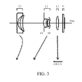
- FIG. 3 is an optical sectional view of an optical system according to a second embodiment.
- FIGS. 4A and 4B are aberrational diagrams at a wide angle end and a telephoto end of the optical system according to the second embodiment.
- FIG. 5 is an optical sectional view of an optical system according to a third embodiment.
- FIGS. 6A and 6B are aberrational diagrams at a wide angle end and a telephoto end of the optical system according to the third embodiment.
- FIG. 7 is a view for explaining a principal part of an aperture diaphragm according to the present invention.
- FIGS. 8A and 8B are perspective views of a principal part of the aperture diaphragm according to the present invention.
- FIG. 9 is a schematic view of a principal part of an image pickup apparatus according to the present invention.
- the optical system according to the present invention includes an aperture diaphragm having a curved surface shape in which an aperture part is movable in the optical axis direction as the aperture diameter changes.
- the aperture diaphragm has a convex shape on the object side.
- the aperture diaphragm has a convex shape on the image side.
- FIG. 1 is a lens sectional view at a wide angle end (short focal length end) of the zoom lens according to the first embodiment of the present invention.
- FIGS. 2A and 2B are aberrational diagrams at a wide angle end and a telephoto end (long focal length end) of the zoom lens according to the first embodiment, respectively.
- FIG. 3 is a lens sectional view at a wide angle end of a zoom lens according to a second embodiment of the present invention.
- FIGS. 4A and 4B are aberrational diagrams at a wide angle end and a telephoto end of the zoom lens according to the second embodiment, respectively.
- FIG. 5 is a lens sectional view at a wide angle end of a zoom lens according to a third embodiment of the present invention.
- FIGS. 6A and 6B are aberrational diagrams at a wide angle end and a telephoto end of the zoom lens according to the third embodiment, respectively.
- FIG. 7 is a sectional view of a principal part of an aperture diaphragm according to the present invention.
- FIGS. 8A and 8B are perspective views of a principal part of the aperture diaphragm according to the present invention.
- FIG. 9 is a perspective view of a principal part of the image pickup apparatus that includes the optical system according to the present invention.
- the zoom lenses according to the first to third embodiments are image pickup optical systems used for the image pickup apparatus.
- a left side is an object side (front side), and a right side is an image side (backside) in the lens sectional view.
- L 1 denotes a first lens unit having a positive refractive power (optical power is a reciprocal of a focal length)
- L 2 denotes a second lens unit having a negative refractive power
- L 3 denotes a third lens unit having a positive refractive power
- L 4 denotes a fourth lens unit having a positive refractive power.
- SP denotes an F-number determining diaphragm (aperture diaphragm) configured to restrict a maximum aperture F-number light flux.
- the aperture diaphragm SP is arranged on the object side of the third lens unit L 3 .
- FS denotes a flare cutting diaphragm having a constant aperture diameter.
- G denotes an optical block, such as an optical filter and a face plate.
- 1 mg denotes an image plane, corresponding to an image pickup plane of a solid state image sensor, such as a CCD sensor and a CMOS sensors (photoelectrical conversion element), when it is used as an image pickup optical system for a video camera and a digital camera. It corresponds to a film plane when it is used as an image pickup optical system for a film-based camera.
- each lens unit is moved as illustrated by arrows in zooming from the wide angle end to the telephoto end. More specifically, the first lens unit L 1 moves to the object side after it moves to the image side. The second lens unit L 2 moves to the object side with a concave locus. The third lens unit L 3 moves to the object side together with the aperture diaphragm SP and the flare cutting diaphragm FP. The fourth lens unit L 4 moves to the object side with a convex locus so as to correct an image plane fluctuation associated with the magnification variation. The fourth lens unit L 4 is moved to the object side for focusing from an infinite object to a short distance object.
- L 1 denotes a first lens unit having a negative refractive power
- L 2 denotes a second lens unit having a positive refractive power
- L 3 is a third lens unit having a positive refractive power
- SP denotes an aperture diaphragm arranged on the image side of the second lens unit L 2
- FS denotes a flare cutting diaphragm.
- the flare cutting diaphragm FS is arranged between a vertex on the object side of a positive lens that is closest to the object side in the second lens unit L 2 in the optical axis direction and an intersection between the lens surface on the object side of the positive lens and the outer circumferential part (lens end surface).
- G denotes an optical block.
- Img denotes an image plane.
- the first lens unit L 1 in zooming from the wide angle end to the telephoto end, the first lens unit L 1 approximately reciprocates with a convex locus on the image side and corrects an image plane variation associated with the magnification variation.
- the second lens unit L 2 monotonously moves to the object side for a main magnification variation.
- the aperture diaphragm SP and the flare cutting diaphragm FS move with the second lens unit L 2 .
- the third lens unit L 3 moves to the image side.
- an interval between the first lens unit L 1 and the second lens unit L 2 decreases, and an interval between the second lens unit L 2 and the third lens unit L 3 increases.
- the third lens unit L 3 is moved to the object side for focusing from the infinite object to the short distance object.
- the zoom type according to the third embodiment illustrated in FIG. 5 is the same as that of the second embodiment.
- the third embodiment is different from the second embodiment in that the aperture diaphragm SP is arranged between the first lens unit L 1 and the second lens unit L 2 , and moves to the object side in zooming with a locus different from that of another lens unit.
- Another difference is that the flare cutting diaphragm FS is arranged on the image side of the second lens unit L 2 , and moves with the second lens unit L 2 in zooming.
- the synthesized refractive power of the lens units on the object side of the aperture diaphragm SP is negative, and the aperture diaphragm SP has a convex shape on the object side.
- the synthesized refractive power of the lens units on the object side of the aperture diaphragm is positive, and the aperture diaphragm SP has a convex shape on the image side.
- the aperture diaphragm SP having a shape determined by each embodiment provides a wide angle of field, a high zoom ratio, a compact overall system, and a high image quality.
- the third lens unit L 3 is partially or wholly moved with a component perpendicular to the optical axis for the image stabilization when an imaging position is moved perpendicular to the optical axis and the optical system oscillates.
- second lens unit L 2 is partially or wholly moved with a component perpendicular to the optical axis so as to move the imaging position in the direction perpendicular to the optical axis.
- the lens unit closest to the image side is moved along the optical axis for focusing. This configuration restrains the weight of the lens unit that moves for focusing and realizes high-speed focusing.
- Fno denotes an F-number
- ⁇ denotes half an angle of field (degree) of the image pickup angle of field.
- d-line solid line
- g-line dotted line
- a meridional image plane ⁇ M and a sagittal image plane ⁇ S for the d-line are illustrated.
- the d-line is illustrated.
- the lateral chromatic aberration the aberration of the g-line to the d-line is illustrated.
- the wide angle end and the telephoto end represent an arrangement of each lens unit in a minimum focal length and an arrangement of each lens unit in a maximum focal length.
- An arrow indicates a locus of each lens unit in zooming from the wide angle end to the telephoto end, and a locus of each lens unit in focusing from the infinite object to the short distance object.
- a diaphragm distance represents a distance in the optical axis direction from an axial position Spa of the aperture part of the aperture diaphragm SP to a surface vertex Ga on the object side of a lens LG on the image side of the aperture diaphragm SP.
- D 1 denotes a diaphragm distance when the aperture diameter of the aperture diaphragm SP is ⁇ 1
- D 2 denotes a diaphragm distance when the aperture diameter of the aperture diaphragm SP is ⁇ 2
- fF denotes a synthesized focal length of the optical system arranged on the object side of the aperture diaphragm SP.
- each embodiment moves the axial position (the position on the optical axis) of the aperture part of the aperture diaphragm SP to a divergence side of the axial light flux that passes the aperture diaphragm SP.
- the aperture diameter becomes larger than that when the axial position of the aperture part of the aperture diaphragm SP does not change, and sufficiently large light amount at a periphery of an image can be secured.
- each embodiment moves the axial position of the aperture part of the aperture diaphragm SP to a convergence side of the axial light flux that passes the aperture diaphragm SP.
- the aperture diameter becomes smaller than that when the axial position of the aperture part of the aperture diaphragm SP does not change, a flare component of the off-axis light can be effectively prevented and the image quality can be improved.
- This configuration can provide an optical system and an image pickup apparatus with a wide angle of view, a high zoom ratio, a compact overall system, and high image quality.
- the conditional expression (1) specifies a preferable ratio of a distances from the aperture diaphragm SP to the vertex Ga on the object side of the lens LG on the image side of the aperture diaphragm SP in a plurality of diaphragm diameters of the aperture diaphragm SP.
- It defines an axial moving direction of the aperture part when the aperture diameter of the aperture diaphragm SP is changed according to the refractive power of the optical system (whether the axial light flux incident upon the aperture diaphragm SP is a divergent light flux or a convergent light flux) arranged on the object side of the aperture diaphragm SP.
- the aperture diaphragm SP When the optical system placed on the object side of the aperture diaphragm SP has a negative refractive power (as in the first and third embodiments in FIGS. 1 and 5 ), the aperture diaphragm SP is arranged with its convex shape on the object side. On the other hand, when the optical system placed on the object side of the aperture diaphragm SP has a positive refractive power (as in the second embodiment in FIG. 3 ) the aperture diaphragm SP is arranged with its convex shape on the image side.
- the partial system that includes the first lens unit L 1 and the second lens unit L 2 has a negative refractive power in the overall zoom range, and the aperture blade of the aperture diaphragm SP has a convex shape on the object side.
- the partial system that includes the first lens unit L 1 and the second lens unit L 2 has a positive refractive power in the overall zoom range, and the aperture blade of the aperture diaphragm SP has a convex shape on the image side.
- the first lens unit L 1 has a negative refractive power, and thus the aperture blade of the aperture diaphragm SP has a convex shape on the object side.
- conditional expression (1) may be set as follows: 0.010 ⁇ fF *( D 1 ⁇ D 2)/
- the aperture diaphragm SP may have an area in which a diaphragm distance D continuously changes when the aperture diameter ⁇ of the aperture diaphragm is continuously changed.
- the aperture diameter ⁇ continuously changes in the motion image pickup, the light amount at a periphery of an image steeply changes unless the diaphragm distance D continues due to switching of the function of the aperture diaphragm to another material such as sheet metal, by the aperture diameter ⁇ .
- the diaphragm distance D of the aperture diaphragm by continuously changing the diaphragm distance D of the aperture diaphragm, light amount at a periphery of an image can be moderately changed and the brightness drop at a periphery of an image can be prevented from standing out.
- a curved surface shape of the aperture blade is suitable for the shape of the aperture diaphragm according to this embodiment.
- This configuration can easily obtain an effect of each embodiment since the diaphragm distance of the aperture diaphragm can be more greatly changed for a large aperture diameter with which it is difficult to secure the light amount at a periphery of an image.
- the optical system retracts in the non-image pickup state, and the following conditional expression may be satisfied where ⁇ off denotes an aperture diameter of the aperture diaphragm SP in the retraction housing state and ⁇ min denotes a minimum value of an aperture diameter of the aperture diaphragm SP in the image pickup state: ⁇ min ⁇ off (2)
- a lens unit interval can be as small as possible in the non-image pickup state and the housing performance can be enhanced.
- the aperture blade can be closer to the lens next to the diaphragm in the non-image pickup state than in the image pickup state. Hence, the miniaturization can be realized by narrowing the lens unit intervals in the retraction.
- the optical system may satisfy the following conditional expression where ⁇ max is a maximum value of the aperture diameter of the aperture diaphragm SP in the image pickup state: ⁇ max ⁇ off (3)
- the miniaturization can be realized by narrowing the lens unit intervals in the retraction because this configuration can arrange the aperture blade outside the lens diameter or the light effective diameter of the lens near the aperture diaphragm SP at the non-image pickup time.
- the optical system may have a zoom unit configured to provide zooming by moving two or more lens units. When the optical system moves two or more lens units for zooming, the diaphragm configuration can minimize the interval between the lens units, increase a moving amount of each lens unit and, easily provide a miniaturization and a high zoom ratio.
- FIGS. 8A and 8B are schematic diagrams of a principal part of an iris diaphragm unit (aperture diaphragm unit) used for the optical system according to the present invention.
- FIG. 8A illustrates the aperture diaphragm having a small aperture diameter
- FIG. 8B illustrates the aperture diaphragm having a large aperture diameter.
- Reference numeral 1 denotes an aperture blade having a curved surface shape in FIGS. 8A and 8B , and an aperture diameter of the diaphragm and a position of the aperture diaphragm SP can be changed by rotating the aperture blade around the optical axis utilizing a motor (driver).
- reference numeral 10 denotes a camera body.
- Reference numeral 11 denotes an image pickup optical system that includes one of the optical systems according to the first to third embodiments.
- Reference numeral 12 denotes a solid state image sensor (photoelectric conversion element), such as a CCD sensor and a CMOS sensor, configured to receive light of an object image formed by the image pickup optical system 11 .
- Reference numeral 13 is a recorder configured to record the object image received by the image pickup element 12 .
- Reference numeral 14 denotes a viewfinder configured to observe the object image displayed on the display element (not illustrated).
- the display element includes a liquid display panel, etc., and to display the object image formed on the image pickup element 12 .
- An aspheric shape X is expressed by a displacement in the optical axis direction of the position having a height H from the optical axis.
- the light traveling direction is set to positive.
- R denotes a paraxial radius of curvature
- k denotes a conic constant
- A4, A6, A8, A10, A12, and A14 are aspheric coefficients, and the following expression is established:
Landscapes
- Physics & Mathematics (AREA)
- General Physics & Mathematics (AREA)
- Optics & Photonics (AREA)
- Nonlinear Science (AREA)
- Lenses (AREA)
- Diaphragms For Cameras (AREA)
Applications Claiming Priority (2)
| Application Number | Priority Date | Filing Date | Title |
|---|---|---|---|
| JP2012-108475 | 2012-05-10 | ||
| JP2012108475A JP2013235183A (ja) | 2012-05-10 | 2012-05-10 | 光学系及びそれを有する撮像装置 |
Publications (2)
| Publication Number | Publication Date |
|---|---|
| US20130300913A1 US20130300913A1 (en) | 2013-11-14 |
| US8891180B2 true US8891180B2 (en) | 2014-11-18 |
Family
ID=49548329
Family Applications (1)
| Application Number | Title | Priority Date | Filing Date |
|---|---|---|---|
| US13/875,786 Active US8891180B2 (en) | 2012-05-10 | 2013-05-02 | Optical system, and image pickup apparatus having the same |
Country Status (2)
| Country | Link |
|---|---|
| US (1) | US8891180B2 (enExample) |
| JP (1) | JP2013235183A (enExample) |
Cited By (1)
| Publication number | Priority date | Publication date | Assignee | Title |
|---|---|---|---|---|
| US10571651B2 (en) | 2016-12-27 | 2020-02-25 | Canon Kabushiki Kaisha | Image pickup optical system, image pickup apparatus having the image pickup optical system, lens apparatus having the image pickup optical system, and image pickup system having the image pickup optical system |
Families Citing this family (6)
| Publication number | Priority date | Publication date | Assignee | Title |
|---|---|---|---|---|
| JP6270475B2 (ja) * | 2011-07-07 | 2018-01-31 | キヤノン電子株式会社 | 光量調節装置および光学機器 |
| JP6039332B2 (ja) * | 2012-09-21 | 2016-12-07 | キヤノン株式会社 | ズームレンズ及びそれを有する撮像装置 |
| JP6071396B2 (ja) * | 2012-10-04 | 2017-02-01 | キヤノン株式会社 | 光学機器 |
| JP6425028B2 (ja) * | 2015-04-15 | 2018-11-21 | コニカミノルタ株式会社 | 撮像レンズ、レンズユニット、撮像装置、デジタルスチルカメラ及び携帯端末 |
| KR101777661B1 (ko) * | 2016-09-20 | 2017-09-13 | 주식회사 소모에너지엔테크놀러지 | 수평화각 21도의 장파장 적외선 카메라 및 카메라용 렌즈 |
| KR101768575B1 (ko) * | 2016-09-20 | 2017-08-17 | 주식회사 소모에너지엔테크놀러지 | 수평화각 54도의 장파장 적외선 카메라 및 카메라용 렌즈 |
Citations (5)
| Publication number | Priority date | Publication date | Assignee | Title |
|---|---|---|---|---|
| US7023623B2 (en) | 2002-04-11 | 2006-04-04 | Matsushita Electric Industrial Co., Ltd. | Zoom lens and electronic still camera using the same |
| JP2007094074A (ja) | 2005-09-29 | 2007-04-12 | Canon Inc | 光量調節装置、レンズ鏡筒および撮像装置 |
| JP2010164606A (ja) | 2009-01-13 | 2010-07-29 | Olympus Imaging Corp | ズームレンズ及びそれを用いた撮像装置 |
| US7830613B2 (en) | 2008-06-20 | 2010-11-09 | Olympus Imaging Corp. | Zoom lens and an imaging apparatus incorporating the same |
| US8009343B2 (en) * | 2003-08-01 | 2011-08-30 | Carl Zeiss Smt Gmbh | Optical imaging device having at least one system diaphragm |
Family Cites Families (3)
| Publication number | Priority date | Publication date | Assignee | Title |
|---|---|---|---|---|
| JP3676518B2 (ja) * | 1996-10-07 | 2005-07-27 | オリンパス株式会社 | カメラの可変絞り機構付きレンズ鏡枠 |
| JP2001281545A (ja) * | 1999-10-06 | 2001-10-10 | Canon Inc | ズームレンズ及びそれを用いた光学機器 |
| JP5015202B2 (ja) * | 2009-06-30 | 2012-08-29 | Hoya株式会社 | 可変開口絞機構を備えたズームレンズ鏡筒 |
-
2012
- 2012-05-10 JP JP2012108475A patent/JP2013235183A/ja active Pending
-
2013
- 2013-05-02 US US13/875,786 patent/US8891180B2/en active Active
Patent Citations (6)
| Publication number | Priority date | Publication date | Assignee | Title |
|---|---|---|---|---|
| US7023623B2 (en) | 2002-04-11 | 2006-04-04 | Matsushita Electric Industrial Co., Ltd. | Zoom lens and electronic still camera using the same |
| JP2008250332A (ja) | 2002-04-11 | 2008-10-16 | Matsushita Electric Ind Co Ltd | ズームレンズ及びそれを用いた電子スチルカメラ |
| US8009343B2 (en) * | 2003-08-01 | 2011-08-30 | Carl Zeiss Smt Gmbh | Optical imaging device having at least one system diaphragm |
| JP2007094074A (ja) | 2005-09-29 | 2007-04-12 | Canon Inc | 光量調節装置、レンズ鏡筒および撮像装置 |
| US7830613B2 (en) | 2008-06-20 | 2010-11-09 | Olympus Imaging Corp. | Zoom lens and an imaging apparatus incorporating the same |
| JP2010164606A (ja) | 2009-01-13 | 2010-07-29 | Olympus Imaging Corp | ズームレンズ及びそれを用いた撮像装置 |
Cited By (1)
| Publication number | Priority date | Publication date | Assignee | Title |
|---|---|---|---|---|
| US10571651B2 (en) | 2016-12-27 | 2020-02-25 | Canon Kabushiki Kaisha | Image pickup optical system, image pickup apparatus having the image pickup optical system, lens apparatus having the image pickup optical system, and image pickup system having the image pickup optical system |
Also Published As
| Publication number | Publication date |
|---|---|
| US20130300913A1 (en) | 2013-11-14 |
| JP2013235183A (ja) | 2013-11-21 |
Similar Documents
| Publication | Publication Date | Title |
|---|---|---|
| US9753262B2 (en) | Zoom lens and imaging apparatus having the same | |
| US8988588B2 (en) | Zoom lens and image pickup apparatus including the same | |
| US9268120B2 (en) | Zoom lens and image pickup apparatus including the same | |
| US9268118B2 (en) | Zoom lens and image-pickup apparatus | |
| US9684155B2 (en) | Optical system and image pickup apparatus including the same | |
| US8179608B2 (en) | Zoom lens and image pickup apparatus including the same | |
| US7995286B2 (en) | Zoom lens and image pickup apparatus including the same | |
| US9207438B2 (en) | Zoom lens and image pick-up apparatus having the same | |
| US9297985B2 (en) | Zoom lens and image-pickup apparatus | |
| US11194137B2 (en) | Zoom lens and image pickup apparatus including same | |
| US8891180B2 (en) | Optical system, and image pickup apparatus having the same | |
| US8792181B2 (en) | Zoom lens and image pickup apparatus including the same | |
| US9557544B2 (en) | Zoom lens and image pickup apparatus including zoom lens | |
| US8159758B2 (en) | Zoom lens system and image pickup apparatus having same | |
| US8736973B2 (en) | Zoom lens and image pickup apparatus equipped with zoom lens | |
| US20130162885A1 (en) | Zoom lens and image pickup apparatus having the same | |
| US8649106B2 (en) | Zoom lens and image pickup apparatus equipped with the zoom lens | |
| US20150226930A1 (en) | Optical system and optical device provided therewith | |
| JP4411010B2 (ja) | ズームレンズ及びそれを用いた撮像機器 | |
| US8861093B2 (en) | Zoom lens and image pickup apparatus equipped with the same | |
| US11073741B2 (en) | Zoom lens and optical apparatus | |
| US20140334012A1 (en) | Zoom lens, optical apparatus, and method for manufacturing the zoom lens | |
| US20140204264A1 (en) | Zoom lens and image pickup apparatus including the same | |
| US9372327B2 (en) | Zoom lens and image-pickup apparatus having the same | |
| JP2005316182A (ja) | ズームレンズ及びそれを有する撮像装置 |
Legal Events
| Date | Code | Title | Description |
|---|---|---|---|
| AS | Assignment |
Owner name: CANON KABUSHIKI KAISHA, JAPAN Free format text: ASSIGNMENT OF ASSIGNORS INTEREST;ASSIGNOR:SAKAI, HIDEKI;REEL/FRAME:031086/0441 Effective date: 20130424 |
|
| STCF | Information on status: patent grant |
Free format text: PATENTED CASE |
|
| MAFP | Maintenance fee payment |
Free format text: PAYMENT OF MAINTENANCE FEE, 4TH YEAR, LARGE ENTITY (ORIGINAL EVENT CODE: M1551) Year of fee payment: 4 |
|
| MAFP | Maintenance fee payment |
Free format text: PAYMENT OF MAINTENANCE FEE, 8TH YEAR, LARGE ENTITY (ORIGINAL EVENT CODE: M1552); ENTITY STATUS OF PATENT OWNER: LARGE ENTITY Year of fee payment: 8 |