US8883291B2 - Metal oxide coating on surfaces - Google Patents
Metal oxide coating on surfaces Download PDFInfo
- Publication number
- US8883291B2 US8883291B2 US12/733,086 US73308608A US8883291B2 US 8883291 B2 US8883291 B2 US 8883291B2 US 73308608 A US73308608 A US 73308608A US 8883291 B2 US8883291 B2 US 8883291B2
- Authority
- US
- United States
- Prior art keywords
- pdms
- metal oxide
- preconverted
- channels
- microfluidic device
- Prior art date
- Legal status (The legal status is an assumption and is not a legal conclusion. Google has not performed a legal analysis and makes no representation as to the accuracy of the status listed.)
- Expired - Fee Related, expires
Links
- 238000000576 coating method Methods 0.000 title claims abstract description 91
- 229910044991 metal oxide Inorganic materials 0.000 title claims abstract description 72
- 150000004706 metal oxides Chemical class 0.000 title claims abstract description 72
- 239000011248 coating agent Substances 0.000 title claims abstract description 71
- 229920000435 poly(dimethylsiloxane) Polymers 0.000 claims abstract description 169
- 239000004205 dimethyl polysiloxane Substances 0.000 claims abstract description 167
- 235000013870 dimethyl polysiloxane Nutrition 0.000 claims abstract 9
- CXQXSVUQTKDNFP-UHFFFAOYSA-N octamethyltrisiloxane Chemical compound C[Si](C)(C)O[Si](C)(C)O[Si](C)(C)C CXQXSVUQTKDNFP-UHFFFAOYSA-N 0.000 claims abstract 9
- 238000004987 plasma desorption mass spectroscopy Methods 0.000 claims abstract 9
- VYPSYNLAJGMNEJ-UHFFFAOYSA-N Silicium dioxide Chemical compound O=[Si]=O VYPSYNLAJGMNEJ-UHFFFAOYSA-N 0.000 claims description 59
- 239000000377 silicon dioxide Substances 0.000 claims description 29
- XEEYBQQBJWHFJM-UHFFFAOYSA-N Iron Chemical compound [Fe] XEEYBQQBJWHFJM-UHFFFAOYSA-N 0.000 claims description 6
- PXHVJJICTQNCMI-UHFFFAOYSA-N Nickel Chemical compound [Ni] PXHVJJICTQNCMI-UHFFFAOYSA-N 0.000 claims description 6
- KDLHZDBZIXYQEI-UHFFFAOYSA-N Palladium Chemical compound [Pd] KDLHZDBZIXYQEI-UHFFFAOYSA-N 0.000 claims description 6
- 229910052751 metal Inorganic materials 0.000 claims description 5
- 239000002184 metal Substances 0.000 claims description 5
- OYPRJOBELJOOCE-UHFFFAOYSA-N Calcium Chemical compound [Ca] OYPRJOBELJOOCE-UHFFFAOYSA-N 0.000 claims description 3
- 229910052684 Cerium Inorganic materials 0.000 claims description 3
- VYZAMTAEIAYCRO-UHFFFAOYSA-N Chromium Chemical compound [Cr] VYZAMTAEIAYCRO-UHFFFAOYSA-N 0.000 claims description 3
- RYGMFSIKBFXOCR-UHFFFAOYSA-N Copper Chemical compound [Cu] RYGMFSIKBFXOCR-UHFFFAOYSA-N 0.000 claims description 3
- 229910052692 Dysprosium Inorganic materials 0.000 claims description 3
- 229910052691 Erbium Inorganic materials 0.000 claims description 3
- 229910052688 Gadolinium Inorganic materials 0.000 claims description 3
- 229910052689 Holmium Inorganic materials 0.000 claims description 3
- DGAQECJNVWCQMB-PUAWFVPOSA-M Ilexoside XXIX Chemical compound C[C@@H]1CC[C@@]2(CC[C@@]3(C(=CC[C@H]4[C@]3(CC[C@@H]5[C@@]4(CC[C@@H](C5(C)C)OS(=O)(=O)[O-])C)C)[C@@H]2[C@]1(C)O)C)C(=O)O[C@H]6[C@@H]([C@H]([C@@H]([C@H](O6)CO)O)O)O.[Na+] DGAQECJNVWCQMB-PUAWFVPOSA-M 0.000 claims description 3
- WHXSMMKQMYFTQS-UHFFFAOYSA-N Lithium Chemical compound [Li] WHXSMMKQMYFTQS-UHFFFAOYSA-N 0.000 claims description 3
- 229910052765 Lutetium Inorganic materials 0.000 claims description 3
- FYYHWMGAXLPEAU-UHFFFAOYSA-N Magnesium Chemical compound [Mg] FYYHWMGAXLPEAU-UHFFFAOYSA-N 0.000 claims description 3
- ZOKXTWBITQBERF-UHFFFAOYSA-N Molybdenum Chemical compound [Mo] ZOKXTWBITQBERF-UHFFFAOYSA-N 0.000 claims description 3
- 229910052779 Neodymium Inorganic materials 0.000 claims description 3
- ZLMJMSJWJFRBEC-UHFFFAOYSA-N Potassium Chemical compound [K] ZLMJMSJWJFRBEC-UHFFFAOYSA-N 0.000 claims description 3
- 229910052777 Praseodymium Inorganic materials 0.000 claims description 3
- KJTLSVCANCCWHF-UHFFFAOYSA-N Ruthenium Chemical compound [Ru] KJTLSVCANCCWHF-UHFFFAOYSA-N 0.000 claims description 3
- 229910052772 Samarium Inorganic materials 0.000 claims description 3
- XUIMIQQOPSSXEZ-UHFFFAOYSA-N Silicon Chemical compound [Si] XUIMIQQOPSSXEZ-UHFFFAOYSA-N 0.000 claims description 3
- BQCADISMDOOEFD-UHFFFAOYSA-N Silver Chemical compound [Ag] BQCADISMDOOEFD-UHFFFAOYSA-N 0.000 claims description 3
- 229910052771 Terbium Inorganic materials 0.000 claims description 3
- ATJFFYVFTNAWJD-UHFFFAOYSA-N Tin Chemical compound [Sn] ATJFFYVFTNAWJD-UHFFFAOYSA-N 0.000 claims description 3
- RTAQQCXQSZGOHL-UHFFFAOYSA-N Titanium Chemical compound [Ti] RTAQQCXQSZGOHL-UHFFFAOYSA-N 0.000 claims description 3
- 229910052769 Ytterbium Inorganic materials 0.000 claims description 3
- QCWXUUIWCKQGHC-UHFFFAOYSA-N Zirconium Chemical compound [Zr] QCWXUUIWCKQGHC-UHFFFAOYSA-N 0.000 claims description 3
- 229910052782 aluminium Inorganic materials 0.000 claims description 3
- XAGFODPZIPBFFR-UHFFFAOYSA-N aluminium Chemical compound [Al] XAGFODPZIPBFFR-UHFFFAOYSA-N 0.000 claims description 3
- 229910052787 antimony Inorganic materials 0.000 claims description 3
- WATWJIUSRGPENY-UHFFFAOYSA-N antimony atom Chemical compound [Sb] WATWJIUSRGPENY-UHFFFAOYSA-N 0.000 claims description 3
- 229910052788 barium Inorganic materials 0.000 claims description 3
- DSAJWYNOEDNPEQ-UHFFFAOYSA-N barium atom Chemical compound [Ba] DSAJWYNOEDNPEQ-UHFFFAOYSA-N 0.000 claims description 3
- 229910052797 bismuth Inorganic materials 0.000 claims description 3
- JCXGWMGPZLAOME-UHFFFAOYSA-N bismuth atom Chemical compound [Bi] JCXGWMGPZLAOME-UHFFFAOYSA-N 0.000 claims description 3
- 229910052793 cadmium Inorganic materials 0.000 claims description 3
- BDOSMKKIYDKNTQ-UHFFFAOYSA-N cadmium atom Chemical compound [Cd] BDOSMKKIYDKNTQ-UHFFFAOYSA-N 0.000 claims description 3
- 229910052792 caesium Inorganic materials 0.000 claims description 3
- TVFDJXOCXUVLDH-UHFFFAOYSA-N caesium atom Chemical compound [Cs] TVFDJXOCXUVLDH-UHFFFAOYSA-N 0.000 claims description 3
- 229910052791 calcium Inorganic materials 0.000 claims description 3
- 239000011575 calcium Substances 0.000 claims description 3
- 229910052804 chromium Inorganic materials 0.000 claims description 3
- 239000011651 chromium Substances 0.000 claims description 3
- 229910017052 cobalt Inorganic materials 0.000 claims description 3
- 239000010941 cobalt Substances 0.000 claims description 3
- GUTLYIVDDKVIGB-UHFFFAOYSA-N cobalt atom Chemical compound [Co] GUTLYIVDDKVIGB-UHFFFAOYSA-N 0.000 claims description 3
- 229910052802 copper Inorganic materials 0.000 claims description 3
- 239000010949 copper Substances 0.000 claims description 3
- KBQHZAAAGSGFKK-UHFFFAOYSA-N dysprosium atom Chemical compound [Dy] KBQHZAAAGSGFKK-UHFFFAOYSA-N 0.000 claims description 3
- UYAHIZSMUZPPFV-UHFFFAOYSA-N erbium Chemical compound [Er] UYAHIZSMUZPPFV-UHFFFAOYSA-N 0.000 claims description 3
- UIWYJDYFSGRHKR-UHFFFAOYSA-N gadolinium atom Chemical compound [Gd] UIWYJDYFSGRHKR-UHFFFAOYSA-N 0.000 claims description 3
- 229910052732 germanium Inorganic materials 0.000 claims description 3
- GNPVGFCGXDBREM-UHFFFAOYSA-N germanium atom Chemical compound [Ge] GNPVGFCGXDBREM-UHFFFAOYSA-N 0.000 claims description 3
- 229910052735 hafnium Inorganic materials 0.000 claims description 3
- VBJZVLUMGGDVMO-UHFFFAOYSA-N hafnium atom Chemical compound [Hf] VBJZVLUMGGDVMO-UHFFFAOYSA-N 0.000 claims description 3
- KJZYNXUDTRRSPN-UHFFFAOYSA-N holmium atom Chemical compound [Ho] KJZYNXUDTRRSPN-UHFFFAOYSA-N 0.000 claims description 3
- 229910052738 indium Inorganic materials 0.000 claims description 3
- APFVFJFRJDLVQX-UHFFFAOYSA-N indium atom Chemical compound [In] APFVFJFRJDLVQX-UHFFFAOYSA-N 0.000 claims description 3
- 229910052741 iridium Inorganic materials 0.000 claims description 3
- GKOZUEZYRPOHIO-UHFFFAOYSA-N iridium atom Chemical compound [Ir] GKOZUEZYRPOHIO-UHFFFAOYSA-N 0.000 claims description 3
- 229910052742 iron Inorganic materials 0.000 claims description 3
- 229910052746 lanthanum Inorganic materials 0.000 claims description 3
- FZLIPJUXYLNCLC-UHFFFAOYSA-N lanthanum atom Chemical compound [La] FZLIPJUXYLNCLC-UHFFFAOYSA-N 0.000 claims description 3
- 229910052744 lithium Inorganic materials 0.000 claims description 3
- OHSVLFRHMCKCQY-UHFFFAOYSA-N lutetium atom Chemical compound [Lu] OHSVLFRHMCKCQY-UHFFFAOYSA-N 0.000 claims description 3
- 229910052749 magnesium Inorganic materials 0.000 claims description 3
- 239000011777 magnesium Substances 0.000 claims description 3
- WPBNNNQJVZRUHP-UHFFFAOYSA-L manganese(2+);methyl n-[[2-(methoxycarbonylcarbamothioylamino)phenyl]carbamothioyl]carbamate;n-[2-(sulfidocarbothioylamino)ethyl]carbamodithioate Chemical compound [Mn+2].[S-]C(=S)NCCNC([S-])=S.COC(=O)NC(=S)NC1=CC=CC=C1NC(=S)NC(=O)OC WPBNNNQJVZRUHP-UHFFFAOYSA-L 0.000 claims description 3
- 229910052750 molybdenum Inorganic materials 0.000 claims description 3
- 239000011733 molybdenum Substances 0.000 claims description 3
- QEFYFXOXNSNQGX-UHFFFAOYSA-N neodymium atom Chemical compound [Nd] QEFYFXOXNSNQGX-UHFFFAOYSA-N 0.000 claims description 3
- 229910052759 nickel Inorganic materials 0.000 claims description 3
- 229910052758 niobium Inorganic materials 0.000 claims description 3
- 239000010955 niobium Substances 0.000 claims description 3
- GUCVJGMIXFAOAE-UHFFFAOYSA-N niobium atom Chemical compound [Nb] GUCVJGMIXFAOAE-UHFFFAOYSA-N 0.000 claims description 3
- 229910052763 palladium Inorganic materials 0.000 claims description 3
- 229910052700 potassium Inorganic materials 0.000 claims description 3
- 239000011591 potassium Substances 0.000 claims description 3
- PUDIUYLPXJFUGB-UHFFFAOYSA-N praseodymium atom Chemical compound [Pr] PUDIUYLPXJFUGB-UHFFFAOYSA-N 0.000 claims description 3
- 229910052703 rhodium Inorganic materials 0.000 claims description 3
- 239000010948 rhodium Substances 0.000 claims description 3
- MHOVAHRLVXNVSD-UHFFFAOYSA-N rhodium atom Chemical compound [Rh] MHOVAHRLVXNVSD-UHFFFAOYSA-N 0.000 claims description 3
- 229910052701 rubidium Inorganic materials 0.000 claims description 3
- IGLNJRXAVVLDKE-UHFFFAOYSA-N rubidium atom Chemical compound [Rb] IGLNJRXAVVLDKE-UHFFFAOYSA-N 0.000 claims description 3
- 229910052707 ruthenium Inorganic materials 0.000 claims description 3
- KZUNJOHGWZRPMI-UHFFFAOYSA-N samarium atom Chemical compound [Sm] KZUNJOHGWZRPMI-UHFFFAOYSA-N 0.000 claims description 3
- 229910052706 scandium Inorganic materials 0.000 claims description 3
- SIXSYDAISGFNSX-UHFFFAOYSA-N scandium atom Chemical compound [Sc] SIXSYDAISGFNSX-UHFFFAOYSA-N 0.000 claims description 3
- 229910052710 silicon Inorganic materials 0.000 claims description 3
- 239000010703 silicon Substances 0.000 claims description 3
- 229910052709 silver Inorganic materials 0.000 claims description 3
- 239000004332 silver Substances 0.000 claims description 3
- 229910052708 sodium Inorganic materials 0.000 claims description 3
- 239000011734 sodium Substances 0.000 claims description 3
- 229910052712 strontium Inorganic materials 0.000 claims description 3
- CIOAGBVUUVVLOB-UHFFFAOYSA-N strontium atom Chemical compound [Sr] CIOAGBVUUVVLOB-UHFFFAOYSA-N 0.000 claims description 3
- 229910052715 tantalum Inorganic materials 0.000 claims description 3
- GUVRBAGPIYLISA-UHFFFAOYSA-N tantalum atom Chemical compound [Ta] GUVRBAGPIYLISA-UHFFFAOYSA-N 0.000 claims description 3
- GZCRRIHWUXGPOV-UHFFFAOYSA-N terbium atom Chemical compound [Tb] GZCRRIHWUXGPOV-UHFFFAOYSA-N 0.000 claims description 3
- 229910052716 thallium Inorganic materials 0.000 claims description 3
- BKVIYDNLLOSFOA-UHFFFAOYSA-N thallium Chemical compound [Tl] BKVIYDNLLOSFOA-UHFFFAOYSA-N 0.000 claims description 3
- 229910052718 tin Inorganic materials 0.000 claims description 3
- 239000011135 tin Substances 0.000 claims description 3
- 229910052719 titanium Inorganic materials 0.000 claims description 3
- 239000010936 titanium Substances 0.000 claims description 3
- WFKWXMTUELFFGS-UHFFFAOYSA-N tungsten Chemical compound [W] WFKWXMTUELFFGS-UHFFFAOYSA-N 0.000 claims description 3
- 229910052721 tungsten Inorganic materials 0.000 claims description 3
- 239000010937 tungsten Substances 0.000 claims description 3
- 229910052720 vanadium Inorganic materials 0.000 claims description 3
- NAWDYIZEMPQZHO-UHFFFAOYSA-N ytterbium Chemical compound [Yb] NAWDYIZEMPQZHO-UHFFFAOYSA-N 0.000 claims description 3
- 229910052727 yttrium Inorganic materials 0.000 claims description 3
- VWQVUPCCIRVNHF-UHFFFAOYSA-N yttrium atom Chemical compound [Y] VWQVUPCCIRVNHF-UHFFFAOYSA-N 0.000 claims description 3
- 229910052726 zirconium Inorganic materials 0.000 claims description 3
- GWXLDORMOJMVQZ-UHFFFAOYSA-N cerium Chemical compound [Ce] GWXLDORMOJMVQZ-UHFFFAOYSA-N 0.000 claims 2
- LEONUFNNVUYDNQ-UHFFFAOYSA-N vanadium atom Chemical compound [V] LEONUFNNVUYDNQ-UHFFFAOYSA-N 0.000 claims 2
- 239000012703 sol-gel precursor Substances 0.000 abstract description 43
- 238000000034 method Methods 0.000 abstract description 38
- 239000000203 mixture Substances 0.000 abstract description 35
- 239000002243 precursor Substances 0.000 description 94
- YXFVVABEGXRONW-UHFFFAOYSA-N Toluene Chemical compound CC1=CC=CC=C1 YXFVVABEGXRONW-UHFFFAOYSA-N 0.000 description 49
- 239000000463 material Substances 0.000 description 33
- 230000015572 biosynthetic process Effects 0.000 description 29
- 239000012530 fluid Substances 0.000 description 24
- LFQSCWFLJHTTHZ-UHFFFAOYSA-N Ethanol Chemical compound CCO LFQSCWFLJHTTHZ-UHFFFAOYSA-N 0.000 description 21
- 238000006243 chemical reaction Methods 0.000 description 19
- XLYOFNOQVPJJNP-UHFFFAOYSA-N water Substances O XLYOFNOQVPJJNP-UHFFFAOYSA-N 0.000 description 16
- VEXZGXHMUGYJMC-UHFFFAOYSA-N Hydrochloric acid Chemical compound Cl VEXZGXHMUGYJMC-UHFFFAOYSA-N 0.000 description 15
- 238000009792 diffusion process Methods 0.000 description 13
- 239000000839 emulsion Substances 0.000 description 11
- BOTDANWDWHJENH-UHFFFAOYSA-N Tetraethyl orthosilicate Chemical compound CCO[Si](OCC)(OCC)OCC BOTDANWDWHJENH-UHFFFAOYSA-N 0.000 description 10
- 239000003960 organic solvent Substances 0.000 description 10
- 239000011521 glass Substances 0.000 description 9
- 239000003921 oil Substances 0.000 description 9
- 239000002683 reaction inhibitor Substances 0.000 description 9
- 230000002209 hydrophobic effect Effects 0.000 description 8
- -1 polydimethylsiloxane Polymers 0.000 description 8
- QVGXLLKOCUKJST-UHFFFAOYSA-N atomic oxygen Chemical compound [O] QVGXLLKOCUKJST-UHFFFAOYSA-N 0.000 description 7
- 239000003054 catalyst Substances 0.000 description 7
- 239000001301 oxygen Substances 0.000 description 7
- 229910052760 oxygen Inorganic materials 0.000 description 7
- 239000002904 solvent Substances 0.000 description 7
- 230000008901 benefit Effects 0.000 description 6
- 239000003112 inhibitor Substances 0.000 description 6
- 239000007788 liquid Substances 0.000 description 6
- 230000004048 modification Effects 0.000 description 6
- 238000012986 modification Methods 0.000 description 6
- 238000009832 plasma treatment Methods 0.000 description 6
- PYWVYCXTNDRMGF-UHFFFAOYSA-N rhodamine B Chemical compound [Cl-].C=12C=CC(=[N+](CC)CC)C=C2OC2=CC(N(CC)CC)=CC=C2C=1C1=CC=CC=C1C(O)=O PYWVYCXTNDRMGF-UHFFFAOYSA-N 0.000 description 6
- 229940043267 rhodamine b Drugs 0.000 description 6
- 238000002174 soft lithography Methods 0.000 description 6
- 239000000758 substrate Substances 0.000 description 6
- 230000008961 swelling Effects 0.000 description 6
- 238000004519 manufacturing process Methods 0.000 description 5
- 238000001000 micrograph Methods 0.000 description 5
- 125000005372 silanol group Chemical group 0.000 description 5
- 239000000126 substance Substances 0.000 description 5
- CPUDPFPXCZDNGI-UHFFFAOYSA-N triethoxy(methyl)silane Chemical compound CCO[Si](C)(OCC)OCC CPUDPFPXCZDNGI-UHFFFAOYSA-N 0.000 description 5
- 230000003993 interaction Effects 0.000 description 4
- 239000012702 metal oxide precursor Substances 0.000 description 4
- 229920000642 polymer Polymers 0.000 description 4
- 239000011347 resin Substances 0.000 description 4
- 229920005989 resin Polymers 0.000 description 4
- QTBSBXVTEAMEQO-UHFFFAOYSA-N Acetic acid Chemical compound CC(O)=O QTBSBXVTEAMEQO-UHFFFAOYSA-N 0.000 description 3
- OKKJLVBELUTLKV-UHFFFAOYSA-N Methanol Chemical compound OC OKKJLVBELUTLKV-UHFFFAOYSA-N 0.000 description 3
- MUBZPKHOEPUJKR-UHFFFAOYSA-N Oxalic acid Chemical compound OC(=O)C(O)=O MUBZPKHOEPUJKR-UHFFFAOYSA-N 0.000 description 3
- 230000009286 beneficial effect Effects 0.000 description 3
- 230000008859 change Effects 0.000 description 3
- 239000007809 chemical reaction catalyst Substances 0.000 description 3
- 238000000151 deposition Methods 0.000 description 3
- 230000008021 deposition Effects 0.000 description 3
- NBVXSUQYWXRMNV-UHFFFAOYSA-N fluoromethane Chemical compound FC NBVXSUQYWXRMNV-UHFFFAOYSA-N 0.000 description 3
- 125000000524 functional group Chemical group 0.000 description 3
- 238000002156 mixing Methods 0.000 description 3
- 239000002245 particle Substances 0.000 description 3
- 238000001179 sorption measurement Methods 0.000 description 3
- CURLTUGMZLYLDI-UHFFFAOYSA-N Carbon dioxide Chemical compound O=C=O CURLTUGMZLYLDI-UHFFFAOYSA-N 0.000 description 2
- MHAJPDPJQMAIIY-UHFFFAOYSA-N Hydrogen peroxide Chemical compound OO MHAJPDPJQMAIIY-UHFFFAOYSA-N 0.000 description 2
- KFZMGEQAYNKOFK-UHFFFAOYSA-N Isopropanol Chemical compound CC(C)O KFZMGEQAYNKOFK-UHFFFAOYSA-N 0.000 description 2
- NBIIXXVUZAFLBC-UHFFFAOYSA-N Phosphoric acid Chemical compound OP(O)(O)=O NBIIXXVUZAFLBC-UHFFFAOYSA-N 0.000 description 2
- 239000004698 Polyethylene Substances 0.000 description 2
- QAOWNCQODCNURD-UHFFFAOYSA-N Sulfuric acid Chemical compound OS(O)(=O)=O QAOWNCQODCNURD-UHFFFAOYSA-N 0.000 description 2
- 239000003377 acid catalyst Substances 0.000 description 2
- 150000001875 compounds Chemical class 0.000 description 2
- 238000009826 distribution Methods 0.000 description 2
- 238000007306 functionalization reaction Methods 0.000 description 2
- 230000007062 hydrolysis Effects 0.000 description 2
- 238000006460 hydrolysis reaction Methods 0.000 description 2
- 125000002887 hydroxy group Chemical group [H]O* 0.000 description 2
- 239000012535 impurity Substances 0.000 description 2
- 238000003754 machining Methods 0.000 description 2
- 229910052752 metalloid Inorganic materials 0.000 description 2
- 150000002738 metalloids Chemical class 0.000 description 2
- 150000002739 metals Chemical class 0.000 description 2
- 229920000573 polyethylene Polymers 0.000 description 2
- 230000035484 reaction time Effects 0.000 description 2
- 150000004756 silanes Chemical class 0.000 description 2
- 150000004819 silanols Chemical class 0.000 description 2
- 239000007787 solid Substances 0.000 description 2
- 241000894007 species Species 0.000 description 2
- 230000003075 superhydrophobic effect Effects 0.000 description 2
- VXUYXOFXAQZZMF-UHFFFAOYSA-N titanium(IV) isopropoxide Chemical compound CC(C)O[Ti](OC(C)C)(OC(C)C)OC(C)C VXUYXOFXAQZZMF-UHFFFAOYSA-N 0.000 description 2
- 238000009736 wetting Methods 0.000 description 2
- NGDLSKPZMOTRTR-OAPYJULQSA-N (4z)-4-heptadecylidene-3-hexadecyloxetan-2-one Chemical compound CCCCCCCCCCCCCCCC\C=C1/OC(=O)C1CCCCCCCCCCCCCCCC NGDLSKPZMOTRTR-OAPYJULQSA-N 0.000 description 1
- 241000252506 Characiformes Species 0.000 description 1
- PIICEJLVQHRZGT-UHFFFAOYSA-N Ethylenediamine Chemical compound NCCN PIICEJLVQHRZGT-UHFFFAOYSA-N 0.000 description 1
- GRYLNZFGIOXLOG-UHFFFAOYSA-N Nitric acid Chemical compound O[N+]([O-])=O GRYLNZFGIOXLOG-UHFFFAOYSA-N 0.000 description 1
- BLRPTPMANUNPDV-UHFFFAOYSA-N Silane Chemical compound [SiH4] BLRPTPMANUNPDV-UHFFFAOYSA-N 0.000 description 1
- RGJSWMPPIHQBPC-UHFFFAOYSA-N [V+5].CCCC[O-].CCCC[O-].CCCC[O-].CCCC[O-].CCCC[O-] Chemical compound [V+5].CCCC[O-].CCCC[O-].CCCC[O-].CCCC[O-].CCCC[O-] RGJSWMPPIHQBPC-UHFFFAOYSA-N 0.000 description 1
- 150000001242 acetic acid derivatives Chemical class 0.000 description 1
- 239000002253 acid Substances 0.000 description 1
- 150000007513 acids Chemical class 0.000 description 1
- 150000001298 alcohols Chemical class 0.000 description 1
- 150000004703 alkoxides Chemical class 0.000 description 1
- 150000001343 alkyl silanes Chemical class 0.000 description 1
- 229910000147 aluminium phosphate Inorganic materials 0.000 description 1
- 150000001413 amino acids Chemical class 0.000 description 1
- 230000004888 barrier function Effects 0.000 description 1
- 238000005251 capillar electrophoresis Methods 0.000 description 1
- 239000001569 carbon dioxide Substances 0.000 description 1
- 229910002092 carbon dioxide Inorganic materials 0.000 description 1
- 238000005266 casting Methods 0.000 description 1
- ZMIGMASIKSOYAM-UHFFFAOYSA-N cerium Chemical compound [Ce][Ce][Ce][Ce][Ce][Ce][Ce][Ce][Ce][Ce][Ce][Ce][Ce][Ce][Ce][Ce][Ce][Ce][Ce][Ce][Ce][Ce][Ce][Ce][Ce][Ce][Ce][Ce][Ce][Ce][Ce][Ce][Ce][Ce][Ce][Ce][Ce][Ce] ZMIGMASIKSOYAM-UHFFFAOYSA-N 0.000 description 1
- 230000000052 comparative effect Effects 0.000 description 1
- 239000006185 dispersion Substances 0.000 description 1
- 230000000694 effects Effects 0.000 description 1
- 239000007789 gas Substances 0.000 description 1
- 150000004820 halides Chemical class 0.000 description 1
- 239000001257 hydrogen Substances 0.000 description 1
- 229910052739 hydrogen Inorganic materials 0.000 description 1
- 150000002431 hydrogen Chemical class 0.000 description 1
- 238000010348 incorporation Methods 0.000 description 1
- 238000007373 indentation Methods 0.000 description 1
- 230000002452 interceptive effect Effects 0.000 description 1
- 230000001788 irregular Effects 0.000 description 1
- 150000002632 lipids Chemical class 0.000 description 1
- 238000005259 measurement Methods 0.000 description 1
- 239000012528 membrane Substances 0.000 description 1
- 230000005499 meniscus Effects 0.000 description 1
- ARYZCSRUUPFYMY-UHFFFAOYSA-N methoxysilane Chemical compound CO[SiH3] ARYZCSRUUPFYMY-UHFFFAOYSA-N 0.000 description 1
- 239000005055 methyl trichlorosilane Substances 0.000 description 1
- JLUFWMXJHAVVNN-UHFFFAOYSA-N methyltrichlorosilane Chemical compound C[Si](Cl)(Cl)Cl JLUFWMXJHAVVNN-UHFFFAOYSA-N 0.000 description 1
- 238000000813 microcontact printing Methods 0.000 description 1
- 238000001053 micromoulding Methods 0.000 description 1
- 238000001682 microtransfer moulding Methods 0.000 description 1
- 230000005012 migration Effects 0.000 description 1
- 238000013508 migration Methods 0.000 description 1
- 230000037230 mobility Effects 0.000 description 1
- 239000000178 monomer Substances 0.000 description 1
- 239000002090 nanochannel Substances 0.000 description 1
- 239000002105 nanoparticle Substances 0.000 description 1
- 150000002823 nitrates Chemical class 0.000 description 1
- 229910017604 nitric acid Inorganic materials 0.000 description 1
- 229910052756 noble gas Inorganic materials 0.000 description 1
- 150000002835 noble gases Chemical class 0.000 description 1
- 235000006408 oxalic acid Nutrition 0.000 description 1
- 230000003647 oxidation Effects 0.000 description 1
- 238000007254 oxidation reaction Methods 0.000 description 1
- 239000011148 porous material Substances 0.000 description 1
- 238000002360 preparation method Methods 0.000 description 1
- 230000002035 prolonged effect Effects 0.000 description 1
- 125000001436 propyl group Chemical group [H]C([*])([H])C([H])([H])C([H])([H])[H] 0.000 description 1
- 102000004169 proteins and genes Human genes 0.000 description 1
- 108090000623 proteins and genes Proteins 0.000 description 1
- 230000005855 radiation Effects 0.000 description 1
- 239000000376 reactant Substances 0.000 description 1
- 239000012713 reactive precursor Substances 0.000 description 1
- 230000009257 reactivity Effects 0.000 description 1
- 238000009877 rendering Methods 0.000 description 1
- 238000012552 review Methods 0.000 description 1
- 238000013341 scale-up Methods 0.000 description 1
- 238000012216 screening Methods 0.000 description 1
- 230000035945 sensitivity Effects 0.000 description 1
- 229910000077 silane Inorganic materials 0.000 description 1
- 229910052814 silicon oxide Inorganic materials 0.000 description 1
- 150000003384 small molecules Chemical class 0.000 description 1
- 238000004528 spin coating Methods 0.000 description 1
- 238000006467 substitution reaction Methods 0.000 description 1
- 238000004381 surface treatment Methods 0.000 description 1
- 238000003786 synthesis reaction Methods 0.000 description 1
- 238000012360 testing method Methods 0.000 description 1
- 229910052723 transition metal Inorganic materials 0.000 description 1
- 150000003624 transition metals Chemical class 0.000 description 1
- PYJJCSYBSYXGQQ-UHFFFAOYSA-N trichloro(octadecyl)silane Chemical class CCCCCCCCCCCCCCCCCC[Si](Cl)(Cl)Cl PYJJCSYBSYXGQQ-UHFFFAOYSA-N 0.000 description 1
- GPPXJZIENCGNKB-UHFFFAOYSA-N vanadium Chemical compound [V]#[V] GPPXJZIENCGNKB-UHFFFAOYSA-N 0.000 description 1
- 238000001039 wet etching Methods 0.000 description 1
Images


Classifications
-
- C—CHEMISTRY; METALLURGY
- C23—COATING METALLIC MATERIAL; COATING MATERIAL WITH METALLIC MATERIAL; CHEMICAL SURFACE TREATMENT; DIFFUSION TREATMENT OF METALLIC MATERIAL; COATING BY VACUUM EVAPORATION, BY SPUTTERING, BY ION IMPLANTATION OR BY CHEMICAL VAPOUR DEPOSITION, IN GENERAL; INHIBITING CORROSION OF METALLIC MATERIAL OR INCRUSTATION IN GENERAL
- C23C—COATING METALLIC MATERIAL; COATING MATERIAL WITH METALLIC MATERIAL; SURFACE TREATMENT OF METALLIC MATERIAL BY DIFFUSION INTO THE SURFACE, BY CHEMICAL CONVERSION OR SUBSTITUTION; COATING BY VACUUM EVAPORATION, BY SPUTTERING, BY ION IMPLANTATION OR BY CHEMICAL VAPOUR DEPOSITION, IN GENERAL
- C23C18/00—Chemical coating by decomposition of either liquid compounds or solutions of the coating forming compounds, without leaving reaction products of surface material in the coating; Contact plating
- C23C18/02—Chemical coating by decomposition of either liquid compounds or solutions of the coating forming compounds, without leaving reaction products of surface material in the coating; Contact plating by thermal decomposition
- C23C18/12—Chemical coating by decomposition of either liquid compounds or solutions of the coating forming compounds, without leaving reaction products of surface material in the coating; Contact plating by thermal decomposition characterised by the deposition of inorganic material other than metallic material
- C23C18/125—Process of deposition of the inorganic material
- C23C18/1295—Process of deposition of the inorganic material with after-treatment of the deposited inorganic material
-
- C—CHEMISTRY; METALLURGY
- C03—GLASS; MINERAL OR SLAG WOOL
- C03C—CHEMICAL COMPOSITION OF GLASSES, GLAZES OR VITREOUS ENAMELS; SURFACE TREATMENT OF GLASS; SURFACE TREATMENT OF FIBRES OR FILAMENTS MADE FROM GLASS, MINERALS OR SLAGS; JOINING GLASS TO GLASS OR OTHER MATERIALS
- C03C1/00—Ingredients generally applicable to manufacture of glasses, glazes, or vitreous enamels
- C03C1/006—Ingredients generally applicable to manufacture of glasses, glazes, or vitreous enamels to produce glass through wet route
- C03C1/008—Ingredients generally applicable to manufacture of glasses, glazes, or vitreous enamels to produce glass through wet route for the production of films or coatings
-
- C—CHEMISTRY; METALLURGY
- C23—COATING METALLIC MATERIAL; COATING MATERIAL WITH METALLIC MATERIAL; CHEMICAL SURFACE TREATMENT; DIFFUSION TREATMENT OF METALLIC MATERIAL; COATING BY VACUUM EVAPORATION, BY SPUTTERING, BY ION IMPLANTATION OR BY CHEMICAL VAPOUR DEPOSITION, IN GENERAL; INHIBITING CORROSION OF METALLIC MATERIAL OR INCRUSTATION IN GENERAL
- C23C—COATING METALLIC MATERIAL; COATING MATERIAL WITH METALLIC MATERIAL; SURFACE TREATMENT OF METALLIC MATERIAL BY DIFFUSION INTO THE SURFACE, BY CHEMICAL CONVERSION OR SUBSTITUTION; COATING BY VACUUM EVAPORATION, BY SPUTTERING, BY ION IMPLANTATION OR BY CHEMICAL VAPOUR DEPOSITION, IN GENERAL
- C23C18/00—Chemical coating by decomposition of either liquid compounds or solutions of the coating forming compounds, without leaving reaction products of surface material in the coating; Contact plating
- C23C18/02—Chemical coating by decomposition of either liquid compounds or solutions of the coating forming compounds, without leaving reaction products of surface material in the coating; Contact plating by thermal decomposition
- C23C18/12—Chemical coating by decomposition of either liquid compounds or solutions of the coating forming compounds, without leaving reaction products of surface material in the coating; Contact plating by thermal decomposition characterised by the deposition of inorganic material other than metallic material
- C23C18/1204—Chemical coating by decomposition of either liquid compounds or solutions of the coating forming compounds, without leaving reaction products of surface material in the coating; Contact plating by thermal decomposition characterised by the deposition of inorganic material other than metallic material inorganic material, e.g. non-oxide and non-metallic such as sulfides, nitrides based compounds
- C23C18/1208—Oxides, e.g. ceramics
- C23C18/1216—Metal oxides
-
- C—CHEMISTRY; METALLURGY
- C23—COATING METALLIC MATERIAL; COATING MATERIAL WITH METALLIC MATERIAL; CHEMICAL SURFACE TREATMENT; DIFFUSION TREATMENT OF METALLIC MATERIAL; COATING BY VACUUM EVAPORATION, BY SPUTTERING, BY ION IMPLANTATION OR BY CHEMICAL VAPOUR DEPOSITION, IN GENERAL; INHIBITING CORROSION OF METALLIC MATERIAL OR INCRUSTATION IN GENERAL
- C23C—COATING METALLIC MATERIAL; COATING MATERIAL WITH METALLIC MATERIAL; SURFACE TREATMENT OF METALLIC MATERIAL BY DIFFUSION INTO THE SURFACE, BY CHEMICAL CONVERSION OR SUBSTITUTION; COATING BY VACUUM EVAPORATION, BY SPUTTERING, BY ION IMPLANTATION OR BY CHEMICAL VAPOUR DEPOSITION, IN GENERAL
- C23C18/00—Chemical coating by decomposition of either liquid compounds or solutions of the coating forming compounds, without leaving reaction products of surface material in the coating; Contact plating
- C23C18/02—Chemical coating by decomposition of either liquid compounds or solutions of the coating forming compounds, without leaving reaction products of surface material in the coating; Contact plating by thermal decomposition
- C23C18/12—Chemical coating by decomposition of either liquid compounds or solutions of the coating forming compounds, without leaving reaction products of surface material in the coating; Contact plating by thermal decomposition characterised by the deposition of inorganic material other than metallic material
- C23C18/1229—Composition of the substrate
- C23C18/1233—Organic substrates
-
- C—CHEMISTRY; METALLURGY
- C23—COATING METALLIC MATERIAL; COATING MATERIAL WITH METALLIC MATERIAL; CHEMICAL SURFACE TREATMENT; DIFFUSION TREATMENT OF METALLIC MATERIAL; COATING BY VACUUM EVAPORATION, BY SPUTTERING, BY ION IMPLANTATION OR BY CHEMICAL VAPOUR DEPOSITION, IN GENERAL; INHIBITING CORROSION OF METALLIC MATERIAL OR INCRUSTATION IN GENERAL
- C23C—COATING METALLIC MATERIAL; COATING MATERIAL WITH METALLIC MATERIAL; SURFACE TREATMENT OF METALLIC MATERIAL BY DIFFUSION INTO THE SURFACE, BY CHEMICAL CONVERSION OR SUBSTITUTION; COATING BY VACUUM EVAPORATION, BY SPUTTERING, BY ION IMPLANTATION OR BY CHEMICAL VAPOUR DEPOSITION, IN GENERAL
- C23C18/00—Chemical coating by decomposition of either liquid compounds or solutions of the coating forming compounds, without leaving reaction products of surface material in the coating; Contact plating
- C23C18/02—Chemical coating by decomposition of either liquid compounds or solutions of the coating forming compounds, without leaving reaction products of surface material in the coating; Contact plating by thermal decomposition
- C23C18/12—Chemical coating by decomposition of either liquid compounds or solutions of the coating forming compounds, without leaving reaction products of surface material in the coating; Contact plating by thermal decomposition characterised by the deposition of inorganic material other than metallic material
- C23C18/125—Process of deposition of the inorganic material
- C23C18/1254—Sol or sol-gel processing
-
- Y—GENERAL TAGGING OF NEW TECHNOLOGICAL DEVELOPMENTS; GENERAL TAGGING OF CROSS-SECTIONAL TECHNOLOGIES SPANNING OVER SEVERAL SECTIONS OF THE IPC; TECHNICAL SUBJECTS COVERED BY FORMER USPC CROSS-REFERENCE ART COLLECTIONS [XRACs] AND DIGESTS
- Y10—TECHNICAL SUBJECTS COVERED BY FORMER USPC
- Y10T—TECHNICAL SUBJECTS COVERED BY FORMER US CLASSIFICATION
- Y10T428/00—Stock material or miscellaneous articles
- Y10T428/24—Structurally defined web or sheet [e.g., overall dimension, etc.]
- Y10T428/24479—Structurally defined web or sheet [e.g., overall dimension, etc.] including variation in thickness
- Y10T428/2457—Parallel ribs and/or grooves
-
- Y—GENERAL TAGGING OF NEW TECHNOLOGICAL DEVELOPMENTS; GENERAL TAGGING OF CROSS-SECTIONAL TECHNOLOGIES SPANNING OVER SEVERAL SECTIONS OF THE IPC; TECHNICAL SUBJECTS COVERED BY FORMER USPC CROSS-REFERENCE ART COLLECTIONS [XRACs] AND DIGESTS
- Y10—TECHNICAL SUBJECTS COVERED BY FORMER USPC
- Y10T—TECHNICAL SUBJECTS COVERED BY FORMER US CLASSIFICATION
- Y10T428/00—Stock material or miscellaneous articles
- Y10T428/24—Structurally defined web or sheet [e.g., overall dimension, etc.]
- Y10T428/24479—Structurally defined web or sheet [e.g., overall dimension, etc.] including variation in thickness
- Y10T428/24612—Composite web or sheet
-
- Y—GENERAL TAGGING OF NEW TECHNOLOGICAL DEVELOPMENTS; GENERAL TAGGING OF CROSS-SECTIONAL TECHNOLOGIES SPANNING OVER SEVERAL SECTIONS OF THE IPC; TECHNICAL SUBJECTS COVERED BY FORMER USPC CROSS-REFERENCE ART COLLECTIONS [XRACs] AND DIGESTS
- Y10—TECHNICAL SUBJECTS COVERED BY FORMER USPC
- Y10T—TECHNICAL SUBJECTS COVERED BY FORMER US CLASSIFICATION
- Y10T428/00—Stock material or miscellaneous articles
- Y10T428/24—Structurally defined web or sheet [e.g., overall dimension, etc.]
- Y10T428/24744—Longitudinal or transverse tubular cavity or cell
Definitions
- the present invention relates to methods and systems for forming coatings on a surface. More particularly, the present invention relates to methods and systems for forming metal oxide coatings on a surface.
- Soft lithography has emerged as an important technique for the preparation of patterned structures for a wide range of applications. Soft lithography involves forming a pattern on a substrate, applying an uncured resin over the patterned substrate, curing the resin, and removing the resin to obtain a pattern that is inverse to that on the substrate.
- One of the most widely utilized resin in soft lithography is polydimethylsiloxane (PDMS), due to its low cost and robust/versatile material characteristics.
- PDMS has two main drawbacks that limit its use in certain applications.
- PDMS is easily swelled by many organic small molecules, such as an organic solvent. Hence, it is not well-suited for many applications that involve organic chemistry.
- a functionalized PDMS surface loses its functional groups over time.
- the loss of reactive groups on the surface is thought to be due to (a) the internalization of the reactive groups into the bulk of the PDMS and (b) the migration of PDMS molecules from the bulk of PDMS to the surface to cover the functionalized surface.
- reaction is possible only within a short time after the surface treatment.
- the above-identified problems are overcome herein and the patent application provides a coating on the PDMS surface that is resistant to organic solvents.
- the coating can be further treated to provide reactive groups that are stable for a prolonged period of time without significant deformation of the PDMS.
- a method for coating metal oxide on a surface includes preparing a mixture that contains a sol-gel precursor to a metal oxide, reacting the mixture to form a preconverted sol-gel precursor, where the preconverted sol-gel precursor is of a form and/or molecular weight so that it does not diffuse into PDMS, applying the preconverted sol-gel precursor onto a reactive surface, binding the preconverted sol-gel precursor to the reactive surface, and converting the bound preconverted sol-gel precursor to a metal oxide to form a metal oxide coating on the surface.
- the surface may be a polydimethylsiloxane (PDMS) surface.
- a microfluidic device in accordance with some other embodiments of the present invention, includes one or more channels that are provided with a metal oxide coating covalently bound only on the surface of the one or more channels.
- FIG. 1A is a confocal microscope image showing little or no diffusion of a fluorescent organic molecule into the PDMS when the PDMS is coated with a metal oxide coating in accordance with certain embodiments of the present invention
- FIG. 1B is a confocal microscope image showing significant diffusion of a fluorescent organic molecule into the PDMS when the PDMS is not coated with a metal oxide;
- FIGS. 2A-2C show three different 3D views a PDMS channel coated with metal oxide coating that is obtained by reconstructing various confocal microscope images in accordance with certain embodiments of the present invention
- FIGS. 3A through 3C show time-lapsed images of a PDMS microchannel coated with a metal oxide in accordance with certain embodiments where toluene is flowed through the channel and does not lead to any noticeable deformation of the channel structure;
- FIGS. 4A through 4C show time-lapsed images of an uncoated PDMS microchannel where toluene is flowed through the channel leading to significant distortion of the channel structure;
- FIGS. 5A and 5B respectively show scanning electron microscope (SEM) images of an uncoated PDMS microchannel and the PDMS microchannel coated with a metal oxide in accordance with certain embodiments of the present invention
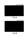
- FIGS. 6A and 6B respectively show images of PDMS microchannels coated with a metal oxide where formation of water droplets in toluene and toluene droplets in water, respectively, can be obtained in accordance with certain embodiments of the present invention.
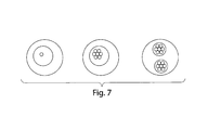
- FIG. 7 shows some exemplary double-emulsion and multiple-emulsion schematics that may be formed using the systems described herein in accordance with certain embodiments of the present invention.
- methods and systems for coating PDMS surfaces are provided.
- methods and systems for coating surfaces comprising hydroxyl groups e.g., functionalized PDMS surfaces, functionalized glass surfaces, etc.
- methods and systems for coating PDMS surfaces with metal oxides using a sol-gel chemistry are provided.
- methods and systems for coating PDMS surfaces with a non-porous layer of metal oxide are provided.
- Methods in accordance with certain embodiments include: (i) preparing a mixture comprising a sol-gel precursor to a metal oxide, a reaction catalyst, and a reaction inhibitor; (ii) reacting the mixture to form a preconverted sol-gel precursor, wherein the preconverted sol-gel precursor is of a form and/or molecular weight so that it does not diffuse into PDMS and is not in the form of a gel; (iii) forming a reactive PDMS surface; (iv) applying the preconverted sol-gel precursor onto the reactive PDMS surface; (v) binding the preconverted sol-gel precursor to the reactive PDMS surface; (vi) removing any unbound material; and (vii) converting the bound preconverted sol-gel precursor to a metal oxide to form a metal oxide coating on the PDMS surface.
- the metal oxide coating may be a non-porous coating that is resistant to organic molecules. In some other embodiments, the metal oxide coating may be readily treated to form reactive groups on the surface of the metal oxide.
- the invention is described herein primarily in the context of coatings on surfaces, coatings and methods that mitigate swelling of the underlying material, coating localized portions of surfaces, controlling hydrophobicity, etc. It is to be understood that any of the various aspects and options of the invention can be present, absent, and/or used alone or in combination with any other aspect, option, example, or embodiment.
- preconverted precursors or “preconverted sol-gel precursors” are meant to denote sol-gel precursors that have been reacted for a sufficient time so that they do not diffuse into the PDMS but may or may not have yet fully formed into a gel.
- reaction precursors or “reacted sol-gel precursors” are meant to denote sol-gel precursors that have been reacted to form a gel but may or may not have yet fully formed into a metal oxide.
- any portion of PDMS that forms an interface with another material will be referred to as a “PDMS surface.”
- the present application is generally applicable to any surfaces having hydroxyl groups thereon and is not limited solely to PDMS surfaces.
- the surface may comprise a metal oxide, glass, a polymer, etc.
- a microfluidic channel may be coated in a sol-gel material.
- “Microfluidic,” as used herein, refers to a device, apparatus, or system including at least one fluid channel having a cross-sectional dimension of less than about 1 millimeter (mm), and in some cases, a ratio of length to largest cross-sectional dimension of at least 3:1.
- a “channel,” as used herein, means a feature on or in an article (substrate) that at least partially directs flow of a fluid.
- the channel can have any cross-sectional shape (circular, oval, triangular, irregular, square or rectangular, or the like) and can be covered or uncovered. In embodiments where it is completely covered, at least one portion of the channel can have a cross-section that is completely enclosed, or the entire channel may be completely enclosed along its entire length with the exception of its inlet(s) and/or outlet(s).
- a channel may also have an aspect ratio (length to average cross sectional dimension) of at least 2:1, more typically at least 3:1, 5:1, 10:1, 15:1, 20:1, or more.
- An open channel generally will include characteristics that facilitate control over fluid transport, e.g., structural characteristics (an elongated indentation) and/or physical or chemical characteristics (hydrophobicity vs. hydrophilicity) or other characteristics that can exert a force (e.g., a containing force) on a fluid.
- the fluid within the channel may partially or completely fill the channel.
- the fluid may be held within the channel, for example, using surface tension (i.e., a concave or convex meniscus).
- the channel may be of any size, for example, having a largest dimension perpendicular to fluid flow of less than about 5 mm or 2 mm, or less than about 1 mm, or less than about 500 microns, less than about 200 microns, less than about 100 microns, less than about 60 microns, less than about 50 microns, less than about 40 microns, less than about 30 microns, less than about 25 microns, less than about 10 microns, less than about 3 microns, less than about 1 micron, less than about 300 nm, less than about 100 nm, less than about 30 nm, or less than about 10 nm.
- the dimensions of the channel may be chosen such that fluid is able to freely flow through the article or substrate.
- the dimensions of the channel may also be chosen, for example, to allow a certain volumetric or linear flowrate of fluid in the channel.
- the number of channels and the shape of the channels can be varied by any method known to those of ordinary skill in the art. In some cases, more than one channel or capillary may be used. For example, two or more channels may be used, where they are positioned inside each other, positioned adjacent to each other, positioned to intersect with each other, etc.
- Sol-gel precursors that may be utilized include, but are not limited to, molecules that contain on average two or more hydrolysable moieties that can form metal oxides upon hydrolysis. Some examples include alkoxides, acetates, alkanoates, nitrates, halides, and the like of metals or metalloids.
- Some suitable metals or metalloids include aluminum, antimony, barium, bismuth, cadmium, calcium, cerium, cesium, chromium, cobalt, copper, dysprosium, erbium, gadolinium, germanium, hafnium, holmium, indium, iridium, iron, lanthanum, lead, lithium, lutetium, magnesium, manganese, molybdenum, neodymium, nickel, niobium, palladium, potassium, praseodymium, rhodium, rubidium, ruthenium, samarium, scandium, silicon, silver, sodium, strontium, tantalum, terbium, thallium, tin, titanium, tungsten, vanadium, ytterbium, yttrium, zirconium, and the like.
- sol-gel precursors can include ethyoxysilane, methoxysilane, titanium isopropoxide, vanadium butoxide, hexafluorosilicic acid, methyltrichlorosilane, and the like.
- Other examples include silsesquioxanes, such as alkyltrialkoxysilanes.
- the sol-gel precursor can be or comprise tetraethyl orthosilicate (TEOS), methyltriethoxysilane (MTES), or mixtures thereof.
- TEOS tetraethyl orthosilicate
- MTES methyltriethoxysilane
- the sol-gel precursors Before applying the precursors to the PDMS surface, the sol-gel precursors can be further reacted to form preconverted precursors. Formation of the pre-converted sol-gel precursor has a number of benefits including, and not limited to, reducing diffusion of the sol-gel precursor into the PDMS, reducing swelling of the PDMS, and reducing distortion of the features that are present in or on the PDMS.
- a mixture containing the sol-gel precursor, reaction catalyst, reaction inhibitor, solvent, water, and/or the like can be formed and allowed to react.
- Some of the variables that can be controlled during the formation of the preconverted precursors include reactivity of the precursor (e.g., the type of precursor utilized), reaction temperature, reaction time, reaction catalysts, reaction inhibitors, relative concentration of the precursor, catalyst, inhibitors and/or solvent, and the like.
- preconverted precursors can include from about ⁇ 25° C. to about 100° C., such as 20-70° C., 20-60° C., 20-50° C., 20-40° C., and 20-30° C. In certain embodiments, preconverted precursors can be formed at about 100° C.
- Some suitable times to form preconverted precursors can range from about 1 second to about several weeks.
- a suitable range may be from about 1-10,000 seconds, 10-1,000 seconds, 50-500 seconds, and the like.
- preconverted precursors can be carried out at multiple temperatures and at multiple times.
- preconverted precursors can be formed by forming a miscible mixture of the reactants at elevated temperature, such as 100° C. for 10 seconds, and then at 65° C. for about 12 hours.
- pH of the mixture can be adjusted which can change the time and temperature of reaction.
- formation of preconverted precursors using lower pH (e.g., pH of about 0.5) mixtures can be carried out at lower temperatures and/or shorter times while formation of preconverted precursors using higher pH (e.g., pH of about 2 to 4) can be carried out at higher temperatures and/or longer times.
- pH of the mixture can be adjusted which can change the time and temperature of reaction.
- formation of preconverted precursors using lower pH (e.g., pH of about 0.5) mixtures can be carried out at lower temperatures and/or shorter times while formation of preconverted precursors using higher pH (e.g., pH of about 2 to 4) can be carried out at higher temperatures and/or longer times.
- the modification of such reaction conditions will be readily apparent to one of ordinary skill in the art.
- sol-gel precursor when molecules that contain on average two or more hydrolyzable moieties that can form metal oxides upon hydrolysis are utilized as the sol-gel precursor, a suitable amount water can be added to the mixture to form preconverted precursors.
- catalysts can be added to the mixture to speed up the rate of reaction of the precursors to form preconverted precursors.
- suitable catalysts include acids, such as acetic acid, hydrochloric acid, nitric acid, sulfuric acid, oxalic acid, phosphoric acid, and the like.
- reaction inhibitors can be added to the mixture to slow down the rate of reaction.
- Reaction inhibitors may be beneficial in slowing down the reaction kinetics to control the viscosity and delay the onset of gel formation.
- suitable inhibitors include alcohols, solvents that are miscible with water, or similar solvents. For example, methanol, ethanol, isopropanol, and the like can be utilized as suitable reaction inhibitors.
- sol-gel precursor:catalyst:inhibitor Some suitable range of relative molar concentrations of sol-gel precursor:catalyst:inhibitor range from about 5:1:1 to about 1:1:10. For example, 2:1:1 molar ratios of sol-gel precursor:catalyst:inhibitor can be utilized. Other variations, such as 1:1:1:1 molar ratios of a first sol-gel precursor:second sol-gel precursor:catalyst:inhibitor can be utilized.
- preconverted precursors can reduce diffusion of the precursors into the PDMS. Without wishing to be bound by theory, preconversion of the precursor may lead to at least one of two beneficial effects that reduce diffusion of the precursors into the PDMS.
- preconverted precursors can tend to decrease the entropy of mixing.
- preconverted precursors that have higher molecular weights than the monomeric form of precursors may lead to a lower tendency for the preconverted precursors to mix, and hence diffuse, into the PDMS bulk.
- the preconversion may lead to conversion of the precursors from a molecule having a hydrophobic character in the monomeric state to a molecule having a hydrophilic character in the preconverted precursor state.
- the conversion of the precursor from a hydrophobic character to a hydrophilic character may lead to an increase in the enthalpy of mixing.
- preconverted precursors with a hydrophilic character may lead to a lower desirability for the preconverted precursors to mix, and hence diffuse, into the hydrophobic PDMS.
- the preconverted precursors can be reacted so that less than about 50%, 40%, 40%, 20%, 10%, 5%, or 1% swelling of the PDMS occurs.
- the conversion to a preconverted sol-gel precursor can generally be carried out to a point before gel formation occurs, (or before the onset of the gel-point), which can be measured by a change of the reacting mixture from a viscous liquid to a solid gel where flow is significantly reduced.
- Gel formation can be also be viewed as the point at which the first network molecule is formed as reaction of the sol-gel precursors occur.
- the gel point can occur abruptly where a liquid rapidly (on the order of seconds and/or minutes) changes to a solid and does not flow.
- PDMS surfaces can be prepared in any number of suitable methods. For example, a flat, curved, grooved, pitched, and any other types of surfaces can be formed.
- one or more channels can be formed on a pre-existing PDMS surface or within the bulk of the PDMS, for example, by contacting a PDMS surface having one or more channels with a flat PDMS surface.
- Other suitable techniques for forming PDMS surfaces will be readily apparent to one of ordinary skill in the art.
- Size of the PDMS surface and/or channels formed thereon and/or therein is not limited. Size of the PDMS surface and/or channels can be several nanometers in dimension to several meters. In certain embodiments, microchannels having dimensions that are about 1-1000 microns can be formed on or in the PDMS. In some other embodiments, nanochannels having dimensions that are about 10 to 1000 nanometer can be formed on or in the PDMS.
- the size of the channels can be designed so that flow of material into each of the individual network channels can be achieved in equal or unequal amounts.
- size of the channels can be designed so that the pressure drop that occurs during flow into multiple channels from a central inlet are substantially equal to lead to substantially flow of fluids in each of the multiple channels.
- the PDMS surface can be treated to form reactive groups on the surface.
- the reactive groups can be reactive with or have a high affinity for the preconverted precursors to allow the preconverted precursor to form a link on the PDMS surface.
- a suitable link may be in the form of a covalent bond, an ionic bond, van der Waals interactions, charge interactions, and the like.
- the PDMS surface can be treated with a plasma, base, ultraviolet radiation, chemical oxidation, and the like.
- a plasma using oxygen or air can be utilized to form reactive silanol groups on the PDMS surface.
- Other suitable techniques for forming reactive groups on a PDMS surface will be readily apparent to one of ordinary skill in the art.
- PDMS surfaces can be selectively patterned or masked so that reactive groups are formed on only certain desired portions of the PDMS.
- a flat PDMS surface may be provided with a line grating so that only exposed portions of the PDMS form reactive groups thereon.
- a topologically flat PDMS surface may have patterned regions reactive and unreactive portions.
- the preconverted precursor can be applied to at least a portion of the reactive PDMS surface. Any suitable technique for applying the preconverted precursor to the reactive PDMS surface can be utilized, such as solution casting, spin casting, capillary flow, and the like.
- the preconverted precursor can be filtered prior to application onto the reactive PDMS surface to remove any undesired impurities, such as large particulate impurities.
- application of the preconverted precursors can be determined by the extent of reaction of the preconverted precursors.
- Conditions in which the preconverted precursors can flow through the channels without clogging may be determined by the viscosity of the preconverted precursors and the pressure that can be applied within the channels. Accordingly, the dimensions of the channels, viscosity of the preconverted precursors, and the speed of application may be adjusted as needed.
- a continuous flow of the preconverted precursors to the reactive PDMS surface may be beneficial.
- a continuous flow of the preconverted precursors to the reactive PDMS surface may be accomplished by using, for example, a hand syringe, a syringe pump, and the like.
- Suitable rate of flow can be determined based on various experimental parameters, such as the concentration of preconverted precursor in the solution, temperature, desired coating thickness, and the like.
- Some suitable flow rates include 5 to 5000 microliters per hour for 10 seconds to a few days, depending on the desired conditions. For example, 500 microliters per hour for about 30 minutes may be utilized.
- the relative size of the channels can be designed so that flow of material into the network channels can lead to equal or unequal distribution of the preconverted precursor in each channel.
- the equal of unequal distribution of the preconverted precursor in each channel can be effected by the flow rate of the preconverted precursor.
- the preconverted precursor may bind, such as through a covalent bond, an ionic bond, van der Waals interactions, charge interactions, and the like, to the reactive surface of the PDMS.
- Parameters such as time and/or temperature, may be changed to affect the rate of binding. For example, binding may be carried out in room temperature or at elevated temperatures.
- Binding of the preconverted precursor may be accompanied by the formation of reacted precursor, which may also bind to the reactive PDMS surface. Moreover, additional preconverted precursor and/or reacted precursor may successively bind onto the preconverted precursor and/or reacted precursors previously bound to the reactive PDMS surface. Accordingly, the thickness of the preconverted precursor and/or reactive precursor formed on the reactive PDMS surface may increase over time.
- any unbound material may be removed.
- Unbound material may include any material contained in the mixture, such as unbound preconverted precursor, reacted precursor, catalyst, inhibitor, solvent, and the like.
- any material that is immiscible with the gel or the precursor can be utilized to displace any unbound material.
- materials that wet the reactive PDMS less than the preconverted precursors can be utilized.
- hydrophobic liquids and gases such as noble gases, oxygen, hydrogen, carbon dioxide, mixtures thereof, and the like, can be utilized.
- one or more inert fluids such as an oil, solvent, silanes, and the like can be used to displace any unbound material.
- FC3283 oil, ethanol, HFE7100, and the like can be utilized as inert fluids.
- Such inert fluids may be provided as a mixture or in successive combination.
- oil and air may be utilized to displace the unbound material.
- flow of air may be followed by oil.
- gel formation throughout the entire channel can be avoided by carrying out the removal of unbound/undeposited material at a suitable time.
- removal of the unbound/undeposited material can be carried out after about 1, 2, 3, 5, 10, 20, 30, 100, 1000, 1000, 10,000 seconds (and the like) after binding of the preconverted precursor to the PDMS channel has started.
- removal of unbound material may be optional.
- removal of unbound material may not be needed.
- the preconverted precursor and/or reacted precursor can be allowed to form the desired metal oxide film, such as a silica coating.
- the coated PDMS surfaces can be allowed to react for additional time (e.g., overnight) for the reaction to go to completion to form a metal oxide coating. Additional parameters, such as temperature, pressure, and the like, can be altered to control the reaction.
- the metal oxide and/or sol-gel precursor coating can be of any desired thickness.
- the coating may have a thickness of no more than about 100 micrometers, no more than about 30 micrometers, no more than about 10 micrometers, no more than about 3 micrometers, or no more than about 1 micrometer.
- the coating may have a thickness of at least 0.1 micrometers, at least 1 micrometer, at least 10 micrometers, at least 30 micrometers, or at least 100 micrometers. Thicker coatings may be desirable in some cases, for instance, in applications in which higher chemical resistance is desired. However, thinner coatings may be desirable in other applications, for instance, within relatively small microfluidic channels.
- metal oxide coating after the formation of a metal oxide coating, further modification to the metal oxide coating can be carried out.
- the metal oxide coating can be rendered reactive and the above-described techniques for deposition metal oxide may be repeated as desired, as would be readily apparent to one of ordinary skill in the art.
- numerous techniques such as HCl treatment, mild HF treatment, hydrogen peroxide treatment, piranha treatment, silane based chemistry, polymer adsorption, polymer grafting, and the like will be readily apparent to one of ordinary skill in the art to form silanol groups on the silica surface.
- additional silica sol-gel precursors either in monomeric or preconverted precursor form, can be applied to form thicker coatings.
- Additional modifications can include deposition of other coatings that have desired properties, such as superhydrophilic and/or superhydrophobic properties.
- desired properties such as superhydrophilic and/or superhydrophobic properties.
- silica when silica is formed as the coating, reactive silanol groups can be formed on the silica surface. Desired materials, such as silica nanoparticles, can be applied to form superhydrophilic surfaces.
- materials such as perfulorosilanes, perfluorinated silanes, alkyl silanes (e.g., octadecyltrichlorosilanes), and the like can be applied to form superhydrophobic surfaces.
- the present invention provides a PDMS surface where a metal oxide coating is bound on the surface of the PDMS without any significant diffusion of the metal oxide precursors into the bulk of the PDMS.
- the present invention provides a microfluidic device having one or more channels, where metal oxide coating is bound on the channel walls of the microfluidic device.
- the metal oxide coating is covalently bound to the PDMS surface or the channel walls of the microfluidic device.
- the present invention can be utilized in a wide range of applications.
- formation of a metal oxide coating on PDMS surface can provide the ability to use organic solvents, ability to control adsorption of certain compounds, ability to control wetting and flow behavior in microfluidic channels, and the like.
- Some exemplary applications involving microfluidics using organics solvents include chemical synthesis in confined dimensions, screening of organic chemical reactions that occur in one-phase Poiseuille flow and/or in heterophase flow (e.g., flows containing bubbles and/or droplets), and the like.
- polymers or other molecules can be grafted onto the coated PDMS surfaces.
- biological molecules such as amino acids and/or proteins can be grafted onto the surface in a spatially defined pattern to carry out numerous sensing applications.
- the porosity of the coatings can be controlled during the formation of the coatings. Without wishing to be bound by theory, it is generally thought that lower pH mixtures can lead to formation of more porous coatings. Hence, coatings made from mixtures having higher pH values can lead to increased interfacial surface area where functional groups are present. In other words, the density per unit channel length of functional groups that are available on the coating surface can increase. This means that if used as a sensor by grafting on desired molecules, the sensitivity of the sensors can be tuned.
- certain embodiments can provide cylindrical channels although the coating is deposited on a square PDMS channel.
- Such cylindrical channels may have additional advantages of simplifying flow profiles, which can in turn facilitate modeling, lead to more accurate prediction of flow properties, and reduced complicated hydrodynamic effects from interfering with flow.
- monodisperse emulsions such as shown in FIGS. 6A and 6B (albeit with different materials) can be obtained, which in turn can be utilized to make monodisperse particles.
- the coatings can be functionalized in a spatially defined manner to improve or decrease wettability in desired places, which in turn can allow the formation of double-emulsions or multiple emulsions with organic solvents, as shown in FIG. 7 .
- Such structures may allow the formation of biologically relevant structures, such as lipid vesicles and membranes.
- the hydrophobicity of the coating can be controlled, for instance, such that a first portion of the coating is relatively hydrophobic, and a second portion of the coating is more or less relatively hydrophobic than the first portion.
- the hydrophobicity of the coating can be determined using techniques known to those of ordinary skill in the art, for example, using contact angle measurements such as those discussed below.
- a first portion of a substrate may have a hydrophobicity that favors an organic solvent to water, while a second portion may have a hydrophobicity that favors water to the organic solvent.
- Some other exemplary applications include controlling the adsorption properties of certain compounds.
- Still other exemplary applications include controlling the wetting and flow behavior of fluids in microfluidic channels.
- capillary electrophoresis can be carried out with the systems described herein.
- Tetraethyl orthosilicate was utilized as a suitable sol-gel precursor.
- Preconverted precursors was formed by mixing the TEOS with an acid catalyst and a reaction inhibitor.
- the acid catalyst was dilute hydrochloric acid (HCl), which was obtained by forming a 1:1000 mixture by volume of 38% HCl with water to obtain a pH of about 2.
- the reaction inhibitor was ethanol (EtOH).
- a 2:1:1 ratio (by volume) of TEOS:HCl:EtOH was mixed and allowed to react at room temperature for about 24 hours to form the preconverted precursors. At room temperature, onset of gel formation appears to occur approximately about 7 days after the mixture was first mixed.
- Channels having at least 15 ⁇ m height and width was formed by soft lithography.
- the channels were all connected to a central fluid inlet port and a central fluid output port where fluids can be injected into and out of the channels, respectively.
- the exposed PDMS surfaces including the walls of the PDMS channels, were rendered reactive by oxygen plasma treatment for about 5 minutes.
- a flat slab of PDMS was also rendered reactive by oxygen plasma treatment for about 5 minutes.
- the two PDMS pieces were joined together at the reactive surfaces to form channels having a rectangular cross-section (at least 15 ⁇ 15 ⁇ m), where the four channel walls have reactive PDMS surfaces.
- a syringe was connected with a tube that can fit the central inlet port of the PDMS (e.g., a polyethylene tube having 1.09 mm outer diameter).
- the syringe was first filled with an inert fluid, such as fluorocarbon oil FC 3283 (e.g., more than 20 p. 1), then with an air bubble (e.g., about 1 ⁇ l), followed by the preconverted precursor mixture (e.g., about 20 ⁇ l).
- FC 3283 e.g., more than 20 p. 1
- the tube was connected to the inlet port of the PDMS and the syringe was pumped using a syringe pump at 400 ⁇ l/h so that the preconverted precursor first flows into the channels, followed by the air bubble, and finally followed by the fluorocarbon oil.
- the channels were filled with oil and was allowed to react for about 30 minutes whereupon the remaining fluorocarbon oil was removed using air. Additional reaction time, before or after removal of the oil, may be provided.
- the resulting structure is a silica coating on the PDMS channel walls.
- a 3:2:1 ratio (by volume) of TEOS:HCl:EtOH was mixed and allowed to react at room temperature for about 24 hours to form the preconverted precursors.
- Channels about 50 ⁇ m in height and width, were formed by soft lithography.
- the channels were connected to a central fluid inlet port and a central fluid output port.
- the exposed PDMS surfaces including the walls of the PDMS channels, were oxygen plasma treatment for about 5 minutes and bonded to a glass slide to form channels having a rectangular cross-section (at least 50 ⁇ 50 ⁇ m), where three channel walls have reactive PDMS surfaces.
- a syringe was connected with a tube that can fit the central inlet port of the PDMS.
- the preconverted precursor mixture was filtered with a glass filter and loaded into the syringe.
- the tube was then connected to the inlet port of the PDMS and syringe was pumped using a syringe pump at about 500 ⁇ l/h for 10 minutes. Then the channels were cleared by using air.
- the resulting structure is a silica coating on the PDMS channel that is impermeable to organic molecules.
- the channels were filled with a 50 ⁇ M Rhodamine B water solution.
- the same Rhodamine B solution was also filled in an uncoated PDMS channel. Both channels were allowed to dry out at room temperature for about 4 days.
- FIGS. 1A and 1B show confocal microscope images of the silica coated PDMS channel ( FIG. 1A ) and an uncoated PDMS channel ( FIG. 1B ).
- the bright (i.e., fluorescing) portions correspond to the areas where the Rhodamine B is present.
- FIG. 1A shows no noticeable diffusion of the Rhodamine B into the PDMS bulk while FIG. 1B shows almost a complete diffusion of the Rhodamine B into the PDMS bulk.
- FIGS. 2A-2C show several different 3D views of Rhodamine B dried on the silica coating walls (bottom of the channel corresponding to the glass slide was not imaged).
- the 3D views were obtained by reconstructing various different confocal microscope images, as would be readily apparent to one of ordinary skill in the art. As shown, silica is uniformly coated throughout the three PDMS channel walls.
- toluene was flowed through a PDMS channel coated with silica as described in Example 1 and a PDMS channel without any coating.
- FIG. 3A shows an image of the PDMS channel coated with silica immediately after toluene was passed through.
- FIG. 3B shows an image of the PDMS channel coated with silica about 0.6 seconds after toluene was passed through.
- FIG. 3C shows an image of the PDMS channel coated with silica about 13 seconds after toluene was passed through.
- FIG. 4A shows an image of the PDMS channel without any coating immediately after toluene was passed through.
- FIG. 4B shows an image of the PDMS channel without any coating about 0.6 seconds after toluene was passed through.
- FIG. 4C shows an image of the PDMS channel without any coating about 13 seconds after toluene was passed through.
- FIGS. 3A through 3C there is no appreciable change in the channel.
- the PDMS channel is shown to begin swelling immediately after toluene passes through the channel and swells considerably after about 13 seconds.
- TEOS tetraethyl orthosilicate
- MTES methyltriethoxysilane
- the sol-gel precursor mixture was placed in a glass vial and ethanol and water (at pH of about 2.5 to about 4.5 using HCl) was added.
- the ethanol (EtOH) served as a reaction inhibitor.
- the molar ratio of TEOS:MTES:water:EtOH was about 1:1:1:1.
- the mixture was initially phase separated.
- the glass vial containing the mixture was placed in a microwave and irradiated for 3 seconds. Approximately 10-20 irradiation pulses formed miscible liquids. Thereafter, the mixed liquids were allowed to react at about 65° C. overnight to form the preconverted precursors. At room temperature, onset of gel formation appears to occur approximately about 7 to 10 days later.
- Channels having at least 40 ⁇ m height and 50 ⁇ m width was formed by soft lithography (see FIG. 5A ).
- the channels were all connected to a central fluid inlet port and a central fluid output port where fluids can be injected into and out of the channels, respectively.
- the exposed PDMS surfaces, including the walls of the PDMS channels, were rendered reactive by oxygen plasma treatment for about 5 minutes.
- a flat slab of PDMS was also rendered reactive by oxygen plasma treatment for about 5 minutes.
- the two PDMS pieces were joined together at the reactive surfaces to form channels having a rectangular cross-section (at least 40 ⁇ 50 ⁇ m), where the four channel walls have reactive PDMS surfaces.
- a syringe was connected with a tube that can fit the central inlet port of the PDMS (e.g., a polyethylene tube having 1.09 mm outer diameter).
- the syringe was filled with the preconverted precursor mixture (e.g., about 1 ml).
- the PDMS channel was filled with the preconverted precursor mixture by hand. Thereafter, the PDMS channel filled with the preconverted precursor mixture was placed on a 100° C. hotplate for about 10 seconds. Then, 10 mL of air was blown into the channel while still on the hotplate by applying a firm steady pressure while the coating solidifies.
- the resulting structure is a silica coating on the PDMS channel walls as shown in FIG. 5B .
- thicker silica coatings which can be adjusted as desired.
- Such thicker silica coatings may promote further resistance to organic solvents that aggressively swell PDMS.
- PDMS microchannels were coated with silica as described above in Example 4. Subsequently, the silica coated channels were rendered hydrophobic by applying it with AQUAPEL. Thereafter, as shown in FIG. 6A , a mixture of toluene and water was flowed into the channel to obtain water droplets in toluene (water-in-toluene emulsion).
- the silica coated channels were rendered hydrophilic by treating with N-[3-trimethoxysilyl]propyl]ethylene diamine. As shown in FIG. 6B , a mixture of toluene and water was flowed into the channel toluene droplets in water (toluene-in-water emulsion).
- binding of the preconverted precursor to the PDMS surface allows the formation of metal oxide coatings that are also bound on the PDMS surface.
- Such strong binding of the metal oxide on the PDMS surface minimizes removal or dewetting of the metal oxide from the PDMS surface during use.
- the metal oxide coating can be further treated to form reactive metal oxide surfaces.
- a silicon oxide coating can natively have and/or can be further treated to form reactive silanol groups, much like the plasma treatment of PDMS can form reactive silanol groups on its surface. Accordingly, a wider range of silanols may be used for the post functionalization of the coated channels, as certain silanols that swells the PDMS, but not the coated channels, can now be utilized.
- the present invention can form reactive surfaces that are stable over longer periods of time.
- any material that becomes reacted with the reactive metal oxide surface is further anchored to the PDMS through the bound metal oxide coating. Accordingly, the present invention provide binding materials of interest to the metal oxide surface providing a durable coating of the material of interest.
- the present invention overcomes the problem of diffusion of the precursors into the PDMS, which cause swelling of the PDMS.
- the present invention provides a method for forming a metal oxide coating without significant deformation of the PDMS.
- chemicals that would have otherwise diffused into the PDMS can now be fully confined within the channel, minimizing any potential loss of materials during transport through the channels.
- PDMS can facilitate the fabrication many identical copies of a device into a tiny space on a single chip.
- Such a technique can increase the production rate by many orders of magnitude by making it massively parallel. For example, if particles formation from droplet is desired, numerous channels can be made to scale up the fabrication of multiple droplets in a single device.
- the present invention provide versatile and easy to fabrication metal oxide coatings on any type of surfaces of PDMS.
- machining or wet etching channels of glass is not only expensive and time consuming, but also has certain limitations in the sizes that can be made due to machining limitations.
- the present invention is applicable in a wide range of sizes with more or less the same versatility and ease of fabrication.
- the present invention is directed to each individual feature, system, article, material, kit, and/or method described herein.
- any combination of two or more such features, systems, articles, materials, kits, and/or methods, if such features, systems, articles, materials, kits, and/or methods are not mutually inconsistent, is included within the scope of the present invention.
- a reference to “A and/or B”, when used in conjunction with open-ended language such as “comprising” can refer, in one embodiment, to A only (optionally including elements other than B); in another embodiment, to B only (optionally including elements other than A); in yet another embodiment, to both A and B (optionally including other elements); etc.
- the phrase “at least one,” in reference to a list of one or more elements, should be understood to mean at least one element selected from any one or more of the elements in the list of elements, but not necessarily including at least one of each and every element specifically listed within the list of elements and not excluding any combinations of elements in the list of elements.
- This definition also allows that elements may optionally be present other than the elements specifically identified within the list of elements to which the phrase “at least one” refers, whether related or unrelated to those elements specifically identified.
- “at least one of A and B” can refer, in one embodiment, to at least one, optionally including more than one, A, with no B present (and optionally including elements other than B); in another embodiment, to at least one, optionally including more than one, B, with no A present (and optionally including elements other than A); in yet another embodiment, to at least one, optionally including more than one, A, and at least one, optionally including more than one, B (and optionally including other elements); etc.
Landscapes
- Chemical & Material Sciences (AREA)
- Engineering & Computer Science (AREA)
- Organic Chemistry (AREA)
- Materials Engineering (AREA)
- General Chemical & Material Sciences (AREA)
- Chemical Kinetics & Catalysis (AREA)
- Mechanical Engineering (AREA)
- Thermal Sciences (AREA)
- Physics & Mathematics (AREA)
- Metallurgy (AREA)
- Inorganic Chemistry (AREA)
- Ceramic Engineering (AREA)
- Life Sciences & Earth Sciences (AREA)
- Geochemistry & Mineralogy (AREA)
- Dispersion Chemistry (AREA)
- Physical Or Chemical Processes And Apparatus (AREA)
- Oxygen, Ozone, And Oxides In General (AREA)
Priority Applications (1)
| Application Number | Priority Date | Filing Date | Title |
|---|---|---|---|
| US12/733,086 US8883291B2 (en) | 2007-08-07 | 2008-08-07 | Metal oxide coating on surfaces |
Applications Claiming Priority (3)
| Application Number | Priority Date | Filing Date | Title |
|---|---|---|---|
| US96370907P | 2007-08-07 | 2007-08-07 | |
| PCT/US2008/009477 WO2009020633A2 (en) | 2007-08-07 | 2008-08-07 | Metal oxide coating on surfaces |
| US12/733,086 US8883291B2 (en) | 2007-08-07 | 2008-08-07 | Metal oxide coating on surfaces |
Publications (2)
| Publication Number | Publication Date |
|---|---|
| US20100239824A1 US20100239824A1 (en) | 2010-09-23 |
| US8883291B2 true US8883291B2 (en) | 2014-11-11 |
Family
ID=40113426
Family Applications (1)
| Application Number | Title | Priority Date | Filing Date |
|---|---|---|---|
| US12/733,086 Expired - Fee Related US8883291B2 (en) | 2007-08-07 | 2008-08-07 | Metal oxide coating on surfaces |
Country Status (3)
| Country | Link |
|---|---|
| US (1) | US8883291B2 (de) |
| EP (1) | EP2183408A2 (de) |
| WO (1) | WO2009020633A2 (de) |
Families Citing this family (31)
| Publication number | Priority date | Publication date | Assignee | Title |
|---|---|---|---|---|
| US9039273B2 (en) | 2005-03-04 | 2015-05-26 | President And Fellows Of Harvard College | Method and apparatus for forming multiple emulsions |
| US8741158B2 (en) | 2010-10-08 | 2014-06-03 | Ut-Battelle, Llc | Superhydrophobic transparent glass (STG) thin film articles |
| WO2009020663A1 (en) | 2007-08-09 | 2009-02-12 | Justin Lawyer | Foot spa tub pump and method |
| US8607374B2 (en) | 2007-08-09 | 2013-12-17 | Ecotech Marine, Llc | Foot spa tub pump and method |
| EP2271581A4 (de) * | 2008-03-28 | 2014-09-03 | Harvard College | Mikrofluidkanäle enthaltende flächen mit gesteuerten benetzungseigenschaften |
| WO2011028764A2 (en) | 2009-09-02 | 2011-03-10 | President And Fellows Of Harvard College | Multiple emulsions created using jetting and other techniques |
| KR100970462B1 (ko) * | 2010-02-09 | 2010-07-16 | 엘베스트지에이티 주식회사 | 에너지 절감형 방식용 금속도막 조성물 및 그 제조방법 |
| CA2733337C (en) | 2010-03-01 | 2018-12-11 | Timothy Marks | Fluid pump assembly |
| US8486534B2 (en) * | 2010-06-08 | 2013-07-16 | Bar-Ilan University | Surface-modified polymer films |
| US11292919B2 (en) | 2010-10-08 | 2022-04-05 | Ut-Battelle, Llc | Anti-fingerprint coatings |
| WO2012087350A2 (en) | 2010-12-21 | 2012-06-28 | President And Fellows Of Harvard College | Spray drying techniques |
| WO2012109138A1 (en) | 2011-02-07 | 2012-08-16 | President And Fellows Of Harvard College | Systems and methods for splitting droplets |
| JP6122843B2 (ja) | 2011-05-23 | 2017-04-26 | プレジデント アンド フェローズ オブ ハーバード カレッジ | 多重エマルジョンを含むエマルジョンの制御 |
| US8778848B2 (en) | 2011-06-09 | 2014-07-15 | Illumina, Inc. | Patterned flow-cells useful for nucleic acid analysis |
| US20140220350A1 (en) | 2011-07-06 | 2014-08-07 | President And Fellows Of Harvard College | Multiple emulsions and techniques for the formation of multiple emulsions |
| US10266702B2 (en) | 2012-06-08 | 2019-04-23 | University Of Houston System | Self-cleaning coatings and methods for making same |
| US9771656B2 (en) | 2012-08-28 | 2017-09-26 | Ut-Battelle, Llc | Superhydrophobic films and methods for making superhydrophobic films |
| US20140284001A1 (en) | 2012-09-21 | 2014-09-25 | President And Fellows Of Harvard College | Systems and methods for spray drying in microfluidic and other systems |
| PL2954114T3 (pl) * | 2013-02-06 | 2019-08-30 | Koninklijke Philips N.V. | Płyta do obróbki dla urządzenia do obróbki odzieży |
| CN105050718B (zh) | 2013-03-06 | 2018-04-24 | 哈佛学院院长及董事 | 形成相对单分散液滴的装置和方法 |
| US9694388B2 (en) | 2013-05-14 | 2017-07-04 | University Of Houston System | Waterproof coating with nanoscopic/microscopic features and methods of making same |
| US11141730B2 (en) | 2013-06-14 | 2021-10-12 | President And Fellows Of Harvard College | Coalescence of droplets |
| US20150239773A1 (en) | 2014-02-21 | 2015-08-27 | Ut-Battelle, Llc | Transparent omniphobic thin film articles |
| WO2017165791A1 (en) | 2016-03-25 | 2017-09-28 | President And Fellows Of Harvard College | Microfluidic determination of immune and other cells |
| CN109311010B (zh) | 2016-04-15 | 2022-05-17 | 哈佛学院院长及董事 | 用于收集液滴或其他实体的系统和方法 |
| JP2020522451A (ja) * | 2017-06-02 | 2020-07-30 | ワーナー バブコック インスティチュート フォア グリーン ケミストリー リミテッド ライアビリティー カンパニー | 金属酸化物フィルム、パターン化した金属酸化物表面、および揮発性有機化合物の濾過作用を生成する方法 |
| JP7165308B2 (ja) * | 2018-06-12 | 2022-11-04 | 日産自動車株式会社 | 撥水部材の製造方法、撥水部材及び該撥水部材を備える自動車部品 |
| KR102334956B1 (ko) * | 2018-11-01 | 2021-12-02 | 주식회사 엘지화학 | 차량용 램프 및 이의 제조 방법 |
| CN110579182A (zh) * | 2019-09-18 | 2019-12-17 | 吉林大学 | 一种基于pdms-罗丹明辅助的纳米通道形貌表征方法 |
| WO2024102720A2 (en) | 2022-11-07 | 2024-05-16 | Shennon Biotechnologies Inc. | Microfluidic devices for high throughput screening of cell-cell interactions |
| CN115971011B (zh) * | 2022-11-28 | 2023-12-08 | 中国科学院合肥物质科学研究院 | 一种高熵复合氧化物阻氢涂层及其制备方法 |
Citations (39)
| Publication number | Priority date | Publication date | Assignee | Title |
|---|---|---|---|---|
| US5512131A (en) | 1993-10-04 | 1996-04-30 | President And Fellows Of Harvard College | Formation of microstamped patterns on surfaces and derivative articles |
| WO1996029629A2 (en) | 1995-03-01 | 1996-09-26 | President And Fellows Of Harvard College | Microcontact printing on surfaces and derivative articles |
| US5948484A (en) | 1995-06-22 | 1999-09-07 | Gudimenko; Yuri | Modification of subsurface region of polymers and carbon-based materials |
| WO2001089787A2 (en) | 2000-05-25 | 2001-11-29 | President And Fellows Of Harvard College | Microfluidic systems including three-dimensionally arrayed channel networks |
| EP1164207A2 (de) | 2000-05-31 | 2001-12-19 | Japan Carlit Co., Ltd. | Verfahren zur Herstellung einer Metalloxydschicht |
| US6355198B1 (en) | 1996-03-15 | 2002-03-12 | President And Fellows Of Harvard College | Method of forming articles including waveguides via capillary micromolding and microtransfer molding |
| US6426371B1 (en) | 1999-04-02 | 2002-07-30 | Industrial Technology Research Institute | Sol materials |
| JP2003136500A (ja) | 2001-11-02 | 2003-05-14 | Kawamura Inst Of Chem Res | 樹脂ダイヤフラムを有するマイクロ流体デバイスの製造方法 |
| US20030104466A1 (en) * | 1997-04-04 | 2003-06-05 | Caliper Technologies Corporation | Microfluidic sequencing systems |
| US6576478B1 (en) * | 1998-07-14 | 2003-06-10 | Zyomyx, Inc. | Microdevices for high-throughput screening of biomolecules |
| JP2003230829A (ja) | 2001-12-06 | 2003-08-19 | Hitachi Ltd | 平面マイクロファクトリー |
| WO2003072831A1 (en) | 2002-02-27 | 2003-09-04 | Third Wave Technologies, Inc. | Surface modification, linker attachment, and polymerization methods |
| WO2003104774A1 (en) * | 2002-06-11 | 2003-12-18 | University Of Virginia Patent Foundation | Apparatus and method for the purification of nucleic acids |
| US20040028566A1 (en) | 2002-08-08 | 2004-02-12 | Ko Jong Soo | Microfluidic device for the controlled movement of fluid |
| JP2004125475A (ja) | 2002-09-30 | 2004-04-22 | Nippon Sheet Glass Co Ltd | 液体制御機構、該液体制御機構を備えた光スイッチバイオセンサ及び光スイッチポンプ部品 |
| WO2004081536A2 (en) * | 2003-03-12 | 2004-09-23 | Arizona Board Of Regents | Radical activated cleavage of biologics and microfluidic devices using the same |
| WO2005001121A1 (en) | 2003-06-30 | 2005-01-06 | Raustech Pty Ltd | Substrates for spatially selective micron and nanometer scale deposition and combinatorial modification and fabrication |
| JP2005103423A (ja) | 2003-09-30 | 2005-04-21 | Fuji Kagaku Kk | マイクロ化学デバイス |
| US20050127002A1 (en) | 2003-12-12 | 2005-06-16 | Zare Richard N. | Immobilized-enzyme microreactor devices for characterization of biomolecular analytes and associated methods |
| US20050172476A1 (en) | 2002-06-28 | 2005-08-11 | President And Fellows Of Havard College | Method and apparatus for fluid dispersion |
| US20050233899A1 (en) | 2001-12-21 | 2005-10-20 | Toshiaki Anzaki | Member having photocatalytic function and method for manufacture thereof |
| JP2005331286A (ja) | 2004-05-18 | 2005-12-02 | Nippon Kayaku Co Ltd | マイクロ化学デバイス |
| WO2006027757A2 (en) | 2004-09-09 | 2006-03-16 | Institut Curie | Microfluidic device using a collinear electric field |
| US20060088666A1 (en) | 2004-06-04 | 2006-04-27 | Applied Microstructures, Inc. | Controlled vapor deposition of biocompatible coatings over surface-treated substrates |
| KR20060049351A (ko) | 2004-10-25 | 2006-05-18 | 주식회사 에코솔루션 | 표면개질된 실리카 나노입자와 피디엠에스를 이용하여제조된 휘발성유기화합물 분리용 혼합 막, 이의 제조방법및 용도 |
| US20060163385A1 (en) | 2003-04-10 | 2006-07-27 | Link Darren R | Formation and control of fluidic species |
| US20060166537A1 (en) | 2005-01-27 | 2006-07-27 | Thompson John O | Method of making a patterned metal oxide film |
| US20060171990A1 (en) | 2005-02-03 | 2006-08-03 | Soheil Asgari | Drug delivery materials made by sol/gel technology |
| WO2006086841A1 (en) | 2005-02-15 | 2006-08-24 | Rpo Pty Limited | Photolithographic patterning of polymeric materials |
| WO2006096571A2 (en) | 2005-03-04 | 2006-09-14 | President And Fellows Of Harvard College | Method and apparatus for forming multiple emulsions |
| US20070005024A1 (en) | 2005-06-10 | 2007-01-04 | Jan Weber | Medical devices having superhydrophobic surfaces, superhydrophilic surfaces, or both |
| US20070000342A1 (en) | 2005-06-16 | 2007-01-04 | Keisuke Kazuno | Ball screw |
| US20070054119A1 (en) | 2005-03-04 | 2007-03-08 | Piotr Garstecki | Systems and methods of forming particles |
| US20070224082A1 (en) | 2005-07-26 | 2007-09-27 | Kazufumi Ogawa | Biochemical chip and production method thereof |
| US7431889B2 (en) * | 2003-01-30 | 2008-10-07 | Gyros Patent Ab | Inner walls of microfluidic devices |
| WO2008121342A2 (en) | 2007-03-28 | 2008-10-09 | President And Fellows Of Harvard College | Emulsions and techniques for formation |
| JP2008284626A (ja) | 2007-05-16 | 2008-11-27 | Miraial Kk | マイクロ流路デバイス |
| WO2009120254A1 (en) | 2008-03-28 | 2009-10-01 | President And Fellows Of Harvard College | Surfaces, including microfluidic channels, with controlled wetting properties |
| US8084085B2 (en) * | 2003-12-24 | 2011-12-27 | Corning Incorporated | Coated microstructures and methods of coating same |
-
2008
- 2008-08-07 EP EP08795101A patent/EP2183408A2/de not_active Withdrawn
- 2008-08-07 US US12/733,086 patent/US8883291B2/en not_active Expired - Fee Related
- 2008-08-07 WO PCT/US2008/009477 patent/WO2009020633A2/en not_active Ceased
Patent Citations (45)
| Publication number | Priority date | Publication date | Assignee | Title |
|---|---|---|---|---|
| US5512131A (en) | 1993-10-04 | 1996-04-30 | President And Fellows Of Harvard College | Formation of microstamped patterns on surfaces and derivative articles |
| WO1996029629A2 (en) | 1995-03-01 | 1996-09-26 | President And Fellows Of Harvard College | Microcontact printing on surfaces and derivative articles |
| US5948484A (en) | 1995-06-22 | 1999-09-07 | Gudimenko; Yuri | Modification of subsurface region of polymers and carbon-based materials |
| US6355198B1 (en) | 1996-03-15 | 2002-03-12 | President And Fellows Of Harvard College | Method of forming articles including waveguides via capillary micromolding and microtransfer molding |
| US20030104466A1 (en) * | 1997-04-04 | 2003-06-05 | Caliper Technologies Corporation | Microfluidic sequencing systems |
| US6576478B1 (en) * | 1998-07-14 | 2003-06-10 | Zyomyx, Inc. | Microdevices for high-throughput screening of biomolecules |
| US6426371B1 (en) | 1999-04-02 | 2002-07-30 | Industrial Technology Research Institute | Sol materials |
| WO2001089787A2 (en) | 2000-05-25 | 2001-11-29 | President And Fellows Of Harvard College | Microfluidic systems including three-dimensionally arrayed channel networks |
| EP1164207A2 (de) | 2000-05-31 | 2001-12-19 | Japan Carlit Co., Ltd. | Verfahren zur Herstellung einer Metalloxydschicht |
| JP2003136500A (ja) | 2001-11-02 | 2003-05-14 | Kawamura Inst Of Chem Res | 樹脂ダイヤフラムを有するマイクロ流体デバイスの製造方法 |
| JP2003230829A (ja) | 2001-12-06 | 2003-08-19 | Hitachi Ltd | 平面マイクロファクトリー |
| US20050233899A1 (en) | 2001-12-21 | 2005-10-20 | Toshiaki Anzaki | Member having photocatalytic function and method for manufacture thereof |
| JP2005519264A (ja) | 2002-02-27 | 2005-06-30 | サード・ウェーブ・テクノロジーズ・インク | 表面修飾、リンカー結合、および重合方法 |
| WO2003072831A1 (en) | 2002-02-27 | 2003-09-04 | Third Wave Technologies, Inc. | Surface modification, linker attachment, and polymerization methods |
| WO2003104774A1 (en) * | 2002-06-11 | 2003-12-18 | University Of Virginia Patent Foundation | Apparatus and method for the purification of nucleic acids |
| US20050172476A1 (en) | 2002-06-28 | 2005-08-11 | President And Fellows Of Havard College | Method and apparatus for fluid dispersion |
| US20040028566A1 (en) | 2002-08-08 | 2004-02-12 | Ko Jong Soo | Microfluidic device for the controlled movement of fluid |
| JP2004125475A (ja) | 2002-09-30 | 2004-04-22 | Nippon Sheet Glass Co Ltd | 液体制御機構、該液体制御機構を備えた光スイッチバイオセンサ及び光スイッチポンプ部品 |
| US7431889B2 (en) * | 2003-01-30 | 2008-10-07 | Gyros Patent Ab | Inner walls of microfluidic devices |
| WO2004081536A2 (en) * | 2003-03-12 | 2004-09-23 | Arizona Board Of Regents | Radical activated cleavage of biologics and microfluidic devices using the same |
| US20060163385A1 (en) | 2003-04-10 | 2006-07-27 | Link Darren R | Formation and control of fluidic species |
| WO2005001121A1 (en) | 2003-06-30 | 2005-01-06 | Raustech Pty Ltd | Substrates for spatially selective micron and nanometer scale deposition and combinatorial modification and fabrication |
| JP2007538226A (ja) | 2003-06-30 | 2007-12-27 | ロウステック プロプライエタリー リミテッド | 空間的に選択的なマイクロ及びナノメートルスケールの付着用の基体及びコンビナトリアル修正及び成形加工 |
| JP2005103423A (ja) | 2003-09-30 | 2005-04-21 | Fuji Kagaku Kk | マイクロ化学デバイス |
| US20050127002A1 (en) | 2003-12-12 | 2005-06-16 | Zare Richard N. | Immobilized-enzyme microreactor devices for characterization of biomolecular analytes and associated methods |
| US8084085B2 (en) * | 2003-12-24 | 2011-12-27 | Corning Incorporated | Coated microstructures and methods of coating same |
| JP2005331286A (ja) | 2004-05-18 | 2005-12-02 | Nippon Kayaku Co Ltd | マイクロ化学デバイス |
| US20060088666A1 (en) | 2004-06-04 | 2006-04-27 | Applied Microstructures, Inc. | Controlled vapor deposition of biocompatible coatings over surface-treated substrates |
| WO2006027757A2 (en) | 2004-09-09 | 2006-03-16 | Institut Curie | Microfluidic device using a collinear electric field |
| KR20060049351A (ko) | 2004-10-25 | 2006-05-18 | 주식회사 에코솔루션 | 표면개질된 실리카 나노입자와 피디엠에스를 이용하여제조된 휘발성유기화합물 분리용 혼합 막, 이의 제조방법및 용도 |
| US20060166537A1 (en) | 2005-01-27 | 2006-07-27 | Thompson John O | Method of making a patterned metal oxide film |
| US20060171990A1 (en) | 2005-02-03 | 2006-08-03 | Soheil Asgari | Drug delivery materials made by sol/gel technology |
| JP2008530317A (ja) | 2005-02-15 | 2008-08-07 | アールピーオー プロプライエタリー リミテッド | ポリマー材料のフォトリソグラフィックパターニング |
| WO2006086841A1 (en) | 2005-02-15 | 2006-08-24 | Rpo Pty Limited | Photolithographic patterning of polymeric materials |
| WO2006096571A2 (en) | 2005-03-04 | 2006-09-14 | President And Fellows Of Harvard College | Method and apparatus for forming multiple emulsions |
| US20070054119A1 (en) | 2005-03-04 | 2007-03-08 | Piotr Garstecki | Systems and methods of forming particles |
| US20070005024A1 (en) | 2005-06-10 | 2007-01-04 | Jan Weber | Medical devices having superhydrophobic surfaces, superhydrophilic surfaces, or both |
| US20070000342A1 (en) | 2005-06-16 | 2007-01-04 | Keisuke Kazuno | Ball screw |
| US20070224082A1 (en) | 2005-07-26 | 2007-09-27 | Kazufumi Ogawa | Biochemical chip and production method thereof |
| WO2008121342A2 (en) | 2007-03-28 | 2008-10-09 | President And Fellows Of Harvard College | Emulsions and techniques for formation |
| US20090012187A1 (en) | 2007-03-28 | 2009-01-08 | President And Fellows Of Harvard College | Emulsions and Techniques for Formation |
| US7776927B2 (en) | 2007-03-28 | 2010-08-17 | President And Fellows Of Harvard College | Emulsions and techniques for formation |
| JP2008284626A (ja) | 2007-05-16 | 2008-11-27 | Miraial Kk | マイクロ流路デバイス |
| WO2009120254A1 (en) | 2008-03-28 | 2009-10-01 | President And Fellows Of Harvard College | Surfaces, including microfluidic channels, with controlled wetting properties |
| US20110123413A1 (en) | 2008-03-28 | 2011-05-26 | President And Fellows Of Harvard College | Surfaces, including microfluidic channels, with controlled wetting properties |
Non-Patent Citations (28)
| Title |
|---|
| Abate, A. et al., "Glass coating for PDMS microfluidic channels by sol-gel methods", Lab on a Chip, vol. 8, pp. 516-518 (2008). |
| Angell, J., et al., "Silicon Micromechanical Devices," Scientific American, vol. 248, pp. 44-55 (1983). |
| Arkles, B. et al. "Tailoring surfaces with silanes" Chemtech Dec. 1977, 766-778. |
| Duffy, D., et al., "Rapid Prototyping of Microfluidic Systems in Poly(dimethylsiloxane)", Anal. Chem., vol. 70, pp. 4974-4984 (1998). |
| Fiorini, G. et al. "Fabrication of thermoset polyster microfluidic devices and embossing masters using rapid prototyped polydimethylsiloxane molds" Lab. Chip, 2003, 3, 158-163. |
| International Preliminary Report on Patentability for PCT/US2008/009477 mailed Feb. 18, 2010. |
| International Preliminary Report on Patentability for PCT/US2009/000850 mailed Oct. 7, 2010. |
| International Search Report and Written Opinion for PCT Application PCT/US2008/009477 dated Jun. 24, 2009. |
| International Search Report from PCT/US2009/000850, mailed May 29, 2009. |
| Japanese Office Action for Application No. JP 2011-501785 mailed Jun. 25, 2013. |
| Japanese Office Action for Application No. JP 2011-501785 mailed Mar. 26, 2014. |
| Kelly, R. et al. "Thermal Bonding of Polymeric Capillary Electrophoresis Microdevices in Water" Anal. Chem. 2003, 75, 1941-1945. |
| Lee et al., Synthetic control of molecular weight and microstructure of processible poly(methylsilsesquioxane)s for low-dielectric thin film applications. Polymer. Oct. 2001;42(21):9085-89. |
| Lee, D. et al. "All-Nanoparticle Thin-Film Coatings" Nano Letters 2006, vol. 6, No. 10, 2305-2312. |
| Li, et al., "The Impact of Ultraviolet Light on Bacterial Adhesion to Glass and Metal Oxide-Coated Surface." Colloids and Surfaces B: Biointerfaces, 41, pp. 153-161 (2005). |
| Notice of Allowance for U.S. Appl. No. 12/935,203 mailed Apr. 23, 2014. |
| Notice of Allowance for U.S. Appl. No. 12/935,203 mailed Mar. 26, 2014. |
| Office Action for U.S. Appl. No. 12/935,203 mailed Mar. 4, 2013. |
| Office Action for U.S. Appl. No. 12/935,203 mailed Sep. 13, 2013. |
| Parashar, V. et al. "The Sol-Gel Process for Realisation of Optical Micro-Structures in Glass" Key Engineering Materials vols. 264-268 (2004), pp. 371-374. |
| Roman, G. et al. "Sol-Gel Modified Poly0Dimethylsiloxane) Microfluidic Devices with High Electroosmotic Mobilities and Hydrophilic Channel Wall Characteristics" Anal. Chem. 2005, 77, 1414-1422. |
| Roman, G. et al. "Surface Engineering of Poly(dimethylsiloxane) Microfluidic Devices Using Transition Metal Sol-Gel Chemistry" Langmuir 2006, 22, 4445-4451. |
| Sakai, Y. et al. "Silica coating on plastics by liquid phase deposition (LPD) method" Thin Solid Films 392 (2001) 294-298. |
| Soppera, et al. "Optimization of Radical Photopolymerization in Hybrid Sol-Gel Glasses: Advantages of Biocomponent Photoactive Systems," Mat Res Soc Symp Proc., vol. 726. (2002). |
| Vickers, J. et al. "Generation of Hydrophilic Poly(dimethylsiloxane) for High-Performance Microchip Electrophoresis" Anal. Chem. 2006, 78, 7446-7452. |
| Wang, W. et al., "Modification of poly(dimethylsiloxane) microfluidic channels with silica nanoparticles based on layer-by-layer assembly technique," Journal of Chromatography, A, 1136 (1), pp. 111-117 (2006). |
| Xia, Y. et al. "Soft Lithography" Annu. Rev. Materi. Sci. 1998, 28: 153-84. |
| Yoshida, et al. "Preparation and Water Droplet Sliding Properties of Transparent Hydrophobic Polymer Coating by Molecular Design for Self-Organization." Journal of Sol-Gel Science and Technology, 31, pp. 195-199 (2004). |
Also Published As
| Publication number | Publication date |
|---|---|
| EP2183408A2 (de) | 2010-05-12 |
| US20100239824A1 (en) | 2010-09-23 |
| WO2009020633A2 (en) | 2009-02-12 |
| WO2009020633A3 (en) | 2009-08-06 |
Similar Documents
| Publication | Publication Date | Title |
|---|---|---|
| US20100239824A1 (en) | Metal Oxide Coating On Surfaces | |
| EP2646807B1 (de) | Handhabung von fluiden in dreidimensionalen porösen fotonischen strukturen mit gemusterten oberflächeneigenschaften | |
| Brinker | Dip coating | |
| CA2430651C (en) | Method and structure for microfluidic flow guiding | |
| Abate et al. | Glass coating for PDMS microfluidic channels by sol–gel methods | |
| Kanamori et al. | Structural formation of hybrid siloxane‐based polymer monolith in confined spaces | |
| Roman et al. | Surface engineering of poly (dimethylsiloxane) microfluidic devices using transition metal sol− gel chemistry | |
| US20060068450A1 (en) | Microbead-filled microsystem and production method thereof | |
| Kim et al. | Microfluidic preparation of monodisperse polymeric microspheres coated with silica nanoparticles | |
| Quevedo et al. | Interfacial polymerization within a simplified microfluidic device: capturing capsules | |
| Brinker et al. | Fundamentals of sol-gel dip-coating | |
| US5624875A (en) | Inorganic porous material and process for making same | |
| WO2005020659A2 (en) | Microchemical method and apparatus for synthesis and coating of colloidal nanoparticles | |
| WO2009061372A1 (en) | Systems and methods for creating multi-phase entities, including particles and/or fluids | |
| CN102481529A (zh) | 使用交汇产生的多重乳液 | |
| JP2011515236A (ja) | 制御された濡れ特性を有するマイクロ流体チャネルを含む表面 | |
| JP2006519095A (ja) | 有機溶媒に使用するセラミックナノ濾過膜及びその製造方法 | |
| Lee et al. | Effect of coating and surface modification on water and organic solvent nanofiltration using ceramic hollow fiber membrane | |
| Castro et al. | Silica-suported polyvinylpyrrolidone filtration membranes | |
| Ko et al. | Superamphiphobic silicon-nanowire-embedded microsystem and in-contact flow performance of gas and liquid streams | |
| CN114192125B (zh) | 一种杂化硅胶色谱填料制备方法 | |
| Faustini et al. | Bottom-up approach toward titanosilicate mesoporous pillared planar nanochannels for nanofluidic applications | |
| Haase et al. | Bijels Formed by Solvent Transfer-induced Phase Separation | |
| Chen et al. | Surface-tension-confined droplet microfluidics | |
| EP3679170A1 (de) | Verfahren zur herstellung einer mikrofluidischen vorrichtung |
Legal Events
| Date | Code | Title | Description |
|---|---|---|---|
| AS | Assignment |
Owner name: PRESIDENT AND FELLOWS OF HARVARD COLLEGE, MASSACHU Free format text: ASSIGNMENT OF ASSIGNORS INTEREST;ASSIGNORS:WEITZ, DAVID A.;HOLTZE, CHRISTIAN;ABATE, ADAM R.;AND OTHERS;SIGNING DATES FROM 20100503 TO 20100602;REEL/FRAME:024676/0470 |
|
| AS | Assignment |
Owner name: NATIONAL SCIENCE FOUNDATION, VIRGINIA Free format text: CONFIRMATORY LICENSE;ASSIGNOR:HARVARD UNIVERSITY;REEL/FRAME:037981/0215 Effective date: 20160218 |
|
| FEPP | Fee payment procedure |
Free format text: MAINTENANCE FEE REMINDER MAILED (ORIGINAL EVENT CODE: REM.) |
|
| LAPS | Lapse for failure to pay maintenance fees |
Free format text: PATENT EXPIRED FOR FAILURE TO PAY MAINTENANCE FEES (ORIGINAL EVENT CODE: EXP.); ENTITY STATUS OF PATENT OWNER: LARGE ENTITY |
|
| STCH | Information on status: patent discontinuation |
Free format text: PATENT EXPIRED DUE TO NONPAYMENT OF MAINTENANCE FEES UNDER 37 CFR 1.362 |
|
| FP | Lapsed due to failure to pay maintenance fee |
Effective date: 20181111 |
|
| CC | Certificate of correction |