US8851928B2 - Electrical connector - Google Patents
Electrical connector Download PDFInfo
- Publication number
- US8851928B2 US8851928B2 US13/503,269 US201013503269A US8851928B2 US 8851928 B2 US8851928 B2 US 8851928B2 US 201013503269 A US201013503269 A US 201013503269A US 8851928 B2 US8851928 B2 US 8851928B2
- Authority
- US
- United States
- Prior art keywords
- insulating seat
- cage
- electrical connector
- base plate
- grooves
- Prior art date
- Legal status (The legal status is an assumption and is not a legal conclusion. Google has not performed a legal analysis and makes no representation as to the accuracy of the status listed.)
- Active, expires
Links
Images


Classifications
-
- H—ELECTRICITY
- H01—ELECTRIC ELEMENTS
- H01R—ELECTRICALLY-CONDUCTIVE CONNECTIONS; STRUCTURAL ASSOCIATIONS OF A PLURALITY OF MUTUALLY-INSULATED ELECTRICAL CONNECTING ELEMENTS; COUPLING DEVICES; CURRENT COLLECTORS
- H01R13/00—Details of coupling devices of the kinds covered by groups H01R12/70 or H01R24/00 - H01R33/00
- H01R13/648—Protective earth or shield arrangements on coupling devices, e.g. anti-static shielding
- H01R13/658—High frequency shielding arrangements, e.g. against EMI [Electro-Magnetic Interference] or EMP [Electro-Magnetic Pulse]
- H01R13/6591—Specific features or arrangements of connection of shield to conductive members
- H01R13/6594—Specific features or arrangements of connection of shield to conductive members the shield being mounted on a PCB and connected to conductive members
- H01R13/6595—Specific features or arrangements of connection of shield to conductive members the shield being mounted on a PCB and connected to conductive members with separate members fixing the shield to the PCB
-
- H—ELECTRICITY
- H01—ELECTRIC ELEMENTS
- H01R—ELECTRICALLY-CONDUCTIVE CONNECTIONS; STRUCTURAL ASSOCIATIONS OF A PLURALITY OF MUTUALLY-INSULATED ELECTRICAL CONNECTING ELEMENTS; COUPLING DEVICES; CURRENT COLLECTORS
- H01R12/00—Structural associations of a plurality of mutually-insulated electrical connecting elements, specially adapted for printed circuits, e.g. printed circuit boards [PCB], flat or ribbon cables, or like generally planar structures, e.g. terminal strips, terminal blocks; Coupling devices specially adapted for printed circuits, flat or ribbon cables, or like generally planar structures; Terminals specially adapted for contact with, or insertion into, printed circuits, flat or ribbon cables, or like generally planar structures
- H01R12/70—Coupling devices
- H01R12/7005—Guiding, mounting, polarizing or locking means; Extractors
- H01R12/7011—Locking or fixing a connector to a PCB
- H01R12/707—Soldering or welding
Definitions
- the present invention relates to an electrical connector, and in particular it relates to an electrical connector that, when there is a considerable difference in height between the cage of the electrical connector and the circuit board, can guard against the deformation and shifting of the cage.
- Cida DisplayPort electrical connector comprising an insulating seat, a plurality of conductive terminals inserted on the insulating seat, and a cage situated on this insulating seat.
- This insulating seat comprises a main body and a tongue plate and base plate extending forward from the main body; the cage has a top wall, two side walls, and a bottom wall, and the bottom wall of the cage is positioned between the tongue plate and base plate of the insulating seat.
- the front part of the cage in this connector is stamped and bent into two soldering arms that extend straight down. These two soldering arms can be soldered to the circuit board, and they are used to help prevent deformation and shifting of the cage.
- an electrical connector comprises an insulating seat, a plurality of conductive terminals inserted on the insulating seat, and a cage installed on the insulating seat;
- this insulating seat comprises a body, a tongue plate extending forward from the body and used for the installation of the conductive terminals, and a base plate extending forward from the body and located below the tongue plate;
- the cage has a top wall, two side walls, and a bottom wall, and the bottom wall of the cage is positioned between the tongue plate and base plate of the insulating seat; the two sides of the front portion of the cage each bend and extend out into locking arms, and these two locking arms are locked to the base plate of the insulating seat;
- this electrical connector also comprises a securing part to secure the insulating seat, and the securing part comprises a main body abutting the top of the insulating seat's base plate and two soldering portions bending and extending downward from the two ends of the main body.
- the top of the base plate of the insulating seat can be equipped with step portions that are low in front and high in back, and the back end of the main body of the securing part presses against the front edge of the step portions.
- the base plate of the insulating seat can be equipped with at least two grooves that extend longitudinally; the main body of the securing part comprises multiple compression portions and bent portions arranged between neighboring compression portions and protruding downward; the compression portions are arranged between the base plate of the insulating seat and the bottom wall of the cage, the shape of the bent portions corresponds to the grooves, and they press into the grooves.
- each of the two outer side surfaces of the insulating seat's base plate have a fastening groove running longitudinally, and the front end of this fastening groove is wide open, enabling the locking arms of the cage to be inserted from the front end of the fastening grooves and to be locked inside these fastening grooves.
- FIG. 1 is an exploded perspective view of the electrical connector of an embodiment of the present invention and a circuit board;
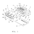
- FIG. 2 is another exploded perspective view of the electrical connector of an embodiment of the present invention and a circuit board, wherein the securing part has been assembled to the base plate of the insulating seat;
- FIG. 3 is an assembly perspective view of the electrical connector of an embodiment of the present invention and a circuit board;
- FIG. 4 is an assembly perspective view of the electrical connector of an embodiment of the present invention and a circuit board from another angle;
- FIG. 5 is a front view of the electrical connector of an embodiment of the present invention and a circuit board following assembly
- FIG. 6 is a side view of the electrical connector of an embodiment of the present invention and a circuit board following assembly.
- One benefit of the concepts disclosed is the ability to provide an electrical connector that can effectively guard against deformation and shifting of the cage when there is a considerable height difference between the cage and the circuit board. Compared to existing technologies, such an electrical connector can provide certain beneficial technical results.
- a connector can employ a securing part to press and attach the base plate of the insulating seat to the circuit board, and the two locking arms at the front of the cage are also fixed to the base plate of the insulating seat.
- This provides a mode in which the cage is locked to the base plate of the insulating seat using locking arms, and the insulating seat is fixed to the circuit board using a securing part in place of the structure employed by existing electrical connectors in which soldering arms at the front of the cage are directly soldered to the circuit board. Because the length of the securing part's locking arms is not limited, it is possible to fix the front portion of the cage when there is a considerable height difference between the bottom wall of the cage and the circuit board, guarding against deformation and shifting of the cage.
- the top surface of the insulating seat's base plate is equipped with step portions that are low in front and high in back, and the back end of the securing part's main body presses against these step portions, thus preventing the forward longitudinal shift of the insulating seat when another mating cable connector (not shown) is being unplugged.
- the main body of the securing part By designing the main body of the securing part to comprise multiple compression portions and bent portions arranged between neighboring compression portions, the shape of the bent portions corresponds to the grooves, and they press into the grooves in the base plate of the insulating seat, thus guarding against the lateral shift of the insulating seat to the left and right when another mating cable connector (not shown) is being plugged and unplugged.
- the locking arms By placing a longitudinal fastening groove along each of the two side surfaces of the insulating seat's base plate, with a wide open front end, the locking arms can be slid in from the front end and locked inside these fastening grooves, for fast assembly of the cage and insulating seat.
- an electrical connector comprises an insulating seat 1 , a plurality of conductive terminals 2 inserted on the insulating seat 1 , and a cage 3 and securing part 4 installed on the insulating seat 1 .
- This electrical connector can be soldered and attached to a circuit board 5 .
- the insulating seat 1 comprises a body 11 and a tongue plate 12 and base plate 13 extending longitudinally forward from the body 11 .
- Each of the two sides on top of the back end of the body 11 has a stop block 111 .
- the tongue plate 12 is a bottom opening frame that can prevent the reverse insertion of another cable connector (not shown), and the top and bottom surfaces of the tongue plate 12 have a number of terminal grooves 121 running longitudinally.
- the base plate 13 is made by the body 11 as it extends forward longitudinally, the base plate 13 is parallel to the tongue plate 12 and located below the tongue plate 12 , and there is a certain gap between it and the tongue plate 12 .
- the top surface 131 of this base plate 13 has three step portions 132 that are low in front and high in back and are separated from each other by lateral gaps, as well as two grooves 135 running longitudinally between neighboring step portions 132 .
- the front of each of the two outer side surfaces of the base plate 13 has a fastening groove 134 running longitudinally, and the front end of the fastening groove 134 is wide open and has a lead-in ramp 1341 .
- the insulating seat 1 also comprises a terminal block 14 (see FIG. 4 ) situated at the back end of the body 11 .
- This terminal block 14 has two rows of through-holes 141 to link top and bottom.
- Each conductive terminal 2 comprises a mating end 21 for connecting electrically to another mating cable connector (not shown) and a soldering end 22 for connecting electrically to the circuit board 5 .
- the mating ends 21 of these conductive terminals 2 are lined up in two top and bottom rows, and they extend forward longitudinally to be contained within the terminal grooves 121 on the top and bottom surfaces of the tongue plate 12 .
- the soldering ends 22 of the multiple conductive terminals 2 are lined up in two front and back rows, and they extend downward through and are fixed within the through-holes 141 of the terminal block 14 , in order to ensure that the soldering ends 22 of the conductive terminals 2 do not come into contact with each other, which would result in a signal transmission failure.
- the cage 3 uses a top wall 31 , two side walls 32 , and a bottom wall 33 to form an enclosure and make a holding cavity 34 to contain the insulating seat 1 .
- the top wall 31 and two side walls 32 of this cage 3 connect with the outer sides of the insulating seat 1 and press up against the stop blocks 111 at the back end of the insulating seat 1 .
- the bottom wall 33 of the cage 3 is situated between the tongue plate 12 and base plate 13 of the insulating seat 1 . In this way, the insulating seat 1 is partially enclosed within the cage 3 .
- Each of the two side walls 32 bend and extend out from their back edges into fastening parts 321 that are fastened to the back end of the insulating seat 1 in order to prevent the insulating seat 1 from separating backward from the cage 3 when another mating cable connector (not shown) is inserted.
- Each of the two side walls 32 extend downward from their back bottom edges into soldering arms 322 , to be soldered to the circuit board 5 .
- At the front of the cage 3 where the two side walls 32 and bottom wall 33 meet, they are processed by stamping to form two locking arms 323 that first bend downward then inward, and there are two corresponding openings 324 in the cage 3 .
- These two locking arms 323 can be locked inside the corresponding fastening grooves 134 on the two sides of the cage's 1 base plate 13 .
- the securing part 4 is laterally constructed on the top surface 131 of the insulating seat's 1 base plate 13 , and it is located between the locking arms 323 of the cage 1 and the step portions 132 of the insulating seat's 1 base plate 13 .
- This securing part 4 is a metal part that has been stamped and bent, and it comprises a main body 41 and two soldering portions 42 bending and extending downward from the two ends of the main body 41 to the outer sides of the insulating seat's 1 base plate 13 .
- This main body 41 comprises three compression portions 411 and two bent portions 412 situated between neighboring compression portions 411 and protruding downward.
- the main body 41 is pressed against the top of the insulating seat's 1 base plate 13 , and the back ends of the three compression portions 411 press up against the front edge of the step portions 132 , in order to prevent forward longitudinal shifting of the insulating seat 1 when another mating cable connector (not shown) is being unplugged.
- the shape of the two bent portions 412 corresponds to the grooves 135 on the insulating seat 1 , and they press into the grooves 135 , thus guarding against the lateral shift of the insulating seat to the left and right when another mating cable connector (not shown) is being plugged and unplugged.
- the top surface of the circuit board 5 has two front positioning holes 51 corresponding to the two soldering portions 42 of the securing part 4 , two rear positioning holes 52 corresponding to the two soldering arms 322 of the cage 3 , and multiple soldering holes 53 corresponding to the soldering ends 22 of the conductive terminals 2 .
- the electrical connector employs a securing part 4 to attach the base plate 13 of the insulating seat 1 to the circuit board 5 , and the two locking arms 323 on the front of the cage 3 are locked to the two sides of the insulating seat's 1 base plate 13 .
- the depicted connector introduces a securing part 4 ; because the soldering portion 42 of the securing part 4 is not limited by the size of the connector's port, the length of the soldering portion 42 is unlimited; thus, it is possible to effectively attach the front portion of the cage 3 when there is a considerable height difference between the bottom surface of the cage's 3 bottom wall 33 and the top surface of the circuit board 5 , guarding against deformation and shifting of the cage 3 , which would make it impossible to normally insert and remove another mating cable connector (not shown).
Landscapes
- Details Of Connecting Devices For Male And Female Coupling (AREA)
- Coupling Device And Connection With Printed Circuit (AREA)
Applications Claiming Priority (4)
| Application Number | Priority Date | Filing Date | Title |
|---|---|---|---|
| CN200910179461.9 | 2009-10-20 | ||
| CN200910179461 | 2009-10-20 | ||
| CN 200910179461 CN102044767B (zh) | 2009-10-20 | 2009-10-20 | 电连接器 |
| PCT/CN2010/001644 WO2011047539A1 (zh) | 2009-10-20 | 2010-10-20 | 电连接器 |
Publications (2)
| Publication Number | Publication Date |
|---|---|
| US20120289077A1 US20120289077A1 (en) | 2012-11-15 |
| US8851928B2 true US8851928B2 (en) | 2014-10-07 |
Family
ID=43899791
Family Applications (1)
| Application Number | Title | Priority Date | Filing Date |
|---|---|---|---|
| US13/503,269 Active 2031-07-10 US8851928B2 (en) | 2009-10-20 | 2010-10-20 | Electrical connector |
Country Status (4)
| Country | Link |
|---|---|
| US (1) | US8851928B2 (ja) |
| JP (1) | JP5437498B2 (ja) |
| CN (1) | CN102044767B (ja) |
| WO (1) | WO2011047539A1 (ja) |
Cited By (2)
| Publication number | Priority date | Publication date | Assignee | Title |
|---|---|---|---|---|
| US20130323944A1 (en) * | 2010-09-03 | 2013-12-05 | Yazaki Corporation | Connector |
| US20130344734A1 (en) * | 2012-06-20 | 2013-12-26 | Jae Taiwan, Ltd. | Connector and mating connector |
Families Citing this family (5)
| Publication number | Priority date | Publication date | Assignee | Title |
|---|---|---|---|---|
| CN105703158A (zh) * | 2014-11-24 | 2016-06-22 | 富士康(昆山)电脑接插件有限公司 | 电连接器 |
| TWI671957B (zh) * | 2015-07-22 | 2019-09-11 | 英屬開曼群島商鴻騰精密科技股份有限公司 | 電連接器組件 |
| US11417979B2 (en) * | 2017-08-01 | 2022-08-16 | Aptiv Technologies Limited | Shielded electrical connector assembly and method of manufacturing same |
| TWI728525B (zh) * | 2019-10-25 | 2021-05-21 | 立佳興業股份有限公司 | 光學連接器的插座結構及其光學通訊裝置 |
| CN113097786B (zh) * | 2019-12-19 | 2023-10-27 | 上海莫仕连接器有限公司 | 第一电连接器、第二电连接器及电连接器组合 |
Citations (16)
| Publication number | Priority date | Publication date | Assignee | Title |
|---|---|---|---|---|
| JPH08178783A (ja) | 1994-12-26 | 1996-07-12 | Yokogawa Electric Corp | 差圧/圧力伝送器 |
| CN2350895Y (zh) | 1998-09-01 | 1999-11-24 | 鸿海精密工业股份有限公司 | 电连接器 |
| US6398587B1 (en) | 2000-12-29 | 2002-06-04 | Hon Hai Precision Ind. Co., Ltd. | Universal serial bus connector |
| US20040157491A1 (en) * | 2002-12-24 | 2004-08-12 | Tung-Chang Lin | Electrical connector |
| JP3109294U (ja) | 2004-12-13 | 2005-05-19 | 正▲うえ▼精密工業股▲ふん▼有限公司 | シールドを具えたコネクタ |
| US20050186843A1 (en) * | 2004-02-20 | 2005-08-25 | Wen-Hsien Tsai | HDMI connector |
| US6962510B1 (en) | 2004-08-05 | 2005-11-08 | Hon Hai Precision Ind. Co., Ltd. | Electrical connector having improved structure regarding terminals |
| US7351105B2 (en) | 2005-11-09 | 2008-04-01 | Molex Incorporated | Board mounted shielded electrical connector |
| TWM350109U (en) | 2008-06-16 | 2009-02-01 | Hon Hai Prec Ind Co Ltd | Electrical connector |
| CN201230018Y (zh) | 2008-05-29 | 2009-04-29 | 富士康(昆山)电脑接插件有限公司 | 电连接器 |
| TWM359832U (en) | 2008-11-10 | 2009-06-21 | Hon Hai Prec Ind Co Ltd | Electrical connector |
| US7575466B2 (en) | 2007-03-02 | 2009-08-18 | Ddk Ltd. | Electrical connector |
| CN201303149Y (zh) | 2008-10-15 | 2009-09-02 | 富士康(昆山)电脑接插件有限公司 | 电连接器 |
| US7901221B1 (en) * | 2009-01-09 | 2011-03-08 | Amazon Technologies, Inc. | Universal serial bus ground clip |
| US8460034B2 (en) * | 2008-12-22 | 2013-06-11 | Molex Incorporated | Miniature electrical connector |
| US8568172B1 (en) * | 2012-04-12 | 2013-10-29 | Cheng Uei Precision Industry Co., Ltd. | Electrical connector |
Family Cites Families (3)
| Publication number | Priority date | Publication date | Assignee | Title |
|---|---|---|---|---|
| CN101350470A (zh) * | 2007-07-19 | 2009-01-21 | 富士康(昆山)电脑接插件有限公司 | 电连接器及其制造方法 |
| CN201112961Y (zh) * | 2007-09-21 | 2008-09-10 | 莫列斯公司 | 电连接器 |
| CN201238107Y (zh) * | 2007-10-09 | 2009-05-13 | 番禺得意精密电子工业有限公司 | 电连接器组件 |
-
2009
- 2009-10-20 CN CN 200910179461 patent/CN102044767B/zh not_active Expired - Fee Related
-
2010
- 2010-10-20 JP JP2012534519A patent/JP5437498B2/ja not_active Expired - Fee Related
- 2010-10-20 WO PCT/CN2010/001644 patent/WO2011047539A1/zh active Application Filing
- 2010-10-20 US US13/503,269 patent/US8851928B2/en active Active
Patent Citations (16)
| Publication number | Priority date | Publication date | Assignee | Title |
|---|---|---|---|---|
| JPH08178783A (ja) | 1994-12-26 | 1996-07-12 | Yokogawa Electric Corp | 差圧/圧力伝送器 |
| CN2350895Y (zh) | 1998-09-01 | 1999-11-24 | 鸿海精密工业股份有限公司 | 电连接器 |
| US6398587B1 (en) | 2000-12-29 | 2002-06-04 | Hon Hai Precision Ind. Co., Ltd. | Universal serial bus connector |
| US20040157491A1 (en) * | 2002-12-24 | 2004-08-12 | Tung-Chang Lin | Electrical connector |
| US20050186843A1 (en) * | 2004-02-20 | 2005-08-25 | Wen-Hsien Tsai | HDMI connector |
| US6962510B1 (en) | 2004-08-05 | 2005-11-08 | Hon Hai Precision Ind. Co., Ltd. | Electrical connector having improved structure regarding terminals |
| JP3109294U (ja) | 2004-12-13 | 2005-05-19 | 正▲うえ▼精密工業股▲ふん▼有限公司 | シールドを具えたコネクタ |
| US7351105B2 (en) | 2005-11-09 | 2008-04-01 | Molex Incorporated | Board mounted shielded electrical connector |
| US7575466B2 (en) | 2007-03-02 | 2009-08-18 | Ddk Ltd. | Electrical connector |
| CN201230018Y (zh) | 2008-05-29 | 2009-04-29 | 富士康(昆山)电脑接插件有限公司 | 电连接器 |
| TWM350109U (en) | 2008-06-16 | 2009-02-01 | Hon Hai Prec Ind Co Ltd | Electrical connector |
| CN201303149Y (zh) | 2008-10-15 | 2009-09-02 | 富士康(昆山)电脑接插件有限公司 | 电连接器 |
| TWM359832U (en) | 2008-11-10 | 2009-06-21 | Hon Hai Prec Ind Co Ltd | Electrical connector |
| US8460034B2 (en) * | 2008-12-22 | 2013-06-11 | Molex Incorporated | Miniature electrical connector |
| US7901221B1 (en) * | 2009-01-09 | 2011-03-08 | Amazon Technologies, Inc. | Universal serial bus ground clip |
| US8568172B1 (en) * | 2012-04-12 | 2013-10-29 | Cheng Uei Precision Industry Co., Ltd. | Electrical connector |
Non-Patent Citations (1)
| Title |
|---|
| International Search Report for PCT/CN2010/001644, Apr. 20, 2012. |
Cited By (4)
| Publication number | Priority date | Publication date | Assignee | Title |
|---|---|---|---|---|
| US20130323944A1 (en) * | 2010-09-03 | 2013-12-05 | Yazaki Corporation | Connector |
| US9136623B2 (en) * | 2010-09-03 | 2015-09-15 | Yazaki Corporation | Connector |
| US20130344734A1 (en) * | 2012-06-20 | 2013-12-26 | Jae Taiwan, Ltd. | Connector and mating connector |
| US9088095B2 (en) * | 2012-06-20 | 2015-07-21 | Japan Aviation Electronics Industry, Limited | Connector and mating connector |
Also Published As
| Publication number | Publication date |
|---|---|
| WO2011047539A1 (zh) | 2011-04-28 |
| JP5437498B2 (ja) | 2014-03-12 |
| JP2013508897A (ja) | 2013-03-07 |
| CN102044767A (zh) | 2011-05-04 |
| CN102044767B (zh) | 2013-06-05 |
| US20120289077A1 (en) | 2012-11-15 |
Similar Documents
| Publication | Publication Date | Title |
|---|---|---|
| US7252549B2 (en) | Connector, receptacle for connector and plug for connector | |
| US7074085B2 (en) | Shielded electrical connector assembly | |
| US8851928B2 (en) | Electrical connector | |
| US7857665B2 (en) | Electrical connector with improved contact arrangement | |
| US6343951B1 (en) | Electrical connector | |
| US8021187B2 (en) | Electric connector | |
| US7086889B2 (en) | Interlocking member for an electrical connector | |
| US7736154B2 (en) | Board to board connector | |
| US7210965B1 (en) | Cable connector assembly | |
| JP5683284B2 (ja) | 基板接続用端子 | |
| KR20180077069A (ko) | 전기 커넥터 | |
| US7377821B2 (en) | Electrical connector | |
| JP3134262U (ja) | 表面実装型コネクタ | |
| JP5315912B2 (ja) | 多連装電気コネクタ | |
| JP2007128876A (ja) | 電気コネクタ | |
| KR20070032896A (ko) | 전선 접속용 커넥터 | |
| JP4623735B2 (ja) | コネクタ | |
| US7985080B2 (en) | Electrical connector having auxiliary hold-down arrangement | |
| US20070077823A1 (en) | Shielded electrical connector for camera module | |
| US11031709B2 (en) | Electrical connector for circuit boards and mounting arrangement for electrical connector for circuit boards | |
| US7309254B2 (en) | Connector which can be increased in holding strength with respect to a substrate | |
| JP2008147020A (ja) | 電気コネクタ及びその組立体、並びに電気コネクタの組立方法 | |
| JP2006269107A (ja) | コネクタ | |
| US7980864B2 (en) | Connector for flexible printed circuit board | |
| JP2007128875A (ja) | 電気コネクタ |
Legal Events
| Date | Code | Title | Description |
|---|---|---|---|
| STCF | Information on status: patent grant |
Free format text: PATENTED CASE |
|
| MAFP | Maintenance fee payment |
Free format text: PAYMENT OF MAINTENANCE FEE, 4TH YEAR, LARGE ENTITY (ORIGINAL EVENT CODE: M1551) Year of fee payment: 4 |
|
| MAFP | Maintenance fee payment |
Free format text: PAYMENT OF MAINTENANCE FEE, 8TH YEAR, LARGE ENTITY (ORIGINAL EVENT CODE: M1552); ENTITY STATUS OF PATENT OWNER: LARGE ENTITY Year of fee payment: 8 |
|
| AS | Assignment |
Owner name: MOLEX, LLC, ILLINOIS Free format text: CHANGE OF NAME;ASSIGNOR:MOLEX INCORPORATED;REEL/FRAME:065020/0733 Effective date: 20150819 Owner name: MOLEX INCORPORATED, ILLINOIS Free format text: ASSIGNMENT OF ASSIGNORS INTEREST;ASSIGNOR:HE, HUA;REEL/FRAME:064991/0650 Effective date: 20120628 |