US8833878B2 - Drawer guide rail system - Google Patents
Drawer guide rail system Download PDFInfo
- Publication number
- US8833878B2 US8833878B2 US13/702,406 US201113702406A US8833878B2 US 8833878 B2 US8833878 B2 US 8833878B2 US 201113702406 A US201113702406 A US 201113702406A US 8833878 B2 US8833878 B2 US 8833878B2
- Authority
- US
- United States
- Prior art keywords
- rail
- driver
- guide
- sliding member
- closing
- Prior art date
- Legal status (The legal status is an assumption and is not a legal conclusion. Google has not performed a legal analysis and makes no representation as to the accuracy of the status listed.)
- Expired - Fee Related, expires
Links
Images


Classifications
-
- A47B88/14—
-
- A—HUMAN NECESSITIES
- A47—FURNITURE; DOMESTIC ARTICLES OR APPLIANCES; COFFEE MILLS; SPICE MILLS; SUCTION CLEANERS IN GENERAL
- A47B—TABLES; DESKS; OFFICE FURNITURE; CABINETS; DRAWERS; GENERAL DETAILS OF FURNITURE
- A47B88/00—Drawers for tables, cabinets or like furniture; Guides for drawers
- A47B88/40—Sliding drawers; Slides or guides therefor
- A47B88/483—Sliding drawers; Slides or guides therefor with single extensible guides or parts
- A47B88/487—Sliding drawers; Slides or guides therefor with single extensible guides or parts with rollers, ball bearings, wheels, or the like
-
- A—HUMAN NECESSITIES
- A47—FURNITURE; DOMESTIC ARTICLES OR APPLIANCES; COFFEE MILLS; SPICE MILLS; SUCTION CLEANERS IN GENERAL
- A47B—TABLES; DESKS; OFFICE FURNITURE; CABINETS; DRAWERS; GENERAL DETAILS OF FURNITURE
- A47B88/00—Drawers for tables, cabinets or like furniture; Guides for drawers
- A47B88/40—Sliding drawers; Slides or guides therefor
- A47B88/49—Sliding drawers; Slides or guides therefor with double extensible guides or parts
- A47B88/493—Sliding drawers; Slides or guides therefor with double extensible guides or parts with rollers, ball bearings, wheels, or the like
-
- A47B88/047—
-
- A—HUMAN NECESSITIES
- A47—FURNITURE; DOMESTIC ARTICLES OR APPLIANCES; COFFEE MILLS; SPICE MILLS; SUCTION CLEANERS IN GENERAL
- A47B—TABLES; DESKS; OFFICE FURNITURE; CABINETS; DRAWERS; GENERAL DETAILS OF FURNITURE
- A47B88/00—Drawers for tables, cabinets or like furniture; Guides for drawers
- A47B88/40—Sliding drawers; Slides or guides therefor
- A47B88/453—Actuated drawers
- A47B88/46—Actuated drawers operated by mechanically-stored energy, e.g. by springs
- A47B88/467—Actuated drawers operated by mechanically-stored energy, e.g. by springs self-closing
-
- A—HUMAN NECESSITIES
- A47—FURNITURE; DOMESTIC ARTICLES OR APPLIANCES; COFFEE MILLS; SPICE MILLS; SUCTION CLEANERS IN GENERAL
- A47B—TABLES; DESKS; OFFICE FURNITURE; CABINETS; DRAWERS; GENERAL DETAILS OF FURNITURE
- A47B2210/00—General construction of drawers, guides and guide devices
- A47B2210/0091—Drawer movement damping
Definitions
- This invention relates to a drawer guide rail system.
- this invention relates to a drawer guide rail system having a closing device to aid in the drawer closing motion and a damping device for deceleration of a drawer closing motion.
- Drawer guide rails are components in common every day use, such as for drawers in desks or cabinets, and for industrial use such as pull out storage shelves at a warehouse, cash registers at a supermarket, automated teller machines at banking kiosks, electronic equipment at telephone switching stations and so on.
- Guide rail systems are provided for drawers to be either partially or fully opened or closed and typically consist of a bracket for fixing the system to the article of furniture, a fixed rail mounted on the bracket, a pull-out rail attached to the side of the drawer, and preferably an intermediate rail in between the fixed and pull-out rails.
- the intermediate rail is slidable over the fixed rail and the pull-out rail is slidable over the intermediate rail normally due to slidable roller housings disposed within the fixed and pull-out rails.
- Each of the fixed, intermediate and pull-out rails is also normally disposed with pairs of limit stoppers. The distance traveled by the slidable roller housings between each pair of limit stoppers on each rail element typically defines the travel distance of each rail.
- a guide rail assembly that incorporates a closing device to aid in the drawer-closing motion and allows for aided and controlled decelerated closing motion of a drawer was developed and disclosed in Malaysian utility innovation application no. UI 20093357.
- a mounting bracket having a fixed rail, an intermediate rail and an outer pull out rail is provided.
- roller housings are provided so as to enable the intermediate rail and outer pull out rail to be slidable.
- a protrusion and a guiding pin is provided on the bottom surface of the outer pull-out rail.
- a fluid damper and a channel guide having a sliding member are disposed end-to-end on the mounting bracket, the sliding member being contactable by the pull out rail protrusion.
- a distal end of the damper rod is located within the sliding member.
- a closing device is provided on the mounting bracket adjacent its fixed rail.
- the closing device comprises an elongate hollow housing, a locking step, a rotating member slidably mounted in the front portion of the housing and a resilient means mounted in the rear portion of the housing and coupled to the rotating member.
- the rotating member has an angular slot to receive the guiding pin of the pull out rail.
- the outer pull out rail is caused to slide in a drawer-closing direction.
- the pull out rail protrusion reaches and engages with the sliding member.
- the guiding pin engages with the angular slot of the closing device rotating member.
- further closing of the pull out rail (drawer) is aided by the closing device.
- the rotating member is anchored at its locking step, in front of its housing, when engaged by the guiding pin.
- Action of the guiding pin within the angular slot causes rotation of the rotating member, which frees it from its locking step and allows it to be pulled axially through the housing by the resilient means.
- the rotating member is prevented from rotating during axial movement. Engagement of the pull out rail protrusion with the sliding member urges it to travel within the channel guide against the resilience of the fluid damper, hence, causing deceleration of the drawer-closing motion.
- the closing device of this prior assembly periodically fails, when it is used with a large and/or heavily loaded drawer, and especially when excessive force is used in pushing in the drawer.
- the successful function of the closing device of this prior assembly is dependent on accurate insertion of the pull out rail guiding pin within its rotating member angular slot. Any inaccuracy in that insertion, either due to manufacturing irregularities, assembly error and/or excessive drawer closing force, will result in failure of the closing device.
- This invention thus aims to alleviate some or all of the problems of the prior design.
- a guide rail system for slidably opening and closing a drawer within an enclosure.
- the system comprises a mounting bracket for fixing the system to the enclosure, the mounting bracket having a fixed rail for receiving an intermediate rail; an intermediate rail capable of sliding back and forth relative to the mounting bracket fixed rail; and a pull out rail for attachment to the drawer and being capable of sliding back and forth on the intermediate rail.
- the pull out rail has a guiding pin on its bottom surface.
- a damping device and a channel guide are disposed along the mounting bracket.
- the damping device is resiliently compressible in a lengthwise direction and the channel guide has a sliding member adapted to travel along the channel guide and locate an end of the damping device that can be pushed inwardly to provide damping.
- a closing device is disposed along the mounting bracket, and comprises a housing, a resilient means disposed within the housing, and a driver pivotally mounted with the housing and operatively connected to the resilient means.
- the driver is pivotable between a first locked position and a second linearly moveable position, and includes an angular slot for receiving the guiding pin and an abutment projection contactable with the sliding member.
- the pull out rail is caused to slide in a drawer-closing direction.
- the action of the guiding pin within the angular slot causes the driver to be pivoted from its first position to its second position where the abutment projection engages with the sliding member.
- the driver further comprises a resilient tongue contactable with the guiding pin when the driver is caused to pivot from its first position to its second position without engagement of the pin within the angular slot.
- the damping device may comprise a cylinder body and a rod that is pushable into the cylinder body when the device is compressed with the distal end of the rod being located in the sliding member.
- the damping device may be a fluid damper.
- the channel guide has an open top such that the sliding member extends through the open top of the channel guide and locates an end of the damping device through a longitudinal end of the channel.
- the sliding member may further comprise a chamber for receiving the end of the damping device.
- the sliding member may further comprise an abutment face contactable with the abutment projection of the closing device driver.
- the aperture and abutment face may be disposed on opposing ends of the sliding member.
- the closing device may be disposed to a side of the damping device and channel guide, on the mounting bracket.
- the closing device housing may be C-shaped and comprise of a pair of side flanges and a top flange.
- a bracket may be provided on one of the side flanges for removably attaching the damping device to the closing device.
- the closing device housing may further comprise a recess for receiving the driver.
- the recess may be provided with a lip portion and the driver may be provided with a corresponding hook portion engageable with the lip portion, to lock the driver in its first position.
- the driver may further comprise a catch for receiving an end of the resilient means. Both the catch and the end of the resilient means received therein are suitably shaped so as to enable the driver to be pivotable about that point.
- the driver may further comprise a guide groove, with a housing side flange insertable within the groove, in use, for guiding the pivoting movement of the driver.
- the driver may further comprise a resilient tongue contactable with the pull out rail guiding pin, in use.
- the intermediate rail may comprise a C-shaped guide that is slidable along the mounting bracket fixed rail and a channel piece disposed on top of the C-shaped guide, whereby the pull out rail is slidable along the channel piece of the intermediate rail.
- the fixed rail and pull out rail each may further comprise a slidable housing having a plurality of rollers that enables the intermediate rail to be slidable on the fixed rail and the pull out rail to be in turn slidable on the intermediate rail.
- the objective of the drawer guide rail system of this invention is to provide a reliably aided, quiet, controlled and decelerated drawer-closing motion with a system of a sufficiently robust design to withstand excessive drawer-closing force without the need for frequent replacements of drawer or guide rail elements.
- closing device guide rail system
- the closing device to be highly tolerant of manufacturing irregularities and/or assembly errors, since as mentioned above its function is no longer dependent on insertion (accurate or otherwise) of the pull out rail guiding pin into the angular slot.
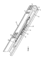
- FIG. 1 shows a perspective view of a sliding guide rail system according to an embodiment of this invention, in a partially extended position.
- FIG. 2 is a perspective view of the assembly of FIG. 1 (the pull out rail, and intermediate rail has been removed to show the interaction between the damping device, channel guide, sliding member and closing device).
- FIG. 3 shows the assembly of FIG. 2 , in a fully retracted position (drawer fully closed).
- FIG. 4 shows the closing device, damping device and channel guide of FIG. 1 , as assembled.
- FIG. 5 is an exploded view of the closing device, damping device and channel guide of FIG. 4 .
- FIGS. 6A and 6B show front and rear views of the driver of the closing device of FIG. 1 .
- FIGS. 7A and 7B show front and rear views of the sliding member of the channel guide of FIG. 1 .
- FIG. 8 shows a top view of the assembly of the embodiment of FIG. 1 as the drawer is initially in a fully opened position and subsequently pushed into a fully closed position.
- FIGS. 1 to 8 show an embodiment of a drawer guide rail system according to the present invention.
- This guide rail system comprises of a mounting bracket 10 for fixing the drawer to the article of furniture, the mounting bracket 10 having a fixed rail 15 , an intermediate rail 20 and a pull out rail 30 secured to the drawer.
- the fixed rail 15 and pull out rail 30 each have a slidable housing (not shown) having a plurality of rollers, which enables the intermediate rail 20 to be slidable on the fixed rail 15 and the pull out rail 30 to be in turn slidable on the intermediate rail 20 .
- a damping device 40 and a channel guide 50 with sliding member 55 are mounted on and along the mounting bracket 10 adjacent the fixed rail 15 .
- a closing device 60 which comprises of a housing 70 , a resilient means 80 and a pivotable driver 90 that operatively interacts with the sliding member 55 (channel guide 50 ) and damping device 40 to initiate deceleration of the drawer closing motion.
- the mounting bracket 10 is formed from sheet metal into an L-section with the upper free edge of the horizontal flange 11 of the L-section bent upwardly to form a fixed rail 15 having a running surface for the sliding housings (described below).
- the height of the fixed rail 15 is significantly less than the height of the vertical flange 12 of the L-section mounting bracket.
- the fixed rail 15 also has a folded up metal tab at its rear longitudinal end (relative to drawer orientation) that functions as a limit stopper for the sliding housing (described below) that slides thereon.
- the vertical flange 12 of the mounting bracket 10 is provided with a multitude of holes 13 for fixing to the side of an article of furniture, and has stepped edges formed thereon and notches at the bent edge of the L-section for increasing the rigidity and load capacity of the bracket 10 .
- the mounting bracket 10 When in use, the mounting bracket 10 bears the whole weight of the drawer load.
- the fixed rail 15 will be subjected to tremendous load force when a drawer is heavily loaded.
- several strengthening corner settings 14 are preferably added at the adjoining portion of the vertical and horizontal flanges 12 , 11 of the mounting bracket 10 .
- the damping device 40 and channel guide 50 with sliding member 55 are longitudinally mounted on the horizontal flange 11 of the mounting bracket 10 adjacent the fixed rail 15 . Also mounted on the mounting bracket 10 is a closing device 60 .
- a stopper tab (not shown) is provided on the horizontal flange 11 of the L-section adjacent and between the channel guide 50 and fixed rail 15 . The stopper tab is located such that it is forward relative to the rear travel limit position of the sliding member 55 within the channel guide 50 .
- the intermediate rail 20 seen in FIG. 1 consists of an open C-shaped guide 21 having unequal sides that is slidable along the mounting bracket fixed rail 15 and a channel piece 22 disposed on top of the C-shaped guide 21 .
- a punched out tab (not shown) that extends inwards and serves as a travel limit stopper for the fixed rail sliding housing (not shown).
- the channel piece 22 is preferably a substantially planar metal plate that is detachably mounted on top of the C-shaped guide 21 and slidably receives the pull out rail 30 thereon.
- the channel piece 22 has a step on each side, thereby defining a shoulder on each side of the channel piece 22 , for guiding and stabilizing the sliding motion of the pull out rail 30 .
- the width of this channel piece 22 is therefore, preferably considerably more than that of the C-shaped guide 21 but slightly less than that of the pull out rail 30 .
- a punched out tab functioning as a limit stopper for the sliding housing of the pull out rail 30 is also provided at the upper end of the channel piece 22 .
- the pull out rail 30 is formed from a sheet metal into an open C-section.
- On either side of this pull out rail 30 are two stops 31 disposed such that each stop 31 is located towards a longitudinal end of the rail 30 .
- These stops 31 consist of punched-out tabs that bend inwardly.
- An L-shaped extension 32 is cut or formed on the upper surface of this pull out rail 30 . This extension 32 engages with an aperture (not shown) at the back of the drawer for fixing the pull out rail 30 to the drawer.
- An aperture (not shown) is also punched on the side of this pull out rail 30 at the front end (relative to drawer orientation) to allow for engagement with a catch (not shown) mounted on the bottom of the drawer.
- Slidably fitted inside this pull out rail 30 is a sliding housing (not shown) having rollers which allows it to run smoothly inside the pull out rail 30 between the stops.
- a guiding pin 35 for engagement with the closing device 60 (driver 90 ) is provided on the bottom surface of the pull out rail 30 .
- This pull out rail 30 comprises an open space formed by bending a side portion of the rail top surface downwards.
- a cut-in recess 33 is provided on the other side of the pull out rail front end.
- An opening is provided on the top surface of the rail, adjacent the bent-down portion, for receiving an attachment tab of the stopper piece 34 which will be described below.
- a stopper piece 34 is provided on the bottom surface, toward the front end (relative to drawer orientation), of the pull out rail 30 .
- the stopper piece 34 is preferably removably mounted on the bottom surface of the rail 30 .
- the stopper piece 34 comprises a pair of attachment tabs on its top and the bottom surface at a front end of the pull out rail 30 has a pair of corresponding apertures for receiving the stopper piece attachment tabs.
- the stopper piece 34 is a substantially rectangular block with its rear longitudinal end comprising an abutment surface. The abutment surface is engagable with the mounting bracket stopper tab. Engagement of the abutment surface of the stopper piece with the stopper tab defines the rear travel limit of the pull out rail 30 .
- the sliding housings (not shown) of both the fixed rail 15 and pull out rail 30 are of a similar construction and comprise a long member having a substantially rectangular cross-section with a hollow central recess. Rollers are provided at the upper part and both sides of the recess. The side rollers are vertically displaced by a distance substantially equal to the thickness of the vertical web of the intermediate rail. The number, type (whether upper or side rollers) and configuration of rollers depend on the load capacity for which the sliding housings are designed. Further side rollers (not shown) that provide lateral guidance for the drawer/equipment may also be provided, wherein when these rollers are spaced as far apart as possible, greater lateral stability is provided.
- the open recess of the intermediate rail-sliding housing enables the intermediate rail 20 to be slidable on the fixed rail 15 with the lower flange of the rail slidably fitted therein.
- the open T-shaped recess of the pull out rail-sliding housing enables the pull out rail 30 to be slidable on the intermediate rail 20 with the upper flange of the rail slidably fitted therein.
- Adequate clearances are provided between the upper rollers and the respective contact surfaces of both the upper and lower flanges of the intermediate rail 20 for ease of alignment and/or assembly.
- adequate clearances are provided between side rollers and the contact surfaces of the vertical web of the intermediate rail 20 .
- Both the damping device 40 and channel guide 50 with sliding member 55 are located longitudinal end to longitudinal end relative to each other with the damping device 40 in a rear position and the channel guide 50 in a front position, both rear and front positions being relative to drawer orientation within the article.
- a punched out metal tab with aperture and slots (not shown) is provided on the horizontal flange 11 of the mounting bracket 10 to aid in firmly holding the damping device 40 and channel guide 50 .
- the damping device 40 ( FIGS. 4 and 5 ) is resiliently compressible in a lengthwise direction and comprises a cylinder body 41 with a rod 42 that is pushable into the cylinder body 41 when the device is compressed.
- the damping device 40 is oriented such that the distal end of the rod 42 is locatable in the sliding member 55 of the channel guide 50 .
- a pair of attachment brackets 45 is provided on the longitudinal ends of the cylinder body 41 with the rear bracket having a protruding tab for engagement with the mounting bracket metal tab and aperture, and the front bracket being engagable with a side bracket 75 of the closing device housing 70 .
- a fluid damper is preferred for use with the assembly of this invention, the damping device 40 may also easily comprise an air damper.
- the channel guide 50 ( FIGS. 4 and 5 ) is a substantially rectangular elongate channel with an open top.
- the channel portion 51 of the guide 50 is of uniform width throughout its length.
- a longitudinal end of the channel portion 51 faces the rod 42 of the damping device 40 .
- Attachment means (not shown) provided on the bottom of the guide 50 is engaged into corresponding receiving apertures (not shown) on the horizontal flange 11 of the mounting bracket 10 .
- the channel guide 50 is thus, firmly mounted on the mounting bracket 10 .
- the sliding member 55 comprises a lower portion 56 and an upper portion 57 .
- the lower portion 56 of the sliding member 55 is slidably mounted within, and, is slidable along the channel portion 51 of the guide 50 .
- the upper portion 57 of the sliding member 55 extends through the open top of the guide 50 .
- the rear face of the sliding member upper portion 57 is provided with a chamber 58 for receiving the distal end of the damping device rod 42 .
- the front face of the sliding member upper portion 57 comprises an abutment face 59 engagable with the abutment projection 95 of the closing device driver 90 . When fully extended, the damping device rod 42 runs along the length of the channel portion 51 of the guide 50 .
- a drawer closing device 60 is provided on the mounting bracket horizontal flange 11 , preferably, between its vertical flange 12 and the longitudinal arrangement of the damping device 40 and channel guide 50 .
- the closing device 60 aids in the drawer-closing motion i.e. sliding motion of the pull out rail 30 in a drawer-closing direction, and comprises a housing 70 , a resilient means 80 mounted within the housing 70 , and a driver 90 pivotally mounted with the housing 70 and operatively connected to the resilient means 80 .
- the closing device housing 70 is C-shaped with a pair of side flanges and a top flange 71 .
- the housing 70 is affixed to the mounting bracket 10 by way of upwardly bent tabs provided on the horizontal flange 11 of the mounting bracket 10 .
- the side flange of the housing 70 facing inward of the assembly, adjacent the damping device 40 and channel guide 50 in use, will be termed as the “inner side flange 72 ”.
- a sidewardly protruding bracket 75 is provided on the inner side flange 72 of the housing 70 . This bracket 75 is provided for removable attachment of the damping device 40 (front attachment bracket 45 ) to the housing 70 (closing device 60 ).
- the inner side flange 72 is of a reduced height, forming a step 73 .
- the function of this inner side flange step 73 will be discussed below.
- a portion of the inner side flange 72 forward of the step 73 as well as an adjacent portion of the top flange 71 is cut-out, forming a recess 74 for receiving the driver 90 .
- This recess 74 is located near the front longitudinal end of the housing 70 .
- a lip 76 is provided along a top edge of the recess 74 .
- a corner 77 of the recess is engageable with a portion of the driver 90 , in use, to define the front linear travel limit of the driver 90 .
- the resilient means 80 (preferably a spring) is enclosed within the housing 70 , with its rear longitudinal end 81 mounted in a receiver (not shown) provided at the rear of the housing 70 .
- the front longitudinal end 82 of the resilient means 80 is suitably shaped and loosely fitted within a correspondingly shaped socket 92 (spring catch) provided at a rear corner of the closing device driver 90 such that the driver is pivotable about a horizontal axis
- the pivotable driver 90 ( FIGS. 6A and 6B ) is substantially wedge-shaped with the above-mentioned spring catch 92 provided at one rear corner and an abutment projection 95 provided at the other rear corner.
- the abutment projection 95 has a flat face that contacts and engages the sliding member abutment face 59 , in use.
- a hook 91 is provided forward of the spring catch 92 , along a side of the driver 90 .
- the rear portion 97 of hook 91 is engageable with corner 77 of the housing 70 , in use.
- a resilient tongue 93 is provided on the front of the driver 90 .
- An angular slot 94 is provided on the top surface of the driver 90 for receiving the guiding pin 35 of the pull out rail 30 .
- the abutment projection 95 and spring catch 92 are spaced apart at the rear of the driver 90 such that a guide groove 96 is defined therebetween. This guide groove 96 aids in guiding the pivoting movement of the driver 90 .
- the damping device 40 and channel guide 50 are mounted onto the mounting bracket horizontal flange 11 , adjacent the fixed rail 15 .
- the closing device 60 is separately assembled prior to mounting onto the mounting bracket 10 .
- the front end 82 of the resilient means 80 is firstly inserted into the spring catch 92 of the driver 90 . Subsequently, the resilient means-driver configuration is mounted to the housing 70 with the rear end 81 of the resilient means 80 fixed to the receiver at the rear of the housing 70 , the housing inner side flange 72 inserted within the driver guide groove 96 and the front and side of the driver 90 fitted within the housing recess 74 .
- the pivoting movement of the driver 90 about a horizontal axis at its pivot point (spring catch 92 ) is guided by interaction of the inner side flange 72 against the opposing surfaces of the guide groove 96 .
- the degree of movement of the driver 90 about its pivot point is determined by the curvature of the guide groove 96 .
- the driver 90 is locked with the housing 70 by engaging its hook 91 onto the recess lip 76 such that the driver 90 is in its first locked position.
- the closing device housing 70 (with resilient means 80 and driver 90 mounted thereto) is then fixed onto the mounting bracket horizontal flange 11 , to a side of the damping device-channel guide configuration.
- the closing device housing 70 is mounted on the mounting bracket 10 by sliding it rearwardly until the front attachment bracket 45 of the damping device 40 is inserted beneath the side bracket 75 of the closing device housing 70 . In this position, a corner of the driver abutment projection 95 rests against the sliding member abutment face 59 .
- the pull out rail 30 is in a fully extended position and the sliding member 55 is at its front travel limit abutting against the front end of the channel guide 50 .
- the rod 42 of the damping device 40 with its distal end located within the sliding member 55 runs along the length of the channel guide 50 .
- the driver 90 is in its first locked position (hook 91 engaged to recess lip 76 ) and a corner of its abutment projection 95 is resting against the abutment face 59 of the sliding member 55 .
- the pull out rail 30 is caused to slide in a drawer-closing direction as the drawer is pushed in ( FIG. 8 ).
- the guiding pin 35 of the pull out rail 30 will come in contact with the closing device driver 90 at the opening of its angular slot 94 .
- the guiding pin 35 enters the angular slot 94 and the action of the pin 35 within the slot 94 causes the driver 90 to pivot about a horizontal axis, releasing it from its first locked position, to a second position where it is linearly moveable in a rearwardly direction under bias of the resilient means 80 .
- Further rearward movement of the drawer (pull out rail 30 ) causes the guiding pin 35 to be engaged within the angular slot 94 .
- the closing action of the guide rail system (and the drawer) is aided by the action of the closing device 60 .
- the pull out rail 30 sliding motion is halted at its rear travel limit as the abutment surface of its stopper piece 34 engages the stopper tab of the mounting bracket 10 . Due to the location of the mounting bracket stopper tab such that it is forward relative to the rear travel limit position of the sliding member 55 , the sliding member 55 continues to be slidable even though the pull out rail 30 is at its rear travel limit and as such, stationary.
- the rear travel limit of the sliding member 55 is defined by the rear longitudinal end of the channel guide 50 .
- the closing device driver 90 is caused to pivot from its first locked position to its second linearly moveable position, without engagement of the pull out rail guiding pin 35 within its angular slot 94 (e.g. excessive force is exerted onto the guide rail system or human error during assembly).
- the inner side flange step 73 of the closing device housing 70 acts as a rear travel limit (or stopper) for the linear movement of the driver 90 .
- the guiding pin 35 will come into contact with the resilient tongue 93 of the closing device driver 90 .
- the resilient tongue 93 will flex downwards enabling the guiding pin 35 to be engaged within the angular slot 94 .
- the guide rail system (and closing device 60 ) functions as explained above.
- the pull out rail 30 When the drawer is in a fully closed position, the pull out rail 30 is at its rear travel limit with the abutment surface of its stopper piece 34 engaged with the mounting bracket stopper tab and its guiding pin 35 engaged within the angular slot 94 and the closing device driver 90 is in its second position.
- the damping device 40 is in a compressed state (majority length of the rod 42 with its distal end located within the sliding member 55 pushed into cylinder body 41 ) and the sliding member 55 is engaged with the closing device driver 90 (sliding member abutment face 59 fully abuts against the driver abutment projection 95 ).
- the pull out rail 30 is caused to slide in a drawer-opening direction.
- the action of the guiding pin 35 within the angular slot 94 moves the closing device 60 linearly in a drawer opening direction, against the action of the resilient means 80 .
- the damping device 40 decompresses in a lengthwise direction and the rod 42 will be pushed out of its cylinder body 41 .
- the distal end of the rod 42 is located within the sliding member 55 , decompression of the damping device 40 will urge the forward sliding motion of the sliding member 55 within the channel guide 50 .
Landscapes
- Engineering & Computer Science (AREA)
- Mechanical Engineering (AREA)
- Drawers Of Furniture (AREA)
Applications Claiming Priority (3)
| Application Number | Priority Date | Filing Date | Title |
|---|---|---|---|
| MYPI2010003593 | 2010-07-29 | ||
| MYPI2010003593A MY155806A (en) | 2010-07-29 | 2010-07-29 | Drawer guide rail system |
| PCT/MY2011/000056 WO2012015294A1 (en) | 2010-07-29 | 2011-05-24 | Drawer guide rail system |
Publications (2)
| Publication Number | Publication Date |
|---|---|
| US20130076219A1 US20130076219A1 (en) | 2013-03-28 |
| US8833878B2 true US8833878B2 (en) | 2014-09-16 |
Family
ID=45530322
Family Applications (1)
| Application Number | Title | Priority Date | Filing Date |
|---|---|---|---|
| US13/702,406 Expired - Fee Related US8833878B2 (en) | 2010-07-29 | 2011-05-24 | Drawer guide rail system |
Country Status (7)
| Country | Link |
|---|---|
| US (1) | US8833878B2 (ja) |
| EP (1) | EP2597996A4 (ja) |
| JP (1) | JP5911864B2 (ja) |
| CN (1) | CN103327848A (ja) |
| AU (1) | AU2011283259A1 (ja) |
| MY (1) | MY155806A (ja) |
| WO (1) | WO2012015294A1 (ja) |
Cited By (3)
| Publication number | Priority date | Publication date | Assignee | Title |
|---|---|---|---|---|
| US20140363107A1 (en) * | 2011-12-23 | 2014-12-11 | Grass Gmbh | Device for influencing the movement of a furniture part, guide unit for guiding the movement of a furniture part, and item of furniture |
| US20210388656A1 (en) * | 2018-10-14 | 2021-12-16 | Martin Zimmer | Retraction device with spring energy accumulator which can be coupled |
| USD1008793S1 (en) * | 2021-07-20 | 2023-12-26 | Julius Blum Gmbh | Furniture fitting |
Families Citing this family (20)
| Publication number | Priority date | Publication date | Assignee | Title |
|---|---|---|---|---|
| JP2011196015A (ja) * | 2010-03-17 | 2011-10-06 | Nifco Inc | 摺動補助装置 |
| JP5433466B2 (ja) * | 2010-03-17 | 2014-03-05 | 株式会社ニフコ | 摺動補助装置 |
| US20130160240A1 (en) * | 2011-12-23 | 2013-06-27 | Cavity Sliders Limited | Damping Assembly and Damping Mechanism Therefor |
| KR101391247B1 (ko) * | 2012-07-12 | 2014-05-02 | 박윤식 | 자동 폐쇄 장치 |
| ITMI20121718A1 (it) * | 2012-10-12 | 2014-04-13 | Salice Arturo Spa | Mobile con almeno un cassetto o simile |
| CN103510777B (zh) * | 2013-10-23 | 2016-06-15 | 佛山市浪鲸洁具有限公司 | 一种淋浴房的缓冲器安装结构 |
| AT515120B1 (de) * | 2013-12-03 | 2015-06-15 | Blum Gmbh Julius | Antriebsvorrichtung für ein bewegbares Möbelteil |
| DE102013114309A1 (de) * | 2013-12-18 | 2015-06-18 | Paul Hettich Gmbh & Co. Kg | Einzugs- und Dämpfungseinheit für ein Schiebeelement |
| AT14879U1 (de) * | 2014-06-06 | 2016-08-15 | Blum Gmbh Julius | Antriebsvorrichtung für ein bewegbares Möbelteil |
| AT14880U1 (de) * | 2014-07-04 | 2016-08-15 | Blum Gmbh Julius | Ausziehführung für ein bewegbares Möbelteil |
| CN105581535B (zh) * | 2014-10-23 | 2017-12-05 | 川湖科技股份有限公司 | 滑轨总成 |
| DE102015003414B3 (de) * | 2015-03-17 | 2016-06-16 | Günther Zimmer | Kombinierte Beschleunigungs- und Verzögerungsvorrichtung mit Überlastschutz |
| DE202015006279U1 (de) * | 2015-09-04 | 2016-12-07 | Grass Gmbh | Dämpfungsvorrichtung zur Dämpfung der Öffnungsbewegung eines bewegbaren Möbelteils |
| ES2572158B1 (es) * | 2015-11-19 | 2016-11-30 | Adinor, S.L. | Sistema de amortiguación para armarios de puertas correderas |
| US10294706B2 (en) * | 2016-06-30 | 2019-05-21 | Rollmech Automotive Sanayi Ve Ticaret Anonim Sirketi | Sliding door stopper |
| DE102017113862B3 (de) * | 2017-06-22 | 2018-09-20 | Hahn-Gasfedern Gmbh | Endlagedämpfungsvorrichtung und Anordnung mit einer Endlagedämpfungsvorrichtung |
| DE102018008207B4 (de) | 2018-10-14 | 2023-11-09 | Günther Zimmer | Verzögerungsvorrichtung mit mehrteiligem Mitnahmeelement |
| CN109998302A (zh) * | 2019-04-29 | 2019-07-12 | 广东金思达家居配件有限公司 | 一种可随意停的防强脱导轨反弹装置 |
| USD1030461S1 (en) * | 2021-07-20 | 2024-06-11 | Julius Blum Gmbh | Furniture fitting |
| USD986727S1 (en) * | 2021-08-31 | 2023-05-23 | Ashley Furniture Industries, Llc | Drawer guide |
Citations (12)
| Publication number | Priority date | Publication date | Assignee | Title |
|---|---|---|---|---|
| US20030234604A1 (en) * | 2002-06-20 | 2003-12-25 | Nan Juen International Co., Ltd. | Buffer and return device for a slide rail in a drawer |
| US6846053B2 (en) * | 2000-09-19 | 2005-01-25 | Arturo Salice S.P.A. | Grease-dampened drawer closing apparatus |
| US20070101539A1 (en) | 2004-06-18 | 2007-05-10 | Harald Sutterlutti | Device for moving a movable furniture part |
| US20070132346A1 (en) * | 2005-11-07 | 2007-06-14 | Nan Juan International Co., Ltd. | Automatic closing mechanism for a sliding track of a drawer |
| US20070278919A1 (en) * | 2006-06-02 | 2007-12-06 | Gslide Corporation | Hidden type sliding rail assembly auto locking structure for drawer |
| US20070278917A1 (en) * | 2006-06-02 | 2007-12-06 | Jun-Long Yang | Drawer rail |
| US20090230830A1 (en) * | 2008-03-13 | 2009-09-17 | Ng Tai Wai | Drawer Slide Closing Device |
| US20090273129A1 (en) * | 2006-12-11 | 2009-11-05 | Gunther Zimmer | Combined deceleration and acceleration device |
| US20090273263A1 (en) * | 2004-12-17 | 2009-11-05 | Alfit Ag | Closing and Opening Device for Drawers |
| US20090278430A1 (en) * | 2008-05-07 | 2009-11-12 | Hsiu-Chiang Liang | Retraction mechanism for a drawer |
| US20090309470A1 (en) * | 2006-05-24 | 2009-12-17 | Paul Hetitich Gmbh & Co Kg | Closing and retaining device for an extension guide |
| US20100123378A1 (en) | 2008-11-20 | 2010-05-20 | King Slide Works Co., Ltd. | Self-closing rail system |
Family Cites Families (1)
| Publication number | Priority date | Publication date | Assignee | Title |
|---|---|---|---|---|
| CN201379271Y (zh) * | 2009-04-08 | 2010-01-13 | 河北第二机械工业有限公司 | 一种自回闭锁的滑轨 |
-
2010
- 2010-07-29 MY MYPI2010003593A patent/MY155806A/en unknown
-
2011
- 2011-05-24 WO PCT/MY2011/000056 patent/WO2012015294A1/en active Application Filing
- 2011-05-24 EP EP11812821.4A patent/EP2597996A4/en not_active Withdrawn
- 2011-05-24 US US13/702,406 patent/US8833878B2/en not_active Expired - Fee Related
- 2011-05-24 AU AU2011283259A patent/AU2011283259A1/en not_active Abandoned
- 2011-05-24 JP JP2013521730A patent/JP5911864B2/ja not_active Expired - Fee Related
- 2011-05-24 CN CN2011800341602A patent/CN103327848A/zh active Pending
Patent Citations (12)
| Publication number | Priority date | Publication date | Assignee | Title |
|---|---|---|---|---|
| US6846053B2 (en) * | 2000-09-19 | 2005-01-25 | Arturo Salice S.P.A. | Grease-dampened drawer closing apparatus |
| US20030234604A1 (en) * | 2002-06-20 | 2003-12-25 | Nan Juen International Co., Ltd. | Buffer and return device for a slide rail in a drawer |
| US20070101539A1 (en) | 2004-06-18 | 2007-05-10 | Harald Sutterlutti | Device for moving a movable furniture part |
| US20090273263A1 (en) * | 2004-12-17 | 2009-11-05 | Alfit Ag | Closing and Opening Device for Drawers |
| US20070132346A1 (en) * | 2005-11-07 | 2007-06-14 | Nan Juan International Co., Ltd. | Automatic closing mechanism for a sliding track of a drawer |
| US20090309470A1 (en) * | 2006-05-24 | 2009-12-17 | Paul Hetitich Gmbh & Co Kg | Closing and retaining device for an extension guide |
| US20070278919A1 (en) * | 2006-06-02 | 2007-12-06 | Gslide Corporation | Hidden type sliding rail assembly auto locking structure for drawer |
| US20070278917A1 (en) * | 2006-06-02 | 2007-12-06 | Jun-Long Yang | Drawer rail |
| US20090273129A1 (en) * | 2006-12-11 | 2009-11-05 | Gunther Zimmer | Combined deceleration and acceleration device |
| US20090230830A1 (en) * | 2008-03-13 | 2009-09-17 | Ng Tai Wai | Drawer Slide Closing Device |
| US20090278430A1 (en) * | 2008-05-07 | 2009-11-12 | Hsiu-Chiang Liang | Retraction mechanism for a drawer |
| US20100123378A1 (en) | 2008-11-20 | 2010-05-20 | King Slide Works Co., Ltd. | Self-closing rail system |
Cited By (6)
| Publication number | Priority date | Publication date | Assignee | Title |
|---|---|---|---|---|
| US20140363107A1 (en) * | 2011-12-23 | 2014-12-11 | Grass Gmbh | Device for influencing the movement of a furniture part, guide unit for guiding the movement of a furniture part, and item of furniture |
| US9545152B2 (en) * | 2011-12-23 | 2017-01-17 | Grass Gmbh | Device for influencing the movement of a furniture part, guide unit for guiding the movement of a furniture part, and item of furniture |
| US9629461B2 (en) | 2011-12-23 | 2017-04-25 | Grass Gmbh | Device for influencing the movement of a furniture part, guide unit for guiding the movement of a furniture part, and item of furniture |
| US20210388656A1 (en) * | 2018-10-14 | 2021-12-16 | Martin Zimmer | Retraction device with spring energy accumulator which can be coupled |
| US11566461B2 (en) * | 2018-10-14 | 2023-01-31 | Martin Zimmer | Retraction device with spring energy accumulator which can be coupled |
| USD1008793S1 (en) * | 2021-07-20 | 2023-12-26 | Julius Blum Gmbh | Furniture fitting |
Also Published As
| Publication number | Publication date |
|---|---|
| JP5911864B2 (ja) | 2016-04-27 |
| CN103327848A (zh) | 2013-09-25 |
| EP2597996A4 (en) | 2013-12-11 |
| AU2011283259A8 (en) | 2013-06-06 |
| EP2597996A1 (en) | 2013-06-05 |
| WO2012015294A1 (en) | 2012-02-02 |
| MY155806A (en) | 2015-11-30 |
| US20130076219A1 (en) | 2013-03-28 |
| JP2013532545A (ja) | 2013-08-19 |
| AU2011283259A1 (en) | 2013-01-10 |
Similar Documents
| Publication | Publication Date | Title |
|---|---|---|
| US8833878B2 (en) | Drawer guide rail system | |
| US8449051B2 (en) | Drawer assembly | |
| US7384108B2 (en) | Drawer guide rail assembly | |
| US7762637B2 (en) | Sliding guide rail system for a drawer | |
| US7448704B2 (en) | Drawer guide rail assembly | |
| EP1362528A1 (en) | Guide rails for pull-out drawer/equipment | |
| JP5529397B2 (ja) | 引出しアセンブリ | |
| EP1806991A2 (en) | Undermount drawer slide | |
| US9894994B2 (en) | Pull-out guide | |
| EP1689264A1 (en) | Drawer pull out guide rail | |
| US7588299B2 (en) | Rail assembly for drawers | |
| EP2322057A1 (en) | Drawer assembly | |
| JP3196235U (ja) | スライド案内レールシステム | |
| CN111655078A (zh) | 用于抽屉拉出引导装置的抽屉导轨 | |
| AU2010212440A1 (en) | Drawer assembly |
Legal Events
| Date | Code | Title | Description |
|---|---|---|---|
| AS | Assignment |
Owner name: HARN MARKETING SDN, BHD, MALAYSIA Free format text: ASSIGNMENT OF ASSIGNORS INTEREST;ASSIGNORS:LAM, HARN LIAN;LAM, HARN YAN;REEL/FRAME:029419/0167 Effective date: 20121205 |
|
| FEPP | Fee payment procedure |
Free format text: MAINTENANCE FEE REMINDER MAILED (ORIGINAL EVENT CODE: REM.) |
|
| LAPS | Lapse for failure to pay maintenance fees |
Free format text: PATENT EXPIRED FOR FAILURE TO PAY MAINTENANCE FEES (ORIGINAL EVENT CODE: EXP.); ENTITY STATUS OF PATENT OWNER: SMALL ENTITY |
|
| STCH | Information on status: patent discontinuation |
Free format text: PATENT EXPIRED DUE TO NONPAYMENT OF MAINTENANCE FEES UNDER 37 CFR 1.362 |
|
| FP | Lapsed due to failure to pay maintenance fee |
Effective date: 20180916 |