US8756760B2 - Aircraft cabin curtain rail assembly kit, aircraft cabin curtain rail and aircraft with an aircraft cabin having a curtain supported on such an aircraft cabin curtain rail - Google Patents
Aircraft cabin curtain rail assembly kit, aircraft cabin curtain rail and aircraft with an aircraft cabin having a curtain supported on such an aircraft cabin curtain rail Download PDFInfo
- Publication number
- US8756760B2 US8756760B2 US13/904,210 US201313904210A US8756760B2 US 8756760 B2 US8756760 B2 US 8756760B2 US 201313904210 A US201313904210 A US 201313904210A US 8756760 B2 US8756760 B2 US 8756760B2
- Authority
- US
- United States
- Prior art keywords
- curtain rail
- recess
- aircraft cabin
- rail component
- curtain
- Prior art date
- Legal status (The legal status is an assumption and is not a legal conclusion. Google has not performed a legal analysis and makes no representation as to the accuracy of the status listed.)
- Active
Links
- 238000003780 insertion Methods 0.000 description 8
- 230000037431 insertion Effects 0.000 description 8
- 238000000926 separation method Methods 0.000 description 7
- 239000011796 hollow space material Substances 0.000 description 4
- 230000004048 modification Effects 0.000 description 3
- 238000012986 modification Methods 0.000 description 3
- 230000009286 beneficial effect Effects 0.000 description 2
- 230000008901 benefit Effects 0.000 description 2
- 238000004519 manufacturing process Methods 0.000 description 2
- 239000000463 material Substances 0.000 description 2
- 238000000034 method Methods 0.000 description 2
- 239000000203 mixture Substances 0.000 description 2
- 238000003825 pressing Methods 0.000 description 2
- 238000005452 bending Methods 0.000 description 1
- 230000006835 compression Effects 0.000 description 1
- 238000007906 compression Methods 0.000 description 1
- 230000000977 initiatory effect Effects 0.000 description 1
- 239000007769 metal material Substances 0.000 description 1
- 238000000465 moulding Methods 0.000 description 1
- 239000005445 natural material Substances 0.000 description 1
- 230000003014 reinforcing effect Effects 0.000 description 1
Images


Classifications
-
- A—HUMAN NECESSITIES
- A47—FURNITURE; DOMESTIC ARTICLES OR APPLIANCES; COFFEE MILLS; SPICE MILLS; SUCTION CLEANERS IN GENERAL
- A47H—FURNISHINGS FOR WINDOWS OR DOORS
- A47H1/00—Curtain suspension devices
- A47H1/04—Curtain rails
- A47H1/06—Curtain rails fixed
-
- A—HUMAN NECESSITIES
- A47—FURNITURE; DOMESTIC ARTICLES OR APPLIANCES; COFFEE MILLS; SPICE MILLS; SUCTION CLEANERS IN GENERAL
- A47H—FURNISHINGS FOR WINDOWS OR DOORS
- A47H1/00—Curtain suspension devices
- A47H1/04—Curtain rails
-
- B—PERFORMING OPERATIONS; TRANSPORTING
- B64—AIRCRAFT; AVIATION; COSMONAUTICS
- B64D—EQUIPMENT FOR FITTING IN OR TO AIRCRAFT; FLIGHT SUITS; PARACHUTES; ARRANGEMENT OR MOUNTING OF POWER PLANTS OR PROPULSION TRANSMISSIONS IN AIRCRAFT
- B64D11/00—Passenger or crew accommodation; Flight-deck installations not otherwise provided for
- B64D11/0023—Movable or removable cabin dividers, e.g. for class separation
-
- A—HUMAN NECESSITIES
- A47—FURNITURE; DOMESTIC ARTICLES OR APPLIANCES; COFFEE MILLS; SPICE MILLS; SUCTION CLEANERS IN GENERAL
- A47H—FURNISHINGS FOR WINDOWS OR DOORS
- A47H1/00—Curtain suspension devices
- A47H1/04—Curtain rails
- A47H2001/045—Curtain rails being curved
Definitions
- the invention relates to an aircraft cabin curtain rail assembly kit, an aircraft cabin curtain rail and an aircraft with an aircraft cabin having at least two areas separated by a curtain supported on an aircraft cabin curtain rail.
- curtain rails that hold separation curtains are tailored to fit into individual separation regions that provide a separation between adjacent cabin zones, for example between a passenger zone, a galley area or another passenger zone.
- a separation curtain may be supported on a curtain rail that extends over a spatially delimited passageway and may thereby extend in a lateral and a longitudinal direction, depending on the actual position of cabin elements that form the passage and to which the curtain rail is connected.
- the cabin configuration is highly individual and may define a number of differently designed passageways throughout the cabin a large number of different curtain rail shapes exist. Consequently, late changes in the design of cabin configurations may lead to the necessity of a modification or a complete re-design of a curtain rail.
- A1 curtain header panels are disclosed that comprises a plane base surface that is horizontally mountable in an aircraft cabin, into which base plane two or more parallel holder rails are integrated.
- Curtain rail holder bodies may be arrested in individual positions in these holder rails, which holder bodies then support the curtain rail.
- the curtain rail especially a linear or longitudinal curtain rail, may be fixed in a variable orientation.
- an aircraft cabin curtain rail assembly kit comprising a plurality of curtain rail components with
- an aircraft cabin curtain rail may therefore be created by the use of different curtain rail components that together form an aircraft cabin curtain rail assembly kit.
- the curved curtain rail component may be manufactured in a variety of different curvature angles, for example in steps of 5°, 10°, 15° or even larger steps.
- the linear or longitudinal curtain rail components may be manufactured in a variety of different lengths, while these different lengths may be selected incrementally, e.g. with measures that are dividable by a certain basic measure, for example 5 cm, 10 cm, 20 cm or even larger basic measures. Thereby, lengths of 5 cm, 10 cm, 20 cm, 40 cm etc. may be created, while individual lengths may be achieved through combining different linear curtain rail components of different or the same lengths.
- each curtain rail component is equipped with a recess that is able to receive a protrusion of a second end of another curtain rail component. Therefore, an aircraft cabin curtain rail may be easily created through creation of a chain of different curtain rail components with a pair of a fixation protrusion and a recess at each connection region.
- the faces of the first end and the second end connected thereto preferably flushly touch each other in a connected state, while the relative positions of the inserted fixation protrusions and the respective recesses are fixed through the fastening means.
- the fastening means basically is designed to arrest the fixation protrusion in a respective recess of a curtain rail component in a completely inserted state such that the connected curtain rail components cannot be moved relative to each other, neither inadvertently nor intendedly.
- the fastening means may be realized as positive locking means or non-positive locking means, i.e. force-fit locking means. The latter may be accomplished with clamping screws or clamping levers.
- the fastening means in the aircraft cabin curtain rail assembly kit according to an embodiment of the invention is a positive locking means.
- positive locking means may exemplarily be based on a through-hole that extends through at least one lateral delimiting surface of the recess and the respective fixation protrusion in an inserted state. Thereby, an accessibility of the through-hole may be given from the curtain slit or from the holder slit.
- the curtain rail components may be manufactured from any synthetic or natural material that is certified or common for use in aircraft cabins or the like, which material may include e.g. metallic materials, plastic materials, reinforcing fibres or mixtures thereof.
- the fastening means is a releasable positive locking means.
- the fastening means is designed to be easily removed or de-activated such that the connected curtain rail components may be detached from each other again. This simplifies the process of creating an aircraft cabin curtain rail as individual curtain rail components may easily be replaced.
- the fastening means comprises a locking body, which locking body extends from the fixation protrusion perpendicularly to the local longitudinal axis of the respective curtain rail component, wherein the locking body is spring-mounted.
- the locking body rises out of a receiving opening situated in the fixation protrusion, thereby extends from the fixation protrusion due to the force of a spring that acts outwardly, i.e. presses the locking body outwardly. Due to the compressibility of the spring the locking body may be pushed back into the fixation protrusion if a respective force is exerted that overcomes the spring force.
- the locking body when the fixation protrusion of a curtain rail component shall be inserted into a recess of another curtain rail component the locking body has to be slightly pressed into the receiving opening of the respective fixation protrusion such that the fixation protrusion together with the locking body may be completely inserted into the recess of the other curtain rail component.
- the locking body reaches and subsequently glides over an inner wall of the recess until the fixation protrusion is about to reach its final position, i.e. when the faces of the first end of one curtain rail component is about to flushly touch the face of the second end of the other curtain rail component.
- the fixation protrusion comprises a through-hole that extends perpendicularly to the local longitudinal axis of the second end, wherein a through-hole having a thread extends perpendicularly to the local longitudinal axis of the first end through an inner wall of the recess.
- the first end may comprise a through-hole that extends perpendicularly to the local longitudinal axis of the curtain rail component.
- the fixation protrusion on the second end additionally has a threaded hole with an orientation that corresponds to the through-hole of the first end.
- Two curtain rail components with a fixation protrusion of a first curtain rail component inserted into a recess of a second curtain rail component may be locked together by a screw that is inserted into the through-hole of the second curtain rail component and screwed into the threaded hole of the first curtain rail component.
- the fastening means is a locking means comprising an elongated body with a circular cross-section and at least one locking protrusion that extends perpendicularly to a longitudinal axis of the elongated body, wherein at least one lateral walling of the recess of the first end and the fixation protrusion of the second end comprise through-holes that extend perpendicularly from an outside through the first end and the second end, respectively and correspond to the cross-section of the elongated body with the at least one locking protrusion extending therefrom, wherein the position and orientation of the at least one through-hole of the first end corresponds with the position and orientation of the through-hole of the second end such that the locking body is insertable through the at least one through-hole of a first end of a first curtain rail component and a second end of a second curtain rail component in an assembled state.
- a combination of a first curtain rail component and a second curtain rail component with a fixation protrusion of the first curtain rail component inserted into the recess of the second curtain rail component thereby comprises two or three through-holes with the same extension direction, position and orientation.
- a first through-hole may extend from a lateral walling of the recess of the first end of the second curtain rail component into the recess of this first end.
- a second trough-hole follows on, which second through-hole is located inside the fixation protrusion.
- On the opposite lateral wall of the recess another through-hole follows.
- the elongated body of the locking means has at least one locking protrusion, for example a pin, perpendicularly extending therefrom its cross-section is not completely circular.
- the through-holes require a shape that corresponds to this certain cross-section.
- the locking means may only be inserted in certain discrete orientations completely through the combination of first and second curtain rail components.
- a first through-hole may have a larger shape that may equal a circular hole with a diameter exceeding the maximum local diameter of the elongated body with the at least one pin. Consequently, as the locking means may not be pulled out of the lateral walls and the fixation protrusion in other orientations a positive locking may be accomplished easily just through turning the locking means. A positive locking may thereby be accomplished either from the holder slit or from the curtain slit.
- the elongated body of the locking means comprises a radial projection on a side opposite to the at least one locking protrusion, wherein a spring is located between the radial projection and the at least one locking protrusion.
- a spring is located between the radial projection and the at least one locking protrusion.
- the length of the elongated body may be selected such that the spring has enough space for allowing an additional compression, e.g. during the disabling of the locking function by pressing the locking means towards the fixation protrusion and turning it into the discrete orientation that allows to pull it out.
- a lateral walling of the recess of the first end of the curtain rail component comprises a receiving recess on a side facing away the recess into which a fixation protrusion is insertable.
- the receiving recess may thereby be designed to substantially completely receive the radial projection of the locking means in an inserted state for providing a smooth surface of the lateral walling.
- a lateral walling of the recess of the first end comprises at least one receiving groove for receiving the at least one locking protrusion of the locking means when the locking means is turned from an insertion position into a locking position.
- the locking means is pressed into the respective at least one receiving groove such that there is provided an advantageous and vibration-resistant positive locking.
- each curtain rail component is symmetrical about at least one axis.
- the curtain rail may be turned at least back to front and, when the curtain rail components are symmetrical about two axes they may also be positioned upside down. This improves the ability for providing an easy to manufacture aircraft cabin curtain rail without the probability of an error during the manufacture through a wrongly oriented curtain rail component.
- these curtain rail components may easily be manufactured in an industrial quantity.
- the invention further relates to an aircraft cabin curtain rail made under use of an aircraft cabin curtain rail assembly kit as presented above.
- the invention further relates to an aircraft with an aircraft cabin having at least one curtain supported on such an aircraft cabin curtain rail.
- FIG. 1 shows a plurality of different curtain rail components as an aircraft cabin curtain rail assembly kit.
- FIGS. 2 a and 2 b show different cross sections of curtain rail components.
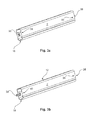
- FIGS. 3 a and 3 b show a linear curtain rail component in two different directions;
- FIG. 3 c shows a curved curtain rail component and
- FIG. 3 d shows an aircraft cabin curtain rail assembled using linear and curved curtain rail components.
- FIGS. 4 a to 4 d show a positive locking means for arresting a fixation protrusion and a recess.
- FIGS. 5 a and 5 b show another positive locking means for arresting a fixation protrusion and a recess.
- FIGS. 6 a to 6 f show another positive locking means for arresting a fixation protrusion and a recess.
- FIG. 7 shows an aircraft with a cabin and a curtain supported on an aircraft cabin curtain rail assembled by use of an aircraft cabin curtain rail assembly kit.
- FIG. 1 shows an overview of a possible aircraft cabin curtain rail assembly kit.
- Exemplarily two linear or longitudinal curtain rail components 2 and 4 are named part “A” and part “B”.
- Part A exemplarily has a length of 50 cm;
- part B exemplarily has a length of 60 cm.
- These dimensions allow creating an aircraft cabin curtain rail with a most common lateral extension for providing a cabin zone separation for the most common commercial aircraft.
- the respective passageways over which the aircraft cabin curtain rail to be created spans usually comprise a certain lateral extension for allowing a person to walk through. Often, besides lateral extension also longitudinal extensions are necessary as cabin components that define these passageways may be shifted relative to each other in a longitudinal direction.
- a curved curtain rail component 6 is provided as a part “C” that has a radius of curvature of 10 cm and a curvature angle of 90°.
- a further exemplary linear curtain rail component 8 is provided and has a length of 10 cm.
- a still further curtain rail component 10 is curved and has a curvature angle of about 10°.
- the core aspect is to provide a plurality of different combinable curtain rail components that may form every necessary aircraft cabin curtain rail.
- one or more of the depicted variety of curtain rail components 2 to 10 create an aircraft cabin curtain rail that is tailored to an individual passageway in an aircraft cabin that is to be separated by means of a curtain.
- the curtain rail components 2 to 10 comprise a holder slit 12 or 14 and a curtain slit 16 or 18 .
- the curtain rail cross-section in FIG. 2 a comprises an upper part 20 which is flat at its top and comprises the holder slit 12 .
- Supporting brackets or slidable and clamping supporting bodies can be inserted into a hollow space 22 of the upper part 20 that allow the extension of fastening means from the hollow space 22 through the holder slit 12 into a panel, a body, a monument, or any other means to which the aircraft cabin curtain rail shall be mounted.
- With a flat top the upper part 20 of the aircraft cabin curtain rail of FIG. 2 a may be easily pressed onto a planar surface so as to provide an additional directional stability of the aircraft cabin curtain rail.
- FIG. 2 b there is demonstrated an upper part 24 of a curtain rail cross-section, wherein the upper part comprises a hollow space 26 that may be used similarly as the hollow space 22 of FIG. 2 a .
- the upper part 24 is completely rounded.
- both cross-sections shown in FIG. 2 a and FIG. 2 b have a lower part 26 and 28 that are rounded and comprise the curtain slit 16 and 18 respectively.
- the curtain rail cross-section in FIG. 2 a is symmetrical about a vertical axis 30 and the curtain rail cross-section in FIG. 2 b is symmetrical about the vertical axis 30 and the horizontal axis 32 .
- FIG. 3 a shows the linear curtain rail component 2 , i.e. part A, in a three-dimensional view.
- a first end 34 has a recess 36 that is dimensioned to receive a fixation protrusion 38 of a second end 40 .
- the curtain rail component 2 has a holder slit 12 by means of which the curtain rail component 2 may be mounted on another component.
- the curtain rail component 2 comprises a curtain slit 16 that allows inserting slidable curtain holders that are not depicted herein.
- each curtain rail component of the aircraft cabin curtain rail assembly kit has a first end 34 with a recess 36 and a second end 40 with a fixation protrusion 38 . Therefore, it is not the intention to insert the fixation protrusion 38 into the recess 36 of the same curtain rail component. Instead, each fixation protrusion 38 of a second end 40 of any curtain rail component may be inserted into the recess 36 of any other curtain rail component. Thereby, a chain of different curtain rail components create an individually tailored aircraft cabin curtain rail.
- the holder slit 12 and the curtain slit 16 of two adjacent curtain rail components are exactly aligned relative to each other for allowing an unobstructed motion of the curtain or of any holders or brackets that are inserted into the hollow spaces of the curtain rail components. It therefore is feasible to use a non-circular cross section and preferably a rectangular cross-section for the fixation protrusion that provides an exact alignment.
- FIG. 3 b shows the curtain rail component 2 back to front for an improved visibility of the fixation protrusion 38 , which fixation protrusion 38 may be realized as an elongated extension having a non-circular, preferably rectangular cross section, for providing an optimal alignment function.
- FIG. 3 c shows the curved curtain rail component 6 , i.e. part C, which curtain rail component 6 also has a first end 34 with a recess 36 and a second end 40 with a fixation protrusion 38 .
- FIG. 3 d shows a number of different curtain rail components attached to each other to create an aircraft cabin curtain rail with an individually tailored geometrical shape.
- a linear curtain rail component part A is used, afterwards a curved curtain rail component part E, afterwards two curtain rail components D, a curtain rail component part A, a curtain rail component part E and another curtain rail component part E.
- this specific geometrical shape would have been created individually by bending or molding the aircraft cabin curtain rail.
- FIGS. 4 a to 4 d A first exemplary embodiment is shown in FIGS. 4 a to 4 d.
- FIG. 4 a shows a fixation protrusion 42 that has a non-circular cross-section and comprises a locking body 44 that extends from a surface 46 of the fixation protrusion 42 perpendicularly to a local longitudinal axis 48 of the curtain rail component.
- This locking body enables a snap-in connection in a respective recess.
- FIG. 4 b shows a possible geometrical shape of the locking body 44 that may be rounded at an end 50 that faces away from the surface 46 in a magnified view.
- the locking body 50 is inserted into a receiving hole 52 , in which receiving hole 52 a spring 54 may be inserted that constantly exerts an outwardly directed pushing force onto the locking body 50 .
- a spring 54 may be inserted that constantly exerts an outwardly directed pushing force onto the locking body 50 .
- FIG. 4 c shows a recess 56 into which the fixation protrusion 46 may be inserted.
- the locking body 44 By pushing the locking body 44 into the receiving hole 52 , e.g. by a finger or a tool, its end 50 ultimately disappears in the recess 56 until it is released by removing the finger or the tool.
- an opening 58 that extends from a lateral walling 62 of the recess 56 facing a slit 60 and extending into the recess 56 , as visible from the magnified view in FIG. 4 d , the locking body 44 snaps into the opening 58 .
- the opening 58 is oriented perpendicularly to the local longitudinal axis 64 of the first end 34 of the curtain rail component shown in FIG. 4 c and engages the locking body 44 in a positive fit connection.
- the slit 60 may either be a curtain slit or a support slit.
- a fixation protrusion 64 may be equipped with a through-hole 66 that extends through the whole fixation protrusion 64 perpendicularly to its local longitudinal axis 48 .
- the through-hole 66 corresponds to an opening 70 that extends through the lateral walling 62 into the recess 68 such that, when the fixation protrusion 64 is inserted into the recess 68 , a screw may be inserted into the opening 70 and may be screwed into a thread at the opposite end of the recess 68 .
- the fixation protrusion 64 may have a thread in the through-hole 66 for screwing a screw directly into the thread of the through-hole 66 .
- the fixation may furthermore be simplified.
- FIGS. 6 a to 6 f show a further exemplary embodiment in simplified three-dimensional views. For the sake of clarity wallings of a recess of a first end of a curtain rail component is simplified. The fixation protrusion is not depicted.
- FIG. 6 a depicts a locking means 72 that comprises an elongated body 74 with a circular cross-section and a pin 76 that extends through the elongated body 74 perpendicularly to a longitudinal axis of the elongated body 74 .
- a radial projection 78 in the shape of a disc is present, which radial projection comprises a slit 80 for insertion of a screw-driver or a coin.
- FIG. 6 b demonstrates a part of a first end of a curtain rail component with a walling 80 of a recess that comprises a through-hole 82 with a shape that corresponds to the cross-section of the elongated body 74 with the pin 76 extending therefrom.
- This allows the insertion of the locking means 72 through the walling 80 in an insertion orientation or position.
- At a side facing away from the recess receiving slits 84 are located that allow receiving the pin 76 when turning the locking means 72 appropriately.
- a fixation protrusion comprises a through-hole that corresponds with the through-hole 82 of the walling 80 of the recess
- a combination of a first curtain rail component and a second curtain rail component with a fixation protrusion of the first curtain rail component inserted into the recess of the second curtain rail component may easily be locked relative to each other by inserting the locking means 72 and turning it into an appropriate locking orientation or position.
- the fixation protrusion thereby is held between the radial projection 78 and the walling 80 of the recess.
- a spring may be put onto the elongated body 74 between the pin 76 and the radial projection 78 for exerting a constant force for pressing the pin 76 into the receiving slits 84 .
- FIG. 6 c shows the locking means 72 directly after insertion in an insertion orientation or direction, where the pin 76 extends over the lateral walling 80 before the rotation is initiated.
- FIG. 6 d demonstrates the initiation of the rotation.
- the rotation may be accomplished by a screwdriver or another tool that is engageable with the slit 80 .
- FIG. 6 e the rotation of the locking means 72 is completed and the pin 76 is situated over the receiving slits 84 .
- the rotation may be accomplished about 90° for example.
- FIG. 7 shows an aircraft 88 with a cabin having a passageway defined through two cabin components 92 and 94 , between which an aircraft cabin curtain rail 90 is mounted for holding a separation curtain.
- an aircraft cabin curtain rail 90 may not only extend in a lateral direction, i.e. along a y-axis of an aircraft-fixed coordinate system, but also in a longitudinal direction, i.e. along an x-axis of an aircraft-fixed coordinate system.
Landscapes
- Engineering & Computer Science (AREA)
- Aviation & Aerospace Engineering (AREA)
- Curtains And Furnishings For Windows Or Doors (AREA)
Priority Applications (1)
| Application Number | Priority Date | Filing Date | Title |
|---|---|---|---|
| US13/904,210 US8756760B2 (en) | 2012-05-31 | 2013-05-29 | Aircraft cabin curtain rail assembly kit, aircraft cabin curtain rail and aircraft with an aircraft cabin having a curtain supported on such an aircraft cabin curtain rail |
Applications Claiming Priority (5)
| Application Number | Priority Date | Filing Date | Title |
|---|---|---|---|
| US201261653568P | 2012-05-31 | 2012-05-31 | |
| EP12170335.9 | 2012-05-31 | ||
| EP12170335.9A EP2669196B1 (de) | 2012-05-31 | 2012-05-31 | Schienenanordnungskit für Flugzeugkabinenvorhang, Schiene für Flugzeugkabinenvorhang und Flugzeug mit Flugzeugkabine mit Vorhang, der auf dieser Kabinenvorhangschiene angebracht ist |
| EP12170335 | 2012-05-31 | ||
| US13/904,210 US8756760B2 (en) | 2012-05-31 | 2013-05-29 | Aircraft cabin curtain rail assembly kit, aircraft cabin curtain rail and aircraft with an aircraft cabin having a curtain supported on such an aircraft cabin curtain rail |
Publications (2)
| Publication Number | Publication Date |
|---|---|
| US20130318744A1 US20130318744A1 (en) | 2013-12-05 |
| US8756760B2 true US8756760B2 (en) | 2014-06-24 |
Family
ID=46201439
Family Applications (1)
| Application Number | Title | Priority Date | Filing Date |
|---|---|---|---|
| US13/904,210 Active US8756760B2 (en) | 2012-05-31 | 2013-05-29 | Aircraft cabin curtain rail assembly kit, aircraft cabin curtain rail and aircraft with an aircraft cabin having a curtain supported on such an aircraft cabin curtain rail |
Country Status (3)
| Country | Link |
|---|---|
| US (1) | US8756760B2 (de) |
| EP (1) | EP2669196B1 (de) |
| CN (1) | CN103507957B (de) |
Cited By (5)
| Publication number | Priority date | Publication date | Assignee | Title |
|---|---|---|---|---|
| US10517418B2 (en) * | 2017-09-08 | 2019-12-31 | Hangzhou Binthen Intellingent Technology Co., Ltd. | Assembling curtain rail |
| US10543919B2 (en) | 2015-06-25 | 2020-01-28 | Bombardier Inc. | Aircraft cabin and partition assembly therefor |
| US11034429B2 (en) * | 2018-08-24 | 2021-06-15 | The Boeing Company | Ceiling header system for aircraft cabin |
| KR20210079996A (ko) * | 2019-12-20 | 2021-06-30 | 신광선 | 커튼 레일 커넥터 |
| US11547233B2 (en) * | 2020-02-07 | 2023-01-10 | The Boeing Company | Quick loading curtain track for an aircraft cabin |
Families Citing this family (2)
| Publication number | Priority date | Publication date | Assignee | Title |
|---|---|---|---|---|
| FR3049448B1 (fr) * | 2016-03-30 | 2018-11-30 | Philippe Durand | Tringle de longueur modulable pour rideaux. |
| EP3290340B1 (de) * | 2016-08-30 | 2020-04-15 | Airbus Operations GmbH | Seitliche, linear bewegbare vorhangschiene |
Citations (12)
| Publication number | Priority date | Publication date | Assignee | Title |
|---|---|---|---|---|
| US3043408A (en) * | 1959-03-23 | 1962-07-10 | Warren R Attwood | Metallic framing element |
| FR1388570A (fr) | 1964-04-17 | 1965-02-05 | Julius Schmidt | Dispositif de rideau, notamment pour séparations de cabines |
| US3296651A (en) * | 1964-12-16 | 1967-01-10 | Baker Drapery Studio | Drapery support |
| US4068345A (en) | 1975-10-16 | 1978-01-17 | Riloga-Werk Julius Schmidt | Shower curtain rod assembly |
| US4524698A (en) * | 1982-06-15 | 1985-06-25 | Etablissements Tourtellier S.A. | Modular rail member for the translation of load-bearing carriages on an overhead track |
| US4747182A (en) * | 1986-12-16 | 1988-05-31 | Graber Industries, Inc. | Drapery traverse rod and support bracket |
| US4769862A (en) * | 1986-05-06 | 1988-09-13 | Saturday Knight Ltd. | Shower curtain support |
| US6807791B2 (en) * | 2001-05-17 | 2004-10-26 | Hilti Aktiengesellschaft | Double-rail profile |
| WO2009115378A2 (de) | 2008-03-19 | 2009-09-24 | Airbus Operations Gmbh | Universelle anordnung zum aufnehmen einer vorhangschiene für einen trennvorhang |
| US20090242150A1 (en) | 2008-03-31 | 2009-10-01 | Airbus Deutschland Gmbh | Curtain support assembly, in a framework design, in a cabin of a vehicle |
| US20110191983A1 (en) | 2010-02-10 | 2011-08-11 | My Home Global Company | Curtain rail structure |
| DE202011000055U1 (de) | 2010-11-08 | 2012-02-28 | Nodeko Gmbh | Gardinenschiene und Mittel zur Verbindung zweier Teilstücke derselben |
Family Cites Families (4)
| Publication number | Priority date | Publication date | Assignee | Title |
|---|---|---|---|---|
| DE2432883A1 (de) * | 1974-07-09 | 1976-01-29 | Rigola Werk Schmidt Julius | Innenlaeufer-vorhangschiene |
| CN2766705Y (zh) * | 2004-12-23 | 2006-03-29 | 张云铭 | 一种木质窗帘轨 |
| KR200449596Y1 (ko) * | 2007-11-26 | 2010-07-22 | 조정달 | 천장 설치용 조립형 커튼 레일 |
| CN202173225U (zh) * | 2011-07-15 | 2012-03-28 | 宁波杜亚机电技术有限公司 | 一种窗帘用导轨 |
-
2012
- 2012-05-31 EP EP12170335.9A patent/EP2669196B1/de active Active
-
2013
- 2013-05-29 US US13/904,210 patent/US8756760B2/en active Active
- 2013-05-31 CN CN201310213965.4A patent/CN103507957B/zh active Active
Patent Citations (13)
| Publication number | Priority date | Publication date | Assignee | Title |
|---|---|---|---|---|
| US3043408A (en) * | 1959-03-23 | 1962-07-10 | Warren R Attwood | Metallic framing element |
| FR1388570A (fr) | 1964-04-17 | 1965-02-05 | Julius Schmidt | Dispositif de rideau, notamment pour séparations de cabines |
| US3296651A (en) * | 1964-12-16 | 1967-01-10 | Baker Drapery Studio | Drapery support |
| US4068345A (en) | 1975-10-16 | 1978-01-17 | Riloga-Werk Julius Schmidt | Shower curtain rod assembly |
| US4524698A (en) * | 1982-06-15 | 1985-06-25 | Etablissements Tourtellier S.A. | Modular rail member for the translation of load-bearing carriages on an overhead track |
| US4769862A (en) * | 1986-05-06 | 1988-09-13 | Saturday Knight Ltd. | Shower curtain support |
| US4747182A (en) * | 1986-12-16 | 1988-05-31 | Graber Industries, Inc. | Drapery traverse rod and support bracket |
| US6807791B2 (en) * | 2001-05-17 | 2004-10-26 | Hilti Aktiengesellschaft | Double-rail profile |
| WO2009115378A2 (de) | 2008-03-19 | 2009-09-24 | Airbus Operations Gmbh | Universelle anordnung zum aufnehmen einer vorhangschiene für einen trennvorhang |
| US20110042434A1 (en) | 2008-03-19 | 2011-02-24 | Airbus Operations Gmbh | Universal arrangement for receiving a curtain rail for a partitioning curtain |
| US20090242150A1 (en) | 2008-03-31 | 2009-10-01 | Airbus Deutschland Gmbh | Curtain support assembly, in a framework design, in a cabin of a vehicle |
| US20110191983A1 (en) | 2010-02-10 | 2011-08-11 | My Home Global Company | Curtain rail structure |
| DE202011000055U1 (de) | 2010-11-08 | 2012-02-28 | Nodeko Gmbh | Gardinenschiene und Mittel zur Verbindung zweier Teilstücke derselben |
Cited By (5)
| Publication number | Priority date | Publication date | Assignee | Title |
|---|---|---|---|---|
| US10543919B2 (en) | 2015-06-25 | 2020-01-28 | Bombardier Inc. | Aircraft cabin and partition assembly therefor |
| US10517418B2 (en) * | 2017-09-08 | 2019-12-31 | Hangzhou Binthen Intellingent Technology Co., Ltd. | Assembling curtain rail |
| US11034429B2 (en) * | 2018-08-24 | 2021-06-15 | The Boeing Company | Ceiling header system for aircraft cabin |
| KR20210079996A (ko) * | 2019-12-20 | 2021-06-30 | 신광선 | 커튼 레일 커넥터 |
| US11547233B2 (en) * | 2020-02-07 | 2023-01-10 | The Boeing Company | Quick loading curtain track for an aircraft cabin |
Also Published As
| Publication number | Publication date |
|---|---|
| EP2669196A1 (de) | 2013-12-04 |
| CN103507957B (zh) | 2016-07-13 |
| EP2669196B1 (de) | 2019-07-03 |
| CN103507957A (zh) | 2014-01-15 |
| US20130318744A1 (en) | 2013-12-05 |
Similar Documents
| Publication | Publication Date | Title |
|---|---|---|
| US8756760B2 (en) | Aircraft cabin curtain rail assembly kit, aircraft cabin curtain rail and aircraft with an aircraft cabin having a curtain supported on such an aircraft cabin curtain rail | |
| US6712543B1 (en) | Connecting device for profiled bars with grooves | |
| US8833018B2 (en) | Mounting system and method for mounting a dividing wall on a holding device, and device for dividing regions | |
| CN103108681A (zh) | 模块化结构系统、用在该结构系统中的结构元件、耦合元件、端部元件和工具 | |
| KR101436965B1 (ko) | 실험 테이블의 조립 시스템 | |
| CA2841533C (en) | Add-on wall panel arrangement for wall systems | |
| WO2014171978A1 (en) | Hanger system for suspendible illuminated fixtures | |
| US7752813B2 (en) | Partitioning system | |
| AU2008324400A1 (en) | Connecting fitting and installation arrangement | |
| EP3009045A1 (de) | Zarge für eine schublade mit einem zargenkörper sowie schublade und möbel mit einer schublade | |
| US20170318987A1 (en) | Adapter, goods carrier and fastening system | |
| EP3048934B1 (de) | Blumenkasten mit anpassbaren haltern zum anbringen und stützen an geländern, mauern oder anderen trägern | |
| CA2748072A1 (en) | System and method for installing columns | |
| US20230340981A1 (en) | Furniture element and piece of furniture | |
| GB2568260A (en) | Wall panel and associated apparatus | |
| DE19646541C1 (de) | Bausatz miteinander verbindbarer Profilelemente | |
| US20140305335A1 (en) | Assembly device and method for the fastening of elements | |
| CN206169932U (zh) | 一种高度可调的支承工装 | |
| EP3138975A1 (de) | Teleskopische stütze, die zwischen zwei parallelen ebenen eingepasst werden kann, und kit zum stellen von wänden | |
| JP4425686B2 (ja) | 組み立て式台 | |
| CN217684627U (zh) | 一种便于维护的吸顶灯 | |
| CN212339577U (zh) | 空调器 | |
| CN108385864A (zh) | 一种可移动排插组合墙板 | |
| CN202822009U (zh) | 按摩椅扶手上的手控器安装装置 | |
| CN204757292U (zh) | 轴承座固定结构及空调室内机 |
Legal Events
| Date | Code | Title | Description |
|---|---|---|---|
| AS | Assignment |
Owner name: AIRBUS OPERATIONS GMBH, GERMANY Free format text: ASSIGNMENT OF ASSIGNORS INTEREST;ASSIGNORS:ULBRICH-GASPAREVIC, JOVAN;MOSLER, MICHAEL;WARNER, HOLGER;SIGNING DATES FROM 20130530 TO 20130624;REEL/FRAME:030686/0584 |
|
| FEPP | Fee payment procedure |
Free format text: PAYOR NUMBER ASSIGNED (ORIGINAL EVENT CODE: ASPN); ENTITY STATUS OF PATENT OWNER: LARGE ENTITY |
|
| STCF | Information on status: patent grant |
Free format text: PATENTED CASE |
|
| MAFP | Maintenance fee payment |
Free format text: PAYMENT OF MAINTENANCE FEE, 4TH YEAR, LARGE ENTITY (ORIGINAL EVENT CODE: M1551) Year of fee payment: 4 |
|
| MAFP | Maintenance fee payment |
Free format text: PAYMENT OF MAINTENANCE FEE, 8TH YEAR, LARGE ENTITY (ORIGINAL EVENT CODE: M1552); ENTITY STATUS OF PATENT OWNER: LARGE ENTITY Year of fee payment: 8 |