US856495A - Harness attachment. - Google Patents
Harness attachment. Download PDFInfo
- Publication number
- US856495A US856495A US31330406A US1906313304A US856495A US 856495 A US856495 A US 856495A US 31330406 A US31330406 A US 31330406A US 1906313304 A US1906313304 A US 1906313304A US 856495 A US856495 A US 856495A
- Authority
- US
- United States
- Prior art keywords
- strap
- arms
- pin
- slot
- stay
- Prior art date
- Legal status (The legal status is an assumption and is not a legal conclusion. Google has not performed a legal analysis and makes no representation as to the accuracy of the status listed.)
- Expired - Lifetime
Links
Images
Classifications
-
- B—PERFORMING OPERATIONS; TRANSPORTING
- B64—AIRCRAFT; AVIATION; COSMONAUTICS
- B64D—EQUIPMENT FOR FITTING IN OR TO AIRCRAFT; FLIGHT SUITS; PARACHUTES; ARRANGEMENTS OR MOUNTING OF POWER PLANTS OR PROPULSION TRANSMISSIONS IN AIRCRAFT
- B64D17/00—Parachutes
- B64D17/22—Load suspension
- B64D17/30—Harnesses
- B64D17/32—Construction of quick-release box
-
- B—PERFORMING OPERATIONS; TRANSPORTING
- B68—SADDLERY; UPHOLSTERY
- B68B—HARNESS; DEVICES USED IN CONNECTION THEREWITH; WHIPS OR THE LIKE
- B68B5/00—Details or accessories; Fastening devices for bridles, reins, harnesses, or the like
-
- Y—GENERAL TAGGING OF NEW TECHNOLOGICAL DEVELOPMENTS; GENERAL TAGGING OF CROSS-SECTIONAL TECHNOLOGIES SPANNING OVER SEVERAL SECTIONS OF THE IPC; TECHNICAL SUBJECTS COVERED BY FORMER USPC CROSS-REFERENCE ART COLLECTIONS [XRACs] AND DIGESTS
- Y10—TECHNICAL SUBJECTS COVERED BY FORMER USPC
- Y10T—TECHNICAL SUBJECTS COVERED BY FORMER US CLASSIFICATION
- Y10T24/00—Buckles, buttons, clasps, etc.
- Y10T24/47—Strap-end-attaching devices
- Y10T24/4764—Ring-loop
Definitions
- This invention relates to devices for repairing head-stalls, halters and other portions of harness and more particularly to improved means for fastening the stay-strap of a headstall to the throat and chin straps.
- the object of the invention is to provide a comparatively simple, inexpensive and efficient device of this character by means of which discarded portions of harness-straps or scraps of leather may be utilized for connecting the throat and chin straps of a headstall in case the continuous strap usually em ployed for this purpose becomes worn, sevcred or otherwise unfit for service.
- a still further object of the invention is to generally improve this class of devices so as to increase their utility, durability and efli,
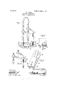
- Figure 1 is a perspective view of a head-stall or halter showing the application of the device.
- Fig. 2 is a detail perspective view of the attaching or connecting clip detached.
- Fig. 3 is a side elevation partly in section of a portion of the clip.
- Fig. 4 is a perspective view of a portion of the harness showing the connecting clip in position on the throat latch.
- the improved device is principally designed for connecting broken or severed staystraps of head-stalls or halters and by way of illustration is shown applied to a head-strap of the ordinary construction in which 5 designates the nose-strap, 6 the crown-strap and 7 the vertical stay-strap connecting the chinstrap 8 and throat latch 9 as shown.
- connecting clip is preferably formed of a single strip of metal an intermediate portlon of which is bent or curved upon itself as indicated at 10 to form a pair of clamping arms 11 and 12 adapted to receive the broken or severed portions of the stay-strap 7, said arms being provided with spaced apertures or perforations 13 for the reception of suit able rivets or other fastening devices 14
- the longitudinal edges of the clamping arms 11 and 12 are formed with inwardly extending flanges 15 between which is seated a packing 16 preferably in the form of a strip of leather as shown and designed to prevent undue wear on the adjacent ends of the staystrap.
- the ring 18 is retained within the slot 17 by means of a pin or rod 18, said pin being locked in position by bending the laterally extending lugs 19 in engagement with the adjacent end. of the pin as shown.
- the broken or severed portions of the stay-strap are introduced between the clamping arms 11 and 12 and secured thereto by the rivets or fastening devices 14 after which the ring is introduced in the slot 17 and the cars 19 bent laterally into engagement with the adjacent end of the pin 18 thereby securing the stay-strap in position and permitting the latter to slide free over the chin-strap in the ordinary manner.
- the device is used for connecting the stay-strap and throatlatch the cars 19 are bent inwardly within the curved portion 10 and the throat-strap threaded through the loop formed by the closed end of the arms as clearly shown in Fig. 4 of the drawings.
- a device of the class described comprising a body-portion having an intermediate portion thereof provided with a longitudinal slot and bent to form a pair of clamping arms adapted to engage a strap, a ring seated in said slot, a pin passing through the ring and bearing against the arms at the juncture of the latter, and means carried by the arms and engaging the opposite ends of the pin for preventing accidental displacement of said pin.
- a device of the class described comprising a body-portion having an intermediate portion thereof provided with a longitudinal slot and bent to form a pair of clamping arms adapted to engage a strap, a ring seated in the slot, a pin piercing the ring and lugs eX' tending laterally from the clamping arms on each side of the slot and adapted to engage the opposite ends of the pin.
- a device of the class described comprising a body-portion having an intermediate portion thereof bent to form a pair of clamping arms adapted to engage a strap, said arms being provided with a longitudinal slot disposed at the juncture of the arms, a pin interposed between I the arms and bearing against the interior Walls thereof at said slot,
- a device of the class described comprising a pair of-clamping arms adapted to engage a strap and having their united ends formed with a longitudinalslot, flanges extending inwardly from the opposite longitudinal edges of said arms, a yieldable packing interposed between the arms and locked. in position by engagement with the flanges, there being an'opening formed in the packing at said slot, a ring seated in the slot and bearing against the packing, a pin interposed be tween the arms and passing through the ring, and lugs projecting from the arms on each side of the slot and bent laterally into engagement with the opposite ends of the pin.
Description
No. 856,495. PATENTED JUNE 11, 1907.
N. 0. SIKES. HARNESS ATTACHMENT.
APPLICATION FILED APR-23, 1908.
Nmafon 6T 527%5;
WITNESSES.-
A TTORNE 1/5 UNITED STATES PATENT OFFICE.
HARNESS ATTACHMENT.
Specification of Letters Patent.
Patented June 11, 1907.
Application filed A il 23,1906. Serial No. 313,304.
T0 aZZ whom it may concern.-
Be it known that I, NEWTON C. SIKES, a citizen of the United States, residing at Dallas City, in the county of Hancock and State of Illinois, have invented a new and useful Harness Attachment, of which the following is a specification.
This invention relates to devices for repairing head-stalls, halters and other portions of harness and more particularly to improved means for fastening the stay-strap of a headstall to the throat and chin straps.
The object of the invention is to provide a comparatively simple, inexpensive and efficient device of this character by means of which discarded portions of harness-straps or scraps of leather may be utilized for connecting the throat and chin straps of a headstall in case the continuous strap usually em ployed for this purpose becomes worn, sevcred or otherwise unfit for service.
A still further object of the invention is to generally improve this class of devices so as to increase their utility, durability and efli,
ciency as well as to reduce the cost of manufacture.
lVith these and other objects in view the invention consists in the construction and novel combination and arrangement of parts hereinafter fully described, and illustrated in the accompanying drawings, it being understood that various changes in form, proportions and minor details of construction may be resorted to within the scope of the appended claims.
In the accompanying drawings forming a part of this specification: Figure 1 is a perspective view of a head-stall or halter showing the application of the device. Fig. 2 is a detail perspective view of the attaching or connecting clip detached. Fig. 3 is a side elevation partly in section of a portion of the clip. Fig. 4 is a perspective view of a portion of the harness showing the connecting clip in position on the throat latch.
Similar numerals of reference indicate corresponding parts in all of the figures of the drawings.
The improved device is principally designed for connecting broken or severed staystraps of head-stalls or halters and by way of illustration is shown applied to a head-strap of the ordinary construction in which 5 designates the nose-strap, 6 the crown-strap and 7 the vertical stay-strap connecting the chinstrap 8 and throat latch 9 as shown. The
connecting clip is preferably formed of a single strip of metal an intermediate portlon of which is bent or curved upon itself as indicated at 10 to form a pair of clamping arms 11 and 12 adapted to receive the broken or severed portions of the stay-strap 7, said arms being provided with spaced apertures or perforations 13 for the reception of suit able rivets or other fastening devices 14 The longitudinal edges of the clamping arms 11 and 12 are formed with inwardly extending flanges 15 between which is seated a packing 16 preferably in the form of a strip of leather as shown and designed to prevent undue wear on the adjacent ends of the staystrap. Extending longitudinally of the body of the clip and opening through the curved end 10 is an elongated slot 17 adapted to receive a ring or loop 18 for connecting the stay-strap to the chin-strap of the halter. The ring 18 is retained within the slot 17 by means of a pin or rod 18, said pin being locked in position by bending the laterally extending lugs 19 in engagement with the adjacent end. of the pin as shown.
In using the device the broken or severed portions of the stay-strap are introduced between the clamping arms 11 and 12 and secured thereto by the rivets or fastening devices 14 after which the ring is introduced in the slot 17 and the cars 19 bent laterally into engagement with the adjacent end of the pin 18 thereby securing the stay-strap in position and permitting the latter to slide free over the chin-strap in the ordinary manner.
Then the device is used for connecting the stay-strap and throatlatch the cars 19 are bent inwardly within the curved portion 10 and the throat-strap threaded through the loop formed by the closed end of the arms as clearly shown in Fig. 4 of the drawings.
While the device is principally designed for connecting broken or severed stay-straps it is obvious that the same may be used for connecting other portions of a harness or wherever a device of this kind is found desirable.
From the foregoing description it will be seen that there is provided an extremely simple, inexpensive and efficient device admirably adapted for the attainment of the ends in view.
Having thus described the invention what is claimed is:
1. A device of the class described comprising a body-portion having an intermediate portion thereof provided with a longitudinal slot and bent to form a pair of clamping arms adapted to engage a strap, a ring seated in said slot, a pin passing through the ring and bearing against the arms at the juncture of the latter, and means carried by the arms and engaging the opposite ends of the pin for preventing accidental displacement of said pin.
2. A device of the class described comprising a body-portion having an intermediate portion thereof provided with a longitudinal slot and bent to form a pair of clamping arms adapted to engage a strap, a ring seated in the slot, a pin piercing the ring and lugs eX' tending laterally from the clamping arms on each side of the slot and adapted to engage the opposite ends of the pin.
3. A device of the class described comprising a body-portion having an intermediate portion thereof bent to form a pair of clamping arms adapted to engage a strap, said arms being provided with a longitudinal slot disposed at the juncture of the arms, a pin interposed between I the arms and bearing against the interior Walls thereof at said slot,
a ring seated in the slot and engaging the pin, and lugs projecting from the arms and bent laterally into engagement with the opposite ends of the pin.
4. A device of the class described comprising a pair of-clamping arms adapted to engage a strap and having their united ends formed with a longitudinalslot, flanges extending inwardly from the opposite longitudinal edges of said arms, a yieldable packing interposed between the arms and locked. in position by engagement with the flanges, there being an'opening formed in the packing at said slot, a ring seated in the slot and bearing against the packing, a pin interposed be tween the arms and passing through the ring, and lugs projecting from the arms on each side of the slot and bent laterally into engagement with the opposite ends of the pin.
In testimony that I claim the foregoing as my own, I have hereto affiXed my signature in the presence of two witnesses.
NEl/VTON O. SIKES.
lVitnesses:
l/VALLAOE DIVER, CHAS. WV. SMITH.
Priority Applications (1)
| Application Number | Priority Date | Filing Date | Title |
|---|---|---|---|
| US31330406A US856495A (en) | 1906-04-23 | 1906-04-23 | Harness attachment. |
Applications Claiming Priority (1)
| Application Number | Priority Date | Filing Date | Title |
|---|---|---|---|
| US31330406A US856495A (en) | 1906-04-23 | 1906-04-23 | Harness attachment. |
Publications (1)
| Publication Number | Publication Date |
|---|---|
| US856495A true US856495A (en) | 1907-06-11 |
Family
ID=2924950
Family Applications (1)
| Application Number | Title | Priority Date | Filing Date |
|---|---|---|---|
| US31330406A Expired - Lifetime US856495A (en) | 1906-04-23 | 1906-04-23 | Harness attachment. |
Country Status (1)
| Country | Link |
|---|---|
| US (1) | US856495A (en) |
-
1906
- 1906-04-23 US US31330406A patent/US856495A/en not_active Expired - Lifetime
Similar Documents
| Publication | Publication Date | Title |
|---|---|---|
| US856495A (en) | Harness attachment. | |
| US420871A (en) | Buckle | |
| US862782A (en) | Harness-loop. | |
| US350081A (en) | Loop or band for straps | |
| US899281A (en) | Overdraw check-loop for bridles. | |
| US1281450A (en) | Harness-buckle. | |
| US513919A (en) | Hame-tug | |
| US1212765A (en) | Harness attachment. | |
| US1085796A (en) | Buckle. | |
| US795879A (en) | Buckle. | |
| US908843A (en) | Breast-strap snap-hook. | |
| US901173A (en) | Clip-hook. | |
| US399788A (en) | Halter bolt-clip | |
| US858250A (en) | Tail-holder. | |
| US787872A (en) | Cast-off. | |
| US792171A (en) | Harness-loop. | |
| US216155A (en) | Improvement in hame-fasteners | |
| US1065171A (en) | Buckle and the like. | |
| US348186A (en) | burg-ess | |
| US359494A (en) | Hame-fastener | |
| US318409A (en) | Thirds to michael andes and henry andes | |
| US182452A (en) | Improvement in buckles | |
| US1068520A (en) | Trace-carrier. | |
| US55942A (en) | Improved harness-hook | |
| US1060045A (en) | Back-band for harness. |